dynamic response of the non-contact underwater … response of the non-contact underwater explosions...
TRANSCRIPT

Marine Structures 24 (2011) 396–411
Contents lists available at ScienceDirect
Marine Structuresjournal homepage: www.elsevier .com/locate/
marstruc
Dynamic response of the non-contact underwaterexplosions on naval equipment
Zhang Aman a,b,*, Zhou Weixing a, Wang Shiping a, Feng Linhan a
aCollege of Shipbuilding Engineering, Harbin Engineering University, Harbin 150001, ChinabDepartment of Mechanical Engineering, University College London, Torrington Place, London WC1E 7JE, UK
a r t i c l e i n f o
Article history:Received 8 November 2010Received in revised form 1 April 2011Accepted 18 May 2011
Keywords:Underwater explosionShipboard equipmentHull structureIntegrationImpact response
* Corresponding author. College of ShipbuildiTel.: þ86 0451 8251 8296.
E-mail address: [email protected] (Z. Am
0951-8339/$ – see front matter � 2011 Elsevier Ltdoi:10.1016/j.marstruc.2011.05.005
a b s t r a c t
Shock resistance capacity of the shipboard equipment especially forlarge ones, has been a strong concern of navies all over theworld fora long time. The shipboard equipment have previously generallybeen studied separate from hull structure before. In this paper thecoupling elastic effect betweenequipment andhull structure is takeninto account.With theABAQUS software, the integratedmodel of theequipment coupledwith thehull structure is established to study thedynamic response of the shipboard equipment to the shock waveload as well as the bubble pulsation load. In order to verify thenumerical method, the simulated results are compared to theexperimental data, which are from a specific underwater explosionon an actual ship. On this basis, by changing the charge location,attack angle, equipment installation location and other parameters,the characteristics of dynamic response under different conditionscan be obtained. In addition, the results of the integrated calculationand the non-integrated one are compared and the characteristicparameterswhich affect theequipment shock response are analyzed.Some curves and conclusions are obtained for engineering applica-tions, which provides some insights into the shock resistance ofshipboard equipment.
� 2011 Elsevier Ltd. All rights reserved.
1. Introduction
As is known, it is inevitable for a warships to encounter impact environment during his service life.The contact explosions cause direct damages to the ship structure as well as the internal equipment,
ng Engineering, Harbin Engineering University, Harbin 150001, China.
an).
d. All rights reserved.

Z. Aman et al. / Marine Structures 24 (2011) 396–411 397
while the non-contact explosions [1–5] will usually not cause the breakdown of the ship structure butwill cause large-scale damages to the naval equipment [6–8]. Therefore, the anti-shock performance ofshipboard equipment plays an important role in service life of a warship. Besides, both the full-scaleship explosion tests and the model ship experiments have shown that the bubble load will causedamages not only to the general ship structure, but also to the large-scale shipboard equipment [9,10].The shockwave load resulting from underwater explosionsmainly causes local damages to ships, whilethe bubble pulsation load with low-frequency characteristic could trigger the general step displace-ment of warships [11]. According to the experimental study on the floating impacted platform, severalresearchers have found that step displacements are the main cause of damages to the shipboardequipment with 10 Hz installation frequency [12].
Resulting from the large volume and mass of the shipboard equipment, it is difficult and expensiveto perform the impact tests for a full-scale ship. Instead the numerical calculation becomes an effectivemethod to the study of the anti-shock performance of the shipboard equipment. In previous evalua-tions, the equipment and the ship hull were studied separately according to the relevant standards,such as Germanic military standard BV0430-85 [13], with the coupling effect between them rarelyconsidered. Some relevant studies have showed that this simplified method could not precisely matchthe full-scale ship shock environment for shipboard equipment. In this paper, the warship super-charging boiler is chosen as the study object, Based on the theory of master-slave system couplingvibration [14], a finite element model of integrated shipboard equipment and hull is created byconsidering the coupled effects between them.
Based on the ABAQUS software, the Geers-Hunter theory [15] to calculate the shock wave andbubble load in the underwater explosions, and the acoustic medium is to simulate the shock wave andbubble propagation in water. Once the load arrives at the ship hull, the interaction between the ship’swet surface and surrounding flow field can be calculated by acoustic-structure coupling method. Thenthe damages to the shipboard equipment resulting from bubble load during underwater explosion canbe analyzed based on the integrated ship-equipment model. Furthermore, in order to study themechanism of the damage to the shipboard equipment caused by underwater explosion load, the effectof different parameters on the equipment response is investigated, including the explosion depth, theattack angle, and the position of the detonation point along the ship’s length. Some curves are thenshown to represent the results obtained.
2. Numerical Calculation Method
Based on the ABAQUS software, the acoustic-structure coupling method is used to calculate thepropagation of the underwater explosion pressure in water and the interaction between the ship’s wetsurface and the surroundingwater. Different boundary conditions in the flow field, such as the free surfaceboundary condition and the non-reflective boundary condition are all considered in the analysis. The basictheory of the acoustic-structure coupling method can be found in references [16,17].
Further assuming that the fluid is compressible [16], adiabatic and its motion is small, themomentum equation for the fluidwith velocity-dependentmomentum losses can be expressed as [16]:
vpvx
þ aðx;KiÞ _vf þ Df ðx;KiÞ€vf ¼ 0 (1)
Where, p is the dynamic pressure in the fluid (the pressure in excess of any static pressure); x is thefluid particle’s spatial position; _vf and €vf is the fluid particle velocity and acceleration separately; Df isfluid density; a is the force per unit volume per velocity; and Ki are dependent field variables such astemperature, humidity, or salinity, etc.
Further assuming the fluid to be inviscid, linear and compressible [16], the constitutive equation ofthe fluid can be expressed as:
pþ Rf ðx;KiÞvvfvx
¼ 0 (2)
Where, vf is the fluid particle displacement, Rf is the bulk modulus of the fluid.

Z. Aman et al. / Marine Structures 24 (2011) 396–411398
In order to obtain the partial differential equation used in direct integration transient analysis,divide equation (1) by Df and derive the result with respect to x. Assuming that the analysis is transientand neglecting the derivative ofa/Df, combine the result with the time derivatives of equation (2), andthen get the differential equation for the fluid in terms of the fluid pressure can be obtained as [16]:
1Rf
€pþ a
Df Rf_p� v
vx,
1Df
vpvx
!¼ 0 (3)
Introducing an arbitrary variation field dp, and integrating equation (3) over thewhole fluid field, anequivalent weak form for the equation of motion can be obtained [16]:
ZVf
dp
"1Rf
€pþ a
Df Rf_pþ v
vx
1Df
vpvx
!#dV ¼ 0 (4)
Through the coupled acoustic-structural medium analysis from ABAQUS [16], we obtain the fluidfield equilibrium equation [16]:
ZSfs
dpn�,€vmdS¼ZVf
dp
" 1Rf
€pþ a
Df Rf_p
!þ 1Df
vdpvx
,vpvx
#dVþ
ZSfi
dp�1d1
_pþ 1a1
p�dSþ
ZSfr
dp
"a
Df
1d1
p
þ
a
Df
1b1
þ 1d1
!_pþ 1
b1€p
#dSþ
ZSft
dpT0dSþZSfrs
dp
a
Df d1pþ
a
Df b1þ 1d1
!_p
þ 1b1
€p�n�,€vm!dS (5)
The structural behavior can be derived by using the virtual work principle [16]:ZV
dvm,tdV ¼ZV
de : sdV þZV
acpdvm, _vmdV þZV
pdvm,€vmdV þZV
pdvm,ndV (6)
Where, dvm is a variational displacement field, t is the drag force of the structure, s is the nodal stressin structure, p is the pressure applied on the structural wet surface, n is the normal of the structuresurface, pointing inside the fluid, D is the density of the structure, ac is the mass proportional dampingfactor, vm, _vm and €vm are the displacement, velocity and acceleration of the structure at one pointseparately, and de is the virtual displacement with respect to the virtual strain.
As above, the structure equilibrium equation in the fluid field can be obtained. Then we discretizethe structure and the acoustic mediumwith Finite Element Method (FEM), and define the surfaces onwhich the pressure is applied. Finally, the pressure load from the underwater explosion by Geers andHunters model (2002) [15] is exerted on the discretized surfaces. As a consequence, the response of the
Fig. 1. The finite element model.

Fig. 2. The fluid field model.
Z. Aman et al. / Marine Structures 24 (2011) 396–411 399
structure together with the pressure propagation in the fluid field can be obtained by solving dis-cretized equation of (5) and (6) with the explicit time integration method.
3. Verification of the numerical simulation method
In order to verify the numerical method, the numerical results are compared to the experimentaldata of the warship underwater explosion. The general water displacement is D, with the ship length L,the width 0.14 L, and the draft 0.04 L, and the interval of the frame is 0.008 L. The finite element modeland the fluid field model are shown in Fig. 1 and Fig. 2 respectively.
The origin of the coordinate system is the intersection point of central longitudinal section, midshipsection and base plane; the X,Y, Z axis points towards the starboard, the bow and upwards respectively.N kg TNTcharge is placed 1.1 L away from the broadside, 0.8 L away from the free surface and 0.3 L awayfrom the midship section near the stern. The time-acceleration history curves of typical position on themain deck are showed in Fig. 3.
It can be seen from Fig. 3 that the result of our model coincides well with the experimental data. Atthe shock and pulsation stages, the time-acceleration history curve of the numerical result is similar tothat of the experimental data. The bubble pulsation begins at 0.57 s which can be observed in Fig. 3. Thepeak strain at typical places of the ship is shown in Table 1, with the error defined as
relative error ¼ jE � RjE
� 100%
Where E denotes the experimental value and R is the numerical value.
Fig. 3. (a) Measured value in experiment (b) Numerical result in simulation.
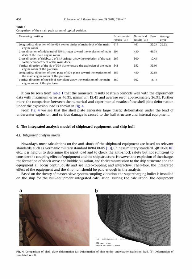
Table 1Comparison of the strain peak values of typical position.
Measuring position Experimentalresults (me)
Numericalresults (me)
Error Averageerror
Longitudinal direction of the 63# center girder of main deck of the mainengine room
617 461 25.2% 26.3%
Cross direction of sideboard of 55# stringer toward the explosion of maindeck of the main engine room
294 430 46.3%
Cross direction of sideboard of 84# stringer away the explosion of the rearsoldier compartment of the main deck
267 300 12.4%
Vertical direction of the rib of 59# plane toward the explosion of the mainengine room of the platform
541 352 35.0%
Longitudinal direction of shell plate of 57# plane toward the explosion ofthe main engine room of the platform
367 450 22.6%
Vertical direction of the rib of 55# plane away the explosion of the mainengine room of the platform
360 302 16.1%
Z. Aman et al. / Marine Structures 24 (2011) 396–411400
It can be seen from Table 1 that the numerical results of strain coincide well with the experimentdata with maximum error as 46.3%, minimum 12.4% and average error approximately 26.3%. Furthermore, the comparison between the numerical and experimental results of the shell plate deformationunder the explosion load is shown in Fig. 4.
From Fig. 4 we see that the shell plate generates large plastic deformation under the load ofunderwater explosion, and serious damage is caused to the hull structure and internal equipment.
4. The integrated analysis model of shipboard equipment and ship hull
4.1. Integrated analysis model
Nowadays, most calculations on the anti-shock of the shipboard equipment are based on relevantstandards, such as Germanicmilitary standard BV0430-85 [13], Chinesemilitary standard GJB1060 [18]etc., it is helpful to determine the input load and to check the anti-shock safety but not sufficient toconsider the coupling effect of equipment and the ship structure. However, the explosion of the charge,the formation of shock wave and bubble pulsation, and their transmission to the ship structure and theequipment all occur continuously and are inter-coupling and interactive. Therefore, the integratedeffect of the equipment and the ship hull should be paid enough in the analysis.
Based on the theory of master-slave system coupling vibration, the supercharging boiler is installedon the ship for the hull-equipment integrated calculation. During the calculation, the equipment
Fig. 4. Comparison of shell plate deformation (a) Deformation of ship under underwater explosion load. (b) Deformation ofsimulated result.

Fig. 5. The finite element model of the equipment and the ship hull.
Z. Aman et al. / Marine Structures 24 (2011) 396–411 401
installation frequency and damping are considered, and the spring-damping element is adopted tosimulate the shock absorber fixed between the boiler and the ship hull. The final installation frequencyof the supercharging boiler is about 10 Hz. The finite element model of the equipment and the ship hullis shown in Fig. 5, where the red stands for equipment and the local model of the supercharging boilerlocated on the ship’s equipment base is shown in Fig. 6.
The position of the charge is shown in Fig. 7. The length, width and draft of XXX ship are denoted asL, B and T. A charge of N kg TNT is located at the position of 0.22 L below the naval equipment’sinstallation position. Generally, the underwater explosion load consists of two stages, the shock wavestage and the bubble pulsation stage. During the shock wave stage, the head of the shock wave is thestep form. Its amplitude value peaks sharply before decays exponentially in a short time after the phasestep. After the shock wave, the gas product of the explosion (the bubble) expands and contracts incycles, whilst the low-frequency pressure is radiated outwards. The underwater explosion shockwaveand bubble pulsation load in this paper are obtained by Geers and Hunters model.
4.2. Response of Warships Subjected to Underwater Explosions
Subjecting to the explosion load, the integrated model of the hull and the equipment is analyzednumerically. The shock wave and bubbles loads act on the integrated model and generate dynamicresponse. The response of the supercharging boiler depends largely on that of the equipment base onthe hull, so the latter is analyzed first. Fig. 8 displays the velocity-time response curve of the equipmentbase and Fig. 9 shows the corresponding displacement-time curve.
It can be seen from Fig. 8 that the high frequency response appears in the first 0.1s which resultingfrom the impact of the shock wave on the ship hull and the low-frequency part shows after 0.5 sbecause of the secondary pulsation pressure, and there are multiple peaks as well. When the bubble
Fig. 6. The local model of the supercharging boiler located on the ship’s equipment base.

Fig. 7. Charge position and equipment’s install position.
Z. Aman et al. / Marine Structures 24 (2011) 396–411402
collapses at about 0.55 s, the response velocity peaks around 1.3m/s, which is only 20% of the first peakvelocity caused by the shock wave. As shown in Fig. 9, the displacement response of the equipmentbase is caused by the long-time pulsation pressure. The equipment base reaches the max-imumdisplacementof about 0.2 m at 0.3 s during the period of the shock wave. However, the responsevelocity reaches another peak in a shorter time (about 0.2 s) with an obvious step property resultingfrom the secondary pressure wave of the bubble load.
Both the analytical and experimental results show that the shock wave is in high frequency andthe bubble load is in low frequency. Compared with the high frequency of the shock wave, that of thebubble load pulse is much lower, which is close to the overall ship’s vertical natural vibrationfrequency and often tends to lead to the overall vibration of the hull. Under the act of the bubble pulseload, the main character of low-frequency response for warships is that the warship heaves with theexpansion and contraction of explosion bubbles, usually accompanied with the whipping movementof the entire ship [19,20]. The motion of the entire ship at different moments caused by underwaterexplosion load is comprehensively studied and the motion at specified moments can be seen inFig. 10.
The motion of the whole warship at different moments (0.1 s, 0.3 s, 0.5 s, 0.6 s and 0.8 s) is shown inFig. 10. For an easier description, the warship is divided into 20 stations along the longitudinaldirection, and installation position for the supercharging boiler is between the 11th and the 12thstation (indicated by the blue broken line). As is clearly shown in Fig. 10, the ship hull makes a first-order vibration motion in the vertical direction during the heave oscillation.
4.3. Dynamics of Equipment Responses with the Ship hull
Through the simulated analysis for thewhole process of the hull subjecting to underwater explosiveload, the dynamic response of the warship and the supercharging boiler under the combined load ofthe shock wave and the bubble is obtained. As two important factors of the hull and equipment
Fig. 8. Velocity-time response curve of the equipment base.
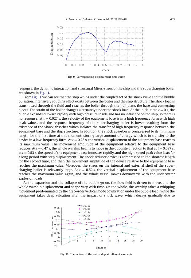
Fig. 9. Corresponding displacement-time curve.
Z. Aman et al. / Marine Structures 24 (2011) 396–411 403
response, the dynamic interaction and structural Mises-stress of the ship and the supercharging boilerare shown in Fig. 11.
From Fig. 11 we can see that the ship whips under the coupled act of the shock wave and the bubblepulsation. Intensively coupling effect exists between the boiler and the ship structure. The shock load istransmitted through the fluid and reaches the boiler through the hull plate, the base and connectingpieces. The strain of the boiler changes alternately under the shock load. At the initial time t ¼ 0 s, thebubble expands outward rapidly with high pressure inside and has no influence on the ship, so there isno response; at t ¼ 0.027 s, the velocity of the equipment base is in a high frequency form with highpeak values, and the response frequency of the supercharging boiler is lower resulting from theexistence of the Shock absorber which isolates the transfer of high frequency response between theequipment base and the ship structure. In addition, the shock absorber is compressed to its minimumlength for the first time at this moment, storing large amount of energy which is to transfer to thedevice in a low-frequency form. At t ¼ 0.28 s, the vertical displacement of the equipment base reachesits maximum value. The movement amplitude of the equipment relative to the equipment basereduces. At t¼ 0.47 s, the whole warship begins to move in the opposite direction to that at t¼ 0.027 s;at t¼ 0.53 s, the speed of the equipment base increases rapidly, and the high-speed peak value lasts fora long period with step displacement. The shock reducer device is compressed to the shortest lengthfor the second time, and then the movement amplitude of the device relative to the equipment basereaches the maximum value. Moreover, the stress on the internal and external shell of the super-charging boiler is relevantly large. At t ¼ 0.62 s, the vertical displacement of the equipment basereaches the maximum value again, and the whole vessel moves downwards with the underwaterexplosion loads.
As the expansion and the collapse of the bubble go on, the flow field is driven to move, and thewhole warship displacement and shape vary with time. On the whole, the warship takes a whippingmovement predominated by the first-order vertical mode of vibration under the bubble load; while theequipment takes deep vibration after the impact of shock wave, which decays gradually due to
Fig. 10. The motion of the entire ship at different moments.

Fig. 11. The dynamic response of the warship and the supercharging boiler under the combination load of the shock wave and thebubble.
Z. Aman et al. / Marine Structures 24 (2011) 396–411404
damping. The base of the supercharging boiler manifests phase-step displacements after the act ofbubble collapse, and the response vibration of the equipment increases again and is more violent thanthat of shock wave impact. To further explain this phenomenon, the response curve of vertical velocityfor typical parts of the equipment is shown in Fig. 12 corresponded with the velocity, and the curve ofthe displacement of the equipment relative to the base of ship is shown in Fig. 13.
It can be seen from Fig. 12that before t ¼ 0.5 s the velocity of the supercharging boiler increasesrapidly resulting from the impact of shock wave and then decays gradually with the same trend as thehull, and the oscillation of the supercharging boiler is based on the natural installation frequency of the

Fig. 12. Response curve of vertical velocity for typical parts.
Z. Aman et al. / Marine Structures 24 (2011) 396–411 405
equipment in this process. After the bubble collapsing, i.e. after t ¼ 0.53 s, the vertical speed of theequipment peaks at 3.3 m/s and exceeds the maximum speed value of 3 m/s induced by shock wave.
As shown in Fig. 13, the vertical displacement of the equipment relative to the ship hull manifests thevibration of the supercharging boiler after being shocked. Because the equipment is connected to thehullbase by the absorber in themodel, the positive and negative values of the vertical displacement in Fig.13represent the tension and compression of the absorber respectively. The absorber of the equipment iscompressed with the rising of the whole hull at initial stage, and the vibration amplitude of the equip-ment is relatively large in the first tensionwith amaximumvalue of 33mm, before themovement beginsto decay. The absorber is compressed during the bubble collapsing; the vibration amplitude value of theequipment in the first tension reaches 44 mm after the bubble collapse, which increases by 33%comparing to that caused by the shock wave. From the analysis above, it can be seen that themovementof the equipment induced by the bubble ismuchmore severe than that induced by shockwave as for theselected model in this calculation.
In order to check the safety of the equipment, the stress response curve of the supercharging boilerat typical positions is shown in Fig. 14. The elements at the internal and external shell of the super-charging boiler have been selected for stress analyses in the process of the calculation. The impact ofshock wave on the external shell of the supercharging boiler produces high stress with a peak value upto 60 MPa. The vibration amplitude and stress reduce resulting from damping. The stress response ofthe equipment increases rapidly and the peak value reaches about 70 MPa after the bubble collapsing,which exceeds that induced by shock wave. However, the stress response at the internal shell of thesupercharging boiler is very low under the load of shock wave, and the peak value of the stressincreases gradually after the bubble collapsing and reaches 61 MPa at 0.72 s, which exceeds the stressresponse caused by shock wave.
The analysis of the equipment stress response shows that the stress caused by underwaterexplosion bubble is more severe than that caused by shock wave. Therefore, it can be concluded thatthe equipment installed with absorber can be severely damaged by bubble load.
Fig. 13. Curve of displacement of equipment relative to ship base.
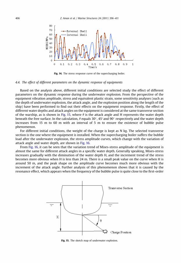
Fig. 14. The stress response curve of the supercharging boiler.
Z. Aman et al. / Marine Structures 24 (2011) 396–411406
4.4. The effect of different parameters on the dynamic response of equipments
Based on the analysis above, different initial conditions are selected study the effect of differentparameters on the dynamic response during the underwater explosion. From the perspective of theequipment vibration amplitude, stress and equivalent plastic strain, some sensitivity analyses (such asthe depth of underwater explosion, the attack angle, and the explosion position along the length of theship) have been performed to find out their effects on the equipment response. Firstly, the effect ofdifferent water depths and attack angles on the equipment is considered at the same transverse sectionof the warship, as is shown in Fig. 15, where q is the attack angle and H represents the water depthbeneath the free surface. In the calculation, q equals 30�, 45�and 90� respectively and the water depthincreases from 15 m to 60 m with an interval of 5 m to ensure the existence of bubble pulsephenomenon.
For different initial conditions, the weight of the charge is kept as N kg. The selected transversesection is the one where the equipment is installed. When the supercharging boiler suffers the bubbleload after the underwater explosion, the stress amplitude curves, which change with the variation ofattack angle and water depth, are shown in Fig. 16.
From Fig. 16, it can be seen that the variation trend of Mises-stress amplitude of the equipment isalmost the same for different attack angles in a specific water depth. Generally speaking, Mises-stressincreases gradually with the diminution of the water depth H, and the increment trend of the stressbecomes more obvious when H is less than 24 m. There is a small peak value on the curve when H isaround 50 m, and the peak shape on the amplitude curve becomes much more obvious with theincrement of the attack angle. Further analysis of this phenomenon shows that it is caused by theresonance effect, which appears when the frequency of the bubble pulse is quite close to the first-order
Fig. 15. The sketch map of underwater explosion.
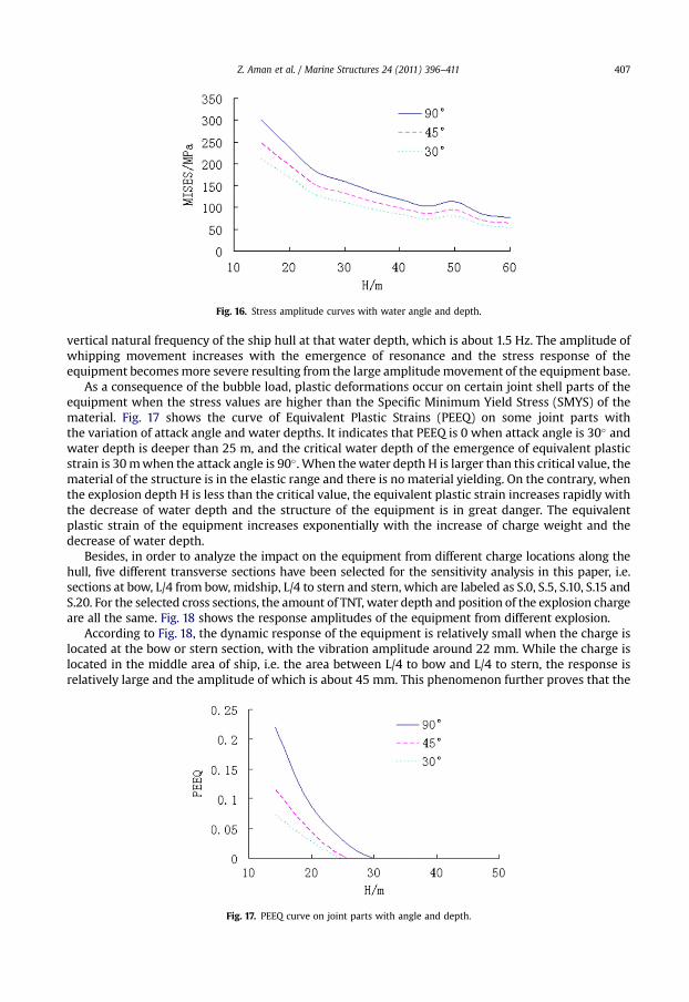
Fig. 16. Stress amplitude curves with water angle and depth.
Z. Aman et al. / Marine Structures 24 (2011) 396–411 407
vertical natural frequency of the ship hull at that water depth, which is about 1.5 Hz. The amplitude ofwhipping movement increases with the emergence of resonance and the stress response of theequipment becomesmore severe resulting from the large amplitudemovement of the equipment base.
As a consequence of the bubble load, plastic deformations occur on certain joint shell parts of theequipment when the stress values are higher than the Specific Minimum Yield Stress (SMYS) of thematerial. Fig. 17 shows the curve of Equivalent Plastic Strains (PEEQ) on some joint parts withthe variation of attack angle and water depths. It indicates that PEEQ is 0 when attack angle is 30� andwater depth is deeper than 25 m, and the critical water depth of the emergence of equivalent plasticstrain is 30mwhen the attack angle is 90�. When thewater depth H is larger than this critical value, thematerial of the structure is in the elastic range and there is no material yielding. On the contrary, whenthe explosion depth H is less than the critical value, the equivalent plastic strain increases rapidly withthe decrease of water depth and the structure of the equipment is in great danger. The equivalentplastic strain of the equipment increases exponentially with the increase of charge weight and thedecrease of water depth.
Besides, in order to analyze the impact on the equipment from different charge locations along thehull, five different transverse sections have been selected for the sensitivity analysis in this paper, i.e.sections at bow, L/4 from bow, midship, L/4 to stern and stern, which are labeled as S.0, S.5, S.10, S.15 andS.20. For the selected cross sections, the amount of TNT, water depth and position of the explosion chargeare all the same. Fig. 18 shows the response amplitudes of the equipment from different explosion.
According to Fig. 18, the dynamic response of the equipment is relatively small when the charge islocated at the bow or stern section, with the vibration amplitude around 22 mm. While the charge islocated in the middle area of ship, i.e. the area between L/4 to bow and L/4 to stern, the response isrelatively large and the amplitude of which is about 45 mm. This phenomenon further proves that the
Fig. 17. PEEQ curve on joint parts with angle and depth.
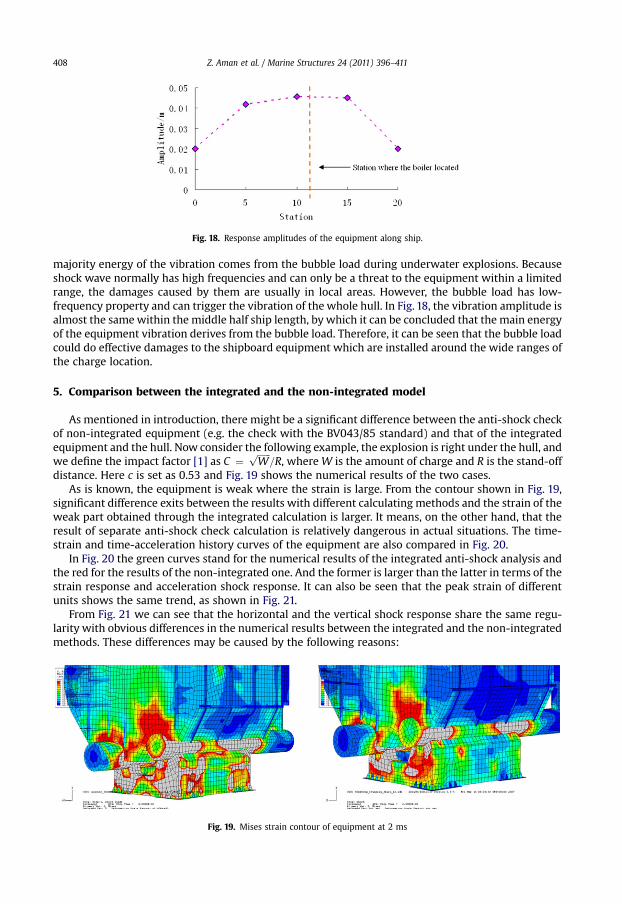
Fig. 18. Response amplitudes of the equipment along ship.
Z. Aman et al. / Marine Structures 24 (2011) 396–411408
majority energy of the vibration comes from the bubble load during underwater explosions. Becauseshock wave normally has high frequencies and can only be a threat to the equipment within a limitedrange, the damages caused by them are usually in local areas. However, the bubble load has low-frequency property and can trigger the vibration of the whole hull. In Fig. 18, the vibration amplitude isalmost the samewithin the middle half ship length, by which it can be concluded that the main energyof the equipment vibration derives from the bubble load. Therefore, it can be seen that the bubble loadcould do effective damages to the shipboard equipment which are installed around the wide ranges ofthe charge location.
5. Comparison between the integrated and the non-integrated model
As mentioned in introduction, there might be a significant difference between the anti-shock checkof non-integrated equipment (e.g. the check with the BV043/85 standard) and that of the integratedequipment and the hull. Now consider the following example, the explosion is right under the hull, andwe define the impact factor [1] as C ¼
ffiffiffiffiffiffiW
p=R, whereW is the amount of charge and R is the stand-off
distance. Here c is set as 0.53 and Fig. 19 shows the numerical results of the two cases.As is known, the equipment is weak where the strain is large. From the contour shown in Fig. 19,
significant difference exits between the results with different calculating methods and the strain of theweak part obtained through the integrated calculation is larger. It means, on the other hand, that theresult of separate anti-shock check calculation is relatively dangerous in actual situations. The time-strain and time-acceleration history curves of the equipment are also compared in Fig. 20.
In Fig. 20 the green curves stand for the numerical results of the integrated anti-shock analysis andthe red for the results of the non-integrated one. And the former is larger than the latter in terms of thestrain response and acceleration shock response. It can also be seen that the peak strain of differentunits shows the same trend, as shown in Fig. 21.
From Fig. 21 we can see that the horizontal and the vertical shock response share the same regu-larity with obvious differences in the numerical results between the integrated and the non-integratedmethods. These differences may be caused by the following reasons:
Fig. 19. Mises strain contour of equipment at 2 ms

Fig. 20. (a) Time-strain curves at typical position. (b) Time-acceleration curves at typical position.
Z. Aman et al. / Marine Structures 24 (2011) 396–411 409
1) There is a strong coupling effect between the hull and the equipment under the shock load, both ofwhich are elastic structures, while the coupling effect is just neglected in the non-integratedanalysis;
2) The shock environments at different spatial locations of the large equipment are different, whilethey are taken as the same in the non-integrated analysis which ignored themulti-point andmulti-direction input characteristics. Therefore, the non-integrated analysis will cause a large error ofmore than 20%.
We analyzed the effect of the impact factor on the results of integrated analysis and non-integratedanalysis, with its value varying from 0.1 to 1.2. Simulated results show that when the impact factorc < 0.45 (i.e. mid and far-field underwater explosions), the value of acceleration and stress response
Fig. 21. (a) Comparisons of responses under horizontal shock. (b) Comparisons of responses under vertical shock.

Z. Aman et al. / Marine Structures 24 (2011) 396–411410
from the non-integrated analysis is relatively larger, which means that we can adopt non-integratedanalysis in the mid and far-field underwater explosions to evaluate the anti-shock features of largeequipment. However, when the impact factor c � 0.45 (i.e. the near-field underwater explosion),smaller responses will generate for the non-integrated anti-shock analysis of equipment compared toactual situations, which means non-integrated analysis is somewhat dangerous for engineeringapplication for near-field explosion.
6. Conclusions
Based on ABAQUS software, the numerical method is verified by comparing the numerical resultswith the experimental data from the warship underwater explosion. The dynamic response can beobtained based on the integrated model of the equipment coupling with the hull structure which iscompared with that of the non-integrated calculation. The suggestions and conclusions are shown asfollows.
1) Shock wave and bubble pulsation of underwater explosionwill induce intensive impact to the hulland shipboard equipment. From the strain and displacement response it can be seen that theamplitude of equipment caused by the bubble pulse is greater. Therefore, bubble load whichinfluences the dynamic response of the equipment can not be ignored.
2) The dynamic response of the equipment changes with water depth and attack angle, if charges arelocated at a particular water depth, where pulsation frequency of the bubble is quite close to thenatural frequency of the ship hull, system resonance and relatively large equipment stressresponses.
3) Based on the sensitivity analyses of the equipment response with different positions of the chargein longitudinal direction, it is found that the bubble load provides most of the energy for thevibration of the equipment. Wherever the explosion is located within the middle half of the wholehull length, the dymamic responses of the equipment are similar. Consequently, the bubble loadcould cause effective damages to the shipboard equipment installed within a wide range of thecharge location.
4) There is a strong elastic coupling effect in integrated calculation of the equipment and the hullstructure and the impact on the equipment is multi-point and non-uniformity inputs, so the non-integrated calculation of equipment and hull structure will make a large error when applied tostudy the shock resistance.
5) When the impact factor c < 0.45 (underwater explosion of the mid and far-field), the accelerationand stress responses obtained by the non-integrated calculation in anti-shock analysis are rela-tively larger than that by integrated calculation. That is to say, we can carry out the evaluation ofthe equipment anti-shock performance with the non-integrated calculation for mid or far-fieldexplosion. However, when the impact factor (the near-field underwater explosion)c� 0.45, smallerresponsewill generate for the non-integrated anti-shock analysis of equipment, whichmeans non-integrated analysis is somewhat dangerous for engineering application for near-field explosion.
Acknowledgments
This work was supported by the National Natural Science Foundation of ChinadNSAF Grant No:10976008 and the State Key Program of National Natural Science of China Grant No:50939002. Authorswould like to acknowledge Professor Wu Guo-xiong of University College London for valuablesuggestions.
References
[1] Cole RH. Underwater explosion. New Jersey: Princeton University Press; 1948. pp. 118–231.[2] Kalumuck KM, Chahine GL, Duraiswami R. Bubble dynamics fluid-structure interaction simulation by coupling fluid BEM
and structural FEM codes. J Fluid Struct 1995;9:861–83.[3] Klaseboer E, Khoo BC, Hung KC. Dynamics of an oscillating bubble near a floating structure. J Fluid Struct 2005;10:1–10.[4] Pozrikidis C. Three-dimensional oscillations of rising bubbles. Eng Anal Bound Elem 2004;28:315–23.

Z. Aman et al. / Marine Structures 24 (2011) 396–411 411
[5] Klaseboer E, Hung KC, Wang C, Wang WC, Khoo BC, Boyce P, et al. Experimental and numerical investigation of thedynamics of an underwater explosion bubble near a resilient/rigid structure. J Fluid Mech 2005;537:387–413.
[6] Keil AH. The response of ships to underwater explosions. Trans Soc Nav Archit Mar Eng 1961;69:366–410.[7] Zamyshlyayev BV. Dynamic load in underwater explosion; 1973. AD-757183.[8] Brooks RP, McNaight BC. Mathematical model of a typical floating shock platform subjected to underwater explosion. The
43rd Shock and Vibration Bulletin, Pt2, 1973.[9] Li GH, Li LJ, Zhang XC. Study of power source for shock environment of ship equipment. The 69th Shock and Vibration
Symposium Minnesota(U-47), 1998. 10.[10] Yao XL, Dai SS, Zhou QX, Zhang AM, Wen XY. Numerical experiment methods for ship hull and equipment integrated
analysis on shock resistance of shipboard equipments. Explo Shock Wave 2009;29(4):367–74.[11] Zong Z. A hydro plastic analysis of a free–free beam floating on water subjected to an underwater bubble. J Fluid Struct
2005;20:359–72.[12] Li GH, Li YJ, Zhang XC, et al. Verification of the relationship between the bubble motion and ship equipment vibration by
test(in Chinese). Ship Mechanics 2005;9(1):98–105.[13] BV0430–85, Germany defense warship construction code-impact security. Koblenz, 1987.[14] Thomson William Tyrrell. Theory of vibration with applications. New Jersey: Prentice-Hall; 1993. pp. 126–147.[15] Geers TL, Hunter KS. An integrated wave-effects model for an underwater explosion bubble. J Acoust Soc Am 2002;111(4):
1584–601.[16] ABAQUS user’s and theory manuals, version 6.8., RI, USA: Dassault Systèmes; 2008.[17] Everstine G. A symmetric potential formulation for fluid-structure interaction. J Sound Vib 1981;79:157–60.[18] GJB 1060,1–1991. General requirement for environmental conditions of naval ships mechanical environments. Beijing;
1991.[19] Hicks AN. The theory of explosion induced ship whipping motions, NCRE Report R579, naval construction Research
Establishment 1972.[20] Vernon TA. Whipping response of ship hulls from underwater explosion bubble load. ADA; 1986.