dynamic separation in air launch: a model - angelo minotti · dynamic separation in air launch: ......
TRANSCRIPT

Technical Session VIII: CUBESAT ACTIVITIES AND CONCEPTS IAA-CU-13-08-04
Dynamic Separation In Air Launch: A Model P. Cafarella*, P.Teofilatto†, A.Minotti‡
Abstract Even smaller payloads, able to perform a more wide range of functions, are renewing the interest of the scientific community and the Armed Forces in order to develop autonomous launch systems. Fundamental requirements for scientific and military purposes applications are, respectively, the low-cost orbit injection and the Responsive Space[1] : that is the shortest time-to-orbit. Air launch systems are capable of satisfying both. In this study we present the separation dynamic between a cargo aircraft and a three stages launcher, carried inside its cargo bay. The aerodynamic analysis is preliminarily performed by means of the MISSILE DATCOM software[2] and several MATLAB simulations are provided by using aerodynamic parameters. To this aim a scaled aircraft was built in order to validate the release dynamic by setting-up an “ad-hoc” experiment.
Indroduction Technological development in the fields of electronics and materials, allowed in the last years a big change in the concept of “Access to Space”[3]. The massive use of MEMS technology, in fact, allowed both contracting the space occupied by the on-board electronics, significant performance improvements (e.g. reduction of energy consumption, faster circuit switching, etc.) and space applications reliability. For the above reasons new classes of satellites were introduced: nano-satellites (1÷10 kg), pico-satellites (0.1÷1 kg) and femto-satellites (<0.1 kg). Air launch is attractive, for that kind of nations which have not ground satellites launch facilities, to access autonomously to Space. The scientific community as well as military organizations are looking at this approach with extreme interest: firstly for the cheaper launch costs and then for the shorter time necessary to put satellites in orbit, in particular where time is a critical variable (responsive space). After the interest expressed by NASA[4] in the realization of the second generation launchers (that is, Reusable Launch Vehicle (RLV) instead of Expendable Launch Veichle (ELV)), several Space Industries and Institutions developed programs aimed at studying possible air launch system configurations, whose first stage consists of an aircraft also called carrier.
* PhD Student,School of Aerospace Engineering, "Sapienza" University of Rome - Italy, [email protected]
† Full Professor, School of Aerospace Engineering, "Sapienza" University of Rome - Italy, [email protected] ‡ "Sapienza" University of Rome - Italy, [email protected]
2
It is possible to group carriers in the following three categories: • high performances – fighters (typically military): bombardier (B-52, Tornado,…),
interceptor (F-16,…), multi-role (EFA-2000,…) ; • militaries cargo (C-130, C-141, C-5,. . .) and civilian cargo (An-225, L-1011,. . .); • specials (White Knight, PROTEUS). Further categorizations might be defined by means of the launcher transportation (e.g. external, internal, captive on top, captive on bottom,…)[5]. For sake of completeness, advantages and disadvantages of air launch follow: Advantages • reusable components (Reusable Launch Vehicle, RLV) • strongly reduced aerodynamic losses • readiness (rapid deployment in military applications) • launch site flexibility • optimal launch for any condition • reduced ground support • autonomous range support activities (e.g. telemetry, tracking, flight safety) Disadvantages • High development costs • Restrictions on mass satellites into orbit • Critical launcher release from the aerial platform • Boil-off concernings due to solar radiation
Method Among air launch methods we considered a system configuration defined by a launcher released by a military cargo aircraft: C-130J[6]. We investigated launcher behavior for "aft and forward facing" orientations. Knowing fuel load capabilities as well as payload features (volume and mass) we were able to design possible scenarios starting from a given air base. The adopted reference conditions are: flight conditions • release altitude: 26,246.72 ft (8,000 m) • aircraft speed at release point: 270.19 knots (139 m/s) • air density at release altitude: 0.0328 lbs/ft3 (0.5252 kg/m3) payload features • length : 33.79 ft (10.3 m) • mass: 26455 lbs (12,000 kg) • payload firing: cylinder-ogival (blunted nose r=7.87 in) For this configuration, the missile DATCOM software was adopted to obtain the launcher’s aerodynamic coefficients. A preliminary investigation was performed assuming a free stream flow, changing the angle of attack.

3
Further analysis was performed using a CFD software, FLUENT 2D and 3D[7], verifying a good accordance with the results obtained with the semi-empirical software missile DATCOM[8]. Governing Equations Here we assume a forward facing configuration with an extraction parachute and a stabilization parachute (to reduce oscillations during the free fall).
All equations are written taking into consideration reference frames showed in both fig.1 and fig.2. Three phases release • phase 1 translational • phase 2 both rotational and translational • phase 3 free rotational for each phase a different set of equations is used. Phase 1 translational In this phase, a pure translational motion is considered: advaPa gxTgx θµµαθ coscossin +++⋅−= !!! (1)
where: x! translational velocity g gravity acceleration
aγ flight path angle
aα angle of attack
PT extraction parachute force
vµ aerodynamic friction coefficient
dµ dynamic friction coefficient
Phase 2 both rotational and translational Here we consider the total torque acting on launcher during the extraction: mGSsGDdg xmxmgC θcos)( −= (2) mDP lFC αsin= (3) Pgmy CCI +=θ!! (4) where: gC total gravity torque dm right launcher mass fraction
Fig. 1 Aircraft reference frame
Fig. 2 Launcher reference frame

4
GDx gravity force application distance from rotation point sm right launcher mass fraction GSx gravity force application distance from rotation point yI longitudinal inertial moment mθ rotation angle
PC extraction parachute torque
DF extraction parachute force l parachute force application distance from rotation point mα parachute force direction referred to launcher longitudinal axis
Fig.3 mass unbalance during this phase
Fig.4 extraction parachute action
Phase 3 free rotational In this phase the launcher has left the carrier aircraft, it is free to rotate, and oscillations are damped by a stabilization parachute (refer to Fig.3 and Fig.4 for symbols):
mSCVFgV D
RmD2
21ραγ −−−= cossin! (5)
mSCV
Vg L
R2
21ρ
γγ +−=
cos! (6)
γsinVh =! (7) qm =θ! (8)
( ) mDGmqmmRy FxqCCdVqI ααρ α sin−+= 2
21! (9)
where: V module of the speed DF stabilization parachute force ρ air density RV relative air wind speed DC parachute drag coefficient
S launcher cross section area m total launcher mass h! vertical speed q pitch
mqC pitching moment coefficient derivative with pitch rate αmC pitching moment coefficient derivative with angle of attack
5
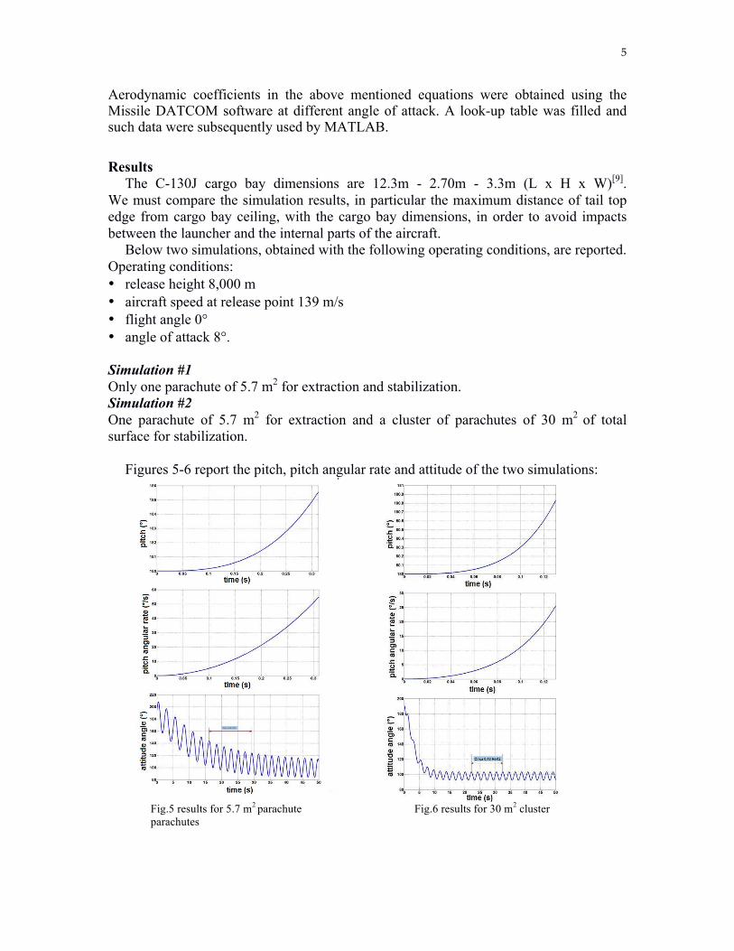
Aerodynamic coefficients in the above mentioned equations were obtained using the Missile DATCOM software at different angle of attack. A look-up table was filled and such data were subsequently used by MATLAB. Results The C-130J cargo bay dimensions are 12.3m - 2.70m - 3.3m (L x H x W)[9]. We must compare the simulation results, in particular the maximum distance of tail top edge from cargo bay ceiling, with the cargo bay dimensions, in order to avoid impacts between the launcher and the internal parts of the aircraft. Below two simulations, obtained with the following operating conditions, are reported. Operating conditions: • release height 8,000 m • aircraft speed at release point 139 m/s • flight angle 0° • angle of attack 8°. Simulation #1 Only one parachute of 5.7 m2 for extraction and stabilization. Simulation #2 One parachute of 5.7 m2 for extraction and a cluster of parachutes of 30 m2 of total surface for stabilization. Figures 5-6 report the pitch, pitch angular rate and attitude of the two simulations:
Fig.5 results for 5.7 m2 parachute Fig.6 results for 30 m2 cluster parachutes

6
Figures 5-6 above, show, as expected, that the cluster of parachutes slower the rotation much more than the single parachute both for rotation and stabilization; moreover, the parachute cluster smoothes the attitude angle oscillations. Equations (5)÷(9) permits to figure out the best launcher orientation in order to safely ignite engines (launcher and cargo do not hit each other). For instance, as reported in figures 7-8, in about 10s the launcher is almost in vertical position hence, taking into account Thrust Vectoring Control deviation angle range, it is possible to define the proper launcher’s engines ignition point, see fig. 9.
Fig. 7 cluster parachutes: altitude vs flight angle Fig. 8 cluster parachutes: altitude vs time
Fig. 9 Release and ignition conditions

7
Conclusions This study provides good preliminary results with regard to the dynamics of separation between aircraft and launcher. Two configurations were analyzed: • one parachute both for extraction and stabilization; • one parachute for extraction and a cluster of parachutes for stabilization.
The cluster parachutes guarantee better dynamical behavior than the single parachute, in terms of small oscillations during the free fall trajectory, which permit a safer ignition condition. Some critical issues related to unfavorable environmental conditions (e.g. disturbances due to gusts of wind that can create side moments) and turbulence-plane coupling will be examined. References [1] C.L. Galliand, Study of the small: Potential for Operational Military Use of Cubesat, 2010, SSC10-III-2 [2] William B. Blake, Missile Datcom Volume I - Final Report , 1988, Technical Report AFWAL-TR-86-3091 [3] G.Webb, A.da Silva Curiel, Is Access To Space Really A Hurdle?, 2008, IAC- 08.B4.5.2 [4] M Sarigul-Klijn, N. Sarigul-Klijn, A Study of Air Launch Methods for RLVs, 2001, AIAA 2001-4619 [5] M Sarigul-Klijn, N. Sarigul-Klijn, G. Hudson, B. McKinney, L. Menzel, E. Grabow, Trade Studies for Air Launching a Small Launch Vehicle from a Cargo Aircraft , 2005, AIAA 2005-0621 [6] Lockheed Martin Aeronautics Company, C-130J Flight Manual, 2009 [7] Fluent 6.3 User Guide, September 2006 [8] P.Cafarella, P.Teofilatto, A.Minotti, 2013, PhD thesis Aviolancio:studio di una configurazione con C-130J AMI [9] Lockheed Martin Aeronautics Company, C-130J Weight and Balance Manual, 2009