dynamic simulation of industrial reformer reactors
TRANSCRIPT
International Journal of Engineering and Technology Volume 2 No. 7, July, 2012
ISSN: 2049-3444 © 2012 – IJET Publications UK. All rights reserved. 1301
Dynamic Simulation of Industrial Reformer Reactors
Wordu, Animia Ajor Department of Chemical/Petrochemical Engineering,
University of Science and Technology, Nkpolu,
Port Harcourt, Nigeria
ABSTRACT
This research focused on mechanistic kinetic model for the upgrading of the low component fractions petroleum naphtha
(generic) of Nigerian reformer reactors. Four main constituent lumps were considered in the synthesis of the rate equations
that describe the mass action velocity for the depletion processes of the feed in the reactors. The reactors under study is a
continuous catalyst reforming stacked reactors, one reactor on top of the other with gravity mobile flow of catalyst from
reactor 1, 2 and 3. The plant design brings to the barest minimum the deactivation of catalyst by the precursors of the
reactions. Energy and component mass balance approach were adopted to develop the dynamic model for the research. The
models were parameterized by benchmarking against industrial reformer plant data. The equations are non-linear intractable
partial differential equations describing the dynamics of the reactors are very stiff to solve. The resolution of the model
equations depends on the obtaining the values of the activation energies for the four lumps chemical species reactions. A
constrained optimization which considers the minimization of the sum of the squares of difference of the objective function
was carried out by integrating the differential equations numerically. The dynamic equations were converted into a set of
ordinary differential equations by applying numerical method of lines (MOL) of finite difference approximation of the spatial
derivatives, and the equations integrated with respect to time. The dynamic equations were resolved using the mat-lab ode
solver-23. The comparison of deviations of dynamic model with the steady state model results showed naphthene 2.2 percent,
paraffin 0 percent, aromatic -1.6 percent and temperature 0.13 percent, which are consistent with the steady state values of
naphthene 3.7 percent, paraffin 0.6 percent, aromatics 1.2 percent and temperature 1.03 percent. A sensitivity analysis carried
out on the open loop of the reactor system showed that the reactor temperature, pressure and activity of the catalyst are the
major variables for striking a balance economically.
Keywords: Dynamic Simulation, Continuous-Catalyst-Stacked-Reactor, Constrain optimization, Four-Lump Kinetics.
1. INTRODUCTION
Global environmental legislation banned the use of lead
compound as an additive for boosting antiknock
properties of premium fuel. Coupled with this stricter
environmental regulation, there has been a consistent
increase in the demand for higher fuel efficiency
standards of engines. These require the use of higher
compression ratio in engines, and therefore motor fuel
with an even greater octane number. These considerations
have continually forced scientist and the refineries toward
research producing high-octane-number products from the
catalytic reformer reactors. This can be achieved by
reforming the petroleum naphtha under more severe
conditions maintaining optimal process parameters.
Gasoline is a valuable finished product of petroleum at
about 19th Century. The demand became great that many
new oil fields were discovered and fundamental
improvements in refining methods developed through
research. Therefore, gasoline served as the fuel for
internal combustion engines and is mostly rated by its
volatility and antiknock qualities. Volatility is a measure
of the ease of vaporization of gasoline in the carburetor
while the measure of antiknock performance of gasoline
is known as its octane number.
Tetra-ethyl-lead (H2CC) Pb4 compound was the most
important additive used in gasoline blending processes. It
greatly increases the octane number but has been found to
contaminate the exhaust gases with poisonous lead oxides
and renders refiners impotent if contacted carelessly. This
primarily led to research of upgrading low petroleum
fractions of which catalytic reforming processes was
developed.
Catalytic reforming is a refining process that uses
adequate operating conditions and appropriate catalysts to
convert low quality naphtha in the presence of hydrogen
into high grade motor fuels, as well as high yields of
aromatic hydrocarbons and liquefied petroleum gas. There
are a number of reforming processes in use but the major
differences between them are in the composition of the
catalyst used in the reactor and the methods of
regenerating the catalyst. The feed for catalytic reforming

International Journal of Engineering and Technology (IJET) – Volume 2 No. 7, July, 2012
ISSN: 2049-3444 © 2012 – IJET Publications UK. All rights reserved. 1302
is naphtha (generic).The boiling range of the feed varies
according to the process and yields needed.
The catalytic reforming process is one process that
converts gasoline-boiling range low-octane hydrocarbons
from paraffin to iso-paraffin and to naphthene, the
naphthene are changed to aromatics without changing
carbon numbers in the molecule. These yields, that is iso-
paraffin and aromatics are high-octane gasoline
components required to fuel automobiles. The choice of
certain process parameters affect the performance of the
reactors such a dehydrogenation are endothermic and very
fast which cause an immediate drop in the reactor
temperature. Preferably, the adiabatic stacked plug flow
reactor is frequently used with intermediate heat
exchangers between the reactors.
The research was based on fundamental principles of
reaction engineering and reactor hydrodynamics. The
model shall predict the dynamics and performances,
particularly the product yield compositions for a wide
variety of designs and operating conditions. The research
focused on a gas-solid reaction system i.e heterogeneous
catalytic reaction. The modeling of the complex chemical
reactions occurring on the surface of the catalyst is the
most intricate part of the overall modeling effort.
Appropriate kinetic modeling of these reactions are
imperative to achieving the desired prediction accuracy of
the model by assuming a homogeneous phase..
A good number of different approaches of varying
degrees of sophistication have been developed in the past
to model the reforming chemistry. Literature show that
Smith (1959), Krane et al (1960), Schulman and Sinfelt
(1981), Kmak, (1972), Kuo and Wei (1969), Marin and
Froment (1982), Ramage (1987), De Pauw and Froment
(1974), were the very earlier researchers that delved into
the study of naphtha (gasoline) catalytic reforming. In
order to reduce the complexity of the model to a
manageable level the number of chemical components are
assigned to a smaller set of kinetic lumps, each composed
of chemical species grouped together. The first significant
attempt at de-lumping petroleum naphtha into different
constituents was attempted by Smith (1959). He
considered naphtha feed to consist of three basic
components namely paraffins, naphthenes, and aromatics.
Also Smith (1959) kinetic catalytic analysis evidently
assumed a homogenous pattern, when in essence the
process is heterogeneous and constant volume operation.
He also assumed that three hydrocarbon classes has the
same number of carbon atoms.
Bommannan et al (1989) employed the simplified model
of Smith (1959) in some recent reformer modeling work.
In a more extensive attempt to model reforming reactions
of whole naphtha, Krane et al (1960). recognized the
presence of various carbon numbers from C6 to C10 as
well as the difference between paraffins, different
components.
Kmak (1972), presented the first endeavour to incorporate
the catalytic nature of the reactions by deriving a reaction
scheme with Hougen-Watson Langumuir–Hinshelwood
type of kinetics. Rate equations derived from this type
explicitly account for the interaction of the chemical
species with the catalyst. In another notable effort,
Ramage, et al (1987), developed a detailed kinetic model
based on extensive studies of an industrial pilot-plant
reactor. The Kmak (1972) model was later refined by
Marin and Froment (1982), who presented the reaction
network for the whole naphtha fractions from C5 to C10.
The network includes 23 pseudo components and used
Hougen-Watson-type rate equations. Marin and Froment,
(1982) and Van Trimpont et al (1988), also conducted
separate studies on C6and C7 a carbon-number fractions,
respectively and developed the corresponding Hougen-
Watson-type rate equations. Various possible reaction
paths way and mechanisms, were systematically evaluated
before choosing the one that best fit the experimental data
on a laboratory scale reactor.
The lumping criterion carried out by Kuo and Wei (1969),
was used to defining kinetic lumps for the complex
reaction system. Kuo and Wei (1969), incorporated the
reaction pathways and rate equations of Marin and
Froment, (1982) and Van Trimpont (1988), mechanistic
insight to a maximum extent within the model. It is
therefore expected that the model got a better prediction
capabilities.
In a more extensive attempt to model reforming reactions
of whole naphtha, Krane et al (1960), recognized the
presence of various carbon numbers from C6 to C10 as
well as the difference between paraffins, different
components. Kmak (1972), presented the first endeavour
to incorporate the catalytic nature of the reactions by
deriving a reaction scheme with Hougen-Watson
Langumuir–Hinshelwood type of kinetics. Rate equations
derived from this type explicitly account for the
interaction of the chemical species with the catalyst.
In another notable effort, Ramage (1987) developed a
detailed kinetic model based on extensive studies of an
industrial pilot-plant reactor. The Kmak (1987), model
was later refined by Marin, who presented the reaction
network for the whole naphtha, fraction from C5 to C10.
The network includes 23 pseudo components and used
Hougen-Watson-type rate equations. Marin and Froment
(1982) and Van Trimpont (1988), also conducted separate
studies on C6 and C7 a carbon-number fractions,
respectively and developed the corresponding Hougen-
Watson-type rate equations. Various possible reaction
paths way and mechanisms, were systematically evaluated

International Journal of Engineering and Technology (IJET) – Volume 2 No. 7, July, 2012
ISSN: 2049-3444 © 2012 – IJET Publications UK. All rights reserved. 1303
before choosing the one that best fits the experimental
data on a laboratory scale reactor.
Taskar and Riggs (1997) catalytic model assumed a quasi-
state, mole and energy balance equations, constant
catalyst activity, axial and radial dispersion effects were
negligible. The uncertainty associated with diffusion
effects in the catalyst pellets was lumped into kinetic rate
parameters. The steady state variation of the chemical
species and temperature were integrated through each
reactor bed.
Wordu and Oboho, (2003) recognized the three chemical
species paraffins, naphthenes and aromatics. They further
adopted a material balance approach with respect to
naphthenes, paraffins, aromatics, hydrogen gas and
enthalpy changes for the four reactions taking place with
respect to space-time. They further assumed that for an
industrial plug flow reactor operating adiabatically,
quantity of heat input q and heat output q is equal to zero.
The results obtained were in agreement with the industrial
plant data obtained from Nigerian reformer reactor,
Alesa-Eleme, Port Harcourt.
Ferchneider and Mege (2004) investigated on fixed bed
reactors with a single fluid phase for reaction processes
catalyzed by a solid phase. They made use of a one-
dimensional model and separately resolved the equation
of conservation of mass and energy, and momentum. The
calculation was based on the multi-dimensional model
and the simultaneous resolution of the local conservation
equations. The reactors they assumed to investigate was
distinguished by their annular geometry and radial
circulation of the Feedstock. The flow of streams in the
reactors was assumed to be axsymmetric. They further
carried out calculation of the hydrodynamics (mean
velocities, pressure), thermal and mass fields
(concentration of each species) serves to identify the
influence of the internal components in two industrial
reactors geometries. Finally, the quantity of coke formed
and deposited on the catalyst surface, was calculated by
the model, and reveals potential areas of weakness in the
research.
Hu and Zhu (2004), presented molecular modeling and
optimization for the naphtha catalytic reforming process;
the molecular modeling approach also focuses on
producing high octane number gasoline by reforming
reactions in three sequencing fixed bed reactors. They
made use of the naphtha consisting of molecules from C5
to C10 including paraffin iso-paraffin, naphthene and
aromatic. The molecular kinetic network consisted of
paraffin cracking, naphthene side-chain cracking,
aromatic side-chain cracking, ring opening, ring closure,
paraffin isomerizations, dehydrogenation and
hydrogenation. Based on this reaction network molecular
model for catalytic reforming was formulated. A process
optimization was performed for feed temperature and
pressure under constraints such as benzene content,
aromatic content, and RON (Research Octane Number)
limitations. This more recent innovation on catalytic
reforming of low boiling point naphtha Feed fraction gave
a final product with the highest profit with respect to
benzene and aromatic contents and RON value. The
application of molecular modeling to optimization in the
process control gave significant benefits. Kubo (2004)
studied on the analysis of catalytic reforming
2. PROCESS AND CHEMISTRY
The process and chemistry are complicated reactions
occurring in series-parallel to each other, forming the
rather complicated overall reaction scheme (Weismann,
1983) indicated in figure 1.
Predominant active sites: A = acid, M = metal. i = hydrocracking and demethylation (m); ii = paraffin isomerization; iii =
dehydrocyclization. Gates, Katzer, Schuit, (1979), gave the main reforming reactions.
iii ii i
Fig.1: Overall Feed conversion scheme in the reactors
N - PARAFFINS
1) M/A
CRACKED
PRODUCTS
2) M/A
ISOPARAFFINS
CYCLOPENTANES
APHTHENE
ISOMERIZATION
DEHYDRO –
GENATION
CYCLOHXANES
DEALKYLATION
AND
DEMETHYLATION
AROMATICS LIGHTER
AROMATICS
M/A
A
A M /A
M/A

International Journal of Engineering and Technology (IJET) – Volume 2 No. 7, July, 2012
ISSN: 2049-3444 © 2012 – IJET Publications UK. All rights reserved. 1304
3. MATERIALS AND METHODS
Appropriate data were determined by estimation using
relevant mathematical models and some were obtained
from literature. The kinetic parameter materials for
applications in the dynamic model resolution are
presented in Tables 1, 2, 3, 4 and 5.
Table 1: Kinetic Parameters Ao, Kp, Kf, Kc and HR for the reactions
Reactions
1, 2, 3 & 4
Parameters
Pre-exponential
constant, Ao
Equilibrium Constant, Kp
Heat of Reaction,
HR Kj/Kmol of
H2 liberated
Conversion of
naphthenes to
Aromatics
1.19 x 10⁸
1.0404 x 10⁶ exp(46.15 – 212700/RT)
70928
Conversion of
paraffins to
naphthenes
4.170 x 10¹³
9.869 x 10³ exp(36950/RT – 712)
- 44185
Naphthenes
cracking
4.5881 x 10¹⁸
-
- 51860
Paraffins cracking
4.5881 x 10¹⁸
-
- 51860
Table 2: Equilibrium Constants, Kp
Reactions Parameters
1, 2, 3 and 4 Equilibrium constant, Kp
Conversion of naphthenes to aromatics RT
21270015.46exp100404.1 6
Conversion of paraffins to naphthene 71236950exp10869.9 3 RT
Naphthenes hydrocracking -
Paraffins hydrocracking -
Table 3: Heat of Reactions, HR
Reactions Parameters
1, 2, 3 and 4 Heat of Reactions, HR, kJ/Kmol of H2 librated
Conversion of naphthenes to aromatics 70928
Conversion of paraffins to naphthene - 44185
Naphthenes hydrocracking - 51860
Paraffins hydrocracking - 51860
Table 4: Arrhenius Constants or Pre-exponential Constants, Ao
Reactions Parameters
1, 2, 3 and 4 Arrhenius Constants, Ao
Conversion of naphthenes to aromatics 1.19 x 10⁸
Conversion of paraffins to naphthene 4.170 x 10¹³
Naphthenes hydrocracking 4.5881 x 10¹⁸
Paraffins hydrocracking 4.5881 x 10¹⁸
Table 5: Steady State Model Predictions and Plant data Reformate Yields, Mole %
Components Plant Data Model Predictions
Naphthenes, N 0.12 0.1156

International Journal of Engineering and Technology (IJET) – Volume 2 No. 7, July, 2012
ISSN: 2049-3444 © 2012 – IJET Publications UK. All rights reserved. 1305
Aromatics, A 0.53 0.5365
Paraffins, P 0.35 0.3479
hydrogen, H2 8.0 8.0
Temperature, T 780 K 772 K
4. REACTION RATE EQUATION
The reaction rate equation gives an expression for the rate
of transformation or depletion of a reactant or formation
of desired product in a given chemical process. The rate
of transformation, conversion or disappearance of a
reactant i to form the product j through the reforming
reactions 1 to 4, (-ri,j)14, (feed converted per unit Fresh
Feed per unit time) in the reformer reactor maintaining a
first-order elementary reactions is given by:
yi
n
ijiji yKr ,,, (1)
w.r.t. mole fraction of reaction species
Since catalyst deactivation is negligible, the function i,j is
therefore dropped in the rate model. The model is then
written w.r.t partial pressure of the components in the
vapour phase in the reformer reactors.
n
ijiji pKr ,, (2)
w.r.t. rate of depletion of feed component i,
we have,
n
ijii
ji PKdt
dNr ,
41
,
(3)
where,
Ki,j = rate constant for the reaction process i,j (s-1)
(-ri,j) = rate of reaction n
iy = mass fraction of the Feed component i
Ni = mole fraction of the feed components i
n = order of reaction i,j
i,j = deactivation function
But, since catalyst deactivation is negligible, the function
i,j is therefore dropped or eliminated in the rate model.
The model is then w.r.t partial pressures of the
components in the vapour phase of the reaction mixtures.
The dependence of the reaction rate constant on
temperature is given by the popular Arrhenius equation
as:
RT
E
joiji
ji
eAK,
,,
(4)
where,
Ki,j = Rate constant for the four reactions
Aoi,j = Frequency or pre-exponential factor or constant.
Ei,j = Activation energy of the reactions
R = Universal gas constant
T = Absolute K
The introduction of this expression into the model
equation makes the model equation intractable non-linear
equations and difficult to solve for the reaction rate
constants Ki,j analytically. Therefore appropriate
numerical method will be applied.
5. KINETIC LUMPS
Oboho, (2005) posited that the reactions taking place in
the reactors follow Lumping Scheme kinetics as shown in
Figure 2. below:
Lumping model of reforming reactions posited by Oboho,
(2005)
Figure 2. Composite Four-lump reforming reactions
Oboho, (2005)
P – Paraffins, N - Naphthenes, A - Aromatics, H2 -
hydrogen, G – Gases, Kc - rate constant for hydro-
cracking, Kf - rate of forward reaction, Kr - rate of reverse
reaction.

International Journal of Engineering and Technology (IJET) – Volume 2 No. 7, July, 2012
ISSN: 2049-3444 © 2012 – IJET Publications UK. All rights reserved. 1306
Four fundamental reactions are identified in this unique
lumping scheme kinetics. The derivation of the rate
equations from the scheme is very crucial for research.
The rate equations will be derived with respect to the
components of the feed naphtha which are Paraffins,
Naphthenes, Aromatics, Hydrogen and Cracked Gases.
These are the constituents of the lumping scheme
considered for the research. Smith,(1959), and Oboho,
(2005) also recognized four major reactions associated
with the rate equations respectively. They are:
Dehydrogenation of naphthenes to form aromatics and
hydrogen
Hydrogenation of aromatics to form paraffins and vice
versa
Hydro-cracking of naphthenes to gases
Hydrocracking of paraffins to gases and Temperature
effects
6. DYNAMIC MODEL
The following derivations are essential for the study of a
typical plug flow reactor system. The equations serve as
the reactor equation for a reformer reactor.
Mathematically, the plug flow reactor equation is stated
thus,
d
RF
V
AAO
1 (5)
But,
AOoAO CF i.e 3
3
.sec m
molesm in terms of
concentration (6)
Substituting equation (6) into (5),to obtain,
d
RC
V
AAOo
1 (7)
Since,
A
AAO
o R
dC
V
(8)
Differentiating equation (8) we have,
A
AAO
R
dCd
(9)
Equation (8) rearranges to,
AO
AA
C
R
d
d
(10)
Equation (10) is the reactor equation in differential form
for a plug flow regime which is required for the research.
Furthermore, considering the fact that the research
focuses on the simulation of an existing reformer process
reactor, appropriate model equations which takes into
account the complex chemical species involved in the
depletion process is paramount. Therefore, the reactor
equation above was differentiated to obtain a summary
equation (10) in differential form which when rearranged
and on substitution of the (-ri) terms for the major
component species i of the depletion processes and the
energy or temperature effects will form the main fabric of
a system of non linear partial differential model equations
for the simulation of the reactor.
Consequently, stating the material balance for element of
volume of a reformer reactor, using the figure 3 below,
we have,
Figure 3: material balance for element of volume of a
reformer reactor
Mathematically,
0 dVrCdCC AAAoAo (11)
0 VdrCd AAo (12)
Rearranging equation (11) we have,
A
A
o r
CddV
(13)
But,
r
Cdd A (14)
C
A
CA + dCA
o
o

International Journal of Engineering and Technology (IJET) – Volume 2 No. 7, July, 2012
ISSN: 2049-3444 © 2012 – IJET Publications UK. All rights reserved. 1307
where,
o
V
(15)
Differentiating equation (15) we have,
o
dVd
(16)
AA r
d
Cd
or A
A rd
Cd
(17)
Equation (17) can be used to substitute the values of the (-
ri) to obtain the various component balance for the
reactions with respect to number of moles of species in
the reactors. e.g
d
Nd N\
T
NP
p
f
HNpHA
p
f
NfP
PKP
K
KPPKPP
K
KPK 3
2
2
2
3
1
1
22 (18)
Where, the right hand side of equation (18) is the required
kinetic model balance for the species with respect to
napthene.
7. BOUNDARY CONDITIONS FOR
ELEMENT OF VOLUME OF A
REFORMER REACTOR
Stating the material balance equation with respect to feed
components naphthenes NN, considering an element of
volume per unit time, elemental volume of a plug flow
reactor is applied to derive the material balance equation.
Thus,
Fig. 6 : Boundary conditions for the reformer reactor model
equations
8. REFORMER REACTOR MODEL
(RRM)
The continuity and energy balance equations are
principally used to develop mathematical models applied
for the study of the reforming of the hydrocarbons
components and temperatures effects of the process. The
reforming reactors is modeled as adiabatic plug flow
reactor operated in series and / or configured in series.
The dynamic studies of the process plant using developed
models will serve as major focus for this research of the
reformer reactors.
9. MATERIAL/ COMPONENT MASS
BALANCE
The process which the low hydrocarbons components (C5,
C6, C7, C8) are transformed and/or upgraded into products
(stable aromatics) will be monitored by the application of
the law of conservation of mass, energy and momentum
on a differential volume element of the reformer reactors
of the Nigerian Petroleum Refinery located at Alesa-
Eleme. But, the law of conservation of momentum has no
relevance in this research; hence it is not emphasized in
z z + dz
Af
z
(t,z) (t,z)
(t,z)
z = 0 z = L
v
z
dv
Fig. 5 : Differential volume element of the reactor for the
conversion of the Feed
dA
FA FA + dA
Af
dv
dL
FA FA + dA
dv
d
A
F
A
FA + dA
FAf , Af
d
L
F
A
O
d
v
Fig. 4: A cross-section of the reactor depicting inflow of
Feed and outflow of products
U
Plug flow
velocity,
International Journal of Engineering and Technology (IJET) – Volume 2 No. 7, July, 2012
ISSN: 2049-3444 © 2012 – IJET Publications UK. All rights reserved. 1308
this work. Therefore, the law of conservation of mass and
energy prevail throughout the research.
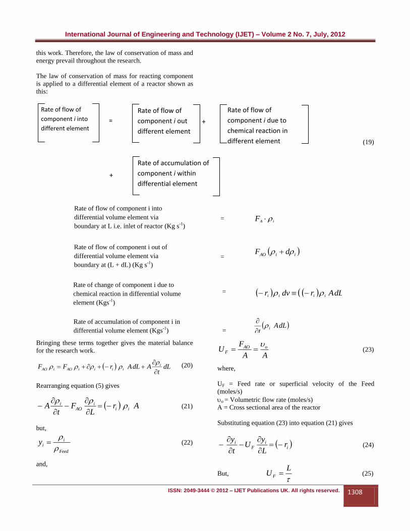
The law of conservation of mass for reacting component
is applied to a differential element of a reactor shown as
this:
Bringing these terms together gives the material balance
for the research work.
dLt
AdLArFF iiiiiAOiAO
(20)
Rearranging equation (5) gives
ArL
Ft
A iii
AOi
(21)
but,
Feed
iiy
(22)
and,
AA
FU oAO
F
(23)
where,
UF = Feed rate or superficial velocity of the Feed
(moles/s)
o = Volumetric flow rate (moles/s)
A = Cross sectional area of the reactor
Substituting equation (23) into equation (21) gives
ii
Fi r
L
yU
t
y
(24)
But,
LU F (25)
Rate of flow of component i into
differential volume element via
boundary at L i.e. inlet of reactor (Kg s-1) iAF
Rate of flow of component i out of
differential volume element via
boundary at (L + dL) (Kg s-1)
iiAO dF
Rate of change of component i due to
chemical reaction in differential volume
element (Kgs-1)
dLArdvr iiii
=
=
=
Rate of accumulation of component i in
differential volume element (Kgs-1) = dLA
ti
Rate of flow of
component i into
different element
Rate of flow of
component i out
different element
Rate of flow of
component i due to
chemical reaction in
different element
Rate of accumulation of
component i within
differential element
= +
+
(19)
International Journal of Engineering and Technology (IJET) – Volume 2 No. 7, July, 2012
ISSN: 2049-3444 © 2012 – IJET Publications UK. All rights reserved. 1309
.FUL (26)
)(.
. i
F
iF
i rU
yU
t
y
(27)
)( iii r
y
t
y
(28)
0)(
i
ii ry
t
y
(29)
)( iii r
y
t
y
(30)
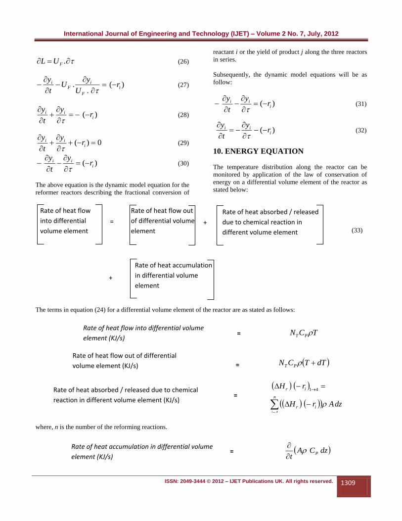
The above equation is the dynamic model equation for the
reformer reactors describing the fractional conversion of
reactant i or the yield of product j along the three reactors
in series.
Subsequently, the dynamic model equations will be as
follow:
)( iii r
y
t
y
(31)
)( iii r
y
t
y
(32)
10. ENERGY EQUATION
The temperature distribution along the reactor can be
monitored by application of the law of conservation of
energy on a differential volume element of the reactor as
stated below:
The terms in equation (24) for a differential volume element of the reactor are as stated as follows:
where, n is the number of the reforming reactions.
Rate of heat accumulation in differential volume
element (KJ/s) = dzCA
tP
Rate of heat absorbed / released due to chemical
reaction in different volume element (KJ/s)
n
i
ir
ir
dzArH
rH
4
41
=
Rate of heat flow out of differential
volume element (KJ/s)
dTTCN PT =
Rate of heat flow into differential volume
element (KJ/s) TCN PT =
Rate of heat flow
into differential
volume element
Rate of heat flow out
of differential volume
element
Rate of heat absorbed / released
due to chemical reaction in
different volume element
Rate of heat accumulation
in differential volume
element
= +
+
(33)

International Journal of Engineering and Technology (IJET) – Volume 2 No. 7, July, 2012
ISSN: 2049-3444 © 2012 – IJET Publications UK. All rights reserved. 1310
dzTACt
TdzACrHdTTCNTCN
p
pirPTpT
41
(34)
Discretization of feed components mole fractions into a system of ODEs
133
2
2
4
2
12
43
42
1
1
11
,01,0)0(
NKPNK
KNPNK
PNNK
KPNK
L
NN
dt
dN
T
p
f
Tf
T
p
f
Tf
zz
(35)
Naphthenes, NN
N = 1
133
2
2
4
2
12
43
42
1
1
11
,11,1)1(
NKPNK
KNPNK
PNNK
KPNK
L
NN
dt
dN
T
p
f
Tf
T
p
f
Tf
ZZ
(36)
Aromatics, NA
N = 2
TfT
p
fzzPNKPNN
K
K
L
NN
dt
dN11
43
42
1
1,21,2)2(
(37)
Paraffins, NP
N = 3
34
2
4123
2
2,31,3)3(NKPNNKPN
K
K
L
NN
dt
dNTfT
p
fzz
(38)
Hydrogen,NH2
dL
dt
TCAd P
dL
dt
TCAdT P
T+dT
T
N
vt
NG Nf
fNf GNG
t
NGNG
Nf
Nf
vt
NG Nf
Fig. 7 : Differential volume of reformer reactor for energy balance

International Journal of Engineering and Technology (IJET) – Volume 2 No. 7, July, 2012
ISSN: 2049-3444 © 2012 – IJET Publications UK. All rights reserved. 1311
N = 4
TfT
p
fZPNKPNN
K
K
L
NN
dt
dN11
43
42
2
22,41,4)4(3
Temperature, T
N = 5
The PDEs were rewritten in terms of the index variable i.
For i = 1, … I + 1, and
t = 1, 2, … t + 1.
The partial differential equations were converted into a set
of simultaneous ordinary differential equations. The
ordinary differential equations have L as the independent
variable and were subsequently solved by popular
conventional means of Runge-Kutta numerical methods.
It is however stated that the ODEs obtained using the
method of lines (MOL) are very stiff and computational
efficiency can be achieved by using an ODE – solver of
the Matlab computer language. Above all, the brevity of
the exercise (matlab) is quite plausible.
11. ESTIMATION OF KINETIC
PARAMETERS Essentially, the reactor model equations developed
contain certain kinetic parameters which are specific for
the Nigerian crude oil fractions for simulation of the
reactor model equations. These are: rate constant, Kf for
the forward reaction, and reverse reaction, Kr, frequency /
pre – exponential factor, activation energies Ei for the
kinetic lumps reactions, equilibrium constant, Kp, rate
constant Kc for the naphthene and paraffin hydro-cracking
reactions. These constants associated with the models
were determined for resolution of thee model equations
using standard numerical technique. The determination of
these constants are imperative as results obtained using
literature values Oboho,(2005) showed conversion and
yield results which gave maximum deviations of
naphthene 2.45%; paraffins 28.5%; aromatics 15.4%;
temperature 1.29% when compared with industrial plant
data. These deviations can be attributed to the difference
in the feed stock properties between that for which the
kinetic parameters were generated and the one being
tested. Frantic effort was made to reach the industrial
process plant for lifting the needed data for resolution of
dynamic models and validation of the results.
The dependence of the reaction rate constant on
temperature is given by the popular Arrhenius equation
as:
RT
E
joiji
ji
eAK,
,,
(41)
where,
Ki,j = Rate constant for the four reactions
Aoi,j = Frequency or pre-exponential factor or constant.
Ei,j = Activation energy of the reactions
R = Universal gas constant
T = Absolute K
The introduction of this expression into the model
equation makes the model equation intractable non-linear
equations and difficult to solve for the reaction rate
constants Ki,j analytically. Therefore, appropriate
numerical solution technique is adopted. The purpose for
this exercise is to be able to estimate the activation
energies, Ei for each of the kinetic lumps while literature
values of Aoi,j will be taken as posited by Bommannan, et
al., (1989).
The frequency or pre-exponential factor or constant is a
function of the molarity of the reaction; but independent
of the catalyst used. However, the values reported by
Bommannam,et al., (1989) were used in this work. The
deactivation constant is lumped into the kinetic
parameters.
Another parameter involved in the reversible reactions is
the equilibrium constant Kp, which can be calculated from
34133
2
22
4123
3
3NK
nNK
nPN
K
KPNNK cc
T
p
f
Tf
111
43
42
1
1,51,553 HPNKPNN
K
K
z
TTCN
dt
dNTfT
p
fzz
pT
43431323
2
22
4123
3
3HNK
nHNK
nHPN
K
KPNNK cc
T
p
f
Tf
(40)
(39)
International Journal of Engineering and Technology (IJET) – Volume 2 No. 7, July, 2012
ISSN: 2049-3444 © 2012 – IJET Publications UK. All rights reserved. 1312
thermodynamic considerations. There are no significant
differences between the values reported in literature
(Smith, 1959), (Bommannam, Srivastava, and Saraf,
1989), (Radosz and Kramarz, 1978), and (Van der Baan,
1980). Various values of the heats of the various
reactions have been reported in literature. However, the
values reported by (Smith, 1959) lie somewhere
intermediate between other reported values and were used
in this work. The values of the various kinetic parameters
used in this work are given in Table 1, while the feed
stock properties and reforming conditions are given in
Table 2.
The activation energies depend on catalyst composition
and in the absence of reliable experimental values can
best be estimated from plant data. A constrained
optimization procedure was used to find the activation
energies that minimized the sum of the squares of the
differences between calculated and experimental values of
dimensionless reactor outlet temperatures and mole
fractions of the various lumps from the third reactor
simultaneously. Data for the mole fractions at the outlet
of the first two reactors were not available and could not
be used in the parameter estimation.
The dimensionless reactor temperature was defined as the
ratio of the outlet temperature to the inlet temperature.
12. OBJECTIVE FUNCTION
The objective function is therefore defined as follows:
m
ij
plantoutcalculatedout
i
planticalculatedi TTNN1
32
3
1
2S (42)
where,
m = number of data sets used
i = 1, 2 and 3 for naphthene, paraffin and aromatic
hydrocarbon respectively
j = 1, 2 and 3 for reactor 1, 2 and 3 respectively.
For assumed value of Ei, Equations 1 to 5 (i.e. the five
model equations developed for the research) were
integrated numerically using matlab ode – 15s solver for
stiff ordinary differential equations to obtain calculated
values of the yields of naphthene, paraffin and aromatic
hydrocarbons at the third reactor outlet and the
dimensionless reactor temperatures.
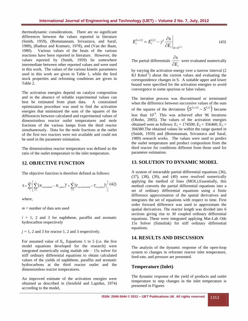
An improved estimate of the activation energies were
obtained as described in (Senifeld and Lapidus, 1974)
according to the model,
zEEi
z
i
z
iE
sEE
1
(43)
The partial differentials
iE
s
were evaluated numerically
by varying the activation energy over a narrow interval (2
KJ Kmol-1) about the current values and evaluating the
correspondence changes in S. A suitable upper and lower
bound were specified for the activation energies to avoid
convergence to some spurious or false values.
The iteration process was discontinued or terminated
when the difference between successive values of the sum
of the squares of the deviations zz SS 1
became
less than 10-9. This was achieved after 96 iterations
(Oboho, 2005). The values of the activation energies
obtained were as follows: E1 = 174500; E2 = 356460; E3 =
394380.The obtained values lie within the range quoted in
(Smith, 1959) and (Bommannan, Srivastava and Saraf,
1989) research works. The values were used to predict
the outlet temperature and product composition from the
third reactor for conditions different from those used for
parameter estimation.
13. SOLUTION TO DYNAMIC MODEL
A system of intractable partial differential equations (36),
(37), (38), (39), and (40) were resolved numerically
applying the method of lines (MOL).Essentially, this
method converts the partial differential equations into a
set of ordinary differential equations using a finite
difference approximation of the spatial derivatives and
integrates the set of equations with respect to time. First
order forward difference was used to approximate the
spatial derivatives. The reactor length was divided into 6
sections giving rise to 30 coupled ordinary differential
equations. These were integrated applying Mat-Lab Ode
15s Solver (Simulink) for stiff ordinary differential
equations.
14. RESULTS AND DISCUSSION
The analysis of the dynamic response of the open-loop
system to changes in reformer reactor inlet temperature,
feed-rate, and pressure are presented.
Temperature (Inlet)
The dynamic response of the yield of products and outlet
temperature to step changes in the inlet temperature is
presented in Figures

International Journal of Engineering and Technology (IJET) – Volume 2 No. 7, July, 2012
ISSN: 2049-3444 © 2012 – IJET Publications UK. All rights reserved. 1313
15. DISCUSSION
15.1 Effect of Temperature on The Dynamics
of the Process
For a dynamic model simulation temperature of 812K,
and pressure of 993 KPa, the mole fractions of naphthene
increased from 0.1261 to a steady state value of 0.1372
after 40 seconds. Whereas, that of aromatics decreased
from 0.5261 to 0.5149 after about 40 seconds, thus,
stability is attained after 40 seconds in reactor 3.
Similarly, the temperature of the reactor 3 decreased from
768 to a steady state value of 771 after about 30 seconds
to attain stability of the process.
Step increase in temperature from 812k to 833k for
pressure of 993 kpa
Dynamic Model Simulation Results: Dependence of
Mole Fractions of Naphthene, Paraffin and Aromatics
with Time – Reactor 3
Fig. 9 : Dependence of mole fractions of naphthene, paraffin
and aromatic on time
Dynamic Model Simulation Results: Dependence of
Mole Fractions of Naphthene, Paraffin and Aromatics
with Time – Reactor 2
Fig. 10 : Dependence of mole fractions of naphthene,
paraffin and aromatic on time
Dynamic Model Simulation Results: Dependence of
Mole Fractions of Naphthene, Paraffin and Aromatics
with Time – Reactor 1
Fig. 11 : Dependence of mole fractions of naphthene,
paraffin and aromatic on time
16. EFFECT OF PRESSURE ON THE
DYNAMICS OF THE PROCESS
Steady state simulation of reactor 3 using the parameters
pressure 9.8 x 101.35 KPa, indicates the mole fractions
of naphthenes and aromatic with temperature 812K
increased from 0.1261 to a steady state value of 0.1372,
while that of aromatic decreased from 0.5261 to 0.5149 to
attain stability of the process. The paraffins maintained a
constant value of 0.3478.
The change of the mole fractions of the components with
time is quite small as to be considered in industrial
practice. Therefore, this is the required pressure range or
plant design pressure. Consequently, this pressure value
assists in the suppression of coke formation and does not
encourage or facilitate equipment wear.
Table 4.19: Dynamic Model Simulation Results:
Dependence of Mole Fractions of Naphthene, Paraffin
and Aromatics with Time – Reactor 3
Fig. 12 : Dependence of mole fractions of naphthene,
paraffin and aromatic on time

International Journal of Engineering and Technology (IJET) – Volume 2 No. 7, July, 2012
ISSN: 2049-3444 © 2012 – IJET Publications UK. All rights reserved. 1314
Dynamic Model Simulation Results: Dependence of
Mole Fractions of Naphthene, Paraffin and Aromatics
with Time – Reactor 2
Fig. 13 : Dependence of mole fractions of naphthene,
paraffin and aromatic on time
Dynamic Model Simulation Results: Dependence of
Mole Fractions of Naphthene, Paraffin and Aromatics
with Time – Reactor 3
Fig. 14 : Dependence of mole fractions of naphthene,
paraffin and aromatic on time
Dynamic Model Simulation Results: Dependence of
Mole Fractions of Naphthene, Paraffin and Aromatics
with Time – Reactor 1
Fig. 15 : Dependence of mole fractions of naphthene,
paraffin and aromatic on time
17. CONCLUSION
A rigorous mathematical model of industrial reformer
reactors operated as a continuous catalyst reforming mode
applying a detailed kinetic scheme was developed. The
kinetic scheme was developed considering four idealize
reactions by employing the lumping scheme method
Wordu and Oboho (2003). The method of lumping the
constituent hydrocarbons fractions into three major class
of naphthene, paraffin and aromatic is for better
management of the process, since the chemistry of the
reforming reactions are quite complex from the point of
view of its research.
The research employed naphtha (generic) naphthene,
paraffin and aromatic as feed, while hydrogen which is
the combined feed functions in two folds which serves to
terminate the reactions of the double bonds formed in
reactor 3, thereby suppresses the formation of coke
through the reactions of the precursors of Sulphur,
Nitrogen etc. during the process. Secondly, hydrogen
facilitates transport of the liquid feed naphtha into the
reaction zone, and maintains the required partial pressure
of the reactors.
The intractable nonlinear model equations for the
dynamic process were partial differential equations. These
are difficult to solve analytically. Therefore, they were
converted to ordinary differential equations utilizing the
MOL i.e method of lines. This implies that the time were
discretised using the finite difference method. This
method aided the resolution of the equations through
numerical method on application of MATlab Simulink
ODEs-23 devices.
The dissertation utilizes the fundamental principles of
energy and component mass balance approach to
formulate the required dynamic model equations. The
model equations were sectionalized into five (5) and make
up to thirty (30) simultaneous ordinary differential
equations. They were resolved numerically to obtain the
expected results.
A simulation procedure which considers the steady state
values as initial conditions were adopted to attain stability
in each of the three reformer reactors 1, 2 and 3.
This is the basis of the present dissertation.
It is important to state that the study focused on
continuous catalyst reforming unit, which operates as a
mobile bed reactor,there is mobile flow of catalyst
through the stacked reactors 1, 2 and 3.
This method of reforming is considered better than the
semi-regenerative catalytic reforming unit which need to
International Journal of Engineering and Technology (IJET) – Volume 2 No. 7, July, 2012
ISSN: 2049-3444 © 2012 – IJET Publications UK. All rights reserved. 1315
be shut down when the activity of the catalyst is brought
to a minimum.
The results of the dynamic models simulations were
calculated values that were benched marked with the plant
data of the Nigerian Port Harcourt Refineries process
plant. The following deviations for dynamic and stead
state models were obtained.
The dynamic model steady state simulations results for
reactors, 3, 2 and 1 gave average value of naphthene 4%,
paraffin 0.09%, aromatics – 6.8% and Temperature
1.83%. Whereas, that of steady state model results are
given as ----Naphthene 3.7%, Paraffin 0.6%, Aromatics
1.2%, and temperature 1.03%.
From the results, it can be observed that the comparison
of the dynamic model and steady states model are in
agreement.The chemical species underwent a progressive
conversion from initial conditions to final value of certain
temperature specific for each of the reactors maintaining
reversible endothermic reactions.
From the dynamic simulations of the reactors, it was
observed that dynamics were from 10 to 80 seconds, for
the reactions processes to stabilize. This can be attributed
to the high activity of the mobile catalyst in the reactors.
Finally the overall conclusion of the dissertation is that
the dynamic studies of the Nigerian reactors would be
expected to result in significant economic benefits when
the process is operated with pressure range of 7 to 14 *
101.35 KPa to achieve economic balance.
REFERENCES
[1] Bommannam, D., Srivastava R. D. and Saraf D. N.
(1989): Modeling of Catalytic Naphtha Reformers,
Canadian Journal of Chemical Engineering, 67, 405.
[2] De Pauw, R.P., and Froment, G. F (1974):
Deactivation of a Platinum Reforming Catalyst in a
Tubular Reactor, Journal of Chemical Eng. Sci., 30,
789.
[3] Ferchneider , G and Mege , P. (2004): Numerical
simulation of Fixed-Bed Catalytic reforming
Reactors: Hydrodynamics/Chemical Kinetics
Coupling. Journal of Oil & Gas Science and
Technology Vol. 48, No. 06.
[4] Gates, B.C; Katzer, J. R, Schuit, G.C.A (1979):
Chemistry of Catalytic Process, McGraw-Hill
Company, New York, P. 284.
[5] Hu. S. and Zhu X.X. (2004): Molecular Modeling
and Optimization for Catalytic Reforming. Journal of
Chemical Engineering Communications, Vol. 191,
No. 4, pp 500-512 (13).
[6] Krane, H. G., Groh A. B., Schulman B. L. and
Sinfelt J. H. (1960): Reactions in Catalytic Reforming
of Naphtha, World Petroleum Congress.
[7] Kmak, W.P. (1972): A Kinetic Simulation Model of
the Power reforming Process, Journal of American
Institute of Chemical Eng. Meeting Housting , Tx.
[8] Kuo, J. W. and Wei J. (1969): A Lumping Analysis
in Monomolecular Reactions Systems, Journal of
Industrial Engineering Funda., 8, 124.
[9] Marin, G. B and Froment G. F. (1982): Reforming of
C6 Hydrocarbons on a Pt-Al2O3 Catalyst, journal of
Chemical Engineering Science 37 (5), 759.
[10] Marin, G. B, Froment G. F., Lerou J. J. and De
Backer W. (1983): Simulation of a Catalytic Naphtha
Reforming Unit, Journal of EFCE Publication Ser.,
Vol. II, No. 27, C117, Paris.
[11] Radosz, M. and Kramarz, J. “To predict catalytic
reformer yield”, Hydrocarbon processing, Vol. 57,
201, 1978.
[12] Shuichi Kubo (2004): Analysis of catalytic reforming
characteristics of various Hydrocarbons, JSAE
Annual congress No. 43 -04,
[13] Seinfelt J. H. and Lapidus, L., Mathematical Methods
in chemical Engineering, Vol. 3 – process Modelling,
Estimation and Identification, Prentice Hall, 388,
1974.
[14] Seinfelt, J. H. and Schulman (1981): Catalytic
reforming of Hydrocarbons in: Catalysis: Journal of
Science and technology, Vol. 1. (J.R Anderson and
M. Boudart, Eds.) Springer – Verlag, New York, P.
257.
[15] Smith, R. B.(1959): Kinetic Analysis of Naphtha
Reforming with Platinum Catalyst, Journal of
Chemical Engineering Progress. 55(6), 76.
[16] Smith, J. M. Van Mess, H. C. Abott, M. M. (2001)
Introduction to Chemical Engineering
Thermodynamics, 6th edition. Tata McGraw – Hill,
Publishing Company Limited New Delhi, pp. 116 –
125.
[17] Ramage, M.P., Graziani, K.R., Schipper, P.H.,
Krambeck, F.J., and B . C. Choi, (1987) : KINPTR

International Journal of Engineering and Technology (IJET) – Volume 2 No. 7, July, 2012
ISSN: 2049-3444 © 2012 – IJET Publications UK. All rights reserved. 1316
(Mobil’s Reforming Model), A Review of Mobil’s
Industrial Process Modeling Philosophy. Journal of
Advance Chemical Eng, 13, 193.
[18] Oboho, E. O. (2005) Estimation of Activation
Energies for the Simulation of an Industrial Catalytic
Naphtha Reformer. Journal of International Journal
of Science and Technology (IJST), Vol.1 & 2, pp. 23
– 28.
[19] Taskar, U. (1996): Modeling and Optimization of a
Naphtha Reformer, Ph.D Diss., Texas Tech.
University, Lubbock.
[20] Unmesh Taskar and James B. Riggs (1997):
Modeling and Optimization of a Semiregenerative
Catalytic Naphtha Reformer, Journal of American
Institute of Chemical Engineer 740 Vol. 43, No. 3.
[21] Van der Baan, H. S., “chemical and chemical
Engineering of catalytic processes”, R. Prins and G.
C. A. Schuit, Eds., Sijthoff and Noordhoff, 1980.
[22] Van Trimpont, P. A., Marin G. B. and Froment G. F.
(1988): Reforming of C7 Hydrocarbons on a Sulfided
Commercial Pt/Al2O3 Catalysts, Journal of
Industrial Engineering Chem. Res. 27 (1).
[23] Wordu, A. A. (2003): Modeling and Simulation of
petroleum naphtha reforming, M.Tech Thesis Rivers
State University of Science and Technology, Port
Harcourt, Nigeria.
NOMENCLATURE
= Feed rate moles / second
= Moles of Feed components per moles of fresh feed per second
= Moles of Hydrogen in the reaction moles / second
= Superficial velocity of the Feed moles / second
= Volumetric flowrate of Feed moles / second
A = Aromatics
Ac = Cross sectional areas in meters
CA = Concentration of Aromatic in the Feed moles / second
CB = Concentration of reacting species moles/dm3
CC = Concentration of products moles/dm3
CD = Concentration of products moles/dm3
CF = Total concentration of the Feed component moles / second
CN = Concentration of Naphthene in the Feed moles / second
CP = Concentration of Paraffin in the Feed moles / second
FA = molar flow rate of pure A for fractional conversion αA.
FAo = molar flow rate of completely unconverted Feed into the reactor moles/ second
G = Cracked gases
H = Hydrogen gas
Kp = Equilibrium constant for the reaction.
Kc = Rate constant hydrocracking reaction
Kf = rate constant for forward reaction
Kr = rate constant for reverse reaction
N = Naphthenes
NA = Moles of Aromatic component in the Feed moles / second
NN = Moles of Napthene component in the Feed moles / second
Np = Moles of Paraffin component in the Feed moles / second
Ntotal = Total number of moles
P = Paraffins
Pa = Pressure in Pa or atmospheres
PA = Partial pressure of aromatics Pa
PN = Partial Pressure of Naphthenes Pa
FG
ir
sec.feedfreshofmoles
Nmoles N
2HN
FU
Fov ,

International Journal of Engineering and Technology (IJET) – Volume 2 No. 7, July, 2012
ISSN: 2049-3444 © 2012 – IJET Publications UK. All rights reserved. 1317
Pp = Partial Pressure of Parafins Pa.
Ptotal = Reactor total Pressure or system total pressure
r2 = rate of backward reaction moles/seconds
RA = rate of chemical reaction moles/second
ri = rate of forward reaction moles/seconds
t = Element of time in second
T = Temperature oC or K
Vo = Volumetric flow rate m3/sec
y = Space-time in the reactor S-1
yi or Ni = Mole fraction of component i, NA, Np, NN, NH2, Ngases
z = Elemental distance in differential volume element meters
αA = Fractional conversion at inlet of the elemental volume
αA+d αA = Fractional conversion at outlet of the elemental volume
αAf = Final friction at the outlet of reactor
αAo = Fractional conversion at time = 0
APPENDIX
Continuous Catalyst Reforming Reactor Units
Continuous Catalyst Reformer Reactor Unit