dynamic vibration analysis and tribological study of
TRANSCRIPT
457
Dynamic Vibration Analysis and Tribological Study of
Mechanical Heat Generation Inside the Superconducting Coil
for Maglev∗
Hiroshi SEINO∗∗, Masaru IWAMATSU∗∗, Toshiki HERAI∗∗, Yasuhiro YOSHINO∗∗∗
and Takashi YAMAMOTO∗∗∗∗
The purpose of this study is to reduce a mechanical heat load which is generated insidethe on-board superconducting coil (SC-coil) for JR MAGLEV. The mechanical heat gener-ation inside the SC-coil-installed inner vessel was investigated on the assumption that it isgenerated by the friction caused by the relative microscopic slips between the SC-coil andcoil fasteners. SC-coil vibration tests and FEM analysis were performed to study the correla-tion between SC-coil vibration and mechanical loss (dynamic vibration analysis). A frettingwear test was performed at liquid-helium-cooled boundaries between structural componentsof the SC-coil (tribological study). The results of dynamic vibration analysis suggest thatthe frictional heat occurs in the surrounding area of the support columns in the rigid bodyvibration mode and in the areas where the greatest degree of bending is observed in the eigen-mode of SC-coil twisting which involves elastic deformation. In the tribological study, testresults demonstrated a high possibility that the mechanical loss inside the SC-coil-installedinner vessel had occurred on the boundary between the epoxy-impregnated SC-coil and coilfasteners.
Key Words: Maglev, Superconducting Coil, Vibration, Fretting, Liquid Helium, HeatGeneration
1. Introduction
In the JR MAGLEV system, trains are operated by theelectrodynamic force between ground coils and on-boardsuperconducting magnets (SCMs). When a train runs,SCMs are vibrated by the electromagnetic disturbancewhich occurs when the train passes over ground coils.This phenomenon generates a heat load in the SCM cryo-genic equipment. The frequency of vibration increasesfrom 0 to 309 Hz corresponding to the vehicle speedof 0 to 500 km/h. In this MAGLEV system, helium isre-liquefied from evaporated refrigerant by an on-board
∗ Received 7th January, 2004 (No. 04-4004)∗∗ Maglev System Development Department, Railway Tech-
nical Research Institute, 2–8–38 Hikari-cho, Kokubunji-shi, Tokyo 185–8540, Japan. E-mail: [email protected]
∗∗∗ Department of Mechanical Enginering, Iwate University,4–3–5 Ueda, Morioka-shi, Iwate 020–8515, Japan
∗∗∗∗ Department of Mechanical Systems Engineering, TokyoUniversity of Agriculture & Technology, 2–24–16 Naka-cho, Koganei-shi, Tokyo 184–8588, Japan
helium refrigeration system. The power of 1 000 watt isnecessary to re-liquefy the amount of helium that is evap-orated by the heat load of 1 watt at 4 K(1). Therefore, de-crease of heat load at 4 K is a very important factor for thedevelopment of JR MAGLEV.
The dynamic heat load in the SCM can be divided intotwo components; an electromagnetic loss and a mechani-cal loss(2). The electromagnetic loss is caused by the eddycurrent which is induced on the surface of inner vessel.This problem was solved by adjusting electrical resistivityof the inner vessel surface and a radiation shield plate(3).The mechanical loss is classified into two. One is that atthe SC-coil and the other that at other parts such as liquidhelium tank and liquid helium transfer piping that con-nects the tank and the inner vessels. The mechanical lossinside the SC-coil-installed inner vessel has been consid-ered as a major cause to increase the mechanical dynamicheat load in the SCM(3) – (5).
A heat load at 4 K was ordinarily measured as the he-lium evaporation from the 4 K cryostat. There was no dif-ference in the vibration dependence of the increase in the
JSME International Journal Series C, Vol. 47, No. 2, 2004

458
helium evaporation between energized and de-energizedstates in vibration tests(5). In the development of JRMAGLEV system, the mechanical loss inside the innervessel has been evaluated by the vibration test results ofthe SC-coil which loaded with a purely mechanical lat-eral force by using a hydraulic servo actuator(1), (2). Theeigen-vibration modes of the SC-coil which involve elas-tic deformation such as bending or twisting were stronglyrelated to the increases in the mechanical heat genera-tion in lateral vibration(2). Therefore, SC-coil deforma-tion caused by vibration is applied to the evaluation of theamount of mechanical heat generation. One example isshown in Ref. (6). The SC-coil deformation expressed bythe eigen-vibration modes of bending or twisting is ob-tained by summing up the amplitudes at the typical spotson the circumference of the SC-coil. It has been surmisedthat the mechanical heat generation inside the inner ves-sel is occurred by the friction caused by the relative mi-croscopic slips between the SC-coil and coil fasteners(5).However, the mechanism of heat generation has not beenstudied sufficiently and needs to be investigated further.
2. Purpose of This Study and a Method of Approach
The first approach of this study is to investigate thecorrelation between SC-coil vibration and increment ofheat load. SC-coil vibration tests and an FEM analysiswere performed to study the relation between SC-coil vi-bration and mechanical heat generation.
The second approach is a fretting test to evaluate thefrictional heat which is generated between the SC-coilstructural components. The fretting test was performedby immersing SC-coil samples in liquid helium.
3. Dynamic Vibration Analysis
In this study, test results were progressively evaluatedto find the heat generation area inside the inner vessel.Two types of SC-coil vibration tests under different con-ditions were performed to investigate the correlation be-tween SC-coil vibration and mechanical heat generation.One was a vertical SC-coil vibration test in the rigid bodyvibration mode and the other was a lateral SC-coil vibra-tion test in the eigen-mode of SC-coil twisting which in-volved elastic deformation.
3. 1 Results of SC-coil vibration testA mechanical vibration test for the SC-coil-installed
inner vessel was performed under several fixing condi-tions.
There are no conspicuous SC-coil deformation in thevertical vibration mode. The relation between verticalSC-coil vibration and the increment of heat load was eval-uated from the standpoint of SC-coil vertical load whichwas input from support columns. A weighted-frequencytotal load (FTL) on the SC-coil was used for evaluation.FTL was defined by using the Eq. (1) at the maximum
vertical SC-coil displacement with the evaluating pointson a SC-coil shown in Fig. 1.
FTL=ωn∑
i=1(aiki) (1)
FTL : Weighted Frequency Total Loadai : Vertical vibration amplitude at the support col-
umnki : Vertial spring constant of the support columnω : Angular velocityFigure 2 shows the FTL dependence of the increment
of heat load for whole fixed support columns and underthe condition that support columns were partly removedin vertical SC-coil vibration tests. There was almost thesame tendency between the FTL and the mechanical lossfor various SC-coil supporting conditions. The mechani-cal loss increased according to the square of FTL. This re-sult suggests that the increment of heat load (=mechanicalloss) was generated from the load transmitted from sup-port columns to the SC-coil.
Lateral vibration test results for the SC-coil-installedinner vessel under the eigen-mode of SC-coil twistingare compared between the two supporting conditions inFig. 3. To laterally connect the inner and outer vessels
Fig. 1 Evaluation points for weighted-frequency total load onthe SC-coil-installed inner vessel
Fig. 2 Increment of heat load versus weighted-frequency totalload on an SC-coil
Series C, Vol. 47, No. 2, 2004 JSME International Journal

459
Fig. 3 A comparison of vibration test results under two fixingconditions in the eigen-mode of SC-coil twisting
Fig. 4 Evaluating points on an SC-coil for averaged twistingvelocity (ATV)
of the SCM of the Yamanashi test vehicle, eight support-ing columns are used, four each arranged inside and out-side the race-track-shaped SC-coil, of which only outsideor inside columns were used in the lateral vibration test,to evaluate the relation between elastic deformation ofSC-coil and heat generation under different SC-coil fixingconditions. The abscissa indicates the averaged twistingvelocity (ATV) obtained by the sum of the amplitudes attypical spots on the circumference of the SC-coil. ATVwas defined as the index of elastic twisting of SC-coilby using the Eq. (2). Evaluating points on the SC-coilfor ATV calculation are shown in Fig. 4. The evaluatingpoints of ATV consist of apexes of a rectangular whoseheight and length are about 0.6 m and 0.5 m, respectively,on the straight parts of the race-track-shaped SC-coil.
ATV =ωl1+ l3− (l2+ l4)
4(2)
ATV : Averaged twisting velocityli : Lateral vibration amplitude at the evaluation
pointsω : Angular velocityThe mechanical loss increased according to ATV lin-
early. The sensitivity of heat generation to the SC-coiltwisting with outside-supports is larger than that withinside-supports when compared at the same twisting de-
Fig. 5 Examples of SC-coil stress distributions under variousSC-coil support conditions
formation in ATV. The increment of heat load under theoutside-support-fixed condition was about 10 times thatunder the inside-support-fixed condition.
3. 2 Discussions of the heat generation areaIt is assumed in discussions that the mechanical heat
generation inside the inner vessel is occurred by the fric-tion between the SC-coil and coil fasteners. The heat gen-erating area inside the inner vessel was found on the as-sumption that the calculated stress at junctions betweenthe SC-coil and coil fasteners shows the level of frictionalmicroscopic slips that were generated by the relative forcebetween the SC-coil and coil fasteners.
A static structural analysis of FEM including the ver-
JSME International Journal Series C, Vol. 47, No. 2, 2004
460
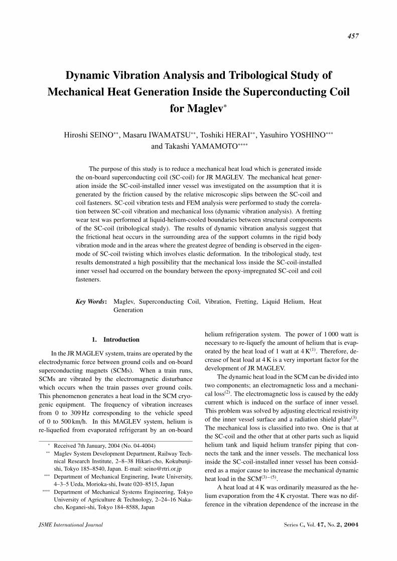
Fig. 6 A comparison of analysis results between two fixingconditions in the eigen-mode of SC-coil twisting
tical acceleration of rigid body vibration was performedto find the heat generating area inside the inner vessel(7).This analysis corresponds to a vertical SC-coil vibrationtest. The FEM analysis model consisted of an inner ves-sel, the SC-coil and coil fasteners under rigid connection.The support columns of the SC-coil were substituted withthree-dimensional spring elements which have the mea-sured stiffness. The equivalent stress was used to evaluatethe frictional force, for the reason that the boundary con-dition of the microscopic slips has not been clarified.
Examples of SC-coil stress distributions for variousSC-coil support conditions are shown in Fig. 5. An anal-ysis result suggests that the frictional heat occurs in thesurrounding area of the support columns. The validity ofthe SC-coil stress distribution analysis to estimate the heatgenerating area was examined by comparing the analy-sis and vertical SC-coil vibration test results between thestandard and additionally reinforced inner vessels(7). Anadditional plate was prepared to reinforce the inner vesselbased on the result of stress distribution analysis, and thereduction of heat generation was examined by performinga vertical SC-coil vibration test. The results of examina-tion prove the validity of the SC-coil stress distributionanalysis.
A dynamic structural analysis of FEM was performed
under two fixing conditions which correspond to the lat-eral vibration test. In the analysis results, distributions ofshear stress were almost the same between these two fixedconditions. However, the difference of stress distributionwas found in the tangential stress between the outside andinside support-fixed conditions. Figure 6 shows a com-parison of analysis results between two fixing conditionsunder the same ATV of outside and inside support-fixingconditions. ATV corresponds to about 0.25 m/s when theSC-coil vibrated at 200 Hz. With inside-supports, the tan-gential stress at arcs was larger than that at other parts ofthe SC-coil. On the other hand, the tangential stress hadpeaks at the joints of straight and curved parts when theSC-coil was fixed with outside-supports. These stresseswere generated by the local bending of the SC-coil. Theseresults suggest that the frictional heat occurs in the areaswhere the greatest degree of bending is observed in theeigen-mode of SC-coil twisting.
4. Tribological Study
A tribological test was performed by immersingSC-coil samples in liquid helium to evaluate the frictionalheat which was generated between SC-coil structural com-ponents. Tribological studies on structural materials ofSC-coil immersed in liquid helium reported about fric-tional properties in superconducting magnet winding, andthe stability of large superconducting magnet(8), (9). Inthese studies, however, samples were slid for a unidirec-tional or large sliding distance, or at a low sliding velocity.In contrast, sliding amplitudes of 10 to 30 microns at thefrequency of 100 to 300 Hz were applied in this study toobtain fretting properties at the boundary between super-conducting coil structural components.
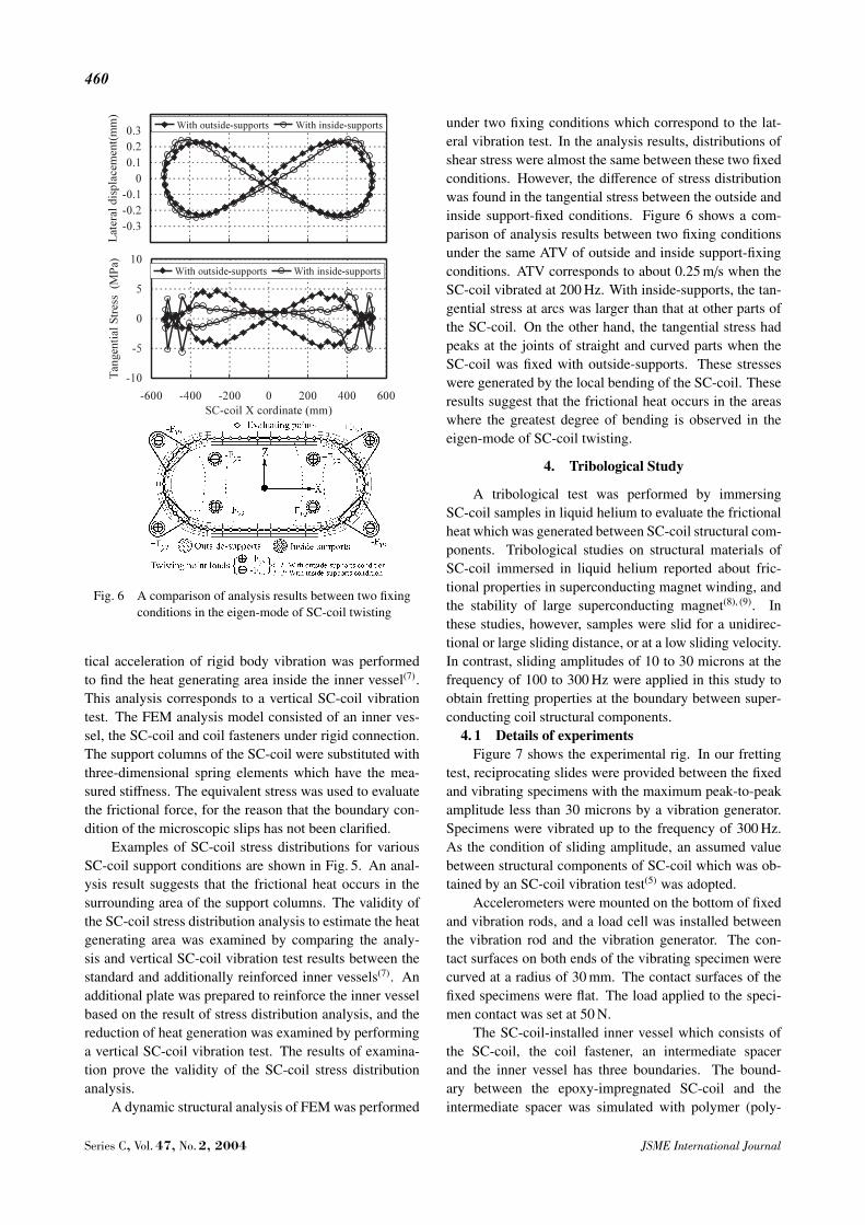
4. 1 Details of experimentsFigure 7 shows the experimental rig. In our fretting
test, reciprocating slides were provided between the fixedand vibrating specimens with the maximum peak-to-peakamplitude less than 30 microns by a vibration generator.Specimens were vibrated up to the frequency of 300 Hz.As the condition of sliding amplitude, an assumed valuebetween structural components of SC-coil which was ob-tained by an SC-coil vibration test(5) was adopted.
Accelerometers were mounted on the bottom of fixedand vibration rods, and a load cell was installed betweenthe vibration rod and the vibration generator. The con-tact surfaces on both ends of the vibrating specimen werecurved at a radius of 30 mm. The contact surfaces of thefixed specimens were flat. The load applied to the speci-men contact was set at 50 N.
The SC-coil-installed inner vessel which consists ofthe SC-coil, the coil fastener, an intermediate spacerand the inner vessel has three boundaries. The bound-ary between the epoxy-impregnated SC-coil and theintermediate spacer was simulated with polymer (poly-
Series C, Vol. 47, No. 2, 2004 JSME International Journal
461
Fig. 7 Schematic diagram of experimental rig for fretting tests
imide tape) and copper. The boundary between the in-termediate spacer and the coil fastener was simulated withcopper and stainless steel (SUS). The boundary betweenthe coil fastener and the inner vessel was simulated withSUS and SUS.
Displacements of fixed and vibration rods were cal-culated from the accelerometer output by double integra-tion. The relative displacement hereafter is the differencein between. The tangential force which acted on frictionalsurfaces between fixed and vibrating specimens was cal-culated by subtracting the inertia of the vibration rod fromthe load cell output.
The amount of helium gas evaporation from theDewar vessel was measured by using a mass flowmeterduring vibration. Heat generation caused by vibration wasindicated by the increase in the volume of helium evapo-ration when a specimen was vibrated.
4. 2 Results of fretting test at liquid-helium-cooledboundaries
Fretting phenomena can be classified as those in thestick region, stick-slip (partial slip) region and gross slipregion. The results of our fretting test were evaluated inthe stick and stick-slip regions by the tangential force ver-sus displacement curve (hysteresis curve).
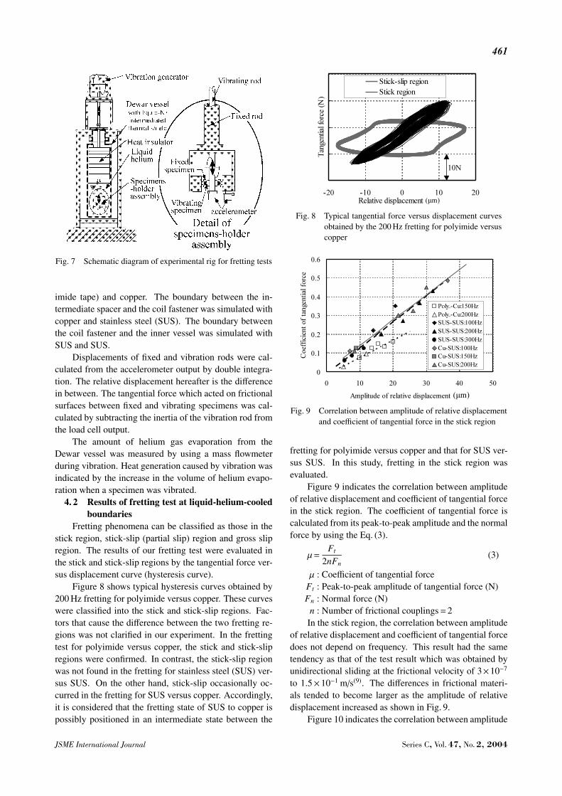
Figure 8 shows typical hysteresis curves obtained by200 Hz fretting for polyimide versus copper. These curveswere classified into the stick and stick-slip regions. Fac-tors that cause the difference between the two fretting re-gions was not clarified in our experiment. In the frettingtest for polyimide versus copper, the stick and stick-slipregions were confirmed. In contrast, the stick-slip regionwas not found in the fretting for stainless steel (SUS) ver-sus SUS. On the other hand, stick-slip occasionally oc-curred in the fretting for SUS versus copper. Accordingly,it is considered that the fretting state of SUS to copper ispossibly positioned in an intermediate state between the
Fig. 8 Typical tangential force versus displacement curvesobtained by the 200 Hz fretting for polyimide versuscopper
Fig. 9 Correlation between amplitude of relative displacementand coefficient of tangential force in the stick region
fretting for polyimide versus copper and that for SUS ver-sus SUS. In this study, fretting in the stick region wasevaluated.
Figure 9 indicates the correlation between amplitudeof relative displacement and coefficient of tangential forcein the stick region. The coefficient of tangential force iscalculated from its peak-to-peak amplitude and the normalforce by using the Eq. (3).
µ=Ft
2nFn(3)
µ : Coefficient of tangential forceFt : Peak-to-peak amplitude of tangential force (N)Fn : Normal force (N)
n : Number of frictional couplings=2In the stick region, the correlation between amplitude
of relative displacement and coefficient of tangential forcedoes not depend on frequency. This result had the sametendency as that of the test result which was obtained byunidirectional sliding at the frictional velocity of 3×10⁻⁷
to 1.5×10⁻¹ m/s(9). The differences in frictional materi-als tended to become larger as the amplitude of relativedisplacement increased as shown in Fig. 9.
Figure 10 indicates the correlation between amplitude
JSME International Journal Series C, Vol. 47, No. 2, 2004

462
of relative displacement and heat generation in the stick re-gion. The amount of heat generation caused by the frettingfor stainless steel (SUS) versus SUS (SUS-SUS) or cop-per versus SUS (Cu-SUS) was almost nil. However, thatfor polyimide versus copper (Poly.-Cu) increased whenthe amplitude of relative displacement was over 10 mi-crons. Especially for 150 Hz fretting of polyimide versuscopper, it is confirmed that the amount of heat generationcaused by the fretting increased as the amplitude of rela-tive displacement increased when the amplitude of relativedisplacement was over 10 microns.
4. 3 Discussion of frictional heat generationFrictional properties of the contact area for a metal
versus another metal fretting and polyimide versus copperfretting were considered by Mindlin’s theoretical equa-tions(10) with Hertz’s contact radius(11). In the fretting ofa metal and another metal, the frictional coefficient at thecontact area was thought to be over 20 times that in thefretting of polyimide versus copper under the same nor-mal force-added condition. In our test results, however,the coefficient of tangential force for a metal versus an-other metal fretting was only 1.5 times that of polyimideversus copper fretting. The difference between calcula-
Fig. 10 Correlation between amplitude of relative displace-ment and heat generation in the stick region
Fig. 11 Frictional properties considered at the contact area fora metal versus another metal and polyimide versus cop-per fretting
tion and test results could have been caused by proper-ties of experimental rig. Figure 11 shows the frictionalproperties at the contact areas for metal versus metal andpolyimide versus copper frettings which were consideredfrom the correlation between test results and calculatedfrictional coefficient. From this consideration, it is possi-ble that specimens slip relatively in the fretting of poly-imide versus copper. In contrast, this is not the case in thefretting of a metal versus another metal.
Fretting test results and consideration of frettingproperties suggest that the mechanical heat generation in-side the SC-coil-installed inner vessel has occurred at theboundary between epoxy-impregnated SC-coil and coilfastener.
5. Conclusions
In this study, the mechanical heat generation insidethe SC-coil-installed inner vessel was investigated by dy-namic vibration analysis and tribological experiments.
In the dynamic vibration analysis, SC-coil vibrationtests and SC-coil stress distribution analysis were per-formed to evaluate the relation between SC-coil vibrationand mechanical heat generation. The SC-coil stress distri-bution analysis was based on an assumption that the me-chanical heat generation is occurred by the friction causedby the relative microscopic slips between the SC-coil andcoil fasteners. The analysis results suggest that the fric-tional heat occurs in the surrounding area of the supportcolumns in the rigid body vibration mode and in the areaswhere the greatest degree of bending is observed in theeigen-mode of SC-coil twisting.
In the tribological experiment, fretting tests were per-formed by immersing SC-coil samples in liquid heliumto evaluate the frictional properties of SC-coil structuralcomponents. The test results demonstrated a high possi-bility that the mechanical loss inside the SC-coil-installedinner vessel had occurred at the boundary between theepoxy-impregnated SC-coil and coil fasteners.
Acknowledgment
Part of this study is financially supported by the Min-istry of Land, Infrastructure and Transport, Japan.
References
( 1 ) Terai, M., Inadama, S., Tsuchishima, H., Suzuki, E.and Okai, T., Development of New SuperconductingMagnets for the Yamanashi Test, Proc. of Maglev ’95,(1995), pp.267–273.
( 2 ) Suzuki, E., Heating Phenomena in the Super-Conduct-ing Magnet of a Maglev Vehicle Caused by Electro-magnetic Vibration, Cryogenics, Vol.37, No.7 (1997),pp.363–370.
( 3 ) Jizo, Y., Akagi, H., Yamaguchi, T., Terai, M. andShinobu, M., Heat Load Characteristics and NewDesign Using One-Coil Model Superconducting Mag-nets, Cryogenics, Vol.37, No.7 (1997), pp.371–379.
Series C, Vol. 47, No. 2, 2004 JSME International Journal

463
( 4 ) Ohmori, J., Nakao, H., Yamashita, T., Sanada, Y.,Shudou, M., Kawai, M., Fujita, M., Terai, M. andMiura, A., Heat Load Tests of Superconducting Mag-nets Vibrated Electromagnetically for the MaglevTrain, Cryogenics, Vol.37, No.7 (1997), pp.403–407.
( 5 ) Suzuki, E., Saito, S., Ohmori, J., Oki, M. and Suzuki,F., Characteristics of Heating in a Mechanically Vi-brated Superconducting Coil, Cryogenics, Vol.37, No.6(1997), pp.287–292.
( 6 ) Yamaguchi, T., Jizo, Y., Akagi, H., Terai, M., Igarashi,M. and Shinobu, M., Vibration Characteristics and Me-chanical Heat Load of Superconducting Magnet of Ma-glev, Proc. of Maglev ’98, (1998), pp.244–249.
( 7 ) Seino, H., Kurihara, M., Herai, T. and Suzuki, E.,
Study of the Mechanical Heat Generation Inside theInner Vessel Installed with a Superconducting Coil,Cryogenics, Vol.42, No.6 (2002), pp.371–376.
( 8 ) Iwabuchi, A., Honda, T. and Tani, J., TribologicalProperties at Temperatures of 293, 71 and 4 K in Fret-ting, Cryogenics, Vol.29, No.2 (1989), pp.124–131.
( 9 ) Kensley, R.S. and Iwasa, Y., Frictional Properties ofMetal Insulator Surfaces at Cryogenic Temperatures,Cryogenics, Vol.20, No.1 (1980), pp.25–36.
(10) Mindlin, R.D. and Deresiewicz, H., Elastic Spheres inContact Under Varying Oblique Forces, J. Applied Me-chanics, Vol.16, No.7 (1949), pp.327–330.
(11) Timoshenko, S.P. and Goodier, J.N., Theory of Elasity,(1970), p.412, McGraw Hill.
JSME International Journal Series C, Vol. 47, No. 2, 2004