dynamics of near-limit cool flames -...
TRANSCRIPT

Yiguang Ju
Princeton University
Dynamics of Near-Limit Cool Flames
The 1st International Workshop on Near Limit Flames
June 21 – 23, 2017Boston University
1

Sang Hee Won
Associate professor,
Univ. South Carolina
Wenting Sun
Assistant professor,
Georgia Tech
Prof. Chae Hoon SohnSejong University
Chris Reuter
Graduate student
Acknowledgement
Omar Yehia
Graduate student
Weiqi Sun
Graduate student
Rui Zhang
Visiting Scholar
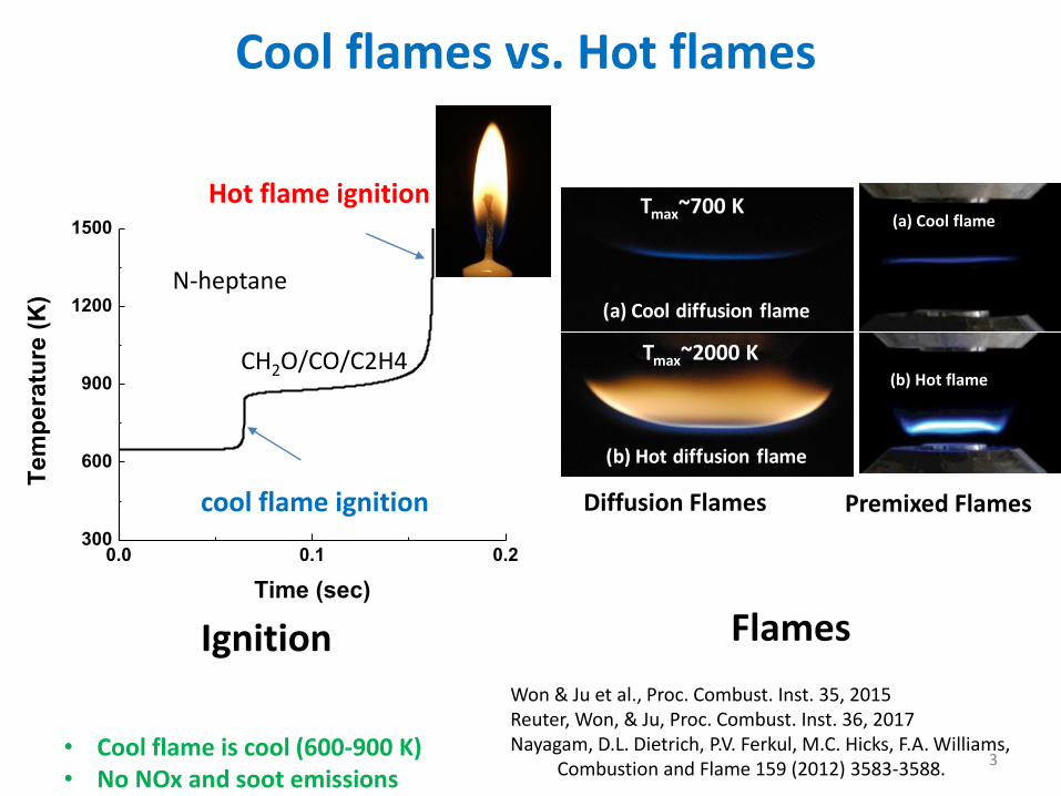
500-950 K
1300-2200 K
0.0 0.1 0.2300
600
900
1200
1500
Te
mp
era
ture
(K
)
Time (sec)
cool flame ignition
Hot flame ignition
N-heptane
Ignition Won & Ju et al., Proc. Combust. Inst. 35, 2015Reuter, Won, & Ju, Proc. Combust. Inst. 36, 2017Nayagam, D.L. Dietrich, P.V. Ferkul, M.C. Hicks, F.A. Williams,
Combustion and Flame 159 (2012) 3583-3588.
(b) Hot diffusion flame
(a) Cool diffusion flame
Diffusion Flames
Tmax~700 K
Tmax~2000 K
Premixed Flames
(a) Cool flame
(b) Hot flame
Flames
Cool flames vs. Hot flames
CH2O/CO/C2H4
3• Cool flame is cool (600-900 K)• No NOx and soot emissions

1. Dynamics and Regimes of Premixed Cool Flames
2. Dynamics and Regimes of Diffusion Cool Flames
3. Cool Flames as a platform for mechanism validation
4. Conclusion
Content
4
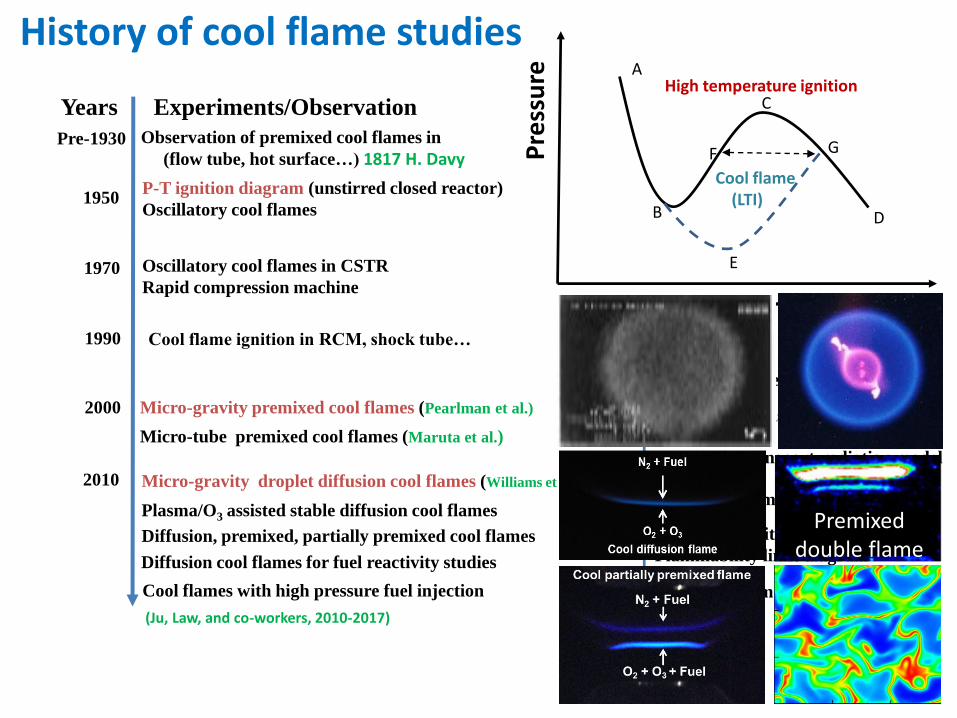
1970
Detailed kinetic mechanism
2000
2010
1950
1D Kinetic-transport-radiation model
Thermo-kinetic models
R+ O2 = RO2 mechanism
Unified chain-reaction theory
1990
Pre-1930 Observation of premixed cool flames in
(flow tube, hot surface…) 1817 H. Davy
P-T ignition diagram (unstirred closed reactor)
Oscillatory cool flames
Cool flame chemistry
CH2O formation
0D kinetic modeling
2D turbulent modeling
1D knocking model
1D kinetic-Transport model
Extinction limits
Flammability limit diagram
Cool flames with high pressure fuel injection
Micro-gravity premixed cool flames (Pearlman et al.)
Micro-gravity droplet diffusion cool flames (Williams et al.)
Plasma/O3 assisted stable diffusion cool flames
Diffusion, premixed, partially premixed cool flames
Diffusion cool flames for fuel reactivity studies
Micro-tube premixed cool flames (Maruta et al.)
Oscillatory cool flames in CSTR
Rapid compression machine
Years Experiments/Observation Kinetics-theory-models
Cool flame ignition in RCM, shock tube…
Pre
ssu
re
Temperature
E
Cool flame(LTI)
High temperature ignitionA
B
C
D
F G
History of cool flame studies
(Ju, Law, and co-workers, 2010-2017)
Premixed double flame

6
A puzzle on cool flame propagation at elevated temperature
Y. Ju et al., Proc. of Combust. Inst., 33, 2011
0.1 1
1000
1500
2000
2500
Te
mp
era
ture
dis
trib
utio
n (
K)
Flame radius, r (cm)
0.1ms
3.0ms
9.3ms
n-heptane
p=20atm, T=700K
Cool flame
Spark ignition
Spark assisted HCCI flame propagation:(High pressure, elevated temperature)
hot flame
Q
• Why is there a double flame structure with coupled hot/cool flames?
• How fast and how can a cool flame can propagate?
• What is the effect of pressure on cool flame burning limit?
Hot flame by a spark1 atm, 300 K
1. Dynamics and Regimes of Premixed Cool Flames
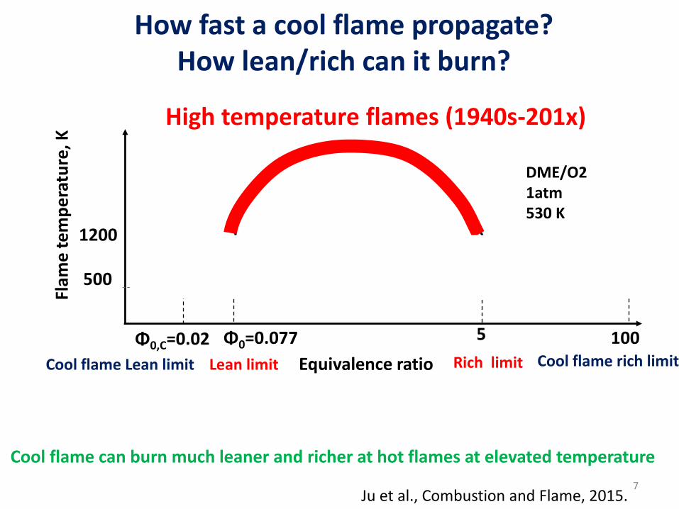
How fast a cool flame propagate?How lean/rich can it burn?
High temperature flames (1940s-201x)
w. cool flame
Flam
e t
em
pe
ratu
re, K
Equivalence ratio
Φ0,C=0.02 Φ0=0.077
Cool flameCool flame
1200
500
5 100
Ju et al., Combustion and Flame, 2015.
Lean limit Rich limit
7
DME/O2 1atm530 K
Cool flame Lean limit Cool flame rich limit
Cool flame can burn much leaner and richer at hot flames at elevated temperature

How does pressure affect flame regimes and structure?
8
0 2 4 6 8 10
500
1000
1500
2000
2500
E
Cool flame
Double flame
Cool flame
Hot flame
F
D
C
B
A
1.5atm 1atm
4atm
2atm
P=20atm
DME/air
Fla
me
tem
pera
ture
(K
)
Equivalence ratio
• Pressure dramatically changes flammable region of lean cool flames, but not the rich cool flame
• The cool flame to hot flame transition limit is sensitive to pressure.
Y. Ju, Combustion and Flame, 2017
1. Why do we have three different flame regimes on lean side?
2. What is the cool flame structure on the rich side?
3. Do we still have a cool flame at high pressure?
3 Questions?

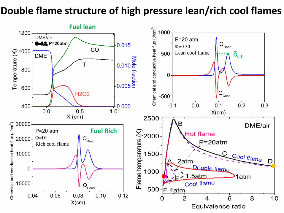
Different flame structures (2 atm)
-0.25 0.00 0.25500
1000
1500
2000
2500
3000
X (cm)
Tem
pe
ratu
re (
K)
1E-3
0.01
0.1Normal
flame
T
H2OCO2DME
CO
T CH
2O
Mole
fractio
n
DME/O2
=0.1
-0.5 0.0 0.5 1.0 1.5
400
600
800
1000
1200
1400
1600
X (cm)
Tem
pe
ratu
re (
K)
1E-3
0.01
0.1Double
flame
T
H2O
CO2
DME
CO
T
CH2O
Mole
fractio
n
DME/O2
=0.1
-0.5 0.0 0.5 1.0 1.5
400
600
800
1000
1200
1400
1600
X (cm)
Tem
pe
ratu
re (
K)
1E-5
1E-4
1E-3
0.01
0.1Cool flame
H2O2
HCOOH
HO2
CH4T
T
Mole
fractio
n
DME/O2
=0.1
0.00 0.05 0.10 0.15 0.20 0.25 0.30
1000
1500
2000
dc
b
a
300 K
T0=530 K
DME/O2
Fla
me
tem
pera
ture
, K
Equivalence ratio
Normal
flame
Cool flame
CH2O
Flame size=1.5cm
Hot flame
Cool flameDouble
flame
0.0 0.5 1.0400
600
800
1000
1200DME/air
P=20atm
CODME
T
X (cm)
Te
mp
era
ture
(K
)
H2O2
0.000
0.005
0.010
0.015
Mo
le fra
ctio
n
Double flame structure of high pressure lean/rich cool flames
-0.1 0.0 0.1 0.2 0.3
-500
0
500
1000
QCond
QReac
P=20 atm
Lean cool flame
Ch
em
ica
l a
nd
co
nd
uctive
he
at
flu
x (
J/c
m3)
X(cm)
0.04 0.06 0.08 0.10 0.12
-10000
0
10000
20000
30000
QCond
QReac
P=20 atm
Rich cool flame
Ch
em
ica
l a
nd
co
nd
uctive
he
at
flu
x (
J/c
m3)
X(cm)
δc,h
0 2 4 6 8 10
500
1000
1500
2000
2500
E
Cool flame
Double flame
Cool flame
Hot flame
F
D
C
B
A
1.5atm 1atm
4atm
2atm
P=20atm
DME/air
Fla
me
tem
per
atu
re (
K)
Equivalence ratio
Fuel lean
Fuel Rich

Effects of pressure and mixture dilution on cool flame speeds and burning limits
5 10 15 200.0
0.5
1.0
Cool flame,
Hot flame, SL
Normalized pressure, P/1atm
No
rmalz
ied fla
me tem
pe
ratu
re, T
f
Tf
Cool flame,
0.5
1.0
1.5
No
rma
lize
d fla
me s
pe
ed
, SL
• Lean and rich cool flame speed and temperature have distinctive pressure dependence due to the NTC effects.
0.1 1 10
10
100
DME/(0.1O2+0.9N2)
DME/air
F
A EDC
B Cool flame
Hot fla
me
Cool flame
P=2atm
(b)
Fla
me
sp
ee
d (
cm
/s)
Equivalence ratio
• Dilution and EGR enhance cool flames and suppress hot flames
Y. Ju, Combustion and Flame, 2017
12
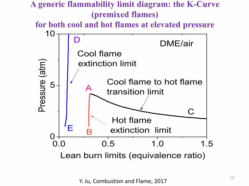
0.0 0.5 1.0 1.50
5
10D
C
E B
A
Hot flame
extinction limit
Cool flame to hot flame
transition limit
Cool flame
extinction limit
DME/air
Pre
ssu
re (
atm
)
Lean burn limits (equivalence ratio)
A generic flammability limit diagram: the K-Curve
(premixed flames)
for both cool and hot flames at elevated pressure
Y. Ju, Combustion and Flame, 2017
13
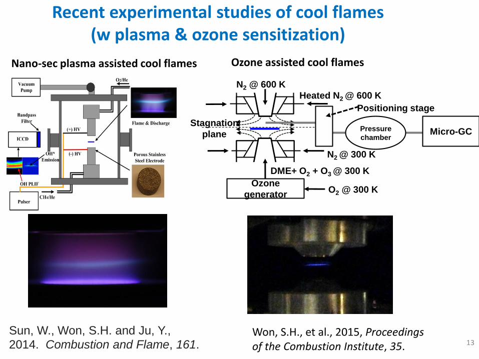
Recent experimental studies of cool flames(w plasma & ozone sensitization)
Heated N2 @ 600 K
N2 @ 300 K
Stagnation
plane
DME+ O2 + O3 @ 300 K
N2 @ 600 K
Pressure
chamberMicro-GC
Positioning stage
Ozone
generatorO2 @ 300 K
Sun, W., Won, S.H. and Ju, Y.,
2014. Combustion and Flame, 161.Won, S.H., et al., 2015, Proceedings of the Combustion Institute, 35.
Nano-sec plasma assisted cool flames Ozone assisted cool flames

Hot Flame to Cool Flame Transition: 3 flame regimes
14
Premixed Flame Extinction transition
from hot flame to cool flame
• Constant strain rates
• Reducing fuel concentration
Hot flame
Hot flameCool flame
Coolflame
0.1 1
1000
1500
2000
2500
Tem
pera
ture
dis
trib
ution
(K
)
Flame radius, r (cm)
0.1ms
3.0ms
9.3ms
n-heptane
p=20atm, T=700K
Cool flame formation
Spark ignition
Spark assisted HCCI combustion
0
2
4
6
8
10
12
14
16
10 15 20 25 30
Ma
xim
um
Fla
me
In
ten
sit
y (
a. u
.)
Time (s)
Hot
Flame
Cool
Flame
ϕ = 0.102 ϕ ~ 0.090
Reuter, C.B., Won, S.H. and Ju, Y., 2016. Combustion and Flame, 166, pp.125-132.

400
800
1200
1600
2000
2400
0.1 1 10 100 1000 10000
Maxim
um
tem
pera
ture
Tm
ax [
K]
Strain rate a [1/s]
nC7H16/N2 vs O2 or O2/O3
in counterflow burner
Xf = 0.05,Tf = 550 K, and To = 300 K
Extinction limit of
conventional hot diffusion flame
(HFE)
Extinction limit of
cool diffusion flame
(CFE)
without O3
with O3
HF branch
CF branchHTI
LTI
2. Dynamics of Diffusional Cool Flames
• Existence of cool diffusion flames in counterflowconfiguration with n-heptane– cool flame regime exists regardless of addition of ozone– Addition of ozone extends cool flame regime.
16
(b) Hot diffusion flame
(a) Cool diffusion flame
Won, S.H., et al., 2015, Proceedings of the Combustion Institute, 35.

Self-Sustaining partially premixed Cool
Flames
• Cool partially premixed flames: DME/O2/O3
17Reuter et al., Proc. Combust. Inst. 2017
(a)
Hot partially premixed flame
Transition from cool flames to hot flames• Start w/ partially premixed cool flame at a = 73 s-1,
ϕ = 0.11, XF = 0.44
• Gradually add fuel to diffusion side up to XF ~ 0.48
• At a higher fuel concentration cool flame transfer to hot flames
18
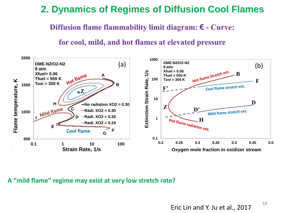
500
1000
1500
2000
0.1 1 10 100
Fla
me t
em
pera
ture
, K
Strain Rate, 1/s
DME-N2/O2-N28 atmXfuel= 0.06Tfuel = 550 KToxi = 300 K
No radiation XO2 = 0.30
Radi. XO2 = 0.30
Radi. XO2 = 0.26
Radi. XO2 = 0.24
A
F
B
C
E
D
G
H
I
Cool flame
Z
(a)
0.1
1
10
100
1000
0.2 0.25 0.3 0.35 0.4 0.45 0.5E
xti
ncti
on
Str
ain
Rate
, 1/s
Oxygen mole fraction in oxidizer stream
DME-N2/O2-N28 atmXfuel = 0.06Tfuel = 550 KToxi = 300 K
B
H
ZD
F
D’
F’
(b)
Diffusion flame flammability limit diagram: € - Curve:
for cool, mild, and hot flames at elevated pressure
A “mild flame” regime may exist at very low stretch rate?
Eric Lin and Y. Ju et al., 2017
2. Dynamics of Regimes of Diffusion Cool Flames

n-C7H16-30-70% O2-He, 1atm
Droplet ISS
a. Droplet extinction: diffusion vs. radiation(Flex experiment)
Relationship
Small D0
Large D0
Model cross-validation
Counterflow Cool flame
Fuel
O2/He
Stretch rate, s-1
Flam
e t
em
per
atu
reCool flame
Hot flame
Cool flame
Stretch Extinction (SE)
Radiation Extinction (RE)
aH,SE
aC,SE
aC,RE
aH,RE
Lower YO2
0
b. Counterflow l flame extinction: stretch vs. radiationTop: Experiment cool flame, Bottom: Schematic
Cool flame
Hot flame
Competition between radiation/diffusion heat loss with chemical heat release

20
Effect of air temperature on diffusion cool flame burning limits
400
900
1400
1900
2400
0.1 1 10 100 1000 10000
Fla
me T
em
pera
ture
(K
)
Strain Rate (1/s)
DME/N2 vs Airp = 8 atmXF = 0.10TFuel = 550 K
TO = 900 K
500 K300 K
300 K
The increase of air temperature dramatically affects the cool flame regimes and burning limits:
• Cool flame shifts to higher stretch rate• mild flame branch disappear on high stretch side.• Radiation extinction limit disappear on low stretch side.
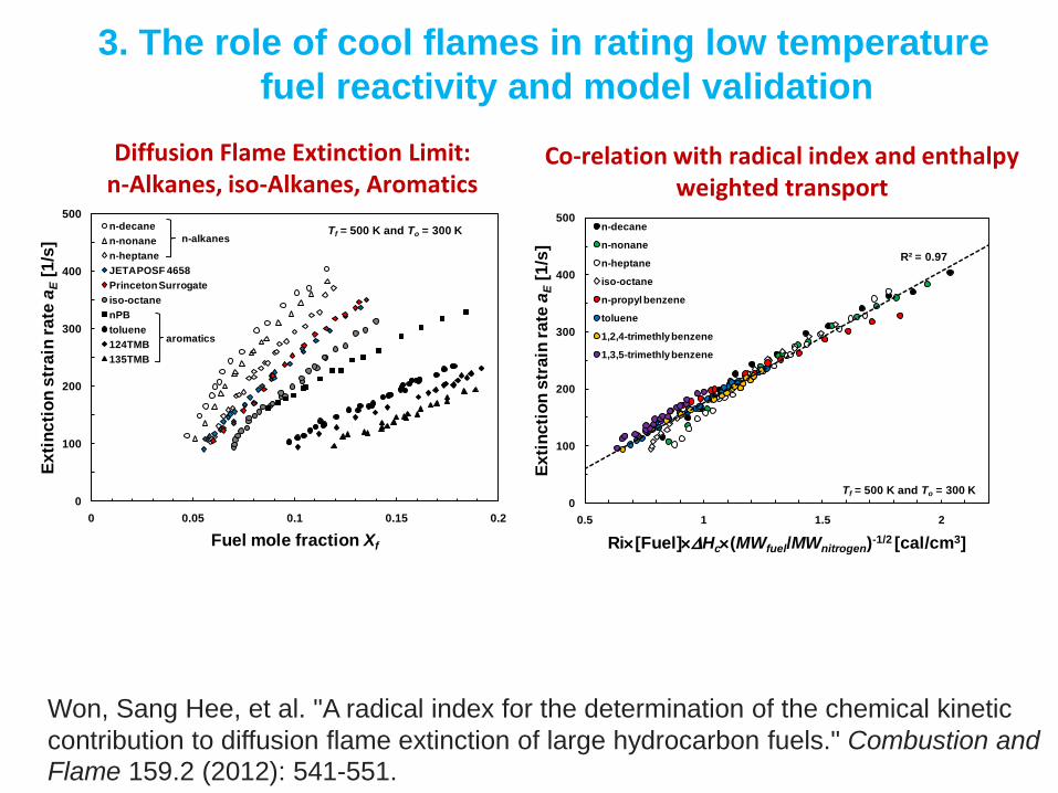
3. The role of cool flames in rating low temperature
fuel reactivity and model validation
0
100
200
300
400
500
0 0.05 0.1 0.15 0.2
Ex
tin
cti
on
str
ain
ra
te a
E[1
/s]
Fuel mole fraction Xf
n-decane
n-nonane
n-heptane
JETA POSF 4658
Princeton Surrogate
iso-octane
nPB
toluene
124TMB
135TMB
n-alkanes
aromatics
Tf = 500 K and To = 300 K
R² = 0.97
0
100
200
300
400
500
0.5 1 1.5 2
Ex
tin
cti
on
str
ain
ra
te a
E[1
/s]
Ri[Fuel]Hc(MWfuel/MWnitrogen)-1/2 [cal/cm3]
n-decane
n-nonane
n-heptane
iso-octane
n-propyl benzene
toluene
1,2,4-trimethly benzene
1,3,5-trimethly benzene
Tf = 500 K and To = 300 K
Diffusion Flame Extinction Limit: n-Alkanes, iso-Alkanes, Aromatics
Co-relation with radical index and enthalpy weighted transport
Won, Sang Hee, et al. "A radical index for the determination of the chemical kinetic
contribution to diffusion flame extinction of large hydrocarbon fuels." Combustion and
Flame 159.2 (2012): 541-551.

30
50
70
90
110
130
150
170
0.01 0.10 1.00
Ex
tin
cti
on
Str
ain
Ra
te (
s-1
)
Fuel Mass Fraction, YF
nC7
Flames0% O3
Exp HFE Exp CFENUI-S131 HFE NUI-S131 CFENUI-S238 HFE NUI-S238 CFENUI-S526 HFE NUI-S526 CFENUI-Full CFE
-5.0E-5
0.0E+0
5.0E-5
1.0E-4
1.5E-4
2.0E-4
2.5E-4
3.0E-4
3.5E-4
C0 C1 C2 C3 C4 C5 C6 C7 C8Heat
rele
ase
ra
te (
kca
l/c
m2-s
)
Reaction Size
nC7 Cool FlameYF = 0.284a = 38 s-1
O3 = 0%
S131-CF
S238-CF
S526-CF
Full-CF
Will a model, which captures low temperature ignition well, be able to predict extinction limits of cool flames?
• The answer is no! we need to capture the low temperature heat release rate correctly.
• Cool flames can play an important role in model validation for heat release rate.
Reuter, C.B., Lee, M., Won, S.H. and Ju, Y., 2017. Combustion and Flame, 179, pp.23-32.
30
50
70
90
110
130
150
170
0.01 0.10 1.00
Ex
tin
cti
on
Str
ain
Ra
te (
s-1
)
Fuel Mass Fraction, YF
Fuel/N2 vs O2
Cool Flames0% O3
nC12 (Exp) nC10 (Exp) nC8 (Exp) nC7 (Exp)
nC12-S145 nC10-S149 nC8-S133 nC7-S141

PRINCETONMechanical and Aerospace Engineering
• Laminar Flame Speed
• Flame Extinction
Cool Flames as Mechanism
Validation Experiments
23
Hig
h T
em
p
Full-Strength
(Heat release rates)
Low
Tem
p
Laminar
Flame
Speed
?
S L
φ
a Ext
XF
Flame
Extinction
Diluted
(Kinetics)
Validation in systems with chemistry-transport-heat release coupling:
No validation of heat release rate at low temperatures!
“Experimental blind spot” – can be addressed in cool flame measurements
• Shock tube• RCM• JSRT• µ tube
Cool flames
24
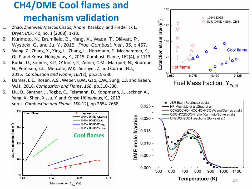
0.050 0.075 0.100 0.12550
75
100
125
150
Cool flame
Exti
ncti
on
str
ain
rate
(s
-1)
100% DME
50% DME + 50% CH4
Hot flame
Fuel Mass fraction, YFuel
CH4/DME Cool flames and mechanism validation
Cool flames
500 600 700 800 900 1000 11000.000
0.005
0.010
0.015
0.020
0.025 JSR Exp. (Rodriguez et al.)
HP-Mech/Liu et al./Zhao et al.
OCH2OCHO=HOCHO+HCO (Wang/Dames et al.)
QOOH/O2QOOH ratio (Kurimoto/Burke et al.)
CH2OCH2O2H reactions (Burke et al.)
DM
E m
ole
fra
cti
on
Temperature (K)
1. Zhao, Zhenwei, Marcos Chaos, Andrei Kazakov, and Frederick L. Dryer, IJCK, 40, no. 1 (2008): 1-18.
2. Kurimoto, N., Brumfield, B., Yang, X., Wada, T., Diévart, P.,
Wysocki, G. and Ju, Y., 2015. Proc. Combust. Inst., 35, p.457.3. Wang, Z., Zhang, X., Xing, L., Zhang, L., Herrmann, F., Moshammer, K.,
Qi, F. and Kohse-Höinghaus, K., 2015. Combust. Flame, 162(4), p.1113.4. Burke, U., Somers, K.P., O’Toole, P., Zinner, C.M., Marquet, N., Bourque,
G., Petersen, E.L., Metcalfe, W.K., Serinyel, Z. and Curran, H.J., 2015. Combustion and Flame, 162(2), pp.315-330.
5. Dames, E.E., Rosen, A.S., Weber, B.W., Gao, C.W., Sung, C.J. and Green, W.H., 2016. Combustion and Flame, 168, pp.310-330.
6. Liu, D., Santner, J., Togbé, C., Felsmann, D., Koppmann, J., Lackner, A., Yang, X., Shen, X., Ju, Y. and Kohse-Höinghaus, K., 2013. sures. Combustion and Flame, 160(12), pp.2654-2668.
Conclusion
•Cool flames lead to many new flame regimes, dynamics, and insights in combustion research and engine development.
•Cool flames extend the burning limits and add new physics and time/length scales in combustion dynamics.
•Cool Flames provide a new platform in validation of low temperature chemistry.
•Experiments of high pressure/turbulent cool flames, and ignition assisted cool flames are interesting and challenging.
25

26