dynamics of two active autonomous dock … of two active autonomous dock mechanisms for auv recovery...
TRANSCRIPT

DYNAMICS OF TWO ACTIVE AUTONOMOUS DOCK MECHANISMS FOR AUV RECOVERY
Jason Currie1, Colin B. Gillis1, Juan A. Carretero1, Rickey Dubay1, Tiger Jeans1 and George D. Watt21Department of Mechanical Engineering, University of New Brunswick, Fredericton, NB, Canada
2Defence Research and Development Canada, Halifax, NS, CanadaE-mail: [email protected]; [email protected]; [email protected]
© 2013 Defence Research and Development Canada
Received November 2013, Accepted March 2014No. 13-CSME-189, E.I.C. Accession 3647
ABSTRACTAutonomous Underwater Vehicles (AUVs) are presenting an ever expanding range of applications that en-hance human capabilities and mitigate human risk. Development of a successful subsurface autonomouslaunch and recovery system would expand the functional use of AUVs in many fields, e.g., year-roundCanadian Arctic exploration and sovereignty missions. This paper provides an overview of the design anddynamic modelling of two concept mechanisms being developed to recover AUVs to a slowly moving sub-merged submarine. Both have a serial R⊥R⊥P architecture; one is mechanically actuated while the seconduses an actively pitched wing to indirectly provide motive force for the passive revolute joint. Dynamic mod-els of both manipulators are developed. Although similar in architecture, several extensions are required toaccurately predict the non-linear dynamics provided by the wing. High speed actuation of the devices isrequired to compensate for relative trajectory errors between the submarine and AUV during significant seastates in littoral waters. Alterations to the recursive Newton–Euler method to include hydrodynamic andadditional inertial forces present in water are explained. Results of some initial modelling are presented.
Keywords: AUV; serial manipulator; passive joint; manipulator dynamics; hydrodynamics.
DYNAMIQUE DE DEUX SYSTÈMES AUTONOMES DE RÉCUPÉRATION D’AUV
RÉSUMÉLes véhicules sous-marins autonomes (AUV) présentent un éventail toujours croissant d’applications quiaméliorent les capacités humaines et aident à atténuer les risques pour les humains. Le développement d’unsystème autonome pour mettre à l’eau et récupérer les AUVs permettrait d’étendre l’utilisation fonctionnellede ces véhicules dans des nombreux domaines, e.g., l’exploration de l’Arctique canadien et les missionsde souveraineté pendant toute l’année. Ce document donne un aperçu de la modélisation dynamique et laconception de deux systèmes qui permettront de récupérer les AUVs à un sous-marin. Les deux sont des ma-nipulateurs en série R⊥R⊥P, le premier est actionné mécaniquement tandis que le deuxième utilise une ailedont l’angle d’attaque est actionné pour fournir indirectement une force motrice. Les modèles dynamiquesdes deux manipulateurs sont développés. Bien que similaires en architecture, plusieurs extensions sont né-cessaires pour prédire avec précision la dynamique non-linéaire produite par l’aile. L’actionnement à grandevitesse des appareils est nécessaire pour compenser les erreurs de trajectoire entre le sous-marin et l’AUVpendant les états de mer significatives dans les eaux littorales. Les modifications apportées à la méthode ré-cursive de Newton–Euler pour inclure les forces hydrodynamiques et autres forces d’inertie présentes dansl’eau sont expliquées. Les résultats d’une modélisation initiale sont aussi présentés.
Mots-clés : AUV; manipulateur en série; joint passive; dynamique de manipulateurs; hydrodynamique.
Transactions of the Canadian Society for Mechanical Engineering, Vol. 38, No. 2, 2014 213

Fig. 1. Generic illustration of the proposed docking scenario.
1. INTRODUCTION
Autonomous Underwater Vehicles (AUVs) are presenting an ever expanding range of applications that en-hance human capabilities and mitigate human risk. The main limitation of these vehicles is endurance.Oceanographers and scientists envision continuous automated surveying of geology and marine life. Naviesand governments desire continual surveillance of territory, and autonomous front line capabilities deliveredcovertly by submarines [1]. The bottleneck in the adoption of these capabilities is a viable autonomousLaunch and Recovery (L&R) system [2].
Watt et al. [3] discuss three kinds if AUV L&R systems: passive subsurface stationary docks, surfaceships, and torpedo tube L&R for military submarines. The majority of existing AUV docking devicesuse some form of man-in-the-loop control with the exception of autonomous subsurface stationary docks.Present autonomous AUV docking experiments have yielded marginal success rates, primarily due to limitedlateral dexterity of streamlined AUVs. Active control of the dock appears to be necessary for higher successrates.
Defence Research and Development Canada (DRDC) has proposed an innovative project to develop anactive automated docking device to be used on slowly moving submarines while maintaining level flightwith various AUV designs. Figure 1 illustrates the proposed scenario of recovering an AUV to a submergedsubmarine. A generic representation of the active docking mechanism is shown. The University of NewBrunswick (UNB) is assisting in this multi-year project with the design and development of specific ac-tive dock mechanisms along with their dynamic models and motion controllers for multi-body simulations.This paper discusses the formulation of a dynamic model for both a mechanically actuated and a partiallyhydrodynamically actuated docking device for which physical prototypes are being built.
1.1. Related ResearchThe development of AUVs and AUV supporting systems is ongoing and has been gaining significance forover a decade. The United States of America’s Department of the Navy has compiled an AUV masterplan [1], outlining the goals and strategic advantage of implementing and using an AUV program. Theplan depicts the use of AUV fleets with a centralized mission control ship, discussing the importance ofAUV support systems and infrastructure. The development of an active autonomous L&R docking device isrequired to progress the functionality of using AUVs.
The current autonomous docking devices have had marginal success rates, too low to merit the risk ofusing the AUVs in service. Stokey et al. [4] achieved a 62% docking rate using a REMUS 100 AUV anda 1 m diameter stationary funnel dock with acoustic homing. Allen et al. [5] obtained a similar dockingrate of 60% using an updated version of a similar setup with a rectangular funnel dock. Both trials used
214 Transactions of the Canadian Society for Mechanical Engineering, Vol. 38, No. 2, 2014

varying locations and environmental conditions, and were conducted in conjunction with the Woods HoleOceanographic Institution. Using electromagnetic homing, Feezor et al. [6] achieved successful docking infive out of eight attempts. They used a SeaGrant Odyssey IIB AUV and a 1 m diameter stationary funneldock. The trials were preformed over a two week period in environmental conditions with cross currentsupwards of 0.3 m/s. They noted that docking typically failed when the AUV was initially misaligned withthe dock by more than 30 degrees. Additional similar stationary docking trials have been performed withvarious homing and sensing schemes [7–9] but without presenting docking success rates. Surface shipstypically use human-controlled L&R systems involving cranes or ramp systems [10, 11]. There are surfaceL&R systems under development using towed bodies [12], and some are even using Unmanned SurfaceVehicles (USVs) to autonomously recover AUVs [13]. Successful recovery of an AUV by any surfacesystem is highly dependent on the sea state [3].
Many countries are interested in an AUV L&R capability for submarines [2, 14–16]. Fedor [14] dis-cusses optimal AUV docking locations along a submarine. To maximize docking feasibility, Fedor suggestsdocking occurs in areas with minimal disturbances, e.g., avoiding local turbulence from obstructions suchas the submarine sail. The current submarine docking systems under development utilize either tetheredRemotely Operated Vehicles (ROVs) [2, 15, 16] or a deployed stationary dock [17] for AUV recovery. Thecurrent methods also recover to the submarine’s torpedo or missile tubes, disabling their traditional use forthe submarine.
The majority of these docking devices rely on either the AUV for correctly aligning itself with the dockor man-in-the-loop remote control. As described by the Director of Innovation, of the US Office of NavalResearch, AUV recovery must account for the: sea state, operational tempo, autonomy, motion prediction,and AUV maneuvering and control authority to be successful and robust [2]. Seizer [12] notes the absenceof ship board autonomous AUV L&R devices. DRDC suggests that the deficiencies apparent with stationaryautonomous docking systems might be corrected using active autonomous docking.
A successful active, autonomous AUV docking device will require a mechanism with the control anddexterity to achieve contact with the AUV in the presence of environmental disturbances. Mechanicallyactuated manipulators are currently in use with submerged ROVs [18]. These are typically used for precisiontasks but on a relatively small size scale. Control of ship board robotic manipulators has been explored byFrom et al. [19]. They augment a Proportional-Derivative (PD) controller with a real-time wave predictionmodel to overcome the non-inertial effects of the manipulator base and optimize joint torques for prescribedtrajectories.
There has been significant effort to develop AUV docking systems, all with marginal success rates. Thefunctional use of AUVs is limited by the absence of a robust AUV docking device. An active, autonomous,reliable AUV docking device would allow AUVs to be recovered to naval platforms quickly. The success-ful implementation of such a device will require the synthesis of sensing information, robust autonomouscontrol, and an actuated mechanism with sufficient dexterity to overcome relative motion between the AUVand submarine imposed by environmental disturbances. This project will contribute to the development ofAUV docking by proposing an active autonomous AUV docking solution for submarines.
1.2. Project ScopeThe AUV underwater docking problem is complex. DRDC states the docking solution should providefor [3]:
• deep water operations,
• littoral operations with minimal sea state limitations,
• automation for reliability and temporal efficiency,
Transactions of the Canadian Society for Mechanical Engineering, Vol. 38, No. 2, 2014 215

• low risk to the submarine propeller or appendages should something break or let go during docking,
• low risk of AUV/submarine collision in the presence of environmental disturbance,
• a flexible choice of AUV size and shape to maximize endurance and functionality,
• minimal docking infrastructure on the AUV to simplify use off-the-shelf commercial vehicles.
More specifically, it is convenient to consider docking in three primary stages: making physical contactbetween the AUV and dock, capture, and parking [3]. Achieving precise contact with the AUV has beenidentified as the most challenging task of this project, largely because the system has complex nonlineardynamics and if unsuccessful capture will become infeasible. Thus, designing a dock prototype which iscapable of achieving precise contact with the AUV has been established as the first stage of the overallproject. UNB will provide a proof-of-concept design, including a dynamic model of the prototype and itscontroller for initial multi-body simulations. DRDC and other collaborators will provide sensing systems,AUV homing trajectories, and expertise to assist in the development of the initial prototype design fordynamic simulation. AUV capture will occur alongside the submarine, heading into the waves, while thesubmarine is at depth maintaining level flight in littoral waters. All designs must be made fail safe inoperation to mitigate the risk to submariners. The most important of the UNB design objectives are:
• the primary objective of the dock mechanism is to provide transverse trajectory corrections for theAUV during the final stages of achieving contact,
• the submarine will maintain straight and level flight at 2 to 3 knots (≈ 1.5 m/s),
• docking will occur from 4 to 8 m off the side of the submarine’s hull, at the midline of the submarinewhere the flow is most uniform,
• the dock must achieve precise contact with a point on the AUV; given a tolerance of ±0.005 m,
• initially, the orientation of the AUV will be neglected, reducing the task to three Degrees Of Freedom(DOF) and focusing on accurately contacting a point on the AUV,
• the worst case scenario is defined as docking at 15 m depth in littoral waters in sea state 6 (4 to 6 mhigh waves),
• the worst case AUV motion is assumed to be the fluid particle motion given by unimodal linear wavetheory predictions of sea state 6 waves, and
• the dock design must be fail-safe, minimizing risk to submariners.
2. CONCEPTS
A large number of actuation concepts were analysed for the docking mechanism. They can be classified aseither hydrodynamically or mechanically actuated. Hydrodynamically actuated designs included directedwater-jets, ducted fans, and actively controlled hydrofoils on links of arms or towed bodies. Mechanicallyactuated designs contained more traditional power transformers such as scissor arm linkages, and motoractuated links. Less conventional concepts such as tensioned spring and cable articulated bodies, and ad-justable arrestor cables were also investigated [20, 21].
Concept winnowing was a large task accounting for input from a wide variety of sources. Fail-safedesign considerations, consultations with submariners, and proof-of-concept analysis were the main driversof the process. These inputs lead to the avoidance of mechanisms using cables or towed bodies due to the
216 Transactions of the Canadian Society for Mechanical Engineering, Vol. 38, No. 2, 2014

(a) (b)
Fig. 2. The two autonomous dock concepts under development, shown with their faired base (submarine absent).(a) Mechanically actuated 3-DOF arm and (b) hydrodynamically actuated wing.
increased risk of fouling the propeller. Eventually the two most promising concept designs were agreedto be a mechanically actuated R⊥R⊥P serial manipulator (or RRP for short), shown in Fig. 2(a), and ahydrodynamically actuated R⊥ R⊥P serial manipulator (or wing dock), as shown in Fig. 2(b). The R⊥ R⊥Parchitecture uses the forward motion imparted by the submarine and an actively pitched wing to indirectlyprovide motive force for the passive revolute joint, denoted by R.
The RRP robotic arm, using a 2-DOF shoulder joint at the submarine hull, will be able to move in thehorizontal (x-y) plane in addition to the transverse (x-z) plane. Having each joint actively driven with amotor leads to the potential benefits of: rapid closed-loop response times, a relatively simple and robustcontrol algorithm, good disturbance rejection characteristics, and the fact that actuation does not requirefluid flow. The hydrodynamically actuated concept will derive potential benefits of: low actuation powerand noise, inherent streamlining for reduced drag, and passive compliance to compensate for submarine roll.
3. MODEL DEVELOPMENT
A benchmark end effector trajectory is first established based on the docking parameters. Standard manipu-lator kinematic and dynamic models are employed as much as possible. Kinematic similarities between thetwo manipulators leads to nearly identical models; since the wing is effectively a non-linear replacement fora motor it simply becomes an extension to the RRP solution rather than a completely divergent derivation.
Section 3.3 describes the general alterations required for both manipulators to account for hydrodynamiceffects. Further alterations to analyse motive power provided by the wing are discussed in Section 3.4. Thechosen control scheme is introduced in Section 4. Results of initial simulations for both manipulators arepresented in Section 5.
3.1. Establishing the End Effector Design TrajectoryThe kinematics of the end effector must be able to match the relative motion between the submarine andAUV. the worst case design point is taken to be the kinematics of a fluid particle at a depth of 15 m withinsea state 6 waves in littoral waters, a conservative approach that assumes the large submarine is unaffectedby the waves and the small AUV moves with the local fluid. Fluid particle kinematics are calculated usingunimodal linear wave theory [22]. Figure 3 shows that this relative motion between the submarine and theAUV can be significant. Maximum displacements can exceed ± 4 m within a 17 s wave period, while boththe velocity and acceleration also have large amplitudes.
Transactions of the Canadian Society for Mechanical Engineering, Vol. 38, No. 2, 2014 217

0 2 4 6 8 10 12−5
0
5
Pos
ition
[m]
x (Tmin)
z (Tmin)
0 2 4 6 8 10 12 14−5
0
5
Pos
ition
[m]
x (Tavg)
z (Tavg)
0 5 10 15 20−5
0
5P
ositi
on [m
]
Time [sec]
x (Tmax)
z (Tmax)
Fig. 3. Relative horizontal (x-axis) and vertical (z-axis) wave particle displacements as a function of time for sea state6, with a wave height of 6 m and at depth of 15 m, given a minimum wave period (Tmin) of 10.5 s (top), an averagewave period (Tavg) of 13.8 s (middle), and a maximum wave period (Tmax) of 17.5 s (bottom).
3.2. KinematicsConventional joint frames are assigned to each link of both mechanisms, as shown in Fig. 2, using theDenavit–Hartenberg notation described in Craig [23]. The forward displacement problem, x, is a Cartesianposition vector which describes the position components of the end effector of the manipulator as seen fromits base as a function of the specific position of each joint. Vector x is solved using the propagation ofhomogeneous transformation matrices and is given by
x=
cos(θ1)sin(θ2)d3
sin(θ1)sin(θ2)d3
−cos(θ2)d3
(1)
where θ1 and θ2 are the joint angles associated with joints 1 and 2, respectively, and d3 is the joint offsetassociated with joint 3. Conversely, the inverse displacement solution uses a geometric solution to solvethe joint angles/offset (2 = [θ1,θ2,d3]T ) given a Cartesian end effector position x. The quadrant correctedarctangent function (i.e., the atan2 function) is applied to solve a specific joint angle θi , given the vectorcomponents of link i as seen from the base frame of the manipulator. 2 is described as
2=
atan2(y,x)atan2(z,
√y2+x2)+ π
2√x2+y2+ z2
(2)
The forward velocity solution is obtained through solving the time derivative of the forward displacementproblem; it is convenient to write the forward velocity solution in the form of a matrix equation:
x= J(2)2 (3)
where x is a vector of Cartesian velocities of the end effector, 2 is a vector of joint velocities, and J is theJacobian matrix of the manipulator. The Jacobian matrix is defined as the matrix that transforms the joint
218 Transactions of the Canadian Society for Mechanical Engineering, Vol. 38, No. 2, 2014

(a) (b)
Fig. 4. (a) Cartesian kinematics of end effector and (b) joint kinematics of RRP mechanically actuated active dock, allfor an average wave period of 13.8 s.
rates in actuator space to the velocity state in the end effector space, and can be described as
J(2)=
−sin(θ1)sin(θ2)d3 cos(θ1)cos(θ2)d3 cos(θ1)sin(θ2)
cos(θ1)sin(θ2)d3 sin(θ1)cos(θ2)d3 sin(θ1)sin(θ2)
0 sin(θ2)d3 −cos(θ2)
(4)
Equation (3), is manipulated using basic matrix operations to solve the inverse velocity solution, 2,
2= J−1(2)x (5)
Similarly, the forward and inverse acceleration solutions are derived by taking the time derivative of theforward and inverse velocity solution matrix equation respectively,
x= J(2)2+J(2)2 (6)
2= J−1(2)x+J−1(2)x (7)
where x is a vector of Cartesian accelerations, 2 is a vector of joint accelerations, and J is the time derivativeof the Jacobian matrix of the manipulator.
The serial manipulator kinematics can now be fully defined; allowing the motion of the mechanism to bedescribed in both Cartesian space and joint space. The resultant kinematics required to meet the establishedaverage wave period design trajectory, as shown in Fig. 3, for the RRP mechanically actuated active dockare shown in Fig. 4. The kinematics for the wing dock differ slightly. Kinematically, joint 1 in the wingdock is used for deployment only, it is fixed during the docking procedure. In regards to the specified task oftracking the AUV path error in the transverse plane, the wing dock is a 2-DOF manipulator. Rotation aboutthe shoulder (θ2), and radial extension of the end effector (d3) fully define the position of the end effectorin the transverse plane. Therefore, the required kinematics of the wing dock given an average wave periodare shown in Fig. 5. The kinematics of the wing itself, as it provides the motive force for θ2, is incorporatedinto the dynamic model of the wing which is discussed later.
Transactions of the Canadian Society for Mechanical Engineering, Vol. 38, No. 2, 2014 219

(a) (b)
Fig. 5. (a) Cartesian kinematics of end effector and (b) joint kinematics of RRP hydrodynamically actuated activedock, all for an average wave period of 13.8 s.
3.3. DynamicsAt this point the mechanism links are assumed to be rigid bodies. The development of the equations ofmotion (EOM) will be completed with the recursive Newton–Euler formulation as opposed to the singlebody approach common to hydrodynamic analysis. The recursive technique maintains the advantage ofhaving constant moment of inertia tensors for each link. It also provides flexibility for the project to addfurther DOF to the end effector without re-completing the dynamic analysis of the entire manipulator. ExtraDOF could be required to account for orientation between the AUV and end effector.
Inward iterations are performed to propagate accelerations from the end effector to Joint 1 for both ma-nipulators (while completely ignoring the wing as a body at this point). Environmental forces and moments(fn and nn) are considered to be zero until contact with the AUV is made. Motion in a dense fluid likewater alters the inertial forces. The driving forces must accelerate the surrounding fluid in addition to thelink. Whereas mass is the proportionality constant between the kinetic energy of a link and the square ofits velocity, added mass is the proportionality constant between the kinetic energy of the fluid surrounding alink and the square of that link’s velocity [24]. For link i, added mass (miadded) is linearly summed with themass of link i to calculate the total inertial force as
Fi = (mi+miadded)vCi (8)
where vCi is the linear acceleration vector of the centre of gravity of link i. In addition to inertial forces,various hydrodynamic forces need to be modelled. Since all of the hydrodynamic forces of interest aresuperposable vector quantities, Fig. 6(a) represents them as a single equivalent force-moment couple (fhiand nhi ) placed at the centre of gravity of each link. The conventional iterative Newton–Euler equations ofmotion are then revised as
ifi = ii+1R i+1fi+1+
iFi− ifhi (9)ini = iNi−
inhi +ii+1R i+1ni+1+
iPCi ×iFi− iPCi ×
ifhi +iPi+1×
ii+1R i+1fi+1 (10)
to determine the force and moment exerted on link i by link i − 1 (fi and ni respectively). Here, ii+1Rrepresents the rotation matrix from frame i+1 to frame i, iPi+1 is the distance vector describing the origin
220 Transactions of the Canadian Society for Mechanical Engineering, Vol. 38, No. 2, 2014

(a) (b)
Fig. 6. (a) Free-body-diagram of general submerged link i. (b) Nomenclature and forces acting on an airfoil.
of frame i+1 as seen by frame i, and iPCi describes the location of the centre of gravity of link i in frame i.To be clear, Eq. (8) is only applied in Eqs. (9–10) to portions of links which are exposed to fluid. Therefore,portions of the prismatic links which are retracted within their housing will not experience additional inertialforces resulting from hydrodynamic effects.
The main contributions to hydrodynamic force come from buoyancy, lift, and drag. All links are assumedto be neutrally buoyant with uniform mass distribution in order to remove unknown buoyancy forces withinfhi and nhi . Lift and drag (fL and fD) are the components of hydrodynamic force perpendicular and parallelto the relative fluid flow vector Q located, by definition, in the x-z plane. The vector Q represents the relativevelocity and orientation between the fluid and link of interest as seen from a link-fixed frame. In general,bodies which are symmetric about Q can only produce lift under special circumstances not experienced bythese mechanisms. This means that under expected operating conditions the cylindrical links of the RRPdock produce drag, but no lift. Therefore, the hydrodynamic force acting on the slender cylindrical links ofthe RRP dock result from drag and due to added mass, becoming:
fhi =∫ L/2
−L/2
(12CDdoρQ2 dL+ρ
π
4do
2QdL)
(11)
where CD is the 2D dimensionless drag coefficient, do is the outer diameter of the link, ρ is the fluid density,and dL is an elemental length. This supports the Morrison equation for a cylinder moving in quiescentfluid [25].
Wings, however, do produce fL dependant on the angle of attack (α), which is the orientation of Qrelative to the chord (body-fixed line, c, between leading and trailing edge shown in Fig. 6(b). The totalwing hydrodynamic forces are therefore
fhi =∫ L/2
−L/2
(12CLciρQ2 dL+
12CDdoρQ2 dL+ρ
π
4do
2QdL)
(12)
whereCL is the 2D dimensionless lift coefficient, and ci is the local chord length of the wing. The magnitudeof CL (and therefore fL) varies linearly with α to the point of stall – at which point fluid can no longer remainattached to the wing and fL drops rapidly with increasing angle of attack while fD increases rapidly. Controlof α within variable flow vector Q is achieved by pitching (rotating) the wing about the z (or equivalentlyz3) axis, and is tracked by the pitch angle θ between c and the y3 axis.
Transactions of the Canadian Society for Mechanical Engineering, Vol. 38, No. 2, 2014 221
(a) (b)
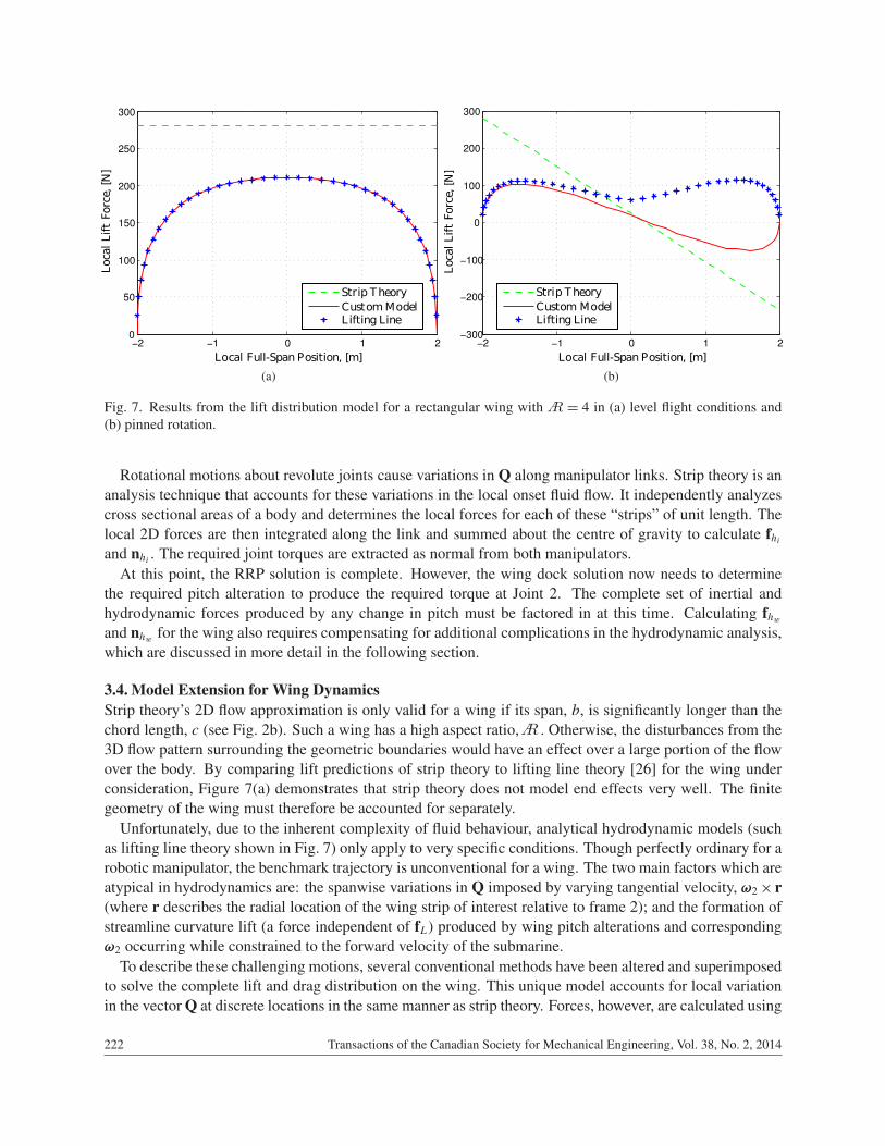
Fig. 7. Results from the lift distribution model for a rectangular wing with = 4 in (a) level flight conditions and(b) pinned rotation.
Rotational motions about revolute joints cause variations in Q along manipulator links. Strip theory is ananalysis technique that accounts for these variations in the local onset fluid flow. It independently analyzescross sectional areas of a body and determines the local forces for each of these “strips” of unit length. Thelocal 2D forces are then integrated along the link and summed about the centre of gravity to calculate fhiand nhi . The required joint torques are extracted as normal from both manipulators.
At this point, the RRP solution is complete. However, the wing dock solution now needs to determinethe required pitch alteration to produce the required torque at Joint 2. The complete set of inertial andhydrodynamic forces produced by any change in pitch must be factored in at this time. Calculating fhwand nhw for the wing also requires compensating for additional complications in the hydrodynamic analysis,which are discussed in more detail in the following section.
3.4. Model Extension for Wing DynamicsStrip theory’s 2D flow approximation is only valid for a wing if its span, b, is significantly longer than thechord length, c (see Fig. 2b). Such a wing has a high aspect ratio, . Otherwise, the disturbances from the3D flow pattern surrounding the geometric boundaries would have an effect over a large portion of the flowover the body. By comparing lift predictions of strip theory to lifting line theory [26] for the wing underconsideration, Figure 7(a) demonstrates that strip theory does not model end effects very well. The finitegeometry of the wing must therefore be accounted for separately.
Unfortunately, due to the inherent complexity of fluid behaviour, analytical hydrodynamic models (suchas lifting line theory shown in Fig. 7) only apply to very specific conditions. Though perfectly ordinary for arobotic manipulator, the benchmark trajectory is unconventional for a wing. The two main factors which areatypical in hydrodynamics are: the spanwise variations in Q imposed by varying tangential velocity, ω2× r(where r describes the radial location of the wing strip of interest relative to frame 2); and the formation ofstreamline curvature lift (a force independent of fL) produced by wing pitch alterations and correspondingω2 occurring while constrained to the forward velocity of the submarine.
To describe these challenging motions, several conventional methods have been altered and superimposedto solve the complete lift and drag distribution on the wing. This unique model accounts for local variationin the vector Q at discrete locations in the same manner as strip theory. Forces, however, are calculated using
222 Transactions of the Canadian Society for Mechanical Engineering, Vol. 38, No. 2, 2014
A
A

Fig. 8. Dynamic Matrix Control applied to the wing dock prototype.
Table 1. RRP dock maximum potential actuator torques required in the horizontal (Joint 1) and vertical (Joint 2) planesdue to drag, added mass, and mass effects as well as net resultant load; given a minimum wave period (Tmin) of 10.5 s,an average wave period (Tavg) of 13.8 s, and a maximum wave period (Tmax) of 17.5 s.
Joint Wave Period Drag [kNm] Added Mass [kNm] Mass [kNm] Net [kNm]Tmin 20.95 1.31 1.31 21.26
τ1 Tavg 22.02 1.12 1.12 22.29Tmax 22.23 0.91 0.91 22.40Tmin 1.74 0.74 0.74 2.05
τ2 Tavg 1.22 0.47 0.47 1.40Tmax 0.82 0.30 0.30 0.93
a modified solution to twisted wings in order to account for the overall alterations of the force distributionimposed by finite geometry. The pre-determined variations in α are treated as physical twist in a wingunder planar motion, and the typical Fourier expansion used in lifting line theory to solve for circulationis extended across the entire span. Streamline curvature lift is also examined at each point of interestand treated as local physical cambre in a wing under planar motion. Changes in local flow variations areevaluated each time step in order to provide an accurate measure of the total moments produced at Joint 2 byfhw and nhw .
4. MECHANISM CONTROLLER
The UNB research team will develop a controller for each mechanism to facilitate multi-body simulationsof the docking process. These controllers will provide the mechanisms with the ability to accurately followcommanded setpoint trajectories. However, strategic intelligence used to develop these trajectories duringthe docking process will be provided by other project collaborators.
Dependencies on link lengths for hydrodynamic effects, and indirect coupling between wing dock pitchand end effector motion present a difficult non-linear control problem for conventional gain-driven con-trollers such as Proportional-Integral (PI) and Proportional-Integral-Derivative (PID). A more advanced con-trol scheme such as Model Predictive Control (MPC) is required. As demonstrated by the basic schematic ofMPC (Fig. 8), these controllers are able to monitor multiple inputs and state variables, and use compensatedpredictions of plant responses to optimise the command signal sent to the plant based on minimising futureerrors [27].
Transactions of the Canadian Society for Mechanical Engineering, Vol. 38, No. 2, 2014 223

(a) (b)
Fig. 9. Resultant vertical motions for wing in water subjected to sinusoidal pitch inputs. (a) Vertical displacements and(b) corresponding angle of attack resulting from different pitch amplitudes, θ0 in rad, given a frequency ω = 1 rad/s.
5. MODEL RESULTS
The 3D model of the RRP fully mechanically actuated mechanism is theoretically compared to knownanalytical test cases. The model is used to evaluate the actuator loads numerically in both pure planarrotation and pure linear translation motions. These results are then compared analytically using strip theoryapproximation for each test case. This ensures the model is capable of evaluating the general plane motion ofa given link for generic trajectories. The numerical test cases correlate with the expected analytical values.The actuator loads are estimated by evaluating the model using the established benchmark trajectory. Thetorque requirements of the mechanically actuated RRP dock device are significant, as shown in Table 1.The primary contributor to the large torque requirements for the device is due to the drag which the bluffsubmerged body must overcome. The estimated loads of the RRP dock device suggests the mechanismmust be well streamlined in order to be a feasible solution. A well streamlined body can potentially reducethe drag experienced by an identical cylindrical body by up to 10 times its original magnitude [22]. Self-aligning fairings, unactuated fairings which align freely with the flow, could be incorporated into the RRPdock design to improve streamlining. Alternatively, a faired section could be used to both actuate and reducethe drag experienced by the device, such as with the wing dock.
Testing of the hydrodynamic model for the wing is being completed in stages to validate the modelon a component-by-component basis. The first stage ignores dynamics and develops a model capable ofcalculating non-symmetric distributions of fL and fD caused by ω2× r. Figure 7(b) shows predictions ofthe lift distribution produced at the point of maximum ω2 for the benchmark trajectory combined with aforward submarine velocity of 1 m/s. As expected, strip theory does not account for the finite geometryeffects. Whereas the solution to lifting line theory for finite wings cannot properly reflect the variations inQ. The custom model presents a blend of both factors. Figure 7(a) confirms the custom model successfullycollapses to the standard symmetric distribution during planar motions.
The second model stage constrains the wing to the forward motion of the submarine, but allows it to freelytranslate along the vertical axis of the submarine in response to prescribed pitch inputs. The model ignoresspanwise variability in Q, but accounts for both forms of lift, inertial forces due to pitching, added mass,and the affects of finite geometry. Figure 9(a) shows the vertical displacement resulting from a sinusoidalpitch input. The non-rotational wing achieves more than the required displacement of 1.2 m in 2.5 s for the
224 Transactions of the Canadian Society for Mechanical Engineering, Vol. 38, No. 2, 2014

fastest expected wave period of 10 s. The corresponding angle of attack in Fig. 9(b) predicts the wing willremain below stall which can occur at angles of attack as low as 10 or 12 degrees.
6. FUTURE WORK
Further work is being completed to combine the initial two hydrodynamic model stages for the wing. Re-sults collected from a physical prototype of a pitching and rotating wing section will be used to validate thiscomplete hydrodynamic model. Following validation, the hydrodynamic model will be integrated into therecursive EOM to combine with the remainder of the manipulator model. Controllers will then be developedfor both the mechanically and hydrodynamically actuated mechanisms. This will allow closed-loop simu-lations to to be performed in order to evaluate tracking errors when the devices are subject to disturbances.Measured errors and required actuator loads of the two concepts will be compared to determine the optimalsolution for recommendation to DRDC.
7. CONCLUSIONS
The dynamic models of two active autonomous dock mechanisms used for recovering AUVs to submergedsubmarines has been examined. Both serial manipulators are in an R⊥R⊥P configuration, with their baseattached to the midline of the submarine hull. While all the joints of one manipulator are directly driven bymotors, the second dock uses an actively pitched wing to indirectly drive its passive revolute joint, Joint 2.Necessary modifications to the recursive Newton–Euler dynamics have been introduced to address additionalfluid dynamics present in this submerged AUV recovery scenario. Standard lift distribution solutions havealso been modified to address rotational motions not typically present with fixed wings. Initial simulationsof both dock concepts suggest the benchmark trajectory is feasible, though analysis of joint torques suggeststhat the mechanically actuated manipulator will need to be adequately streamlined to reduce drag. Prototypesof both concepts will be tested in the future to validate these results.
ACKNOWLEDGEMENTS
This project is being coordinated by DRDC Atlantic and funded through the DRDC Technology InvestmentFund. Significant work has been undertaken by DRDC Atlantic and colleagues in DRDC Suffield, UNB,Dynamic Systems Analysis Ltd.
REFERENCES
1. “The Navy Unmanned Undersea Vehicle (UUV) master plan”, Technical Report, Department of the Navy, USA,www.navy.mil/navydata/technology/uuvmp.pdf, November 2004.
2. Scheutte, L., “Innovation opportunities in launch & recovery”, in Proceedings of the American Society ofNaval Engineers Launch and Recovery 2010 Symposium, Arlington, VA, USA, www.navalengineers.org/publications/symposiaproceedings/Pages/LaunchandRecovery2010.aspx, December 2010.
3. Watt, G., Carretero, J., Dubay, R. and MacKenzie, M., “Towards an automated active UUV dock on a slowlymoving submarine”, in Royal Institution of Naval Architects Warship 2011: Naval Submarines and UUVs, Bath,UK, June 2011.
4. Stokey, R., Purcell, M., Forrester, N., Austin, T., Goldsborough, R., Allen, B. and von Alt, C., “A docking systemfor REMUS, an autonomous underwater vehicle”, in Proceedings of OCEANS’97 MTS/IEEE Conference, Vol. 2,pp. 1132–1136, Halifax, NS, Canada, October 1997.
5. Allen, B., Austin, T., Forrester, N., Goldsborough, R., Kukulya, A., Packard, G., Purcell, M. and Stokey, R.,“Autonomous docking demonstrations with enhanced REMUS technology”, in Proceedings of OCEANS’06MTS/IEEE Conference, pp. 1–6, Boston, MA, USA, September 2006.
Transactions of the Canadian Society for Mechanical Engineering, Vol. 38, No. 2, 2014 225

6. Feezor, M., Sorrell, Y., Blankinship, P. and Bellingham, J., “Autonomous underwater vehicle homing/dockingvia electromagnetic guidance”. IEEE Journal of Oceanic Engineering, Vol. 26, No. 4, pp. 515–521, October2001.
7. Cowen, S., Briest, S. and Dombrowski, J., “Underwater docking of autonomous undersea vehicles using opticalterminal guidance”, in Proceedings OCEANS’97 MTS/IEEE Conference, Vol. 2, pp. 1143–1147, Halifax, NS,Canada, October 1997.
8. Park, J., Jun, B., Lee, P. and Oh, J., “Experiments on vision guided docking of an autonomous underwater vehicleusing one camera”. Ocean Engineering, Vol. 36, No. 1, pp. 48–61, January 2009.
9. Granger, R., Smith, J., Somlyody, S., Thomas, B. and Labosky, J., “UUV docking and recharging station:Demonstration results and next steps”, in Proceedings of the American Society of Naval Engineers Launch andRecovery 2012 Symposium, Baltimore, MD, USA, https://www.navalengineers.org/publications/symposiaproceedings/Pages/LR12Proceedings.aspx, November 2012.
10. “Launch And Recovery Systems (LARS)”, Corporate Website, Rolls-Royce Canada Limited – Naval Marine,www.brooke-ocean.com/handling_main.html, June 2012.
11. Lebans, G., Wilkie, K., Dubay, R., Crabtree, D. and Edmonds, T., “Telerobotic shipboard handling system”, inProceedings of OCEANS’97 MTS/IEEE Conference, Vol. 2, pp. 1237–1241, Halifax, NS, Canada, October 1997.
12. Selzer, M., “An unmanned underwater vehicle Launch, Recovery, and Onboard Handling and Servicing System(LROHSS) for use with unmanned surface vehicles”, in Proceedings of the American Society of Naval EngineersLaunch and Recovery 2010 Symposium, Arlington, VA, USA, www.navalengineers.org/publications/symposiaproceedings/Pages/LaunchandRecovery2010.aspx, December 2010.
13. “Unmanned Surface Vehicle (USV) payloads”, Corporate Website, Rolls-Royce Canada Limited – Naval Ma-rine, http://www.brooke-ocean.com/usv_main.html, October 2012.
14. Fedor, R., Simulation of a Launch and Recovery of an UUV to an Submarine. Master’s Thesis, KTH RoyalInstitute of Technology, Stockholm, Sweden, October 2009.
15. Siesjö, J., “SUBROV, a versatile submarine ROV system, or getting a grip on AUVs”, SAAB Seaeye, http://www.rov-online.com/subrov-rov/, November 2009.
16. Bashour, R., Ansay, M. and French, D., “MARV, NUWC’s Mid-sized Autonomous Reconfigurable Vehicle(MARV): Sub surface ship launch & recovery of a UUV efforts”, in Proceedings of the American Society ofNaval Engineers Launch and Recovery 2010 Symposium, Arlington, VA, USA, www.navalengineers.org/publications/symposiaproceedings/Pages/LaunchandRecovery2010.aspx, December 2010.
17. Stewart, M. and Pavlos, J., “A means to networked persistent undersea surveillance”, in Submarine TechnologySymposium, http://mseas.mit.edu/archive/PLUSNet/5stewamsPAF2.pdf, May 2006.
18. “Millennium plus ROV”, Corporate Website, Oceaneering International Inc., www.oceaneering.com/rovs/rov-systems/millennium-plus-rov/, 2012.
19. From, P., Gravdahl, J. and Abbeel, P., “On the influence of ship motion prediction accuracy on motion planningand control of robotic manipulators on seaborne platforms”, in IEEE International Conference on Robotics andAutomation, pp. 5281–5288, Anchorage, AK, USA, May 2010.
20. Aske, T., Barton, M. and MacKay, T., “Docking of unmanned underwater vehicles with submarines”. SeniorDesign Project Report, Department of Mechanical Engineering, University of New Brunswick, April 2011.
21. Cote, J., Gillis, C. and Hilton, K., “Docking autonomous underwater vehicles (UUV) on submarines”. SeniorDesign Project Report, Department of Mechanical Engineering, University of New Brunswick, April 2011.
22. Sharpkaya, T. and Issacson, M., Mechanics of Wave Forces on Offshore Structures. Van Nostrand ReinholdCompany, 1981.
23. Craig, J.J., Introduction to Robotics Mechanics and Control. 3rd ed. Pearson Prentice Hall, 2005.24. Watt, G., “Estimates for the added mass of a multi-component, deeply submerged vehicle part I: Theory and
program description”. Technical Memorandum 88/213, Defence Research Establishment Atlantic, October 1988.25. Sumer, B. and Fredsøe, J., Hydrodynamics around Cylindrical Structures. World Scientific Pub, London, 2006.26. Kuethe, A. and Chow, C., Foundations of Aerodynamics 4th ed. Wiley, 1986.27. Cutler, C. and Ramaker, B., “Dynamic matrix control – A computer control algorithm”, in Proceedings of the
Joint Automatic Control Conference, San Francisco, CA, USA, 1980.
226 Transactions of the Canadian Society for Mechanical Engineering, Vol. 38, No. 2, 2014