dynasty 300 sd, dx and lx - web.nchu.edu.twweb.nchu.edu.tw/~weite/chii/input-l07/miller.pdf ·...
TRANSCRIPT

Processes
Description
TIG (GTAW) Welding
Stick (SMAW) Welding
Arc Welding Power Source
OM-358 188 291K
September 2000
Dynasty 300 SD,DX And LX
230/460 Volt Models W/Autolink
400 Volt Models
And Non-CE Models
Visit our website at
www.MillerWelds.com

Miller Electric manufactures a full lineof welders and welding related equipment.For information on other quality Millerproducts, contact your local Miller distributorto receive the latest full line catalog orindividual catalog sheets. To locate your nearestdistributor or service agency call 1-800-4-A-Miller,or visit us at www.MillerWelds.com on the web.
Thank you and congratulations on choosing Miller. Nowyou can get the job done and get it done right. We knowyou don’t have time to do it any other way.
That’s why when Niels Miller first started building arcwelders in 1929, he made sure his products offeredlong-lasting value and superior quality. Like you, hiscustomers couldn’t afford anything less. Miller productshad to be more than the best they could be. They had tobe the best you could buy.
Today, the people that build and sell Miller products continue thetradition. They’re just as committed to providing equipment and servicethat meets the high standards of quality and value established in 1929.
This Owner’s Manual is designed to help you get the most out of yourMiller products. Please take time to read the Safety precautions. They willhelp you protect yourself against potential hazards on the worksite. We’ve
made installation and operation quick and easy.With Miller you can count on years of reliableservice with proper maintenance. And if forsome reason the unit needs repair, there’s aTroubleshooting section that will help youfigure out what the problem is. The parts listwill then help you to decide which exact partyou may need to fix the problem. Warranty andservice information for your particular modelare also provided.
Miller is the first weldingequipment manufacturer inthe U.S.A. to be registered tothe ISO 9001 Quality SystemStandard.
Working as hard as you do– every power source fromMiller is backed by the mosthassle-free warranty in thebusiness.
From Miller to You
Miller offers a TechnicalManual which providesmore detailed service andparts information for yourunit. To obtain a TechnicalManual, contact your localdistributor. Your distributorcan also supply you withWelding Process Manualssuch as SMAW, GTAW,GMAW, and GMAW-P.

The following terms areused interchangeablythroughout this manual:TIG = GTAWStick = SMAW
TABLE OF CONTENTS
SECTION 1 – SAFETY PRECAUTIONS - READ BEFORE USING 1. . . . . . . . . . . . . . . . . . . . . . . . . . . . 1-1. Symbol Usage 1. . . . . . . . . . . . . . . . . . . . . . . . . . . . . . . . . . . . . . . . . . . . . . . . . . . . . . . . . . . . . . . . 1-2. Arc Welding Hazards 1. . . . . . . . . . . . . . . . . . . . . . . . . . . . . . . . . . . . . . . . . . . . . . . . . . . . . . . . . . . 1-3. Additional Symbols for Installation, Operation, and Maintenance 3. . . . . . . . . . . . . . . . . . . . . . . 1-4. Principal Safety Standards 3. . . . . . . . . . . . . . . . . . . . . . . . . . . . . . . . . . . . . . . . . . . . . . . . . . . . . . 1-5. EMF Information 4. . . . . . . . . . . . . . . . . . . . . . . . . . . . . . . . . . . . . . . . . . . . . . . . . . . . . . . . . . . . . . .
SECTION 1 – CONSIGNES DE SECURITE – LIRE AVANT UTILISATION 5. . . . . . . . . . . . . . . . . . . . . 1-1. Signification des symboles 5. . . . . . . . . . . . . . . . . . . . . . . . . . . . . . . . . . . . . . . . . . . . . . . . . . . . . . 1-2. Dangers relatifs au soudage à l’arc 5. . . . . . . . . . . . . . . . . . . . . . . . . . . . . . . . . . . . . . . . . . . . . . . 1-3. Dangers supplémentaires en relation avec l’installation, le fonctionnement et la maintenance 71-4. Principales normes de sécurité 8. . . . . . . . . . . . . . . . . . . . . . . . . . . . . . . . . . . . . . . . . . . . . . . . . . . 1-5. Information sur les champs électromagnétiques 8. . . . . . . . . . . . . . . . . . . . . . . . . . . . . . . . . . . . .
SECTION 2 – DEFINITIONS (CE Models Only) 9. . . . . . . . . . . . . . . . . . . . . . . . . . . . . . . . . . . . . . . . . . . . 2-1. Warning Label Definitions 9. . . . . . . . . . . . . . . . . . . . . . . . . . . . . . . . . . . . . . . . . . . . . . . . . . . . . . . 2-2. Manufacturer’s Rating Label For CE Products Only 11. . . . . . . . . . . . . . . . . . . . . . . . . . . . . . . . . . 2-3. Symbols And Definitions 12. . . . . . . . . . . . . . . . . . . . . . . . . . . . . . . . . . . . . . . . . . . . . . . . . . . . . . . .
SECTION 3 – INSTALLATION 13. . . . . . . . . . . . . . . . . . . . . . . . . . . . . . . . . . . . . . . . . . . . . . . . . . . . . . . . . . . 3-1. Specifications 13. . . . . . . . . . . . . . . . . . . . . . . . . . . . . . . . . . . . . . . . . . . . . . . . . . . . . . . . . . . . . . . . . 3-2. Volt-Ampere Curves 13. . . . . . . . . . . . . . . . . . . . . . . . . . . . . . . . . . . . . . . . . . . . . . . . . . . . . . . . . . . . 3-3. Duty Cycle and Overheating 14. . . . . . . . . . . . . . . . . . . . . . . . . . . . . . . . . . . . . . . . . . . . . . . . . . . . . 3-4. Selecting a Location 15. . . . . . . . . . . . . . . . . . . . . . . . . . . . . . . . . . . . . . . . . . . . . . . . . . . . . . . . . . . . 3-5. 115 Volts AC Duplex Receptacle, Circuit Breaker CB1 (Optional), And Power Switch 16. . . . . 3-6. Weld Output Terminals and Selecting Cable Sizes 16. . . . . . . . . . . . . . . . . . . . . . . . . . . . . . . . . . . 3-7. Remote 14 Receptacle Information 17. . . . . . . . . . . . . . . . . . . . . . . . . . . . . . . . . . . . . . . . . . . . . . . 3-8. Remote Program Select Inputs (Optional For DX Models) 18. . . . . . . . . . . . . . . . . . . . . . . . . . . . 3-9. Automation Connection (LX Models Only) 19. . . . . . . . . . . . . . . . . . . . . . . . . . . . . . . . . . . . . . . . . . 3-10.Gas Connections 20. . . . . . . . . . . . . . . . . . . . . . . . . . . . . . . . . . . . . . . . . . . . . . . . . . . . . . . . . . . . . . 3-11.TIG HF Impulse/ Lift-Arc� DCEN (Direct Current Electrode Negative) Connections 20. . . . . . . 3-12.Front Panel Display For TIG HF Impulse DCEN (Direct Current Electrode Negative) 21. . . . . . 3-13.Stick DCEP (Direct Current Electrode Positive) Connections 22. . . . . . . . . . . . . . . . . . . . . . . . . . 3-14.Front Panel Display For Stick DCEP (Direct Current Electrode Positive) 23. . . . . . . . . . . . . . . . 3-15.Electrical Service Guide 24. . . . . . . . . . . . . . . . . . . . . . . . . . . . . . . . . . . . . . . . . . . . . . . . . . . . . . . . . 3-16.Connecting Input Power 25. . . . . . . . . . . . . . . . . . . . . . . . . . . . . . . . . . . . . . . . . . . . . . . . . . . . . . . . .
SECTION 4 – OPERATION 26. . . . . . . . . . . . . . . . . . . . . . . . . . . . . . . . . . . . . . . . . . . . . . . . . . . . . . . . . . . . . 4-1. Controls 26. . . . . . . . . . . . . . . . . . . . . . . . . . . . . . . . . . . . . . . . . . . . . . . . . . . . . . . . . . . . . . . . . . . . . . 4-2. Encoder Control 28. . . . . . . . . . . . . . . . . . . . . . . . . . . . . . . . . . . . . . . . . . . . . . . . . . . . . . . . . . . . . . . 4-3. Ammeter And Volt Meter 28. . . . . . . . . . . . . . . . . . . . . . . . . . . . . . . . . . . . . . . . . . . . . . . . . . . . . . . . 4-4. Polarity Control 28. . . . . . . . . . . . . . . . . . . . . . . . . . . . . . . . . . . . . . . . . . . . . . . . . . . . . . . . . . . . . . . . 4-5. Process Control 29. . . . . . . . . . . . . . . . . . . . . . . . . . . . . . . . . . . . . . . . . . . . . . . . . . . . . . . . . . . . . . . 4-6. Lift-Arc� And HF TIG Start Procedures 30. . . . . . . . . . . . . . . . . . . . . . . . . . . . . . . . . . . . . . . . . . . 4-7. Output Control 32. . . . . . . . . . . . . . . . . . . . . . . . . . . . . . . . . . . . . . . . . . . . . . . . . . . . . . . . . . . . . . . . . 4-8. Amperage Control 34. . . . . . . . . . . . . . . . . . . . . . . . . . . . . . . . . . . . . . . . . . . . . . . . . . . . . . . . . . . . . 4-9. Adjust Controls (Post Flow/DIG) 35. . . . . . . . . . . . . . . . . . . . . . . . . . . . . . . . . . . . . . . . . . . . . . . . . . 4-10.AC Wave Shape 36. . . . . . . . . . . . . . . . . . . . . . . . . . . . . . . . . . . . . . . . . . . . . . . . . . . . . . . . . . . . . . . 4-11.Pulser Control (DX And LX Models) 37. . . . . . . . . . . . . . . . . . . . . . . . . . . . . . . . . . . . . . . . . . . . . . . 4-12.Sequencer Controls (DX, LX And All CE Models) 38. . . . . . . . . . . . . . . . . . . . . . . . . . . . . . . . . . . . 4-13.Programmable TIG HF Impulse Start Polarity, Amperage And Time Modes 40. . . . . . . . . . . . . . 4-14.Reconfiguring 2T For 4T, 4T Momentary, Mini Logic Control, Or Spot (DX, LX
And All CE Models) 48. . . . . . . . . . . . . . . . . . . . . . . . . . . . . . . . . . . . . . . . . . . . . . . . . . . . . . . . . . . . . . . . 4-15.4T Specific Trigger Method (DX, LX And All CE Models) 52. . . . . . . . . . . . . . . . . . . . . . . . . . . . . . 4-16.Mini Logic Operation (DX, LX And All CE Models) 53. . . . . . . . . . . . . . . . . . . . . . . . . . . . . . . . . . . 4-17.Spot Control Operation (All Models) 54. . . . . . . . . . . . . . . . . . . . . . . . . . . . . . . . . . . . . . . . . . . . . . . 4-18.4T Momentary Operation (DX, LX And All CE Models) 55. . . . . . . . . . . . . . . . . . . . . . . . . . . . . . . 4-19.Arc Timer/Counter Display (All Models) 56. . . . . . . . . . . . . . . . . . . . . . . . . . . . . . . . . . . . . . . . . . . . 4-20.Lockout Functions 58. . . . . . . . . . . . . . . . . . . . . . . . . . . . . . . . . . . . . . . . . . . . . . . . . . . . . . . . . . . . . 4-21.Resetting Unit To Factory Default Settings (All Models) 61. . . . . . . . . . . . . . . . . . . . . . . . . . . . . . .
WARNINGThis product, when usedfor welding or cutting,produces fumes orgases which containchemicals known to theState of California tocause birth defects and,in some cases, cancer.(California Health &Safety Code Section25249.5 et seq.)
(Continued)

TABLE OF CONTENTSSECTION 5 – MAINTENANCE AND TROUBLESHOOTING 62. . . . . . . . . . . . . . . . . . . . . . . . . . . . . . . . .
5-1. Routine Maintenance 62. . . . . . . . . . . . . . . . . . . . . . . . . . . . . . . . . . . . . . . . . . . . . . . . . . . . . . . . . . . 5-2. Blowing Out Inside of Unit 62. . . . . . . . . . . . . . . . . . . . . . . . . . . . . . . . . . . . . . . . . . . . . . . . . . . . . . . 5-3. Voltmeter/Ammeter Help Displays 63. . . . . . . . . . . . . . . . . . . . . . . . . . . . . . . . . . . . . . . . . . . . . . . . 5-4. Troubleshooting 64. . . . . . . . . . . . . . . . . . . . . . . . . . . . . . . . . . . . . . . . . . . . . . . . . . . . . . . . . . . . . . .
SECTION 6 – ELECTRICAL DIAGRAM 66. . . . . . . . . . . . . . . . . . . . . . . . . . . . . . . . . . . . . . . . . . . . . . . . . . . SECTION 7 – HIGH FREQUENCY 68. . . . . . . . . . . . . . . . . . . . . . . . . . . . . . . . . . . . . . . . . . . . . . . . . . . . . . .
7-1. Welding Processes Requiring High Frequency 68. . . . . . . . . . . . . . . . . . . . . . . . . . . . . . . . . . . . . . 7-2. Incorrect Installation 68. . . . . . . . . . . . . . . . . . . . . . . . . . . . . . . . . . . . . . . . . . . . . . . . . . . . . . . . . . . . 7-3. Correct Installation 69. . . . . . . . . . . . . . . . . . . . . . . . . . . . . . . . . . . . . . . . . . . . . . . . . . . . . . . . . . . . .
SECTION 8 – SELECTING AND PREPARINGTUNGSTEN ELECTRODE 70. . . . . . . . . . . . . . . . . . . . . . . . . . . . . . . . . . . . . . . . . . . . . . . . . . . . . . . . . . . . . .
8-1. Selecting Tungsten Electrode 70. . . . . . . . . . . . . . . . . . . . . . . . . . . . . . . . . . . . . . . . . . . . . . . . . . . . 8-2. Safety Information About Tungsten 70. . . . . . . . . . . . . . . . . . . . . . . . . . . . . . . . . . . . . . . . . . . . . . . 8-3. Preparing Tungsten For AC Or DC Electrode Negative (DCEN) Welding 71. . . . . . . . . . . . . . . .
SECTION 9 – GUIDELINES FOR TIG WELDING (GTAW) 72. . . . . . . . . . . . . . . . . . . . . . . . . . . . . . . . . . . 9-1. Positioning The Torch 72. . . . . . . . . . . . . . . . . . . . . . . . . . . . . . . . . . . . . . . . . . . . . . . . . . . . . . . . . . . 9-2. Torch Movement During Welding 73. . . . . . . . . . . . . . . . . . . . . . . . . . . . . . . . . . . . . . . . . . . . . . . . . 9-3. Positioning Torch Tungsten For Various Weld Joints 74. . . . . . . . . . . . . . . . . . . . . . . . . . . . . . . . .
SECTION 10 – PARTS LIST 76. . . . . . . . . . . . . . . . . . . . . . . . . . . . . . . . . . . . . . . . . . . . . . . . . . . . . . . . . . . . OPTIONS AND ACCESSORIESWARRANTY

dec_con1 10/95
Declaration of Conformity ForEuropean Community (CE) Products
This information is provided for units with CE certification (see rating label on unit.)NOTE
Manufacturer’s Name: Miller Electric Mfg. Co.Manufacturer’s Address: 1635 W. Spencer Street
Appleton, WI 54914 USA
Declares that the product: Dynasty� 300 SD, DX, LXconforms to the following Directives and Standards:
Directives
Low Voltage Directive: 73/23/EEC
Machinery Directives: 89/392/EEC, 91/368/EEC, 93/C 133/04, 93/68/EEC
Electromagnetic Capability Directives: 89/336, 92/31/EEC
Standards
Safety Requirements for Arc Welding Equipment part 1: EN 60974-1: 1990
Arc Welding Equipment Part 1: Welding Power Sources: IEC 974-1(December 1996 – Draft revision)
Degrees of Protection provided by Enclosures (IP code): IEC 529: 1989
Insulation coordination for equipment within low-voltage systems:Part 1: Principles, requirements and tests: IEC 664-1: 1992
Electromagnetic compatibility (EMC) Product standard for arc welding equipment:EN50199: August 1995
European Contact: Mr. Luigi Vacchini, Managing DirectorMILLER Europe S.P.A.Via Privata Iseo20098 San GiulianoMilanese, Italy
Telephone: 39(02)98290-1Fax: 39(02)98281-552


OM-358 Page 1
SECTION 1 – SAFETY PRECAUTIONS - READ BEFORE USINGsom _nd_4/98
1-1. Symbol Usage
Means Warning! Watch Out! There are possible hazardswith this procedure! The possible hazards are shown inthe adjoining symbols.
� Marks a special safety message.
� Means “Note”; not safety related.
This group of symbols means Warning! Watch Out! possibleELECTRIC SHOCK, MOVING PARTS, and HOT PARTS hazards.Consult symbols and related instructions below for necessary actionsto avoid the hazards.
1-2. Arc Welding Hazards
� The symbols shown below are used throughout this manual tocall attention to and identify possible hazards. When you seethe symbol, watch out, and follow the related instructions toavoid the hazard. The safety information given below is onlya summary of the more complete safety information found inthe Safety Standards listed in Section 1-4. Read and follow allSafety Standards.
� Only qualified persons should install, operate, maintain, andrepair this unit.
� During operation, keep everybody, especially children, away.
ELECTRIC SHOCK can kill.
Touching live electrical parts can cause fatal shocksor severe burns. The electrode and work circuit iselectrically live whenever the output is on. The inputpower circuit and machine internal circuits are also
live when power is on. In semiautomatic or automatic wire welding, thewire, wire reel, drive roll housing, and all metal parts touching thewelding wire are electrically live. Incorrectly installed or improperlygrounded equipment is a hazard.
� Do not touch live electrical parts.
� Wear dry, hole-free insulating gloves and body protection.
� Insulate yourself from work and ground using dry insulating matsor covers big enough to prevent any physical contact with the workor ground.
� Do not use AC output in damp areas, if movement is confined, or ifthere is a danger of falling.
� Use AC output ONLY if required for the welding process.
� If AC output is required, use remote output control if present onunit.
� Disconnect input power or stop engine before installing orservicing this equipment. Lockout/tagout input power according toOSHA 29 CFR 1910.147 (see Safety Standards).
� Properly install and ground this equipment according to itsOwner’s Manual and national, state, and local codes.
� Always verify the supply ground – check and be sure that inputpower cord ground wire is properly connected to ground terminal indisconnect box or that cord plug is connected to a properlygrounded receptacle outlet.
� When making input connections, attach proper grounding conduc-tor first – double-check connections.
� Frequently inspect input power cord for damage or bare wiring –replace cord immediately if damaged – bare wiring can kill.
� Turn off all equipment when not in use.
� Do not use worn, damaged, undersized, or poorly spliced cables.
� Do not drape cables over your body.
� If earth grounding of the workpiece is required, ground it directlywith a separate cable.
� Do not touch electrode if you are in contact with the work, ground,or another electrode from a different machine.
� Use only well-maintained equipment. Repair or replace damagedparts at once. Maintain unit according to manual.
� Wear a safety harness if working above floor level.
� Keep all panels and covers securely in place.
� Clamp work cable with good metal-to-metal contact to workpieceor worktable as near the weld as practical.
� Insulate work clamp when not connected to workpiece to preventcontact with any metal object.
� Do not connect more than one electrode or work cable to anysingle weld output terminal.
SIGNIFICANT DC VOLTAGE exists after removal ofinput power on inverters.� Turn Off inverter, disconnect input power, and discharge input
capacitors according to instructions in Maintenance Sectionbefore touching any parts.
Welding produces fumes and gases. Breathingthese fumes and gases can be hazardous to yourhealth.
FUMES AND GASES can be hazardous.
� Keep your head out of the fumes. Do not breathe the fumes.
� If inside, ventilate the area and/or use exhaust at the arc to removewelding fumes and gases.
� If ventilation is poor, use an approved air-supplied respirator.
� Read the Material Safety Data Sheets (MSDSs) and themanufacturer’s instructions for metals, consumables, coatings,cleaners, and degreasers.
� Work in a confined space only if it is well ventilated, or whilewearing an air-supplied respirator. Always have a trained watch-person nearby. Welding fumes and gases can displace air andlower the oxygen level causing injury or death. Be sure the breath-ing air is safe.
� Do not weld in locations near degreasing, cleaning, or spraying op-erations. The heat and rays of the arc can react with vapors to formhighly toxic and irritating gases.
� Do not weld on coated metals, such as galvanized, lead, orcadmium plated steel, unless the coating is removed from the weldarea, the area is well ventilated, and if necessary, while wearing anair-supplied respirator. The coatings and any metals containingthese elements can give off toxic fumes if welded.
OM-358 Page 2
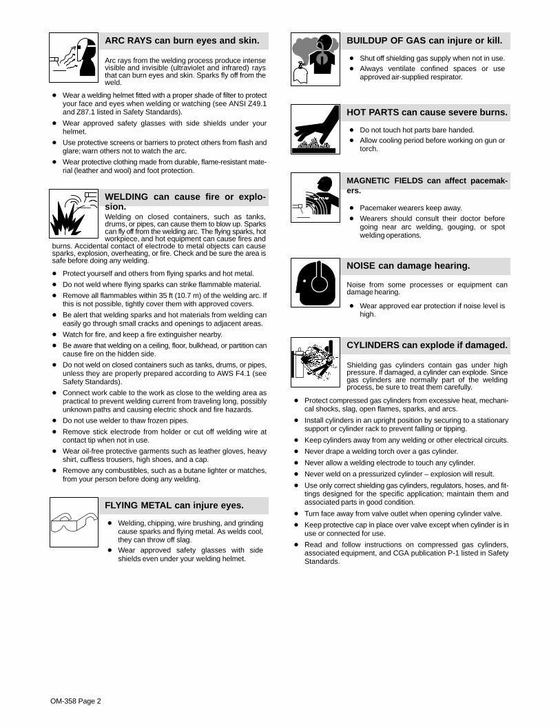
Arc rays from the welding process produce intensevisible and invisible (ultraviolet and infrared) raysthat can burn eyes and skin. Sparks fly off from theweld.
ARC RAYS can burn eyes and skin.
� Wear a welding helmet fitted with a proper shade of filter to protectyour face and eyes when welding or watching (see ANSI Z49.1and Z87.1 listed in Safety Standards).
� Wear approved safety glasses with side shields under yourhelmet.
� Use protective screens or barriers to protect others from flash andglare; warn others not to watch the arc.
� Wear protective clothing made from durable, flame-resistant mate-rial (leather and wool) and foot protection.
Welding on closed containers, such as tanks,drums, or pipes, can cause them to blow up. Sparkscan fly off from the welding arc. The flying sparks, hotworkpiece, and hot equipment can cause fires and
burns. Accidental contact of electrode to metal objects can causesparks, explosion, overheating, or fire. Check and be sure the area issafe before doing any welding.
WELDING can cause fire or explo-sion.
� Protect yourself and others from flying sparks and hot metal.
� Do not weld where flying sparks can strike flammable material.
� Remove all flammables within 35 ft (10.7 m) of the welding arc. Ifthis is not possible, tightly cover them with approved covers.
� Be alert that welding sparks and hot materials from welding caneasily go through small cracks and openings to adjacent areas.
� Watch for fire, and keep a fire extinguisher nearby.
� Be aware that welding on a ceiling, floor, bulkhead, or partition cancause fire on the hidden side.
� Do not weld on closed containers such as tanks, drums, or pipes,unless they are properly prepared according to AWS F4.1 (seeSafety Standards).
� Connect work cable to the work as close to the welding area aspractical to prevent welding current from traveling long, possiblyunknown paths and causing electric shock and fire hazards.
� Do not use welder to thaw frozen pipes.
� Remove stick electrode from holder or cut off welding wire atcontact tip when not in use.
� Wear oil-free protective garments such as leather gloves, heavyshirt, cuffless trousers, high shoes, and a cap.
� Remove any combustibles, such as a butane lighter or matches,from your person before doing any welding.
FLYING METAL can injure eyes.
� Welding, chipping, wire brushing, and grindingcause sparks and flying metal. As welds cool,they can throw off slag.
� Wear approved safety glasses with sideshields even under your welding helmet.
BUILDUP OF GAS can injure or kill.
� Shut off shielding gas supply when not in use.� Always ventilate confined spaces or use
approved air-supplied respirator.
HOT PARTS can cause severe burns.
� Do not touch hot parts bare handed.� Allow cooling period before working on gun or
torch.
MAGNETIC FIELDS can affect pacemak-ers.
� Pacemaker wearers keep away.� Wearers should consult their doctor before
going near arc welding, gouging, or spotwelding operations.
NOISE can damage hearing.
Noise from some processes or equipment candamage hearing.
� Wear approved ear protection if noise level ishigh.
Shielding gas cylinders contain gas under highpressure. If damaged, a cylinder can explode. Sincegas cylinders are normally part of the weldingprocess, be sure to treat them carefully.
CYLINDERS can explode if damaged.
� Protect compressed gas cylinders from excessive heat, mechani-cal shocks, slag, open flames, sparks, and arcs.
� Install cylinders in an upright position by securing to a stationarysupport or cylinder rack to prevent falling or tipping.
� Keep cylinders away from any welding or other electrical circuits.
� Never drape a welding torch over a gas cylinder.
� Never allow a welding electrode to touch any cylinder.
� Never weld on a pressurized cylinder – explosion will result.
� Use only correct shielding gas cylinders, regulators, hoses, and fit-tings designed for the specific application; maintain them andassociated parts in good condition.
� Turn face away from valve outlet when opening cylinder valve.
� Keep protective cap in place over valve except when cylinder is inuse or connected for use.
� Read and follow instructions on compressed gas cylinders,associated equipment, and CGA publication P-1 listed in SafetyStandards.
OM-358 Page 3
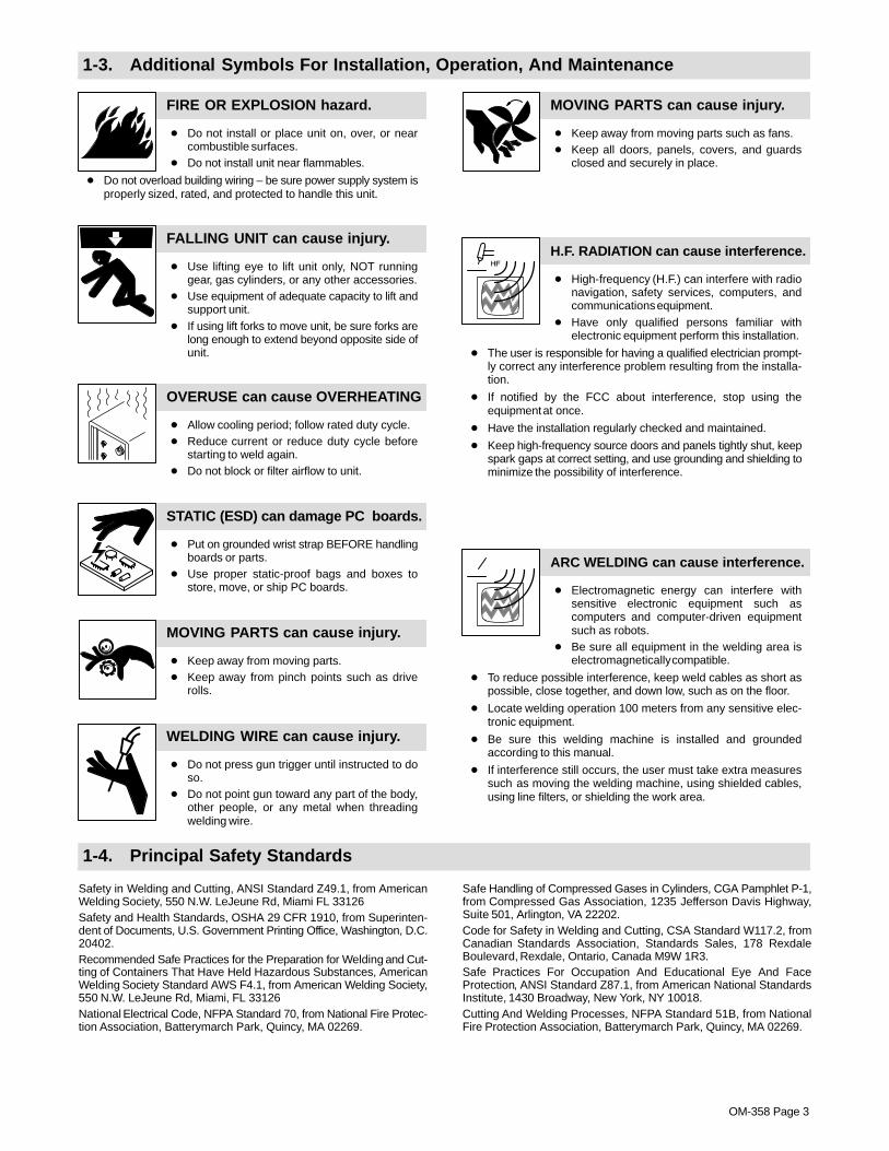
1-3. Additional Symbols For Installation, Operation, And Maintenance
FIRE OR EXPLOSION hazard.
� Do not install or place unit on, over, or nearcombustible surfaces.
� Do not install unit near flammables.
� Do not overload building wiring – be sure power supply system isproperly sized, rated, and protected to handle this unit.
FALLING UNIT can cause injury.
� Use lifting eye to lift unit only, NOT runninggear, gas cylinders, or any other accessories.
� Use equipment of adequate capacity to lift andsupport unit.
� If using lift forks to move unit, be sure forks arelong enough to extend beyond opposite side ofunit.
OVERUSE can cause OVERHEATING
� Allow cooling period; follow rated duty cycle.� Reduce current or reduce duty cycle before
starting to weld again.� Do not block or filter airflow to unit.
STATIC (ESD) can damage PC boards.
� Put on grounded wrist strap BEFORE handlingboards or parts.
� Use proper static-proof bags and boxes tostore, move, or ship PC boards.
MOVING PARTS can cause injury.
� Keep away from moving parts.� Keep away from pinch points such as drive
rolls.
WELDING WIRE can cause injury.
� Do not press gun trigger until instructed to doso.
� Do not point gun toward any part of the body,other people, or any metal when threadingwelding wire.
MOVING PARTS can cause injury.
� Keep away from moving parts such as fans.� Keep all doors, panels, covers, and guards
closed and securely in place.
H.F. RADIATION can cause interference.
� High-frequency (H.F.) can interfere with radionavigation, safety services, computers, andcommunications equipment.
� Have only qualified persons familiar withelectronic equipment perform this installation.
� The user is responsible for having a qualified electrician prompt-ly correct any interference problem resulting from the installa-tion.
� If notified by the FCC about interference, stop using theequipment at once.
� Have the installation regularly checked and maintained.
� Keep high-frequency source doors and panels tightly shut, keepspark gaps at correct setting, and use grounding and shielding tominimize the possibility of interference.
ARC WELDING can cause interference.
� Electromagnetic energy can interfere withsensitive electronic equipment such ascomputers and computer-driven equipmentsuch as robots.
� Be sure all equipment in the welding area iselectromagnetically compatible.
� To reduce possible interference, keep weld cables as short aspossible, close together, and down low, such as on the floor.
� Locate welding operation 100 meters from any sensitive elec-tronic equipment.
� Be sure this welding machine is installed and groundedaccording to this manual.
� If interference still occurs, the user must take extra measuressuch as moving the welding machine, using shielded cables,using line filters, or shielding the work area.
1-4. Principal Safety Standards
Safety in Welding and Cutting, ANSI Standard Z49.1, from AmericanWelding Society, 550 N.W. LeJeune Rd, Miami FL 33126Safety and Health Standards, OSHA 29 CFR 1910, from Superinten-dent of Documents, U.S. Government Printing Office, Washington, D.C.20402.Recommended Safe Practices for the Preparation for Welding and Cut-ting of Containers That Have Held Hazardous Substances, AmericanWelding Society Standard AWS F4.1, from American Welding Society,550 N.W. LeJeune Rd, Miami, FL 33126National Electrical Code, NFPA Standard 70, from National Fire Protec-tion Association, Batterymarch Park, Quincy, MA 02269.
Safe Handling of Compressed Gases in Cylinders, CGA Pamphlet P-1,from Compressed Gas Association, 1235 Jefferson Davis Highway,Suite 501, Arlington, VA 22202.Code for Safety in Welding and Cutting, CSA Standard W117.2, fromCanadian Standards Association, Standards Sales, 178 RexdaleBoulevard, Rexdale, Ontario, Canada M9W 1R3.Safe Practices For Occupation And Educational Eye And FaceProtection, ANSI Standard Z87.1, from American National StandardsInstitute, 1430 Broadway, New York, NY 10018.Cutting And Welding Processes, NFPA Standard 51B, from NationalFire Protection Association, Batterymarch Park, Quincy, MA 02269.

OM-358 Page 4
1-5. EMF Information
Considerations About Welding And The Effects Of Low FrequencyElectric And Magnetic FieldsWelding current, as it flows through welding cables, will cause electro-magnetic fields. There has been and still is some concern about suchfields. However, after examining more than 500 studies spanning 17years of research, a special blue ribbon committee of the NationalResearch Council concluded that: “The body of evidence, in thecommittee’s judgment, has not demonstrated that exposure to power-frequency electric and magnetic fields is a human-health hazard.”However, studies are still going forth and evidence continues to beexamined. Until the final conclusions of the research are reached, youmay wish to minimize your exposure to electromagnetic fields whenwelding or cutting.To reduce magnetic fields in the workplace, use the followingprocedures:
1. Keep cables close together by twisting or taping them.
2. Arrange cables to one side and away from the operator.
3. Do not coil or drape cables around your body.
4. Keep welding power source and cables as far away from opera-tor as practical.
5. Connect work clamp to workpiece as close to the weld as possi-ble.
About Pacemakers:Pacemaker wearers consult your doctor first. If cleared by your doctor,then following the above procedures is recommended.

OM-358 Page 5
SECTION 1 – CONSIGNES DE SECURITE – LIRE AVANTUTILISATION
som _nd_fre 4/98
1-1. Signification des symboles
Signifie Mise en garde ! Soyez vigilant ! Cette procédureprésente des risques de danger ! Ceux-ci sont identifiéspar des symboles adjacents aux directives.
� Identifie un message de sécurité particulier.
� Signifie NOTA ; n’est pas relatif à la sécurité.
Ce groupe de symboles signifie Mise en garde ! Soyez vigilant ! Il y a desrisques de danger reliés aux CHOCS ÉLECTRIQUES, aux PIÈCES ENMOUVEMENT et aux PIÈCES CHAUDES. Reportez-vous aux symboleset aux directives ci-dessous afin de connaître les mesures à prendre pouréviter tout danger.
1-2. Dangers relatifs au soudage à l’arc
� Les symboles présentés ci-après sont utilisés tout au long duprésent manuel pour attirer votre attention et identifier les risquesde danger. Lorsque vous voyez un symbole, soyez vigilant etsuivez les directives mentionnées afin d’éviter tout danger. Lesconsignes de sécurité présentées ci-après ne font que résumerl’information contenue dans les normes de sécurité énuméréesà la section 1-4. Veuillez lire et respecter toutes ces normes desécurité.
� L’installation, l’utilisation, l’entretien et les réparations ne doi-vent être confiés qu’à des personnes qualifiées.
� Au cours de l’utilisation, tenir toute personne à l’écart et plus par-ticulièrement les enfants.
UN CHOC ÉLECTRIQUE peut tuer.
Un simple contact avec des pièces électriques peutprovoquer une électrocution ou des blessures graves.L’électrode et le circuit de soudage sont sous tensiondès que l’appareil est sur ON. Le circuit d’entrée et lescircuits internes de l’appareil sont également sous
tension à ce moment-là. En soudage semi-automatique ou automatique,le fil, le dévidoir, le logement des galets d’entraînement et les piècesmétalliques en contact avec le fil de soudage sont sous tension. Desmatériels mal installés ou mal mis à la terre présentent un danger.
� Ne jamais toucher les pièces électriques sous tension.� Porter des gants et des vêtements de protection secs ne comportant
pas de trous.� S’isoler de la pièce et de la terre au moyen de tapis ou d’autres
moyens isolants suffisamment grands pour empêcher le contact phy-sique éventuel avec la pièce ou la terre.
� Ne pas se servir de source électrique àcourant électrique dans les zoneshumides, dans les endroits confinés ou là où on risque de tomber.
� Se servir d’une source électrique àcourant électrique UNIQUEMENT si leprocédé de soudage le demande.
� Si l’utilisation d’une source électrique àcourant électrique s’avère néces-saire, se servir de la fonction de télécommande si l’appareil en est équipé.
� Couper l’alimentation ou arrêter le moteur avant de procéder à l’instal-lation, à la réparation ou à l’entretien de l’appareil. Déverrouillerl’alimentation selon la norme OSHA 29 CFR 1910.147 (voir normes desécurité).
� Installer et mettre à la terre correctement cet appareil conformément àson manuel d’utilisation et aux codes nationaux, provinciaux etmunicipaux.
� Toujours vérifier la terre du cordon d’alimentation – Vérifier et s’assu-rer que le fil de terre du cordon d’alimentation est bien raccordé à laborne de terre du sectionneur ou que la fiche du cordon est raccordéeà une prise correctement mise à la terre.
� En effectuant les raccordements d’entrée fixer d’abord le conducteurde mise à la terre approprié et contre-vérifier les connexions.
� Vérifier fréquemment le cordon d’alimentation pour voir s’il n’est pasendommagé ou dénudé – remplacer le cordon immédiatement s’il estendommagé – un câble dénudé peut provoquer une électrocution.
� Mettre l’appareil hors tension quand on ne l’utilise pas.� Ne pas utiliser des câbles usés, endommagés, de grosseur insuffi-
sante ou mal épissés.� Ne pas enrouler les câbles autour du corps.� Si la pièce soudée doit être mise à la terre, le faire directement avec un
câble distinct.� Ne pas toucher l’électrode quand on est en contact avec la pièce, la
terre ou une électrode provenant d’une autre machine.
� N’utiliser qu’un matériel en bon état. Réparer ou remplacer sur-le-champ les pièces endommagées. Entretenir l’appareil conformémentà ce manuel.
� Porter un harnais de sécurité quand on travaille en hauteur.
� Maintenir solidement en place tous les panneaux et capots.
� Fixer le câble de retour de façon à obtenir un bon contact métal-métalavec la pièce à souder ou la table de travail, le plus près possible de lasoudure.
� Isoler la pince de masse quand pas mis à la pièce pour éviter le contactavec tout objet métallique.
Il y a DU COURANT CONTINU IMPORTANT dans lesconvertisseurs après la suppression de l’alimenta-tion électrique.� Arrêter les convertisseurs, débrancher le courant électrique, et dé-
charger les condensateurs d’alimentation selon les instructionsindiquées dans la partie entretien avant de toucher les pièces.
Le soudage génère des fumées et des gaz. Leurinhalation peut être dangereux pour votre santé.
� Eloigner votre tête des fumées. Ne pas respirerles fumées.
� A l’intérieur, ventiler la zone et/ou utiliser un échappement au niveaude l’arc pour l’évacuation des fumées et des gaz de soudage.
� Si la ventilation est insuffisante, utiliser un respirateur à alimenta-tion d’air homologué.
� Lire les spécifications de sécurité des matériaux (MSDSs) et lesinstructions du fabricant concernant les métaux, les consomma-bles, les revêtements, les nettoyants et les dégraisseurs.
� Travailler dans un espace fermé seulement s’il est bien ventilé ou enportant un respirateur à alimentation d’air. Demander toujours à unsurveillant dûment formé de se tenir à proximité. Des fumées et desgaz de soudage peuvent déplacer l’air et abaisser le niveau d’oxy-gène provoquant des blessures ou des accidents mortels. S’assu-rer que l’air de respiration ne présente aucun danger.
� Ne pas souder dans des endroits situés à proximité d’opérations dedégraissage, de nettoyage ou de pulvérisation. La chaleur et lesrayons de l’arc peuvent réagir en présence de vapeurs et former desgaz hautement toxiques et irritants.
� Ne pas souder des métaux munis d’un revêtement, tels que l’aciergalvanisé, plaqué en plomb ou au cadmium à moins que le revête-ment n’ait été enlevé dans la zone de soudure, que l’endroit soit bienventilé, et si nécessaire, en portant un respirateur à alimentationd’air. Les revêtements et tous les métaux renfermant ces élémentspeuvent dégager des fumées toxiques en cas de soudage.
LES FUMÉES ET LES GAZ peuventêtre dangereux.

OM-358 Page 6
Le rayonnement de l’arc du procédé de soudagegénère des rayons visibles et invisibles intenses(ultraviolets et infrarouges) susceptibles de provoquer
des brûlures dans les yeux et sur la peau. Des étincelles sont projetéespendant le soudage.
LES RAYONS DE L’ARC peuvent pro-voquer des brûlures dans les yeux etsur la peau.
� Porter un casque de soudage muni d’un écran de filtre approprié pourprotéger votre visage et vos yeux pendant le soudage ou pour regar-der (voir ANSI Z49.1 et Z87.1 énuméré dans les normes de sécurité).
� Porter des protections approuvés pour les oreilles si le niveau sondre esttrop élevé.
� Utiliser des écrans ou des barrières pour protéger des tiers de l’éclairet de l’éblouissement; demander aux autres personnes de ne pas re-garder l’arc.
� Porter des vêtements de protection constitué dans une matière dura-ble, résistant au feu (cuir ou laine) et une protection des pieds.
Le soudage effectué sur des conteneurs fermés telsque des réservoirs, tambours ou des conduites peutprovoquer leur éclatement. Des étincelles peuvent êtreprojetées de l’arc de soudure. La projection d’étincel-
les, des pièces chaudes et des équipements chauds peut provoquer desincendies et des brûlures. Le contact accidentel de l’électrode avec desobjets métalliques peut provoquer des étincelles, une explosion, unsurchauffement ou un incendie. Avant de commencer le soudage, vérifieret s’assurer que l’endroit ne présente pas de danger.
LE SOUDAGE peut provoquer unincendie ou une explosion.
� Se protéger et d’autres personnes de la projection d’étincelles et demétal chaud.
� Ne pas souder dans un endroit là où des étincelles peuvent tomber surdes substances inflammables.
� Déplacer toutes les substances inflammables à une distance de 10,7m de l’arc de soudage. En cas d’impossibilité les recouvrir soigneuse-ment avec des protections homologués.
� Des étincelles et des matériaux chauds du soudage peuvent facile-ment passer dans d’autres zones en traversant de petites fissures etdes ouvertures.
� Surveiller tout déclenchement d’incendie et tenir un extincteur à proxi-mité.
� Le soudage effectué sur un plafond, plancher, paroi ou séparationpeut déclencher un incendie de l’autre côté.
� Ne pas effectuer le soudage sur des conteneurs fermés tels que desréservoirs, tambours, ou conduites, à moins qu’ils n’aient été prépa-rés correctement conformément à AWS F4.1 (voir les normes desécurité).
� Brancher le câble sur la pièce le plus près possible de la zone de sou-dage pour éviter le transport du courant sur une longue distance pardes chemins inconnus éventuels en provoquant des risques d’élec-trocution et d’incendie.
� Ne pas utiliser le poste de soudage pour dégeler des conduites ge-lées.
� En cas de non utilisation, enlever la baguette d’électrode du porte-électrode ou couper le fil à la pointe de contact.
� Porter des vêtements de protection dépourvus d’huile tels que desgants en cuir, une chemise en matériau lourd, des pantalons sans re-vers, des chaussures hautes et un couvre chef.
� Avant de souder, retirer toute substance combustible de vos pochestelles qu’un allumeur au butane ou des allumettes.
DES PARTICULES VOLANTESpeuvent blesser les yeux.
� Le soudage, l’écaillement, le passage de la pièceà la brosse en fil de fer, et le meulage génèrentdes étincelles et des particules métalliques vo-
lantes. Pendant la période de refroidissement des soudures, elles ris-quent de projeter du laitier.� Porter des lunettes de sécurité avec écrans latéraux ou un écran facial.
LES ACCUMULATIONS DE GAZ ris-quent de provoquer des blessures oumême la mort.
� Fermer l’alimentation du gaz protecteur en cas denon utilisation.
� Veiller toujours à bien aérer les espaces confinés ou se servir d’un respi-rateur d’adduction d’air homologué.
DES PIÈCES CHAUDES peuvent pro-voquer des brûlures graves.
� Ne pas toucher des parties chaudes à mains nues� Prévoir une période de refroidissement avant
d’utiliser le pistolet ou la torche.
LES CHAMPS MAGNÉTIQUES peuventaffecter les stimulateurs cardiaques.
� Porteurs de stimulateur cardiaque, restez à distance.� Les porteurs d’un stimulateur cardiaque doivent
d’abord consulter leur médecin avant de s’approcherdes opérations de soudage à l’arc, de gougeage oude soudage par points.
LE BRUIT peut affecter l’ouïe.
Le bruit des processus et des équipements peut affecterl’ouïe.
� Porter des protections approuvés pour les oreilles sile niveau sondre est trop élevé.
Des bouteilles de gaz protecteur contiennent du gazsous haute pression. Si une bouteille est endomma-gée, elle peut exploser. Du fait que les bouteilles de gazfont normalement partie du procédé de soudage, les
manipuler avec précaution.
� Protéger les bouteilles de gaz comprimé d’une chaleur excessive,des chocs mécaniques, du laitier, des flammes ouvertes, des étin-celles et des arcs.
� Placer les bouteilles debout en les fixant dans un support stationnai-re ou dans un porte-bouteilles pour les empêcher de tomber ou dese renverser.
� Tenir les bouteilles éloignées des circuits de soudage ou autres cir-cuits électriques.
� Ne jamais placer une torche de soudage sur une bouteille à gaz.� Une électrode de soudage ne doit jamais entrer en contact avec une
bouteille.� Ne jamais souder une bouteille pressurisée – risque d’explosion.� Utiliser seulement des bouteilles de gaz protecteur, régulateurs,
tuyaux et raccords convenables pour cette application spécifique;les maintenir ainsi que les éléments associés en bon état.
� Ne pas tenir la tête en face de la sortie en ouvrant la soupape de labouteille.
� Maintenir le chapeau de protection sur la soupape, sauf en cas d’uti-lisation ou de branchement de la bouteille.
� Lire et suivre les instructions concernant les bouteilles de gaz com-primé, les équipements associés et les publications P-1 CGA énu-mérées dans les normes de sécurité.
Si des BOUTEILLES sont endomma-gées, elles pourront exploser.
OM-358 Page 7
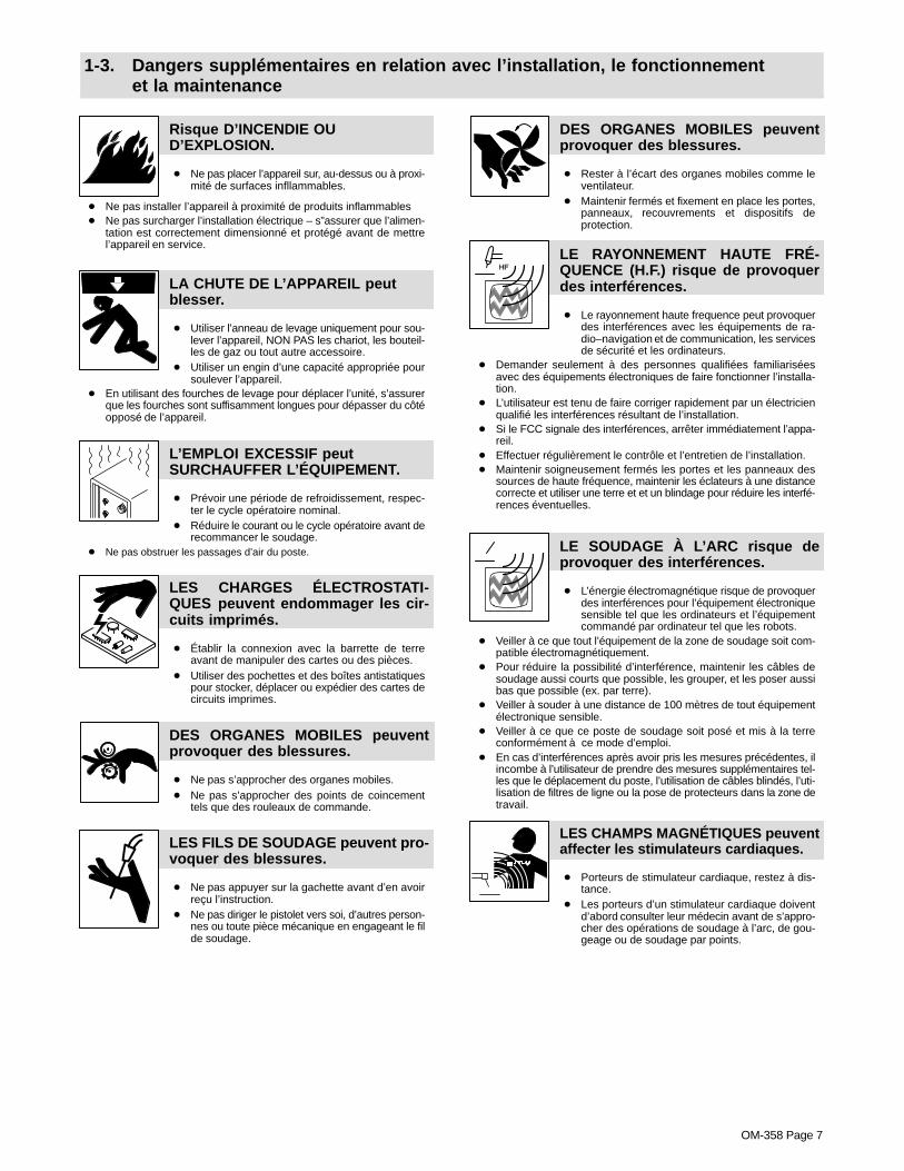
1-3. Dangers supplémentaires en relation avec l’installation, le fonctionnementet la maintenance
Risque D’INCENDIE OUD’EXPLOSION.
� Ne pas placer l’appareil sur, au-dessus ou à proxi-mité de surfaces infllammables.
� Ne pas installer l’appareil à proximité de produits inflammables� Ne pas surcharger l’installation électrique – s”assurer que l’alimen-
tation est correctement dimensionné et protégé avant de mettrel’appareil en service.
LA CHUTE DE L’APPAREIL peutblesser.
� Utiliser l’anneau de levage uniquement pour sou-lever l’appareil, NON PAS les chariot, les bouteil-les de gaz ou tout autre accessoire.
� Utiliser un engin d’une capacité appropriée poursoulever l’appareil.
� En utilisant des fourches de levage pour déplacer l’unité, s’assurerque les fourches sont suffisamment longues pour dépasser du côtéopposé de l’appareil.
L’EMPLOI EXCESSIF peutSURCHAUFFER L’ÉQUIPEMENT.
� Prévoir une période de refroidissement, respec-ter le cycle opératoire nominal.
� Réduire le courant ou le cycle opératoire avant derecommancer le soudage.
� Ne pas obstruer les passages d’air du poste.
LES CHARGES ÉLECTROSTATI-QUES peuvent endommager les cir-cuits imprimés.
� Établir la connexion avec la barrette de terreavant de manipuler des cartes ou des pièces.
� Utiliser des pochettes et des boîtes antistatiquespour stocker, déplacer ou expédier des cartes decircuits imprimes.
DES ORGANES MOBILES peuventprovoquer des blessures.
� Ne pas s’approcher des organes mobiles.� Ne pas s’approcher des points de coincement
tels que des rouleaux de commande.
LES FILS DE SOUDAGE peuvent pro-voquer des blessures.
� Ne pas appuyer sur la gachette avant d’en avoirreçu l’instruction.
� Ne pas diriger le pistolet vers soi, d’autres person-nes ou toute pièce mécanique en engageant le filde soudage.
DES ORGANES MOBILES peuventprovoquer des blessures.
� Rester à l’écart des organes mobiles comme leventilateur.
� Maintenir fermés et fixement en place les portes,panneaux, recouvrements et dispositifs deprotection.
LE RAYONNEMENT HAUTE FRÉ-QUENCE (H.F.) risque de provoquerdes interférences.
� Le rayonnement haute frequence peut provoquerdes interférences avec les équipements de ra-dio–navigation et de communication, les servicesde sécurité et les ordinateurs.
� Demander seulement à des personnes qualifiées familiariséesavec des équipements électroniques de faire fonctionner l’installa-tion.
� L’utilisateur est tenu de faire corriger rapidement par un électricienqualifié les interférences résultant de l’installation.
� Si le FCC signale des interférences, arrêter immédiatement l’appa-reil.
� Effectuer régulièrement le contrôle et l’entretien de l’installation.� Maintenir soigneusement fermés les portes et les panneaux des
sources de haute fréquence, maintenir les éclateurs à une distancecorrecte et utiliser une terre et et un blindage pour réduire les interfé-rences éventuelles.
LE SOUDAGE À L’ARC risque deprovoquer des interférences.
� L’énergie électromagnétique risque de provoquerdes interférences pour l’équipement électroniquesensible tel que les ordinateurs et l’équipementcommandé par ordinateur tel que les robots.
� Veiller à ce que tout l’équipement de la zone de soudage soit com-patible électromagnétiquement.
� Pour réduire la possibilité d’interférence, maintenir les câbles desoudage aussi courts que possible, les grouper, et les poser aussibas que possible (ex. par terre).
� Veiller à souder à une distance de 100 mètres de tout équipementélectronique sensible.
� Veiller à ce que ce poste de soudage soit posé et mis à la terreconformément à ce mode d’emploi.
� En cas d’interférences après avoir pris les mesures précédentes, ilincombe à l’utilisateur de prendre des mesures supplémentaires tel-les que le déplacement du poste, l’utilisation de câbles blindés, l’uti-lisation de filtres de ligne ou la pose de protecteurs dans la zone detravail.
LES CHAMPS MAGNÉTIQUES peuventaffecter les stimulateurs cardiaques.
� Porteurs de stimulateur cardiaque, restez à dis-tance.
� Les porteurs d’un stimulateur cardiaque doiventd’abord consulter leur médecin avant de s’appro-cher des opérations de soudage à l’arc, de gou-geage ou de soudage par points.

OM-358 Page 8
1-4. Principales normes de sécurité
Safety in Welding and Cutting, norme ANSI Z49.1, de l’American Wel-ding Society, 550 N.W. Lejeune Rd, Miami FL 33126
Safety and Health Sandards, OSHA 29 CFR 1910, du Superintendentof Documents, U.S. Government Printing Office, Washington, D.C.20402.
Recommended Safe Practice for the Preparation for Welding and Cut-ting of Containers That Have Held Hazardous Substances, norme AWSF4.1, de l’American Welding Society, 550 N.W. Lejeune Rd, Miami FL33126
National Electrical Code, NFPA Standard 70, de la National Fire Protec-tion Association, Batterymarch Park, Quincy, MA 02269.
Safe Handling of Compressed Gases in Cylinders, CGA Pamphlet P-1,de la Compressed Gas Association, 1235 Jefferson Davis Highway,Suite 501, Arlington, VA 22202.
Règles de sécurité en soudage, coupage et procédés connexes, normeCSA W117.2, de l’Association canadienne de normalisation, vente denormes, 178 Rexdale Boulevard, Rexdale (Ontario) Canada M9W 1R3.
Safe Practices For Occupation And Educational Eye And Face Protec-tion, norme ANSI Z87.1, de l’American National Standards Institute,1430 Broadway, New York, NY 10018.
Cutting and Welding Processes, norme NFPA 51B, de la National FireProtection Association, Batterymarch Park, Quincy, MA 02269.
1-5. Information sur les champs électromagnétiques
Données sur le soudage électrique et sur les effets, pour l’organisme,des champs magnétiques basse fréquence
Le courant de soudage, pendant son passage dans les câbles de sou-dage, causera des champs électromagnétiques. Il y a eu et il y a encoreun certain souci à propos de tels champs. Cependant, après avoir ex-aminé plus de 500 études qui ont été faites pendant une période derecherche de 17 ans, un comité spécial ruban bleu du National Re-search Council a conclu: “L’accumulation de preuves, suivant lejugement du comité, n’a pas démontré que l’exposition aux champsmagnétiques et champs électriques à haute fréquence représente unrisque à la santé humaine”. Toutefois, des études sont toujours en courset les preuves continuent à être examinées. En attendant que les con-clusions finales de la recherche soient établies, il vous seraitsouhaitable de réduire votre exposition aux champs électromagnéti-ques pendant le soudage ou le coupage.
Afin de réduire les champs électromagnétiques dans l’environnementde travail, respecter les consignes suivantes :
1 Garder les câbles ensembles en les torsadant ou en lesattachant avec du ruban adhésif.
2 Mettre tous les câbles du côté opposé de l’opérateur.
3 Ne pas courber pas et ne pas entourer pas les câbles autour devotre corps.
4 Garder le poste de soudage et les câbles le plus loin possible devous.
5 Relier la pince de masse le plus près possible de la zone desoudure.
Consignes relatives aux stimulateurs cardiaques :
Les personnes qui portent un stimulateur cardiaque doivent avant toutconsulter leur docteur. Si vous êtes déclaré apte par votre docteur, il estalors recommandé de respecter les consignes ci–dessus.

OM-358 Page 9
SECTION 2 – DEFINITIONS (CE Models Only)
2-1. Warning Label Definitions
Warning! Watch Out! There arepossible hazards as shown by thesymbols.
1 Electric shock from weldingelectrode or wiring can kill.
1.1 Wear dry insulating gloves.Do not touch electrode withbare hand. Do not wear wet ordamaged gloves.
1.2 Protect yourself from electricshock by insulating yourselffrom work and ground.
1.3 Disconnect input plug orpower before working onmachine.
2 Breathing welding fumes canbe hazardous to your health.
2.1 Keep your head out of thefumes.
2.2 Use forced ventilation or localexhaust to remove the fumes.
2.3 Use ventilating fan to removefumes.
3 Welding sparks can causeexplosion or fire.
3.1 Keep flammables away fromwelding. Do not weld nearflammables.
3.2 Welding sparks can causefires. Have a fire extinguishernearby, and have awatchperson ready to use it.
3.3 Do not weld on drums or anyclosed containers.
4 Arc rays can burn eyes andinjure skin.
4.1 Wear hat and safety glasses.Use ear protection and buttonshirt collar. Use weldinghelmet with correct shade offilter. Wear complete bodyprotection.
5 Become trained and read theinstructions before working onthe machine or welding.
6 Do not remove or paint over(cover) the label.
1 1.1 1.2 1.3
3 3.1 3.2 3.3
4 4.1
+
2 2.1 2.2
+
+
5 6
+
2.3
S-179 310
OM-358 Page 10
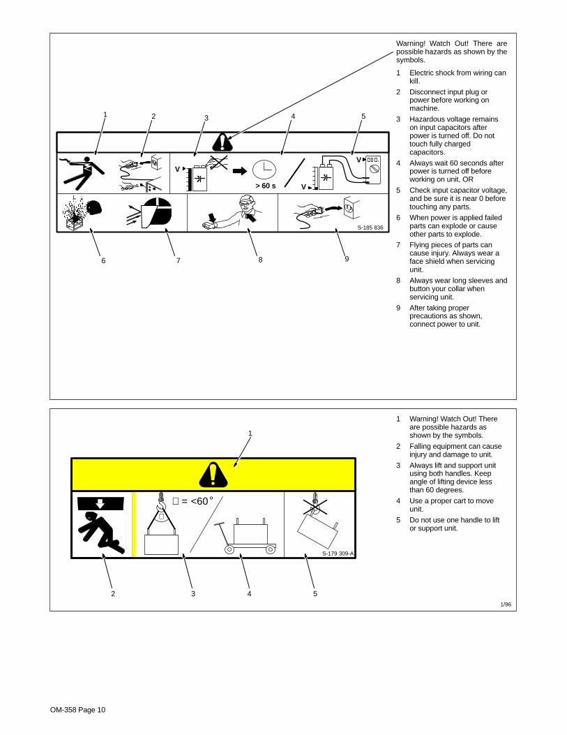
Warning! Watch Out! There arepossible hazards as shown by thesymbols.
1 Electric shock from wiring cankill.
2 Disconnect input plug orpower before working onmachine.
3 Hazardous voltage remainson input capacitors afterpower is turned off. Do nottouch fully chargedcapacitors.
4 Always wait 60 seconds afterpower is turned off beforeworking on unit, OR
5 Check input capacitor voltage,and be sure it is near 0 beforetouching any parts.
6 When power is applied failedparts can explode or causeother parts to explode.
7 Flying pieces of parts cancause injury. Always wear aface shield when servicingunit.
8 Always wear long sleeves andbutton your collar whenservicing unit.
9 After taking properprecautions as shown,connect power to unit.
S-185 836
> 60 s
VV
V
1 2 3 4 5
6 7 8 9
S-179 309-A
∠ = <60°∠
1 Warning! Watch Out! Thereare possible hazards asshown by the symbols.
2 Falling equipment can causeinjury and damage to unit.
3 Always lift and support unitusing both handles. Keepangle of lifting device lessthan 60 degrees.
4 Use a proper cart to moveunit.
5 Do not use one handle to liftor support unit.
1/96
1
2 3 4 5

OM-358 Page 11
2-2. Manufacturer ’s Rating Label For CE Products Only
ST-189 968-A
� For label locationsee Section 3-4.

OM-358 Page 12
2-3. Symbols And Definitions
A Amperes Panel–LocalGas Tungsten ArcWelding (GTAW)
Shielded Metal ArcWelding (SMAW)
V Volts Input 3 Phase Static FrequencyConverter-Transformer-Rectifier
Output Circuit Breaker Remote Lift-Arc (GTAW)
Protective Earth(Ground) Postflow Timer Preflow Timer S Seconds
On Off Positive Negative
AlternatingCurrent Gas Input Gas Output I2
Rated WeldingCurrent
X Duty Cycle Direct Current Line Connection U2Conventional Load
Voltage
U1Primary Voltage IP Degree Of
Protection I1maxRated MaximumSupply Current I1eff
Maximum EffectiveSupply Current
U0Rated No Load
Voltage (Average)Pulse Background
Amperage Initial AmperageIncrease/Decrease
Of Quantity
Normal Trigger Op-eration (GTAW)
Two-Step TriggerOperation (GTAW)
Four-Step TriggerOperation (GTAW) Percent
Hz HertzRecall From
Memory Arc Force (DIG)Impulse Starting
(GTAW)
Final Slope Final AmperagePulse Percent
On Time Initial Slope
Contactor Control(Stick) Pulser
TIG Weld AmpsAnd Peak Amps
While PulsingPulse Frequency
Work ElectrodeBalance % EN
Time (AC GTAW)Process
Unit may be usedin environmentswith increased
hazard of electricshock
Sequence Adjust

OM-358 Page 13
SECTION 3 – INSTALLATION
3-1. Specifications
A. For Multivoltage Units
AmperageMaximum Amperes Input at Rated Load Output 60 Hz
Input Power Rated Welding Output
AmperageRange
Open-CircuitVoltage DC 230 V 460 V KVA KW
250 A @ 30 Volts AC, 40%Duty Cycle
26.3*.27
17.9*.15
14.2*.09
10.5*.04
Three Phase200 A @ 28 Volts DC, 40%
Duty Cycle
5–300 9520.5*.27
13.4*.15
8.4*.09
7.6*.04
250 A @ 30 Volts AC, 40%Duty Cycle
62.6*.33
32.2*.18
14.8*.10
10.4*.07
Single Phase200 A @ 28 Volts DC, 40%
Duty Cycle
5–300 9544
*.3325.8*.18
11.9*.1
8.1*.07
*While idling
B. For Single Voltage Units
Rated Welding Output Amperage Range
MaximumOpen-CircuitVoltage DC
Amperes Input At RatedOutput, 50Hz - Three-Phase
400 V KVA KW
250 A @ 30 VAC,40% Duty Cycle
5 – 300 95 VDC 20.2 (0.13*) 14.0 (0.09*) 10.5 (0.04*)
200 A @ 28 VDC,40% Duty Cycle
5 – 300 95 VDC 15.1 (0.13*) 10.5 (0.09*) 7.5 (0.04*)
*While idling
3-2. Volt-Ampere Curves
SA-185 793 / SA-186 294
Volt-ampere curves show mini-mum and maximum voltage andamperage output capabilities ofunit. Curves of other settings fall be-tween curves shown.

OM-358 Page 14
3-3. Duty Cycle and Overheating
4 Minutes Welding 6 Minutes Resting
Duty Cycle is the percentage of 10minutes that unit can weld at ratedload without overheating.
If unit overheats, output stops, aHelp message is displayed (seeSection 5-3), and cooling fan runs.Wait fifteen minutes for unit to cool.Reduce amperage or voltage, orduty cycle before welding.
� Exceeding duty cycle candamage unit and voidwarranty.
250 A @ 40% Duty Cycle For AC
Overheating
0
15
A or V
ORReduce Duty CycleMinutes
sduty1 5/95 / SA-185 794
200 A @ 40% Duty Cycle For DC
OM-358 Page 15
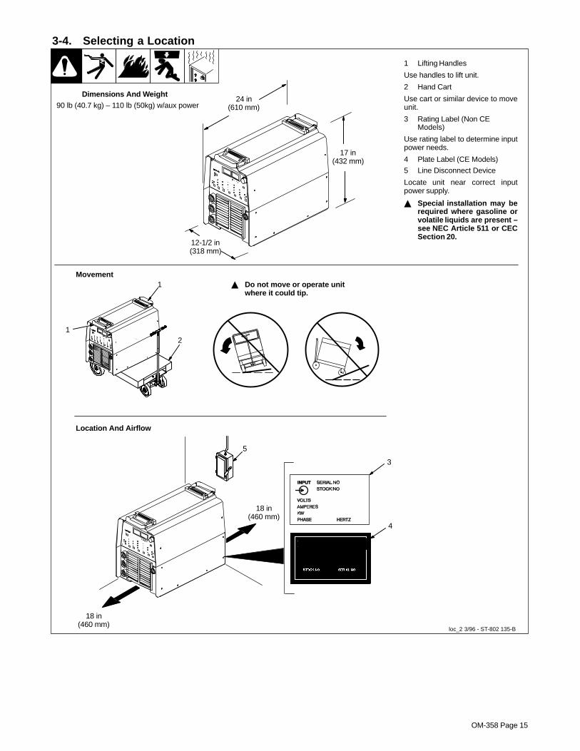
3-4. Selecting a Location
loc_2 3/96 - ST-802 135-B
1 Lifting Handles
Use handles to lift unit.
2 Hand Cart
Use cart or similar device to moveunit.
3 Rating Label (Non CEModels)
Use rating label to determine inputpower needs.
4 Plate Label (CE Models)
5 Line Disconnect Device
Locate unit near correct inputpower supply.
� Special installation may berequired where gasoline orvolatile liquids are present –see NEC Article 511 or CECSection 20.
24 in(610 mm)
17 in(432 mm)
12-1/2 in(318 mm)
Movement� Do not move or operate unit
where it could tip.
Location And Airflow
5
3
Dimensions And Weight
18 in(460 mm)
18 in(460 mm)
90 lb (40.7 kg) – 110 lb (50kg) w/aux power
2
1
4
1

OM-358 Page 16
3-5. 115 Volts AC Duplex Receptacle, Circuit Breaker CB1 (Optional), And Power Switch
ST-801 866-A
1 AC Duplex Receptacle
115 V 10 A for 230/460 volt models.115 V 7 A for 400 volt models.
2 Circuit Breaker CB1
CB1 protects duplex receptaclefrom overload.
Press button to reset breaker.
3 Power On/Off Switch
13
2
3-6. Weld Output Terminals And Selecting Cable Sizes*
� ARC WELDING can cause Electromagnetic Interference.
To reduce possible interference, keep weld cables as short as possible, close together, and down low, such as on the floor.Locate welding operation 100 meters from any sensitive electronic equipment. Be sure this welding machine is installedand grounded according to this manual. If interference still occurs, the user must take extra measures such as movingthe welding machine, using shielded cables, using line filters, or shielding the work area.
Weld Cable Size** and Total Cable (Copper) Length in Weld CircuitNot Exceeding
100 ft (30 m) or Less 150 ft(45 m)
200 ft(60 m)
250 ft(70 m)
300 ft(90 m)
350 ft(105 m)
400 ft(120 m)
Weld OutputTerminals
� Turn off power beforeconnecting to weld out-put terminals.
� Do not use worn, dam-aged, undersized, orpoorly spliced cables.
WeldingAmps***
10 – 60%DutyCycle
60 – 100%DutyCycle
10 – 100% Duty Cycle
100 4 (20) 4 (20) 4 (20) 3 (30) 2 (35) 1 (50) 1/0 (60) 1/0 (60)
150 3 (30) 3 (30) 2 (35) 1 (50) 1/0 (60) 2/0 (70) 3/0 (95) 3/0 (95)
200 3 (30) 2 (35) 1 (50) 1/0 (60) 2/0 (70) 3/0 (95) 4/0 (120) 4/0 (120)
250 2 (35) 1 (50) 1/0 (60) 2/0 (70) 3/0 (95) 4/0 (120)2 ea. 2/0(2x70)
2 ea. 2/0(2x70)
300 1 (50) 1/0 (60) 2/0 (70) 3/0 (95) 4/0 (120)2 ea. 2/0(2x70)
2 ea. 3/0(2x95)
2 ea. 3/0(2x95)
Work Electrode350 1/0 (60) 2/0 (70) 3/0 (95) 4/0 (120)
2 ea. 2/0(2x70)
2 ea. 3/0(2x95)
2 ea. 3/0(2x95)
2 ea. 4/0(2x120)
* This chart is a general guideline and may not suit all applications. If cable overheating occurs (normally you can smell it), use next size largercable.
**Weld cable size (AWG) is based on either a 4 volts or less drop or a current density of at least 300 circular mils per ampere.( ) = mm2 for metric use S-0007-E–
***Select weld cable size for pulsing application at peak amperage value.

OM-358 Page 17
3-7. Remote 14 Receptacle Information
ST-802 135-B
Socket* Socket InformationST-802 135-B
A J 24 VOLTS DC
A Contactor control, 24 volts dc.
A JB K I
C L N H
D M G
24 VOLTS DC
B Contact closure to A completes 24 volts dccontactor control circuit, and enables output.
E FC Output to remote control; 0 to +10 volts dc output
to remote control.
REMOTEOUTPUT D Remote control circuit common.
CONTROLE 0 to +10 volts dc input command signal from
remote control.
A/VF Current feedback; +1 volt dc per 100 amperes.
A/VAMPERAGEVOLTAGE
H Voltage feedback; +1 volt dc per 10 outputreceptacle volts.
GND K Chassis common.
*The remaining sockets are not used.

OM-358 Page 18
3-8. Remote Program Select Inputs (Optional For DX Models)
10-Pin Receptacle RC2
Pin Designations
0=No Connection
1=Connected To Ground (Pin G)
Function C H F E D
No Remote Control 0 0 0 X X
Stick EP Of Current Program 1 0 0 X X
Stick AC Of Current Program 1 1 0 x x
TIG AC Of Current Program 0 1 0 x x
Program 1 Stick EP 1 0 1 0 0
Program 2 Stick EP 1 0 1 0 1
Program 3 Stick EP 1 0 1 1 0
Program 4 Stick EP 1 0 1 1 1
Program 1 TIG EN 0 0 1 0 0
Program 2 TIG EN 0 0 1 0 1
Program 3 TIG EN 0 0 1 1 0
A H Program 4 TIG EN 0 0 1 1 1J
BH
G Program 1 Stick AC 1 1 1 0 0
IC
D E
FProgram 2 Stick AC 1 1 1 0 1D E
Program 3 Stick AC 1 1 1 1 0
ST-802 135-B Program 4 Stick AC 1 1 1 1 1*The remaining sockets are not used.
Program 1 TIG AC 0 1 1 0 0
Program 2 TIG AC 0 1 1 0 1
Program 3 TIG AC 0 1 1 1 0
Program 4 TIG AC 0 1 1 1 1
Socket A Contactor control, 24 volts dc
Socket B Contact closure to A, completes 24 volts dc contactor
control circuit and enables output
Socket G Chassis ground
Socket I Normally open valid arc relay
Socket J Circuit common for valid arc relay
To use the Remote Process Select function for a given program, select the TIG process on the front panel while the desired program
is selected.

OM-358 Page 19
3-9. Automation Connection (LX Models Only)
Socket Socket Information For 10-Pin Receptacle RC2
A Start/Stop
B Gas
C Output disable
D Chassis ground
E Final slope – collector
JG
F ED F Final slope – emitter
J
I
CH G Pulse lockout – collector
ST-802 135-B
A BI
H Pulse lockout – emitterST-802 135-B
I Valid arc – collector
J Valid arc – emitter
Definitions Of Inputs And Outputs
Inputs
A - Closure to D starts the weld cycle. Opening closure stops weld cycle. Durning 2T operation, a momentary closure (greater than 100ms, butless than 3/4 seconds) starts and stops weld output.
B - Closure to D turns on gas. This input will override Postflow, but if a Preflow time is entered, the Preflow cycle will time out before arc initia-tion.
C - Closure to D must be maintained at all times. If the closure between pins C and D is broken, an output disable occurs, Postflow begins totime out, and HELP 13 will be displayed on the meters.
Outputs
Outputs are isolated open-collector transistor which are able to conduct at least 6 mA of current, with a maximum of 100 mA of current and 30VDC.
OM-358 Page 20
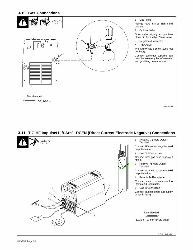
3-10. Gas Connections
ST-801 866
1 Gas Fitting
Fittings have 5/8-18 right-handthreads.
2 Cylinder Valve
Open valve slightly so gas flowblows dirt from valve. Close valve.
3 Regulator/Flowmeter
4 Flow Adjust
Typical flow rate is 15 cfh (cubic feetper hour).
Connect customer supplied gashose between regulator/flowmeterand gas fitting on rear of unit.
Tools Needed:
3 24
1
5/8, 1-1/8 in
3-11. TIG HF Impulse/ Lift-Arc� DCEN (Direct Current Electrode Negative) Connections
Ref. ST-802 680
1 Negative (–) Weld OutputTerminal
Connect TIG torch to negative weldoutput terminal.
2 Gas Out Connection
Connect torch gas hose to gas outfitting.
3 Positive (+) Weld OutputTerminal
Connect work lead to positive weldoutput terminal.
4 Remote 14 Receptacle
Connect desired remote control toRemote 14 receptacle.
5 Gas In Connection
Connect gas hose from gas supplyto gas in fitting.
Tools Needed:
2
3
4
11/16 in, (21 mm for CE units)
51

OM-358 Page 21
3-12. Front Panel Display For TIG HF Impulse DCEN (Direct Current Electrode Negative)
ST-198 708
1 Front Panel
Correct front panel display for basicTIG HF Impulse DCEN welding.
� For all front panel switch padcontrols: press switch pad toturn on light and enablefunction.
NOTE: Green on nameplate indi-cates a TIG function (see Section4-1 for description of controls).
1
ST-198 714
CE Models

OM-358 Page 22
3-13. Stick DCEP (Direct Current Electrode Positive) Connections
Ref. ST-802 650-A
1 Negative (–) Weld OutputTerminal
Connect work lead to negative weldoutput terminal.
2 Positive (+) Weld OutputTerminal
Connect electrode holder to posi-tive weld output terminal.
3 Remote 14 Receptacle
If desired, connect remote controlto Remote 14 receptacle (see Sec-tion 3-7).
1
2 3

OM-358 Page 23
3-14. Front Panel Display For Stick DCEP (Direct Current Electrode Positive)
ST-198 708
1 Front Panel
Correct front panel display for basicStick DCEP welding.
� For all front panel switch padcontrols: press switch pad toturn on light and enablefunction.
NOTE: Gray on nameplate indi-cates a Stick function (see Section4-1 for description of controls).
1
ST-198 714
CE Models

OM-358 Page 24
3-15. Electrical Service Guide
A. For Multivoltage Units
Actual input voltage cannot exceed ± 10% of indicated required input voltage. Ifactual input voltage is outside of this range, no output is available.
NOTE
Three-Phase Single-Phase
Input Voltage 230 460 230 460
AC 26.5 17.9 62.6 32.2Input Amperes At Rated Output
DC 20.5 13.4 44 25.8
Max Recommended Standard Fuse Or Circuit BreakerRating In Amperes
50 25 100 50
Min Input Conductor Size In AWG/Kcmil 10 14 8 10
Max Recommended Input Conductor Length In Feet (Meters)
104 (32) 165 (50) 90 (27) 241 (74)
Min Grounding Conductor Size In AWG/Kcmil 10 14 8 10
Reference: 1996 National Electrical Code (NEC). S-0092J
B. For Single Voltage Units
Input Voltage 400
Input Amperes At Rated Output 20.2
Max Recommended Standard Fuse Or Circuit Breaker Rating In Amperes 30
Min Input Conductor Size In AWG/Kcmil 14
Max Recommended Input Conductor Length In Feet (Meters) 125 (38)
Min Grounding Conductor Size In AWG/Kcmil 14
Reference: 1996 National Electrical Code (NEC). S-0092J

OM-358 Page 25
3-16. Connecting Input PowerCheck input voltage available atsite.
1 Input And GroundingConductors
2 Line Disconnect Device
See Section 3-15.
For three-phase opera-tion:� Always connect green or
green/yellow wire to supplygrounding terminal, never toa line terminal.
Connect black, white, and red wires(L1, L2, L3) to line terminals.
For single-phase opera-tion: 208-230/460 VoltModels� Always connect green wire
to supply grounding termi-nal, never to a line terminal.
3 Black And White InputConductor
4 Red Input Conductor
5 Insulation Sleeving
6 Electrical Tape
Insulate and isolate red conductoras shown.
1
3
1
65
4
� Always connect groundingconductor first.
= GND/PE
Green OrGreen/Yellow
Green Or
Green/Yellow
input_2 3/96 - ST-802 136-A
L1
2
1
L2
L3
3
2
1
L1L2
1
Green Or
Green/Yellow

OM-358 Page 26
SECTION 4 – OPERATION4-1. Controls
A. Non CE Units (DX/LX Model Shown)
ST-198 708 / ST-802 452
123
4 5
11
8
12
6 7
� For all front panel switch pad controls:press switch pad to turn on light and enablenormal function.
NOTE: Green on nameplate indicates a TIGfunction, Gray indicates a normal Stick function.1 Encoder ControlUse encoder control in conjunction with applica-ble front panel function switch pads to changevalues for that function. See Section 4-2.2 AmmeterSee Section 4-3.3 VoltmeterSee Section 4-3.
4 Polarity Control
See Section 4-4.
5 Process Controls
See Section 4-5.
6 Output Controls
See Section 4-7.
To reconfigure 2T control for use as 4T, 4TE, Mi-ni Logic control, or Spot control see Section4-14.
7 Pulser Controls (DX And LXModels)
See Section 4-11.
8 Sequencer Controls (DX, LX AndAll CE Models)
See Section 4-12.
9 Adjust Controls
See Section 4-9.
10 AC Waveshape
See Section 4-10.
11 Amperage Control
See Section 4-8.
12 Power Switch
Use switch to turn unit On/Off.
Rear Panel
9 10

OM-358 Page 27
B. For CE Units (DX/LX Model Shown)
ST-198 714 / ST-802 452
12
Rear Panel
123
4 5
11
86 7 9 10
� For all front panel switch pad controls:press switch pad to turn on light and enablenormal function.
NOTE: Green on nameplate indicates a TIGfunction, Gray indicates a normal Stick function.1 Encoder ControlUse encoder control in conjunction with applica-ble front panel function switch pads to changevalues for that function. See Section 4-2.2 AmmeterSee Section 4-3.3 VoltmeterSee Section 4-3.
4 Polarity Control
See Section 4-4.
5 Process Controls
See Section 4-5.
6 Output Controls
See Section 4-7.
To reconfigure 2T control for use as 4T, 4TE, Mi-ni Logic control, or Spot control see Section4-14.
7 Pulser Controls (DX And LXModels)
See Section 4-11.
8 Sequencer Controls (DX, LX And AllCE Models)
See Section 4-12.
9 Adjust Controls
See Section 4-9.
10 AC Waveshape
See Section 4-10.
11 Amperage Control
See Section 4-8.
12 Power Switch
Use switch to turn unit On/Off.

OM-358 Page 28
4-2. Encoder Control
1 Encoder Control
Use control in conjunction with ap-plicable front panel function switchpad to set values for that function.
1
4-3. Ammeter And Volt Meter
1 Volt Meter
Displays output or open circuit volt-age. If output is off, the voltmeter willdisplay a series of three dashes(-––). Open circuit voltage is dis-played if power is on and output isavailable.
2 Ammeter
Displays actual amperage whilewelding. Meter also displays presetparameters for any of the followingunits of measure when they are ac-tive: amperage, time, percentage orfrequency. The correspondingLED, located directly below the am-meter, will also illuminate.
1 2
4-4. Polarity Control
1 Polarity Control
Press switch pad until desired LEDis illuminated.
DC - Machine is set to DCEN (directcurrent electrode negative) for TIGwelding, and to DCEP (direct cur-rent electrode positive) for Stickwelding.
AC - Use AC (alternating current)for TIG and Stick welding.
CE Models Only
1
OM-358 Page 29
4-5. Process Control
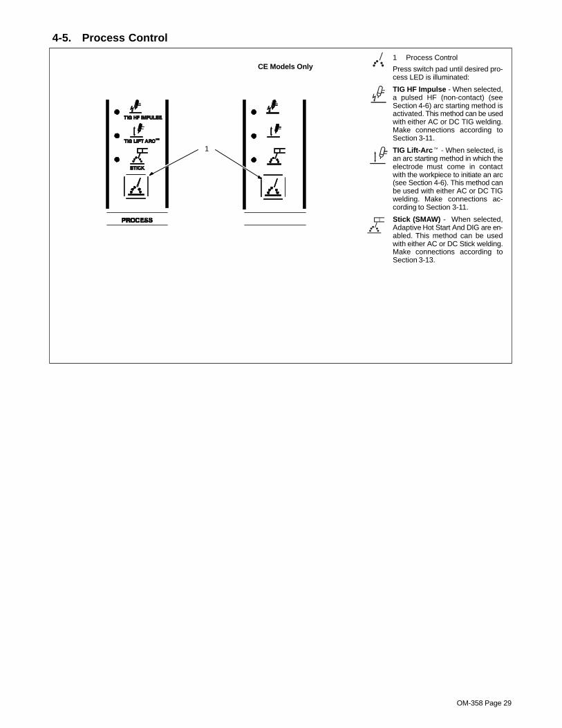
1 Process Control
Press switch pad until desired pro-cess LED is illuminated:
TIG HF Impulse - When selected,a pulsed HF (non-contact) (seeSection 4-6) arc starting method isactivated. This method can be usedwith either AC or DC TIG welding.Make connections according toSection 3-11.
TIG Lift-Arc� - When selected, isan arc starting method in which theelectrode must come in contactwith the workpiece to initiate an arc(see Section 4-6). This method canbe used with either AC or DC TIGwelding. Make connections ac-cording to Section 3-11.
Stick (SMAW) - When selected,Adaptive Hot Start And DIG are en-abled. This method can be usedwith either AC or DC Stick welding.Make connections according toSection 3-13.
1
CE Models Only

OM-358 Page 30
4-6. Lift-Arc And HF TIG Start Procedures
Lift-Arc Start
When Lift-Arc� button light is On,start arc as follows:
1 TIG Electrode
2 Workpiece
Touch tungsten electrode to work-piece at weld start point, enable out-put with torch trigger, foot control, orhand control. Hold electrode toworkpiece for 1-2 seconds, andslowly lift electrode. Shielding gasbegins to flow when electrodetouches workpiece and arc isformed when electrode is lifted.
Normal open-circuit voltage is notpresent before tungsten electrodetouches workpiece; only a lowsensing voltage is present betweenelectrode and workpiece. Thesolid-state output contactor doesnot energize until after electrode istouching workpiece. This allowselectrode to touch workpiece with-out overheating, sticking, or gettingcontaminated.
Application:
Lift-Arc is used for the DCEN or ACGTAW process when HF Startmethod is not permitted, or to re-place the scratch method.
HF Start
When HF Start button light is On,start arc as follows:
High frequency turns on to helpstart arc when output is enabled.High frequency turns off when arc isstarted, and turns on whenever arcis broken to help restart arc.
Application:
HF start is used for the DCENGTAW process when a non-con-tact arc starting method is required.
1
1 – 2Seconds“Touch”
Do NOT Strike Like A Match!
2Lift-Arc Start Method

OM-358 Page 31
Notes

OM-358 Page 32
4-7. Output Control
1
CE Models Only
Current (A)
Preflow
Initial Amps
Initial Slope Final Slope
Postflow
Weld Amps
Final Amps
Release ForMaintained Switch
Remote (Standard) Torch Trigger Operation
Release Foot OrFinger RemoteControl
Push & HoldFoot Or FingerRemote Control
NOTE: If arc is broken and trigger is depressed, HLP-10 will be displayed (see Section 5-3).
1 Output Control
Press switch pad until desired param-eter LED is illuminated.
RMT STD (Remote Standard)
Torch trigger operation is as shown.
NOTE: When a foot or finger remotecontrol is connected to the welding
power source, initial amps, initialslope, final slope, and final amps arenot functional.
NOTE: If a foot or finger control is con-nected, initial weld amperage, initialslope, final amperage, and final slopeis controlled by the remote device, notby the welding power source.
NOTE: If On/Off only type trigger isused, it must be a maintained switch.All functions become active, and mustbe set by the operator.
Application: Use Remote Triggerwhen the operator desires to use afoot pedal or finger amperage control.
OM-358 Page 33
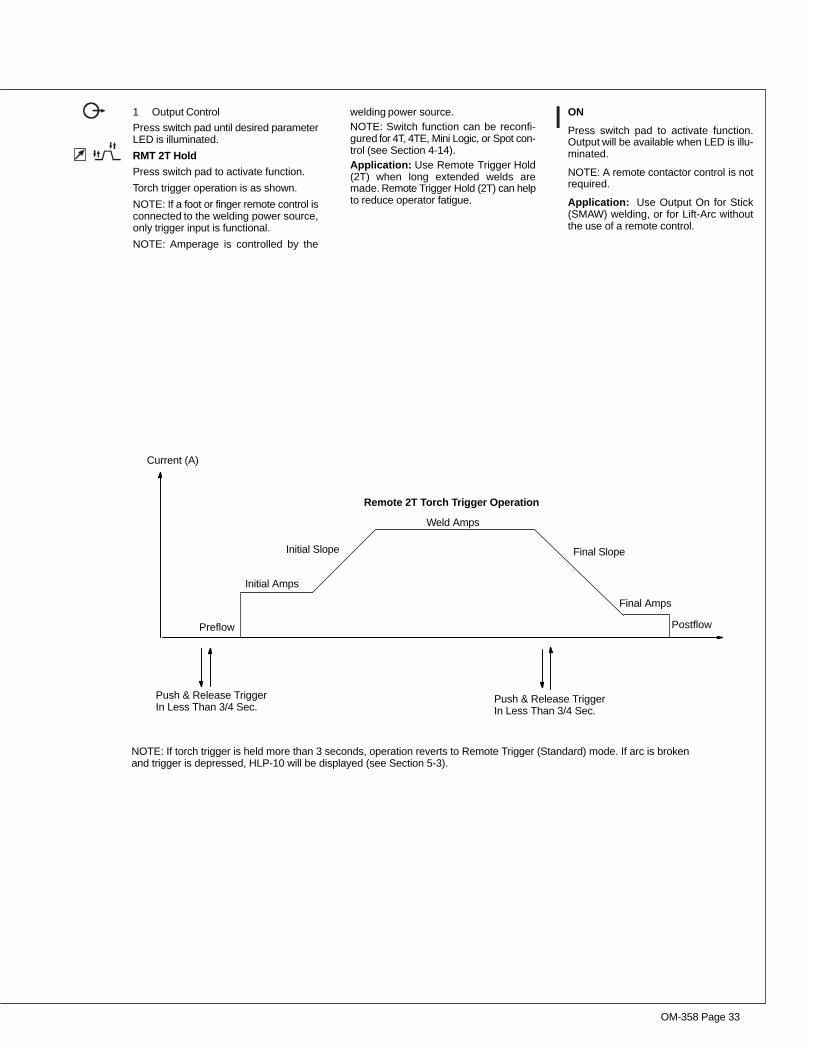
1 Output Control
Press switch pad until desired parameterLED is illuminated.
RMT 2T Hold
Press switch pad to activate function.
Torch trigger operation is as shown.
NOTE: If a foot or finger remote control isconnected to the welding power source,only trigger input is functional.
NOTE: Amperage is controlled by the
welding power source.NOTE: Switch function can be reconfi-gured for 4T, 4TE, Mini Logic, or Spot con-trol (see Section 4-14).Application: Use Remote Trigger Hold(2T) when long extended welds aremade. Remote Trigger Hold (2T) can helpto reduce operator fatigue.
ON
Press switch pad to activate function.Output will be available when LED is illu-minated.
NOTE: A remote contactor control is notrequired.
Application: Use Output On for Stick(SMAW) welding, or for Lift-Arc withoutthe use of a remote control.
NOTE: If torch trigger is held more than 3 seconds, operation reverts to Remote Trigger (Standard) mode. If arc is brokenand trigger is depressed, HLP-10 will be displayed (see Section 5-3).
Current (A)
Preflow
Initial Amps
Initial Slope Final Slope
Postflow
Push & Release TriggerIn Less Than 3/4 Sec.
Weld Amps
Final Amps
Remote 2T Torch Trigger Operation
Push & Release TriggerIn Less Than 3/4 Sec.
OM-358 Page 34
4-8. Amperage Control
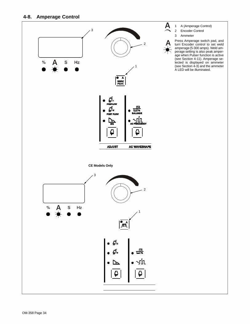
1 A (Amperage Control)
2 Encoder Control
3 Ammeter
Press Amperage switch pad, andturn Encoder control to set weldamperage (5-300 amps). Weld am-perage setting is also peak amper-age when Pulser function is active(see Section 4-11). Amperage se-lected is displayed on ammeter(see Section 4-3) and the ammeterA LED will be illuminated.
1
2
3
1
2
3
CE Models Only

OM-358 Page 35
4-9. Adjust Controls (Post Flow/DIG)
1 Preflow/Post Flow/DIGControl
Press switch pad until desired func-tion LED is illuminated.
2 Encoder Control
3 Ammeter
Preflow - If the TIG process is ac-tive (see Section 4-5), press switchpad and turn encoder control to setlength of time (0–15 seconds) gasflows before arc initiation.
Application: Preflow is used topurge the immediate weld area ofatmosphere. Preflow also aids inconsistent arc starts.
Post Flow - This switch activates aprocess specific function. If the TIGprocess is active (see Section 4-5),press switch pad and turn encodercontrol to set length of time (0–50seconds) gas flows after weldingstops. Time selected is displayedon ammeter (see Section 4-3) andthe ammeter S LED will be illumi-nated.
Application:
Postflow is required to cool tung-sten and weld, and to prevent con-tamination of tungsten and weld. In-crease postflow time if tungsten orweld are dark in appearance.
DIG - If the Stick process is active(see Section 4-5), press switch padand turn encoder control to setamount of DIG (0-100%). When setat 0, short-circuit amperage at lowarc voltage is the same as normalwelding amperage.
When setting is increased, short-circuit amperage at low arc voltageincreases.
Percentage selected is displayedon ammeter (see Section 4-3) andthe ammeter % LED will be illumi-nated.
Application:
Control helps arc starting or makingvertical or overhead welds by in-creasing amperage at low arc volt-age, and reduces electrode stickingwhile welding.
1
2
3
1
2
3
CE Models Only

OM-358 Page 36
4-10. AC Wave Shape
1 Balance And AC FrequencyControl
2 Encoder Control
3 Ammeter
Balance: Press switch pad andturn Encoder Control to set per-centage of time, 50–90%, polarity iselectrode negative. AC BalanceControl is enabled only if AC TIGprocess is selected.
Application:
When welding on oxide forming ma-terials such as aluminum or magne-sium, excess cleaning is not neces-sary. To produce a good weld, onlya minimal amount, approximately a0.10 in (2.5mm) of etched zonealong the weld toes is required.
Joint configuration, set-up, processvariables, and oxide thickness mayaffect setting.
Arc rectification can occur whenwelding above 200 amps and/orwhile welding with helium gas. If thiscondition occurs, increasing theBalance control towards maximumpenetration, may help to restabilizethe arc.
AC Frequency: Press switch padand turn Encoder Control to set ACfrequency from 20–250 Hz (cyclesper second). AC Frequency Con-trol is enabled only if AC TIG pro-cess is selected.
Application:
AC frequency controls bead widthand directional control. As AC fre-quency decreases, weld bead/puddle gets wider. As AC frequencyincreases, weld bead/puddle be-comes narrower and the arc be-comes more focused. Travel speedcan increase as AC frequency in-creases.
1
2
3
1
2
3
CE Models Only

OM-358 Page 37
1 Pulser Control
Press switch pad to enable pulser.
Press switch pad until desired pa-rameter LED is illuminated. Pulsingis available only while using the TIGprocess, it cannot be selected if theStick process (see Section 4-5) isactive. Controls can be adjustedwhile welding.
2 Encoder Control
3 Ammeter
Turn encoder (see Section 4-2) toselect appropriate value for activepulse parameter. Value selected isshown on the ammeter (see Sec-tion 4-3). Also, the ammeter LED forthe corresponding unit of measure(%, A, s, Hz) of the active parame-ter will be illuminated.
Pulser parameters are as follows:
On - When illuminated, this LED in-dicates the pulser is on.
PPS (Pulse Frequency) - Rangesfrom .1–500 pps (pulses per sec-ond). Control is used to determineappearance of weld bead.
Peak Time - A range of 5–95% ofeach pulse cycle can be spent atthe peak amperage level.
BKGND A (Background Amps) -Use Background Amps control toset the low pulse of the weld amper-age, which cools the weld puddleand affects overall heat input. Back-ground Amps is set as a percent-age (5-95%) of peak amperage.
4 Pulsed Output Waveforms
Example shows affect changing thePeak Time control has on thepulsed output waveform.
NOTE: Peak amperage is set usingthe Amperage control (see Section4-8). Peak amperage (5–300amps) is the highest welding am-perage allowed to occur in the pulsecycle. Weld penetration varies di-rectly with peak amperage.
Application:
Pulsing refers to the alternatingraising and lowering of the weld out-put at a specific rate. The raisedportions of the weld output are con-trolled in width, height, and frequen-cy, forming pulses of weld output.These pulses and the lower amper-age level between them (called thebackground amperage) alternatelyheat and cool the molten weldpuddle. The combined effect givesthe operator better control of pene-tration, bead width, crowning, un-dercutting, and heat input. Controlscan be adjusted while welding.
Pulsing can also be used for fillermaterial addition techniquetraining.
4-11. Pulser Control (DX And LX Models)
1
3
2
Peak Amp
Bkg AmpBalanced
More TimeAt Peak
Amperage
More Time AtBackgroundAmperage
Pulsed Output WaveformsPercent (%) PeakTime Control Setting
(50%)
(80%)
(20%)
PPS
4
CE Models Only

OM-358 Page 38
4-12. Sequencer Controls (DX, LX And All CE Models)
1
2
3
2
3
1
CE Models Only
1 Sequencer Control
Press switch pad until desired pa-rameter LED is illuminated. Se-quencing is available only while us-ing the TIG process, but is disabledif a remote foot or finger control isconnected to the Remote recep-tacle (see Section 3-7). Sequencerparameters cannot be selected ifthe Stick process (see Section 4-5)is active.
2 Encoder Control
3 Ammeter
Turn encoder (see Section 4-2) toset appropriate value for active se-quence parameter. Value selectedis shown on the ammeter (see Sec-tion 4-3). Also, the ammeter LED forthe corresponding unit of measure(A, s) of the active parameter will beilluminated.
4 Amperage Control
Weld Time (LX Models Only) -Press Amperage switch pad twice.Set weld time from 0 to 999 sec-onds.
The Sequencer parameters are asfollows:
Initial A (Initial Amperage) - Usecontrol to select a starting amper-age (1–300 amps) that is differentfrom the weld amperage.
Application:
Initial Amperage can be used whileGTAW welding to assist in preheat-ing cold material prior to depositingfiller material, or to ensure a softstart.
Initial t (Initial Time)(LX ModelsOnly) - Press control again to se-lect 0-25 seconds of time that isneeded at the beginning of the weld.
Initial Slope t (Initial Slope Time)Use control to select 0-25 secondsof time that it takes to slope up/down from initial amperage to weldamperage. To disable, set to 0.
Final Slope t (Final Slope Time) -Use control to select 0-25 secondsof time that it takes to slope up/down from weld amperage to finalamperage. To disable, set to 0.
Application:
Final Slope should be used whileGTAW welding materials that arecrack sensitive, and/or the operatorwants to eliminate the crater at theend of the weld.
Final A (Final Amperage) - Finalamperage (1-300 amps) is the am-perage to which weld amperagehas sloped up/down to.
Final t (Final Time)(LX ModelsOnly) - Press control again to se-lect 0-25 seconds of time that isneeded at the end of the weld.
4
4

OM-358 Page 39
Notes
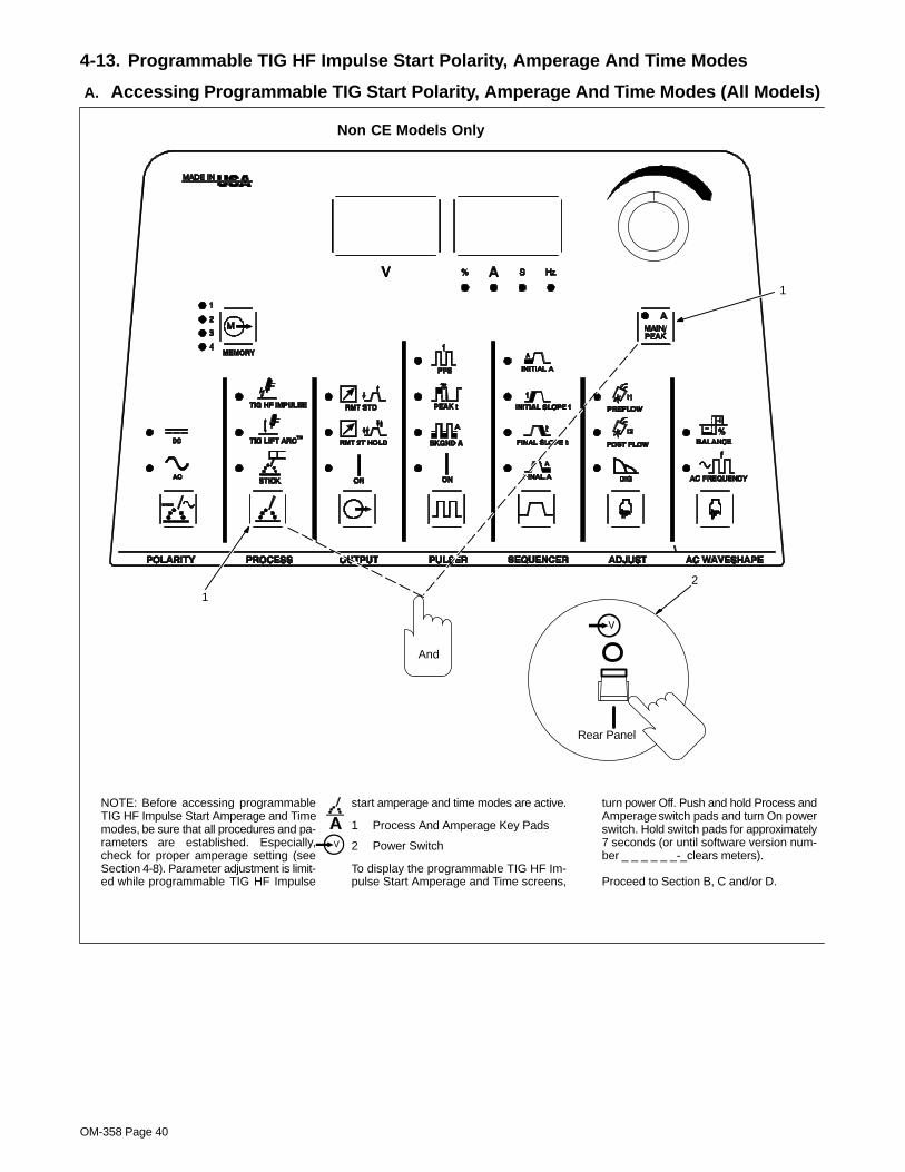
OM-358 Page 40
4-13. Programmable TIG HF Impulse Start Polarity, Amperage And Time Modes
A. Accessing Programmable TIG Start Polarity, Amperage And Time Modes (All Models)
NOTE: Before accessing programmableTIG HF Impulse Start Amperage and Timemodes, be sure that all procedures and pa-rameters are established. Especially,check for proper amperage setting (seeSection 4-8). Parameter adjustment is limit-ed while programmable TIG HF Impulse
start amperage and time modes are active.
1 Process And Amperage Key Pads
2 Power Switch
To display the programmable TIG HF Im-pulse Start Amperage and Time screens,
turn power Off. Push and hold Process andAmperage switch pads and turn On powerswitch. Hold switch pads for approximately7 seconds (or until software version num-ber _ _ _ _ _ _-_clears meters).
Proceed to Section B, C and/or D.
Rear Panel
2
1
1
And
Non CE Models Only

OM-358 Page 41
CE Models Only
NOTE: Before accessing programmableTIG HF Impulse Start Amperage and Timemodes, be sure that all procedures and pa-rameters are established. Especially,check for proper amperage setting (seeSection 4-8). Parameter adjustment is limit-ed while programmable TIG HF Impulse
start amperage and time modes are active.
1 Process And Amperage Key Pads
2 Power Switch
To display the programmable TIG HF Im-pulse Start Amperage and Time screens,
turn Off power. Push and hold Process andAmperage switch pads and turn On powerswitch. Hold switch pads for approximately7 seconds (or until software version num-ber _ _ _ _ _ _-_clears meters).
Proceed to Section B, C and/or D.
Rear Panel
2
1
1
And
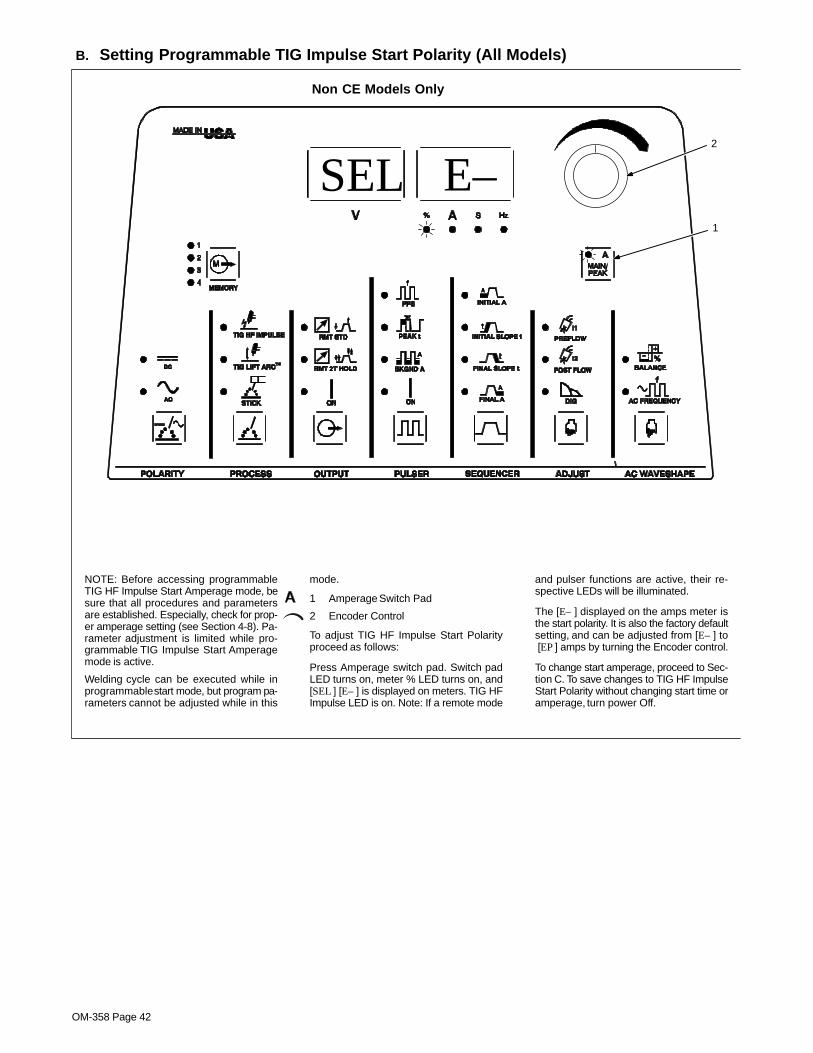
OM-358 Page 42
B. Setting Programmable TIG Impulse Start Polarity (All Models)
NOTE: Before accessing programmableTIG HF Impulse Start Amperage mode, besure that all procedures and parametersare established. Especially, check for prop-er amperage setting (see Section 4-8). Pa-rameter adjustment is limited while pro-grammable TIG Impulse Start Amperagemode is active.
Welding cycle can be executed while inprogrammable start mode, but program pa-rameters cannot be adjusted while in this
mode.
1 Amperage Switch Pad
2 Encoder Control
To adjust TIG HF Impulse Start Polarityproceed as follows:
Press Amperage switch pad. Switch padLED turns on, meter % LED turns on, and[SEL ] [E– ] is displayed on meters. TIG HFImpulse LED is on. Note: If a remote mode
and pulser functions are active, their re-spective LEDs will be illuminated.
The [E– ] displayed on the amps meter isthe start polarity. It is also the factory defaultsetting, and can be adjusted from [E– ] to [EP ] amps by turning the Encoder control.
To change start amperage, proceed to Sec-tion C. To save changes to TIG HF ImpulseStart Polarity without changing start time oramperage, turn power Off.
Non CE Models Only
1
2
SEL E–

OM-358 Page 43
CE Models Only
1
SEL E–2
NOTE: Before accessing programmableTIG HF Impulse Start Amperage mode, besure that all procedures and parametersare established. Especially, check for prop-er amperage setting (see Section 4-8). Pa-rameter adjustment is limited while pro-grammable TIG Impulse Start Amperagemode is active.
Welding cycle can be executed while inprogrammable start mode, but program pa-rameters cannot be adjusted while in this
mode.
1 Amperage Switch Pad
2 Encoder Control
To adjust TIG HF Impulse Start Polarityproceed as follows:
Press Amperage switch pad. Switch padLED turns on, meter % LED turns on, and[SEL ] [E– ] is displayed on meters. TIG HFImpulse LED is on. Note: If a remote mode
and pulser functions are active, their re-spective LEDs will be illuminated.
The [E– ] displayed on the amps meter isthe start polarity. It is also the factory defaultsetting, and can be adjusted from [E– ] to [EP ] amps by turning the Encoder control.
To change start amperage, proceed to Sec-tion C. To save changes to TIG HF ImpulseStart Polarity without changing start time oramperage, turn power Off.

OM-358 Page 44
C. Setting Programmable TIG Impulse Start Amperage (All Models)
NOTE: Before accessing programmableTIG HF Impulse Start Amperage mode, besure that all procedures and parametersare established. Especially, check for prop-er amperage setting (see Section 4-8). Pa-rameter adjustment is limited while pro-grammable TIG Impulse Start Amperagemode is active.
Welding cycle can be executed while inprogrammable start mode, but program pa-rameters cannot be adjusted while in this
mode.
1 Amperage Switch Pad
2 Encoder Control
To adjust TIG HF Impulse Start Polarityproceed as follows:
Press Amperage switch pad. Switch padLED turns on, meter A LED turns on, and[SEL ] [20 ] is displayed on meters. TIG HFImpulse LED is on. Note: If a remote mode
and pulser functions are active, their re-spective LEDs will be illuminated.The [20 ] displayed on the amps meter is ACstart amps (it is also the factory default set-ting – [30 ] for DC start amps), and can beadjusted from 1 to 200 amps by turning theEncoder control.To change start amps, proceed to SectionD. To save changes to TIG HF ImpulseStart Amperage without changing starttime, turn power Off.
Non CE Models Only
1
2
SEL 20

OM-358 Page 45
CE Models Only
1
SEL 202
NOTE: Before accessing programmableTIG HF Impulse Start Amperage mode, besure that all procedures and parametersare established. Especially, check for prop-er amperage setting (see Section 4-8). Pa-rameter adjustment is limited while pro-grammable TIG Impulse Start Amperagemode is active.
Welding cycle can be executed while inprogrammable start mode, but program pa-rameters cannot be adjusted while in this
mode.
1 Amperage Switch Pad
2 Encoder Control
To adjust TIG HF Impulse Start Polarityproceed as follows:
Press Amperage switch pad. Switch padLED turns on, meter A LED turns on, and[SEL ] [20 ] is displayed on meters. TIG HFImpulse LED is on. Note: If a remote mode
and pulser functions are active, their re-spective LEDs will be illuminated.The [20 ] displayed on the amps meter is ACstart amps (it is also the factory default set-ting – [30 ] for DC start amps), and can beadjusted from 1 to 200 amps by turning theEncoder control.To change start amps, proceed to SectionD. To save changes to TIG HF ImpulseStart Amperage without changing starttime, turn power Off.

OM-358 Page 46
D. Setting Programmable Start Time (All Models)
NOTE: Before accessing programmablestart time mode, be sure that all proceduresand parameters are established. Especial-ly, check for proper amperage setting (seeSection 4-8). Parameter adjustment is limit-ed while Programmable Start Time mode isactive.
Welding cycle can be executed while inprogrammable start mode, but program pa-
rameters cannot be adjusted while in thismode.
1 Amperage Switch Pad
2 Encoder Control
To adjust Programmable Start Time pro-ceed as follows:
Press Amperage switch pad. Switch padLED turns on, meter S LED turns on, and[SEL] [10 ] is displayed on meters.The [10 ] displayed on the amps meter is thefactory default AC setting ([SEL] [3 ] is thefactory default DC setting), and can be ad-justed from 1 to 200 milliseconds by turningthe Encoder control.To save changes, turn power Off.
Non CE Models Only
1
2
SEL 10

OM-358 Page 47
CE Models Only
NOTE: Before accessing programmablestart time mode, be sure that all proceduresand parameters are established. Especial-ly, check for proper amperage setting (seeSection 4-8). Parameter adjustment is limit-ed while Programmable Start Time mode isactive.
Welding cycle can be executed while inprogrammable start mode, but program pa-
rameters cannot be adjusted while in thismode.
1 Amperage Switch Pad
2 Encoder Control
To adjust Programmable Start Time pro-ceed as follows:
Press Amperage switch pad. Switch padLED turns on, meter S LED turns on, and[SEL] [10 ] is displayed on meters.The [10 ] displayed on the amps meter is thefactory default AC setting ([SEL] [3 ] is thefactory default DC setting), and can be ad-justed from 1 to 200 milliseconds by turningthe Encoder control.To save changes, turn power Off.
1
SEL 102
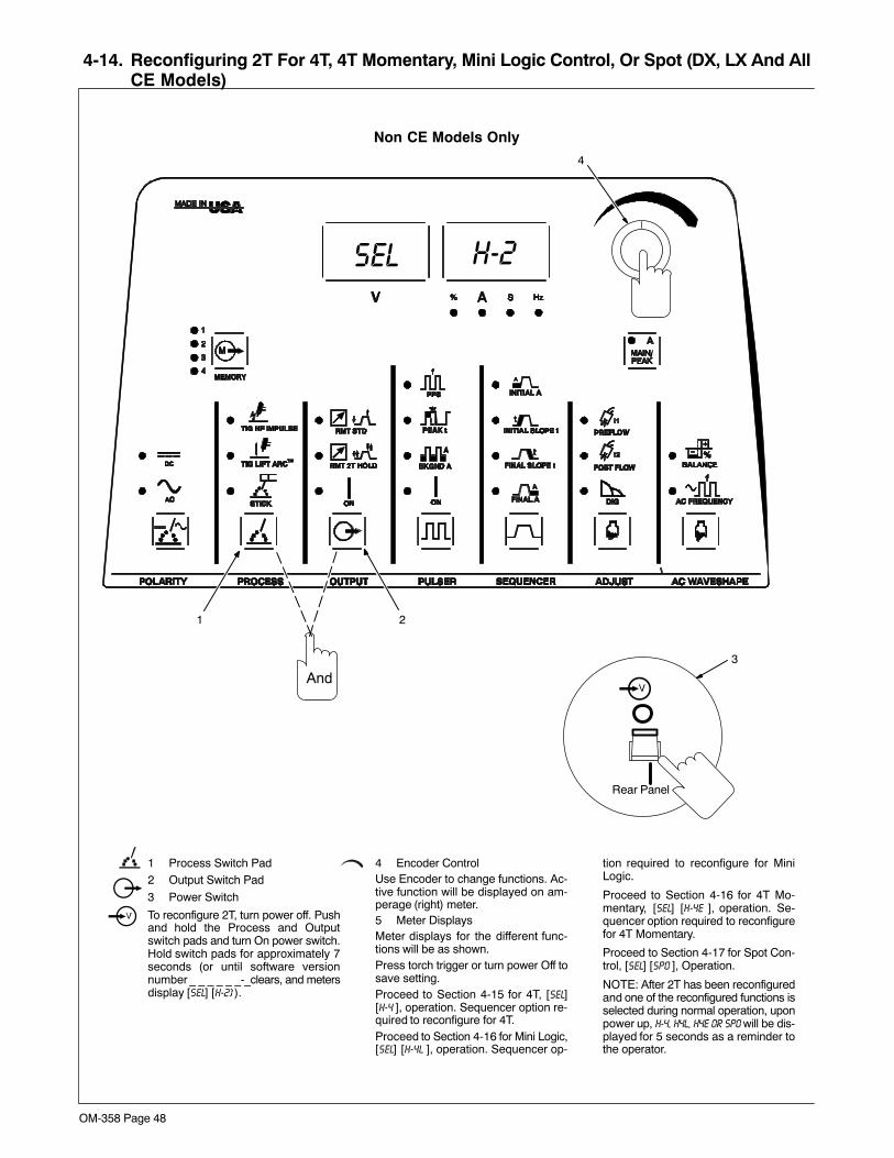
OM-358 Page 48
4-14. Reconfiguring 2T For 4T, 4T Momentary, Mini Logic Control, Or Spot (DX, LX And AllCE Models)
1 Process Switch Pad2 Output Switch Pad
3 Power Switch
To reconfigure 2T, turn power off. Pushand hold the Process and Outputswitch pads and turn On power switch.Hold switch pads for approximately 7seconds (or until software versionnumber _ _ _ _ _ _-_clears, and metersdisplay [SEL] [H-2] ).
4 Encoder ControlUse Encoder to change functions. Ac-tive function will be displayed on am-perage (right) meter.5 Meter DisplaysMeter displays for the different func-tions will be as shown.Press torch trigger or turn power Off tosave setting.Proceed to Section 4-15 for 4T, [SEL][H-4 ], operation. Sequencer option re-quired to reconfigure for 4T.Proceed to Section 4-16 for Mini Logic,[SEL] [H-4L ], operation. Sequencer op-
tion required to reconfigure for MiniLogic.
Proceed to Section 4-16 for 4T Mo-mentary, [SEL] [H-4E ], operation. Se-quencer option required to reconfigurefor 4T Momentary.
Proceed to Section 4-17 for Spot Con-trol, [SEL] [SPO ], Operation.
NOTE: After 2T has been reconfiguredand one of the reconfigured functions isselected during normal operation, uponpower up, H-4, H4L, H4E or SPO will be dis-played for 5 seconds as a reminder tothe operator.
2
4
H-2SEL
Non CE Models Only
1
And
Rear Panel
3

OM-358 Page 49
SEL H–2 =
=
=
=
2T (See Section 4-7
Mini Logic (See Section 4-16
Spot (See Section 4-17
4
SEL H–4
SEL H4L
SEL SPO
4T (See Section 4-15
=SEL H4E 4T Momentary
(See Section 4-16
for operation)
for operation)
for operation)
for operation)
for operation)

OM-358 Page 50
Reconfiguring 2T For 4T, 4T Momentary, Mini Logic Control, Or Spot (DX, LX And All CEModels) (Continued)
1 Process Switch Pad
2 Output Switch Pad
3 Power Switch
To reconfigure 2T, turn power off. Pushand hold the Process and Outputswitch pads and turn On power switch.Hold switch pads for approximately 7seconds (or until software versionnumber _ _ _ _ _ _-_clears, and metersdisplay [SEL] [H-2] ).
4 Encoder ControlUse Encoder to change functions. Ac-tive function will be displayed on am-perage (right) meter.5 Meter DisplaysMeter displays for the different func-tions will be as shown.
Press torch trigger or turn power Off tosave setting.
Proceed to Section NO TAG for 4T,[SEL] [H-4 ], operation. Sequencer optionrequired to reconfigure for 4T.Proceed to Section NO TAG for MiniLogic, [SEL] [H-4L ], operation. Sequenc-
er option required to reconfigure forMini Logic.
Proceed to Section NO TAG for 4T Mo-mentary, [SEL] [H-4E ], operation. Se-quencer option required to reconfigurefor 4T Momentary.
Proceed to Section NO TAG for SpotControl, [SEL] [SPO ], Operation.
NOTE: After 2T has been reconfiguredand the 2T LED is on, of the reconfi-gured functions is selected during nor-mal operation, upon power up, H-4, H4L,
H4E or SPO will be displayed for 5 sec-onds as a reminder to the operator.
2
4
SEL H-2
CE Models Only
1
And
Rear Panel
3
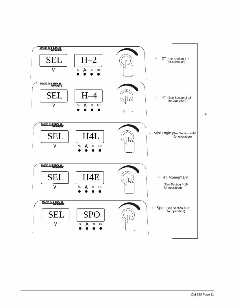
OM-358 Page 51
SEL H–2 =
=
=
=
2T
Mini Logic (See Section 4-16
Spot (See Section 4-17
4
SEL H–4
SEL H4L
SEL SPO
4T (See Section 4-15
=SEL H4E 4T Momentary
(See Section 4-16
(See Section 4-7for operation)
for operation)
for operation)
for operation)
for operation)
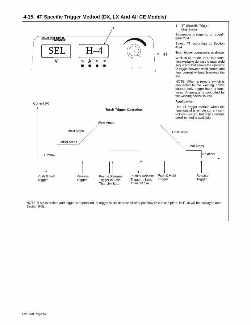
OM-358 Page 52
4-15. 4T Specific Trigger Method (DX, LX And All CE Models)
1 4T (Specific TriggerOperation)
Sequencer is required to reconfi-gure for 4T.
Select 4T according to Section4-14.
Torch trigger operation is as shown.
While in 4T mode, there is a func-tion available during the main weldsequence that allows the operatorto toggle between weld current andfinal current without breaking thearc.
NOTE: When a remote switch isconnected to the welding powersource, only trigger input is func-tional. Amperage is controlled bythe welding power source.
Application:
Use 4T trigger method when thefunctions of a remote current con-trol are desired, but only a remoteon/off control is available.
=SEL H–4 4T
Current (A)
Preflow
Initial Amps
Initial Slope Final Slope
Postflow
Push & HoldTrigger
ReleaseTrigger
Push & HoldTrigger
ReleaseTrigger
Push & ReleaseTrigger In LessThan 3/4 Sec.
Weld Amps
Final Amps
Torch Trigger Operation
Push & ReleaseTrigger In LessThan 3/4 Sec.
1
NOTE: If arc is broken and trigger is depressed, or trigger is still depressed after postflow time is complete, HLP-10 will be displayed (seeSection 5-3).

OM-358 Page 53
4-16. Mini Logic Operation (DX, LX And All CE Models)
1 Mini Logic Meter Display
Sequencer option required to re-configure for Mini Logic.
Select Mini Logic according to Sec-tion 4-14.
Torch trigger operation is as shown.
During Mini Logic welding opera-tion, the weld current can betoggled between the initial ampslevel and the main weld amps levelby pressing and releasing the torchtrigger in less than 3/4 seconds.
During Mini Logic, Final Amperageis not available. Final slope will al-ways slope to minimum amperageand end the cycle.
NOTE: When a remote switch isconnected to the welding powersource, only trigger input is func-tional. Amperage is controlled bythe welding power source.
Application: This ability to changecurrent levels without either initialslope or final slope, gives the oper-ator the opportunity to adjust fillermetal without breaking the arc.
=SEL H4L Mini Logic
1
Preflow
Initial Amps
Initial Slope Final Slope
Postflow
Weld Amps
Push & HoldTrigger For MoreThan 3/4 Sec.
Torch Trigger Operation
Release Trigger
Final SlopeRate
Push & ReleaseTrigger In LessThan 3/4 Sec.
Final SlopeRate
Initial Amps
Push & ReleaseTrigger In LessThan 3/4 Sec.
Push & HoldTrigger For MoreThan 3/4 Sec.
Push & ReleaseTrigger In LessThan 3/4 Sec.
Push & ReleaseTrigger In LessThan 3/4 Sec.
Push & HoldTrigger For MoreThan 3/4 Sec.
Push & HoldTrigger
Push & ReleaseTrigger In LessThan 3/4 Sec.
NOTE: If arc is broken and trigger is depressed, or trigger is still depressed after postflow time is complete, HLP-10 will be displayed (seeSection 5-3).

OM-358 Page 54
4-17. Spot Control Operation (All Models)
1 Spot Function Meter Display
Select Spot function according toSection 4-14.
2 Amperage Switch Pad
3 Encoder Control
Set spot parameters as follows:Press Amperage switch pad once(meter A LED turns on) and turn En-coder to set spot amperage. PressAmperage switch pad again, (meterS LED lights) and turn Encoder toset spot time (.1–25 seconds). Fac-tory default setting is 1 second.
NOTE: While in Spot Control, Se-quencer settings will be ignored,and will not be programmable.
NOTE: While in Spot Control, whena remote switch is connected to thewelding power source, only triggerinput is functional. Amperage iscontrolled by the welding powersource.
Torch trigger operation is as shown.
Application: To provide a timedweld. Used for tacking, and thinsheet joining.
=SEL SPO Spot
1 3
2
Current (A)
Preflow Postflow
Timed Spot Weld Amps
Push & HoldTrigger
NOTE: If arc is broken and trigger is depressed, or trigger is still depressed after postflow time is complete, HLP-10 will bedisplayed (see Section 5-3).
CE Models
Non CE Models
Or

OM-358 Page 55
4-18. 4T Momentary Operation (DX, LX And All CE Models)
1 4T Momentary MeterDisplay
Select 4T Momentary accordingto Section 4-14.
If unit is equipped with SequenceControls, a 4T Momentary trig-ger method is available.
4T Momentary torch trigger op-eration is as shown.
While in 4T Momentary mode,once the operator toggles out ofweld current and begins finalslope, toggling again will breakthe arc and go to postflow.
NOTE: When a remote switch isconnected to the welding powersource, only trigger input is func-tional. Amperage is controlled bythe welding power source.
Application:
Use 4T Momentary trigger meth-od when the functions of a re-mote current control are desired,but only a remote on/off control isavailable.
Select 4T Momentary triggermethod according to Section4-14.
=SEL H4E 4T Momentary
Current (A)
Preflow
Initial Amps
Initial Slope Final Slope
Postflow
Push & ReleaseTrigger In LessThan 3/4 Sec.
Push & ReleaseTrigger In LessThan 3/4 Sec.
Weld Amps
Final Amps
Push & ReleaseTrigger In LessThan 3/4 Sec.
1
Push & ReleaseTrigger In LessThan 3/4 Sec.

OM-358 Page 56
4-19. Arc Timer/Counter Display (All Models)
1 Output And Amperage Controls
2 Power Switch
To display the arc timer/counter, turn pow-er off. Push and hold Output and Amper-age control switch pads, and turn OnPower switch. Hold switch pads forapproximately 7 seconds (or until soft-ware version number _ _ _ _ _ _-_clears meters).
3 Arc Timer DisplayUpon power up as described above, themeter S LED will turn on, and arc time willbe displayed for 5 seconds as [000 000 ]to [999 999 ]. The first four numbers indi-cate hours, and the last two numbers indi-cate minutes. Arc time shown in exampleis read as 1,234 hours and 56 minutes.Maximum arc time is 9,999 hours and 59minutes.
4 Arc Counter
After 5 seconds, the meter A LED turnson, and the arc counter will be displayedfor the next 5 seconds as [000 000 ] to [999999 ]. The maximum arc cycle count is 999999.
Rear Panel
2V
And
1
Non CE Models
1
123 456
3/4
Or

OM-358 Page 57
1 Output And Amperage Controls
2 Power Switch
To display the arc timer/counter, turnpower off. Push and hold Output and Am-perage control switch pads, and turn OnPower switch. Hold switch pads forapproximately 7 seconds (or until soft-ware version number _ _ _ _ _ _-_clears meters).
3 Arc Timer DisplayUpon power up as described above, themeter S LED will turn on, and arc time willbe displayed for 5 seconds as [000 000 ]to [999 999 ]. The first four numbers indi-cate hours, and the last two numbers indi-cate minutes. Arc time shown in exampleis read as 1,234 hours and 56 minutes.Maximum arc time is 9,999 hours and 59minutes.
4 Arc Counter
After 5 seconds, the meter A LED turnson, and the arc counter will be displayedfor the next 5 seconds as [000 000 ] to [999999 ]. The maximum arc cycle count is999 999.
And
1
1
CE Models
123
456
3/4
Rear Panel
2V
Or

OM-358 Page 58
4-20. Lockout Functions
A. Accessing Lockout Capability
See Section 4-1 for explanation of controls referred to in all ofSection 4-20.
There are four (1–4) different lockout levels. Each successive levelallows the operator more flexibility.
NOTE: Before activating lockout levels, be sure that all proceduresand parameters are established. Parameter adjustment is limitedwhile lockout levels are active.
NOTE: If lockout feature is active, upon power up, after software ver-sion number clears meter displays, the amperage (right) meter willdisplay the active lockout level [LL1 ] or 2, 3, 4..1 Amperage (A) Switch Pad2 Adjust Switch Pad3 Power SwitchTo access lockout screens, press and hold the Amperage and Adjustswitch pads, and turn On power switch. Hold switch pads for approxi-mately 7 seconds (or until software version number _ _ _ _ __-_clears meters).4 Lockout OffUpon power up as described, the meter % and Amperage (A) switchpad LED’s light, and the meter display will be as shown for a lockoutoff condition.5 Encoder ControlTo turn On the lockout feature, proceed as follows:Pressing Amperage (A) switch pad will toggle between the meter %and S LED’s. Toggle switch pad until % LED is on.
Turn Encoder control to select a three digit lockout number. Numberwill appear on the voltage (left) meter. Select any number from [001]thru [999 ]. IMPORTANT: remember this three digit number, as youwill need it to turn the lockout feature off.
Toggle Amperage (A) switch pad to light the meter S LED. You maynow select a lockout level.
There are four lockout levels available. Turn Encoder control to ac-cess a lockout level (see Sections B and/or C for lockout level de-scriptions).6 Lockout OnOnce the desired three digits have been entered and a lockout levelselected, the meter screens will change to [000 [LL1 ] or 2, 3, 4.
Press torch trigger or turn Off power to complete lockout onsequence.
NOTE: Setting a three digit lockout number of [000], or setting a lock-out level of [L––] will cause a lockout off condition.
To turn Off the lockout feature, proceed as follows:To access lockout screens, press and hold the Amperage (A) andAdjust switch pads, and turn On power switch. Hold switch pads forapproximately 7 seconds (or until software version number _ _ _ _ _ _-_clears meters).
Upon power up as described, the meter % and Amperage (A) switchpad LED’s will turn on, and the meter display will be as shown for alockout on (see callout 6) condition.
Use Encoder control to enter the same three digits that were usedto turn on the lockout feature.
Press the Amperage (A) switch pad. The meter % LED will turn off,and the % and S LED’s will light. The amperage (right) meter displaywill change to [L––]. The lockout feature is now off.
NOTE: Setting a three digit lockout number of [000 ], or setting a lock-out level of [L––] will also cause a lockout off condition.
Press torch trigger or turn Off power to complete lock out Offsequence.
Rear Panel
3
1
L–0L – –
4
6
000
or 2,3,4
2
5
L–0L L1000And

OM-358 Page 59
B. LockOut Levels
Level 1
NOTE: Before activating lock outlevels, be sure that all proceduresand parameters are established.Parameter adjustment is limitedwhile lock out levels are active.
NOTE: Remote amperage controlis not available in level 1.
TIG Output Selection
If either the TIG Impulse HF or TIGLift Arc process (see Section 4-7)was active when lockout level 1was activated, the operator canchoose between RMT STD (Re-mote Standard) or RMT 2T HOLD(Remote 2T Hold). The On functionis also available if TIG Lift Arc wasactive.
If RMT 2T was reconfigured (seeSection 4-14) prior to lockout level1 activation, the reconfigured out-put mode (4T, 4T momentary, minilogic, or spot) is available to the op-erator instead of RMT 2T.
Stick Output Selection
If the Stick process was activewhen lockout level 1 was activated,the operator can choose betweenRMT STD or On.
Process selection may not bechanged in lockout level 1. If the op-erator tries to change his processselection, the amperage (right) me-ter will display [LL! ] as a reminder.
The parameters for the remainingfunctions may be viewed by press-ing the appropriate switch pads, butif unit is equipped with a pulser andthe pulser is off, [LL1] will be dis-played as a reminder that the pulseris off.
Level 2
NOTE: Before activating lockoutlevels, be sure that all proceduresand parameters are established.Parameter adjustment is limitedwhile lockout levels are active.
NOTE: Remote amperage controlis not available in level 2.
Includes all the functions of level 1plus Process Selection (see Sec-tion 4-5).
The parameters for the remainingfunctions may be viewed by press-ing the appropriate switch pads, butif unit is equipped with a pulser andthe pulser is off, [LL2 ] will be dis-played as a reminder that the pulseris off.
For The Stick Process
Process Selection
Level 1
Level 2
Use Output Switch Pad To
Select A Trigger Method
For The TIG Process
Select Stick, Or Lift-Arc, Or HF Start
Use Output Switch Pad To
Select A Trigger Method

OM-358 Page 60
C. Lock Out Levels (Continued)
Level 3
+/– 10 % Amperage Adjust Control
Select Stick Or TIG
Level 4
Remote Amperage Control
Level 3
NOTE: Before activating lockoutlevels, be sure that all proceduresand parameters are established. Pa-rameter adjustment is limited whilelockout levels are active.
NOTE: Remote amperage control isnot available in level 3.
Includes all the functions of levels 1and 2 plus the following:
+/– 10% adjustment of preset TIGor Stick Weld Amps
Select desired process, TIG orStick, and use Encoder control toadjust amperage +/– 10% of presetamperage value, up to the limits ofthe machine. If operator tries to gobeyond the +/– 10%, the amperage(right) meter will display [LL3 ] as areminder.
Pulser ON/Off Control
Gives operator the ability to turn on/off the Pulser control.
The parameters for the remainingfunctions may be viewed by press-ing the appropriate switch pads.
Level 4
NOTE: Before activating lockoutlevels, be sure that all proceduresand parameters are established. Pa-rameter adjustment is limited whilelockout levels are active.
Includes all the functions of levels 1,2, and 3 plus the following:
Remote Amperage Control
Allows operator to use remote am-perage control if desired. Remotecontrol operates from minimum tomaximum of preset amperage val-ue. Connect remote control deviceaccording to Section 3-7.
Pulser On/Off Control
Turn Pulser Control On/Off
Use Encoder Control ToAdjust Amperage +/– 10%Of Preset Value.
A JB K I
C L N H
D M GE F

OM-358 Page 61
4-21. Resetting Unit To Factory Default Settings (All Models)
1 Process Switch Pad
2 Output Switch Pad
3 Adjust Switch Pad
4 Power Switch
To reset all welding power sourcefunctions to original factory settings,turn power off. Push and hold theProcess, Output and Adjust switchpads and turn On power switch.Hold switch pads for approximately7 seconds (or until software versionnumber _ _ _ _ _ _-_clears meters).
CE Models
1 23
4
1 2 3
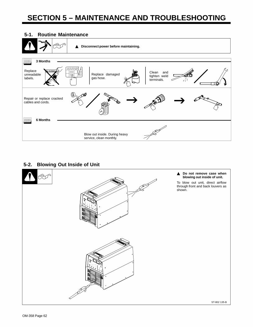
OM-358 Page 62
SECTION 5 – MAINTENANCE AND TROUBLESHOOTING
5-1. Routine Maintenance
� Disconnect power before maintaining.
3 Months
Replaceunreadablelabels.
Clean andtighten weldterminals.
Replace damagedgas hose.
Repair or replace crackedcables and cords.
6 Months
Blow out inside. During heavyservice, clean monthly.
5-2. Blowing Out Inside of Unit
ST-802 135-B
� Do not remove case whenblowing out inside of unit.
To blow out unit, direct airflowthrough front and back louvers asshown.

OM-358 Page 63
5-3. Voltmeter/Ammeter Help Displays
� All directions are in reference to thefront of the unit. All circuitry referred tois located inside the unit.
0 Help 0 Display
Indicates a short in the thermal protectioncircuitry located on the left side of the unit.Contact a Factory Authorized ServiceAgent if this display is shown.
1 Help 1 Display
Indicates a malfunction in the primary pow-er circuit caused by an overcurrent condi-tion in the primary IGBT switching circuit.Contact a Factory Authorized ServiceAgent if this display is shown.
2 Help 2 Display
Indicates an open in the thermal protectioncircuitry located on the left side of the unit.Contact a Factory Authorized ServiceAgent if this display is shown.
3 Help 3 Display
Indicates the left side of the unit has over-heated. The unit has shut down to allow thefan to cool it (see Section 3-3). Operation
will continue when the unit has cooled.
4 Help 4 Display
Indicates an open in the thermal protectioncircuitry located on the right side of the unit.Contact a Factory Authorized ServiceAgent if this display is shown.
5 Help 5 Display
Indicates the right side of the unit has over-heated. The unit has shut down to allow thefan to cool it (see Section 3-3). Operationwill continue when the unit has cooled.
6 Help 6 Display
Indicates that the input voltage is too lowand the unit has automatically shut down.Operation will continue when the voltage iswithin the operating range (±10%). Have anelectrician check the input voltage if this dis-play is shown.
7 Help 7 Display
Indicates that the input voltage is too highand the unit has automatically shut down.Operation will continue when the voltage iswithin the operating range (±10%). Have an
electrician check the input voltage if this dis-play is shown.
8 Help 8 Display
Indicates a malfunction in the secondarypower circuit of the unit. There is a highopen circuit condition. Contact a FactoryAuthorized Service Agent if this display isshown.
9 Help 9 Display
Indicates a short in the thermal protectioncircuitry located on the right side of the unit.Contact a Factory Authorized ServiceAgent if this display is shown.
10 Help 10 Display
Indicates torch trigger is depressed. Re-lease trigger to continue.
11 Help 12 Display
Indicates a non-allowable set-up on thefront panel.
12 Help 13 Display
Output disable open causing weld output tostop, but gas continues to flow.
1AV
2AV
3AV
HE.L P–1
HE.L P–2
HE.L P–3
4AV
HE.L P–4
5AV
HE.L P–5
6AV
HE.L P–6
7AV
HE.L P–7
8AV
HE.L P–8
0V
HE.L P–0
9AV
HE.L P–9
10AV
HE.L P10
A
11AV
HE.L P12
12AV
HE.L P13

OM-358 Page 64
5-4. Troubleshooting
Trouble Remedy
No weld output; unit completelyinoperative.
Place line disconnect switch in On position (see Section 3-16).
Check and replace line fuse(s), if necessary, or reset circuit breaker (see Section 3-16).
Check for proper input power connections (see Section 3-16).
No weld output; meter display On. If using remote control, be sure correct process is enabled to provide output control at Remote 14receptacle (see Sections 4-1 and 3-7).
Input voltage outside acceptable range of variation (see Section 3-15).
Check, repair, or replace remote control.
Unit overheated. Allow unit to cool with fan On (see Section 3-3).
Erratic or improper weld output. Use proper size and type of weld cable (see Section 3-6).
Clean and tighten all weld connections.
No 115 volts ac output at duplex recep-tacle.
Reset circuit breaker CB1 (see Section 3-5).
Fan not operating. Check for and remove anything blocking fan movement.
Have Factory Authorized Service Agent check fan motor.
Wandering arc Use proper size tungsten.
Use properly prepared tungsten.
Reduce gas flow rate.
Tungsten electrode oxidizing and not re- Shield weld zone from drafts.maining bright after conclusion of weld.
Increase postflow time.
Check and tighten all gas fittings.
Water in torch. Refer to torch manual.

OM-358 Page 65
Notes

OM-358 Page 66
SECTION 6 – ELECTRICAL DIAGRAM
Figure 5-1. Circuit Diagram
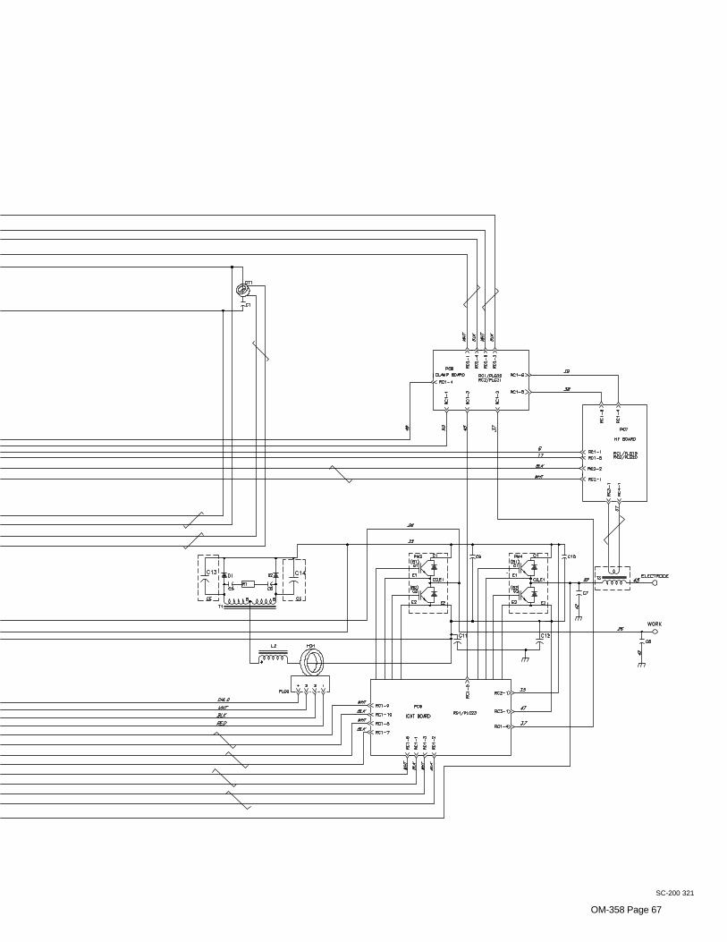
OM-358 Page 67
SC-200 321

OM-358 Page 68
SECTION 7 – HIGH FREQUENCY
7-1. Welding Processes Requiring High Frequency
high_freq 12/96 – S-0693
1 High-Frequency Voltage
TIG – helps arc jump air gapbetween torch and workpiece and/or stabilize the arc.1
TIG
Work
7-2. Incorrect Installation
50 ft(15 m)
S-0694
Sources of Direct High-FrequencyRadiation1 High-Frequency Source (welding
power source with built-in HF orseparate HF unit)
2 Weld Cables3 Torch4 Work Clamp5 Workpiece6 Work Table
Sources of Conduction of HighFrequency7 Input Power Cable8 Line Disconnect Device9 Input Supply Wiring
Sources of Reradiation of HighFrequency10 Ungrounded Metal Objects11 Lighting12 Wiring13 Water Pipes and Fixtures14 External Phone and Power Lines
Weld Zone
13
9
8
7
1
2
4 5 6
3
10
11, 12
14
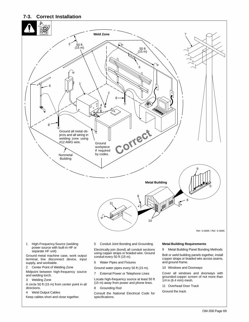
OM-358 Page 69
7-3. Correct Installation
1 High-Frequency Source (weldingpower source with built-in HF orseparate HF unit)
Ground metal machine case, work outputterminal, line disconnect device, inputsupply, and worktable.2 Center Point of Welding ZoneMidpoint between high-frequency sourceand welding torch.3 Welding ZoneA circle 50 ft (15 m) from center point in alldirections.4 Weld Output CablesKeep cables short and close together.
5 Conduit Joint Bonding and Grounding
Electrically join (bond) all conduit sectionsusing copper straps or braided wire. Groundconduit every 50 ft (15 m).
6 Water Pipes and Fixtures
Ground water pipes every 50 ft (15 m).
7 External Power or Telephone Lines
Locate high-frequency source at least 50 ft(15 m) away from power and phone lines.
8 Grounding Rod
Consult the National Electrical Code forspecifications.
Metal Building Requirements
9 Metal Building Panel Bonding Methods
Bolt or weld building panels together, installcopper straps or braided wire across seams,and ground frame.
10 Windows and Doorways
Cover all windows and doorways withgrounded copper screen of not more than1/4 in (6.4 mm) mesh.
11 Overhead Door Track
Ground the track.
Ref. S-0695 / Ref. S-0695
1
2
3 50 ft(15 m)
Weld Zone
4
7
50 ft(15 m)
8
5
8
6
Groundworkpieceif requiredby codes.
Ground all metal ob-jects and all wiring inwelding zone using#12 AWG wire.
NonmetalBuilding
9
11
10
Metal Building
88

Om-358 Page 70
SECTION 8 – SELECTING AND PREPARINGTUNGSTEN ELECTRODE
gtaw 7/97
For additional information, see your distributor for a handbook on the GasTungsten Arc Welding (GTAW) process.Wear clean gloves to preventcontamination of tungsten electrode.
NOTE
8-1. Selecting Tungsten Electrode
Amperage Range - Gas Type♦ - Polarity
Electrode Diameter DC – Argon – ElectrodeNegative/Straight Polarity
DC – Argon – ElectrodePositive/Reverse Polarity
AC – Argon – UsingHigh Frequency
AC – Argon – BalancedWave Using High Freq.
2% Thorium AlloyedTungsten (Red Band)
.010” Up to 25 * Up to 20 Up to 15
.020” 15-40 * 15-35 5-20
.040” 25-85 * 20-80 20-60
1/16” 50-160 10-20 50-150 60-120
3/32” 135-235 15-30 130-250 100-180
1/8” 250-400 25-40 225-360 160-250
5/32” 400-500 40-55 300-450 200-320
3/16” 500-750 55-80 400-500 290-390
1/4” 750-1000 80-125 600-800 340-525
♦ Typical argon shielding gas flow rates are 15 to 35 cfh (cubic feet per hour).
*Not Recommended.
The figures listed are intended as a guide and are a composite of recommendations from American Welding Society (AWS) and electrodemanufacturers.
8-2. Safety Information About Tungsten
Ref. S-0161
� Grinding the tungsten elec-trode produces dust and fly-ing sparks which can causeinjury and start fires. Use lo-cal exhaust (forced ventila-tion) at the grinder or wear anapproved respirator. ReadMSDS for safety information.Consider using tungstencontaining ceria, lanthana,or yttria instead of thoria.Grinding dust from thoriatedelectrodes contains low-lev-el radioactive material.Properly dispose of grinderdust in an environmentallysafe way. Wear proper face,hand, and body protection.Keep flammables away.
1 Tungsten Electrode WithBalled End
2 Pointed Tungsten Electrode
1
2

OM-358 Page 71
8-3. Preparing Tungsten For AC Or DC Electrode Negative (DCEN) Welding
Ref. S-0161 / Ref. S-0162
1 Tungsten Electrode
2 Tapered End
Grind end of tungsten on fine grit,hard abrasive wheel before weld-ing. Do not use wheel for other jobsor tungsten can become contami-nated causing lower weld quality.
3
Ideal Tungsten Preparation – Stable Arc
2-1/2 TimesElectrode Diameter
1 2
1 Stable Arc
2 Flat
Diameter of this flat determinesamperage capacity.
3 Grinding Wheel
Grinding wheel should be dedi-cated to grinding tungsten only.
4 Straight Ground
3
1
2
1 Arc Wander
2 Point
3 Grinding Wheel
Grinding wheel should be dedi-cated to grinding tungsten only.
4 Radial Ground2
1
4
Wrong Tungsten Preparation – Wandering Arc
4

Om-358 Page 72
SECTION 9 – GUIDELINES FOR TIG WELDING (GTAW)9-1. Positioning The Torch
Ref. ST-161 892
� Grinding the tungsten elec-trode produces dust and fly-ing sparks which can causeinjury and start fires. Use lo-cal exhaust (forced ventila-tion) at the grinder or wear anapproved respirator. ReadMSDS for safety information.Consider using cerium orlanthanum based tungsteninstead of thoriated. Tho-rium dust contains low-levelradioactive material. Proper-ly dispose of grinder dust inan environmentally safe way.Wear proper face, hand, andbody protection. Keep flam-mables away.
1 Workpiece
Make sure workpiece is cleanbefore welding.
2 Work Clamp
Place as close to the weld aspossible.
3 Torch
4 Filler Rod (If Applicable)
5 Gas Cup
6 Tungsten Electrode
Select and prepare tungstenaccording to Sections 8-1 and 8-3.
Guidelines:
The inside diameter of the gas cupshould be at least three times thetungsten diameter to provide ade-quate shielding gas coverage. (Forexample, if tungsten is 1/16 indiameter, gas cup should be aminimum of 3/16 in diameter.
Tungsten extension is the distancethe tungsten extends out gas cup oftorch.
The tungsten extension should beno greater than the inside diameterof the gas cup.
Arc length is the distance from thetungsten to the workpiece.
1
10–25°
10–15°
6
2
3
4
90°
4
5
3/16 in
1/16 in
65
Bottom View Of Gas Cup

OM-358 Page 73
9-2. Torch Movement During Welding
ST-162 002-B
Tungsten Without Filler Rod
Tungsten With Filler Rod
Form pool Tilt torch Move torch to frontof pool. Repeat process.
75°
75°Welding direction
Form pool Tilt torch Add filler metal
Move torch to frontof pool. Repeat process.
Remove rod
Welding direction 15°
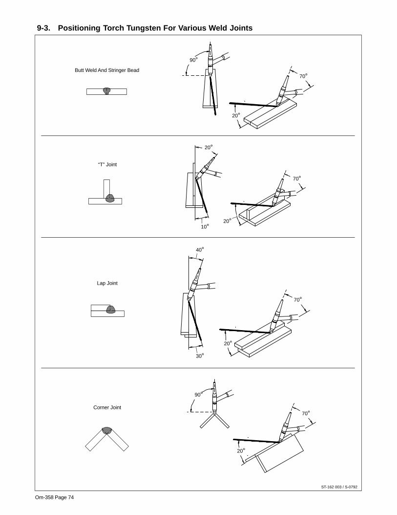
Om-358 Page 74
9-3. Positioning Torch Tungsten For Various Weld Joints
ST-162 003 / S-0792
70°
70°
90°
20°
20°
10°20°
70°
40°
30°
20°
70°
90°
20°
Butt Weld And Stringer Bead
“T” Joint
Lap Joint
Corner Joint

OM-358 Page 75
Notes

OM-358 Page 76
SECTION 10 – PARTS LIST
Figure 10-1. Main Assembly ST-801 870-J
� Hardware is common andnot available unless listed.
13
4
5
1314
15
16
1718
19
20
21
22
23
24
25
26
27
28
29
30–(
PC
3)
31
3233
20
39
39
41
(Fig
.10–
2)–4
3
PC
2
10 11
12
34
35
36
40 37
3837
44
PC
1
PC
8
6
7
8
9
46
45
47

OM-358 Page 77
Quantity
DescriptionPartNo.
Dia.Mkgs.
ItemNo. 230/460
Model
400 CE
Figure 10-1. Main Assembly
1 195 585 HANDLE, rubberized carrying 2 2. . . . . . . . . . . . . . . . . . . . . . . . . . . . . . . . . . . . . . . . . . . . . . . . . . . . . 3 138 442 LABEL, caution falling 2. . . . . . . . . . . . . . . . . . . . . . . . . . . . . . . . . . . . . . . . . . . . . . . . . . . . . . . 3 179 309 LABEL, caution falling 2. . . . . . . . . . . . . . . . . . . . . . . . . . . . . . . . . . . . . . . . . . . . . . . . . . . . . . . . . . . . . . . 4 +175 148 WRAPPER 1 1. . . . . . . . . . . . . . . . . . . . . . . . . . . . . . . . . . . . . . . . . . . . . . . . . . . . . . . . . . . . . . . . . . . .
175 256 INSULATOR, side RH & LH 2 2. . . . . . . . . . . . . . . . . . . . . . . . . . . . . . . . . . . . . . . . . . . . . . . . . . . . . . . . . . 5 134 327 LABEL, warning general precautionary 2. . . . . . . . . . . . . . . . . . . . . . . . . . . . . . . . . . . . . . . . 5 179 310 LABEL, warning general precautionary 2. . . . . . . . . . . . . . . . . . . . . . . . . . . . . . . . . . . . . . . . . . . . . . . . 6 PC8 197 988 CIRCUIT CARD ASSEMBLY, clamp 1 1. . . . . . . . . . . . . . . . . . . . . . . . . . . . . . . . . . . . . . . . . .
PLG21 115 094 CONNECTOR & SOCKETS 1 1. . . . . . . . . . . . . . . . . . . . . . . . . . . . . . . . . . . . . . . . . . . . . . . . . . PLG22 115 093 CONNECTOR & SOCKETS 1 1. . . . . . . . . . . . . . . . . . . . . . . . . . . . . . . . . . . . . . . . . . . . . . . . . .
7 183 613 INSULATOR, PC card clamp 1 1. . . . . . . . . . . . . . . . . . . . . . . . . . . . . . . . . . . . . . . . . . . . . . . . . . . . . . 8 182 498 BRACKET, mtg PC card clamp 1. . . . . . . . . . . . . . . . . . . . . . . . . . . . . . . . . . . . . . . . . . . . . . . . . . . . . . . 9 PC1 201 285 CIRCUIT CARD ASSEMBLY, control 1. . . . . . . . . . . . . . . . . . . . . . . . . . . . . . . . . . . . . 9 PC1 201 282 CIRCUIT CARD ASSEMBLY, control 1. . . . . . . . . . . . . . . . . . . . . . . . . . . . . . . . . . . . . . . . . . . . .
PLG2 115 091 CONNECTOR & SOCKETS 1 1. . . . . . . . . . . . . . . . . . . . . . . . . . . . . . . . . . . . . . . . . . . . . . . . . . . PLG3 115 092 CONNECTOR & SOCKETS 1 1. . . . . . . . . . . . . . . . . . . . . . . . . . . . . . . . . . . . . . . . . . . . . . . . . . . PLG4 131 054 CONNECTOR & SOCKETS 1 1. . . . . . . . . . . . . . . . . . . . . . . . . . . . . . . . . . . . . . . . . . . . . . . . . . PLG5 115 091 CONNECTOR & SOCKETS 1 1. . . . . . . . . . . . . . . . . . . . . . . . . . . . . . . . . . . . . . . . . . . . . . . . . . . PLG7 130 203 CONNECTOR & SOCKETS 1 1. . . . . . . . . . . . . . . . . . . . . . . . . . . . . . . . . . . . . . . . . . . . . . . . . . PLG8 115 092 CONNECTOR & SOCKETS 1 1. . . . . . . . . . . . . . . . . . . . . . . . . . . . . . . . . . . . . . . . . . . . . . . . . . . PLG9 131 204 CONNECTOR & SOCKETS 1 1. . . . . . . . . . . . . . . . . . . . . . . . . . . . . . . . . . . . . . . . . . . . . . . . . .
PLG10 115 094 CONNECTOR & SOCKETS 1 1. . . . . . . . . . . . . . . . . . . . . . . . . . . . . . . . . . . . . . . . . . . . . . . . . . 10 T2 ♦ 193 311 TRANSFORMER, control 1. . . . . . . . . . . . . . . . . . . . . . . . . . . . . . . . . . . . . . . . . . . . . . . . . . . . . . 10 T2 ♦ 193 310 TRANSFORMER, control 1. . . . . . . . . . . . . . . . . . . . . . . . . . . . . . . . . . . . . . . . . . . . . . 11 ♦ 187 461 BRACKET, mtg aux transformer 1. . . . . . . . . . . . . . . . . . . . . . . . . . . . . . . . . . . . . . . . . . . . . . . . . . . . . 12 T2 189 536 TRANSFORMER, control 1. . . . . . . . . . . . . . . . . . . . . . . . . . . . . . . . . . . . . . . . . . . . . . . 12 T2 180 873 TRANSFORMER, control 1. . . . . . . . . . . . . . . . . . . . . . . . . . . . . . . . . . . . . . . . . . . . . . . . . . . . . . .
RC10 166 679 CONNECTOR & SOCKETS 1 1. . . . . . . . . . . . . . . . . . . . . . . . . . . . . . . . . . . . . . . . . . . . . . . . . . PLG10 166 680 CONNECTOR & PINS 1 1. . . . . . . . . . . . . . . . . . . . . . . . . . . . . . . . . . . . . . . . . . . . . . . . . . . . . .
13 GS1 133 873 VALVE, 24VDC 2way 1 1. . . . . . . . . . . . . . . . . . . . . . . . . . . . . . . . . . . . . . . . . . . . . . . . . . . . . . . 14 ♦ 189 033 RECEPTACLE, str dx grd 2P 3W 15A 1 1. . . . . . . . . . . . . . . . . . . . . . . . . . . . . . . . . . . . . . . . . . . . . 15 CB1 ♦ 083 432 CIRCUIT BREAKER, 1P 10A 250VAC 1. . . . . . . . . . . . . . . . . . . . . . . . . . . . . . . . . . 15 CB1 ♦ 161 078 CIRCUIT BREAKER, 1P 7A 250VAC 1. . . . . . . . . . . . . . . . . . . . . . . . . . . . . . . . . . . . . . . . . . . 16 605 227 NUT, .750-14 knurled 1 1. . . . . . . . . . . . . . . . . . . . . . . . . . . . . . . . . . . . . . . . . . . . . . . . . . . . . . . . . . . . 17 182 205 PANEL, rear 1 1. . . . . . . . . . . . . . . . . . . . . . . . . . . . . . . . . . . . . . . . . . . . . . . . . . . . . . . . . . . . . . . . . . . . 18 PLATE, identification rear. . . . . . . . . . . . . . . . . . . . . . . . . . .
(order by model and serial number) 1 1. . . . . . . . . . . . . . . . . . . . . . . . . . . . . . 19 ♦ 175 282 COVER, receptacle 1 1. . . . . . . . . . . . . . . . . . . . . . . . . . . . . . . . . . . . . . . . . . . . . . . . . . . . . . . . . . . . . 20 175 138 BOX, louver 2 2. . . . . . . . . . . . . . . . . . . . . . . . . . . . . . . . . . . . . . . . . . . . . . . . . . . . . . . . . . . . . . . . . . . . 21 182 561 CABLE, pwr 1 1. . . . . . . . . . . . . . . . . . . . . . . . . . . . . . . . . . . . . . . . . . . . . . . . . . . . . . . . . . . . . . . . . . . . 22 175 213 BUSHING, strain relief .472/.787 ID 1 1. . . . . . . . . . . . . . . . . . . . . . . . . . . . . . . . . . . . . . . . . . . . . . . . 23 182 445 NUT, stl locking 1 1. . . . . . . . . . . . . . . . . . . . . . . . . . . . . . . . . . . . . . . . . . . . . . . . . . . . . . . . . . . . . . . . . 24 176 226 INSULATOR, switch power 1 1. . . . . . . . . . . . . . . . . . . . . . . . . . . . . . . . . . . . . . . . . . . . . . . . . . . . . . . 25 S1 128 756 SWITCH, tgl 3PST 40A 600VAC (Power Switch) 1 1. . . . . . . . . . . . . . . . . . . . . . . . . . . . . . . . 26 PC2 185 090 CIRCUIT CARD, assembly 1 1. . . . . . . . . . . . . . . . . . . . . . . . . . . . . . . . . . . . . . . . . . . . . . . . . .
176 879 SCREW, M5–.8–2 18 18. . . . . . . . . . . . . . . . . . . . . . . . . . . . . . . . . . . . . . . . . . . . . . . . . . . . . . . . . . . . . . . . . PLG13 131 204 CONNECTOR & SOCKETS 1 1. . . . . . . . . . . . . . . . . . . . . . . . . . . . . . . . . . . . . . . . . . . . . . . . . PLG14 115 094 CONNECTOR & SOCKETS 1 1. . . . . . . . . . . . . . . . . . . . . . . . . . . . . . . . . . . . . . . . . . . . . . . . . .
179 626 BUS BAR, interconnecting 1 1. . . . . . . . . . . . . . . . . . . . . . . . . . . . . . . . . . . . . . . . . . . . . . . . . . . . . . . . . . . 27 +175 132 BASE 1 1. . . . . . . . . . . . . . . . . . . . . . . . . . . . . . . . . . . . . . . . . . . . . . . . . . . . . . . . . . . . . . . . . . . . . . . . . 28 173 693 FOOT, mtg unit 4 4. . . . . . . . . . . . . . . . . . . . . . . . . . . . . . . . . . . . . . . . . . . . . . . . . . . . . . . . . . . . . . . . . 29 176 736 SCREW, mtg foot 4 4. . . . . . . . . . . . . . . . . . . . . . . . . . . . . . . . . . . . . . . . . . . . . . . . . . . . . . . . . . . . . . . 30 PC3 200 339 CIRCUIT CARD, front panel (DX and SD models) (consisting of) 1 1. . . . . . . . . . . . . . . . . . 30 PC3 200 340 CIRCUIT CARD, front panel (LX models) (consisting of) 1 1. . . . . . . . . . . . . . . . . . . . . . . . .
DD1-6 186 914 LED 6 6. . . . . . . . . . . . . . . . . . . . . . . . . . . . . . . . . . . . . . . . . . . . . . . . . . . . . . . . . . . . . . . . . . . . . . . PLG17, 18 131 054 CONNECTOR & SOCKETS 1 1. . . . . . . . . . . . . . . . . . . . . . . . . . . . . . . . . . . . . . . . . . . . . .

OM-358 Page 78
Quantity
DescriptionPartNo.
Dia.Mkgs.
ItemNo. 230/460
Model
400 CE
Figure 10-1. Main Assembly (Continued)
PLG26 115 091 CONNECTOR & SOCKETS 1 1. . . . . . . . . . . . . . . . . . . . . . . . . . . . . . . . . . . . . . . . . . . . . . . . . . PLG11 115 092 RECEPTACLE, w/leads & plug 1 1. . . . . . . . . . . . . . . . . . . . . . . . . . . . . . . . . . . . . . . . . . . . . . . . .
31 FM 175 084 MOTOR, fan 24VDC 3000RPM 1 1. . . . . . . . . . . . . . . . . . . . . . . . . . . . . . . . . . . . . . . . . . . . . . 135 635 CONNECTOR & SOCKETS 1 1. . . . . . . . . . . . . . . . . . . . . . . . . . . . . . . . . . . . . . . . . . . . . . . . . . . . . . . . .
32 200 320 PANEL, front 1 1. . . . . . . . . . . . . . . . . . . . . . . . . . . . . . . . . . . . . . . . . . . . . . . . . . . . . . . . . . . . . . . . . . . 33 191 173 NAMEPLATE, RH 1 1. . . . . . . . . . . . . . . . . . . . . . . . . . . . . . . . . . . . . . . . . . . . . . . . . . . . . . . . . . . . . . . 33 191 172 NAMEPLATE, RH W/Optional 10-pin Installed (LX models) 1 1. . . . . . . . . . . . . . . . . . . . . . . . . . . 34 RC2 ♦ 191 302 CONNECTOR & SOCKETS 1 1. . . . . . . . . . . . . . . . . . . . . . . . . . . . . . . . . . . . . . . . . . . . . . . . 34 RC2 ♦ 197 181 CONNECTOR & SOCKETS (LX models) 1 1. . . . . . . . . . . . . . . . . . . . . . . . . . . . . . . . . . . . . 35 RC1 188 186 CONNECTOR & SOCKETS 1 1. . . . . . . . . . . . . . . . . . . . . . . . . . . . . . . . . . . . . . . . . . . . . . . . . 36 192 018 NAMEPLATE, LH 1 1. . . . . . . . . . . . . . . . . . . . . . . . . . . . . . . . . . . . . . . . . . . . . . . . . . . . . . . . . . . . . . . 37 185 703 RECEPTACLE, twist lock assembly 2 2. . . . . . . . . . . . . . . . . . . . . . . . . . . . . . . . . . . . . . . . . . . . . . . . 38 187 235 RECEPTACLE, female gas 1. . . . . . . . . . . . . . . . . . . . . . . . . . . . . . . . . . . . . . . . . . . . . . . . . 38 188 192 RECEPTACLE, male gas 1. . . . . . . . . . . . . . . . . . . . . . . . . . . . . . . . . . . . . . . . . . . . . . . . . . . . . . . . . . . 39 C7,8 186 543 CAPACITOR ASSEMBLY 2 2. . . . . . . . . . . . . . . . . . . . . . . . . . . . . . . . . . . . . . . . . . . . . . . . . . 40 198 707 MEMBRANE PANEL (DX, LX models) 1. . . . . . . . . . . . . . . . . . . . . . . . . . . . . . . . . . . . . . . . 40 198 710 MEMBRANE PANEL (SD models) 1. . . . . . . . . . . . . . . . . . . . . . . . . . . . . . . . . . . . . . . . . . . . 40 198 713 MEMBRANE PANEL (DX, LX, CE models) 1. . . . . . . . . . . . . . . . . . . . . . . . . . . . . . . . . . . . . . . . . . . . 40 198 715 MEMBRANE PANEL (SD CE models) 1. . . . . . . . . . . . . . . . . . . . . . . . . . . . . . . . . . . . . . . . . . . . . . . . . 41 174 991 KNOB, encoder 1 1. . . . . . . . . . . . . . . . . . . . . . . . . . . . . . . . . . . . . . . . . . . . . . . . . . . . . . . . . . . . . . . . . 43 Fig 10-2 WINDTUNNELS w/COMPONENTS 1 1. . . . . . . . . . . . . . . . . . . . . . . . . . . . . . . . . . . . . . . . . . . . . . . 44 182 108 CHOKE 1. . . . . . . . . . . . . . . . . . . . . . . . . . . . . . . . . . . . . . . . . . . . . . . . . . . . . . . . . . . . . . . . . . . . . . . . . . . 45 182 826 LABEL, warning electric shock power cord 1. . . . . . . . . . . . . . . . . . . . . . . . . . . . . . . . . . . . . 46 148 329 LABEL, caution incorrect voltage 1. . . . . . . . . . . . . . . . . . . . . . . . . . . . . . . . . . . . . . . . . . . . . 47 ♦ 059 266 RELAY, encl 120 VAC DPDT 10A/120VAC 8-Pin Flange Mtg 1. . . . . . . . . . . . . . . . . . . .
+When ordering a component originally displaying a precautionary label, the label should also be ordered.♦ OptionalTo maintain the factory original performance of your equipment, use only Manufacturer’s SuggestedReplacement Parts. Model and serial number required when ordering parts from your local distributor.
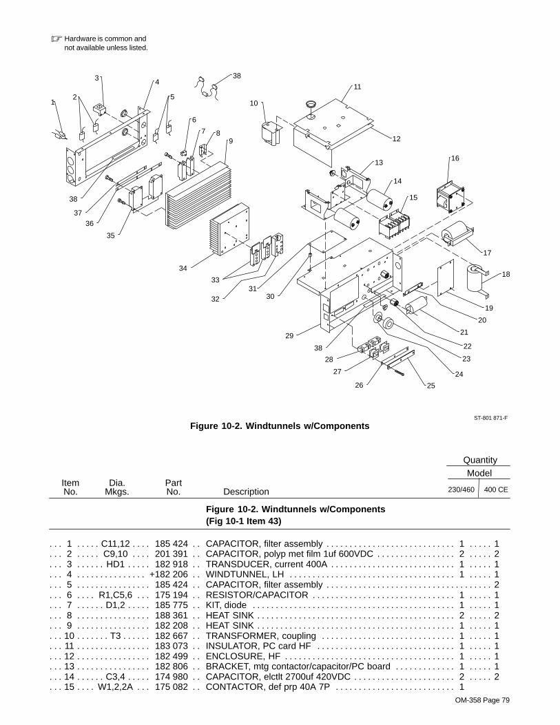
OM-358 Page 79
Figure 10-2. Windtunnels w/ComponentsST-801 871-F
� Hardware is common andnot available unless listed.
12
3 4
6
79
10
11
12
13
14
15
16
17
18
22
23
24
2526
27
28
29
3031
32
33
34
35
3637
5
19
20
21
8
38
38
38
Figure 10-2. Windtunnels w/Components(Fig 10-1 Item 43)
Quantity
DescriptionPartNo.
Dia.Mkgs.
ItemNo. 230/460
Model
400 CE
1 C11,12 185 424 CAPACITOR, filter assembly 1 1. . . . . . . . . . . . . . . . . . . . . . . . . . . . . . . . . . . . . . . . . . . . . . . 2 C9,10 201 391 CAPACITOR, polyp met film 1uf 600VDC 2 2. . . . . . . . . . . . . . . . . . . . . . . . . . . . . . . . . . . . 3 HD1 182 918 TRANSDUCER, current 400A 1 1. . . . . . . . . . . . . . . . . . . . . . . . . . . . . . . . . . . . . . . . . . . . . . . . 4 +182 206 WINDTUNNEL, LH 1 1. . . . . . . . . . . . . . . . . . . . . . . . . . . . . . . . . . . . . . . . . . . . . . . . . . . . . . . . . . . . . 5 185 424 CAPACITOR, filter assembly 2. . . . . . . . . . . . . . . . . . . . . . . . . . . . . . . . . . . . . . . . . . . . . . . . . . . . . . . . . 6 R1,C5,6 175 194 RESISTOR/CAPACITOR 1 1. . . . . . . . . . . . . . . . . . . . . . . . . . . . . . . . . . . . . . . . . . . . . . . . 7 D1,2 185 775 KIT, diode 1 1. . . . . . . . . . . . . . . . . . . . . . . . . . . . . . . . . . . . . . . . . . . . . . . . . . . . . . . . . . . . . . . . . 8 188 361 HEAT SINK 2 2. . . . . . . . . . . . . . . . . . . . . . . . . . . . . . . . . . . . . . . . . . . . . . . . . . . . . . . . . . . . . . . . . . . . . 9 182 208 HEAT SINK 1 1. . . . . . . . . . . . . . . . . . . . . . . . . . . . . . . . . . . . . . . . . . . . . . . . . . . . . . . . . . . . . . . . . . . . .
10 T3 182 667 TRANSFORMER, coupling 1 1. . . . . . . . . . . . . . . . . . . . . . . . . . . . . . . . . . . . . . . . . . . . . . . . . . . . 11 183 073 INSULATOR, PC card HF 1 1. . . . . . . . . . . . . . . . . . . . . . . . . . . . . . . . . . . . . . . . . . . . . . . . . . . . . . . . 12 182 499 ENCLOSURE, HF 1 1. . . . . . . . . . . . . . . . . . . . . . . . . . . . . . . . . . . . . . . . . . . . . . . . . . . . . . . . . . . . . . . 13 182 806 BRACKET, mtg contactor/capacitor/PC board 1 1. . . . . . . . . . . . . . . . . . . . . . . . . . . . . . . . . . . . . . . 14 C3,4 174 980 CAPACITOR, elctlt 2700uf 420VDC 2 2. . . . . . . . . . . . . . . . . . . . . . . . . . . . . . . . . . . . . . . . . . . 15 W1,2,2A 175 082 CONTACTOR, def prp 40A 7P 1. . . . . . . . . . . . . . . . . . . . . . . . . . . . . . . . . . . . . .
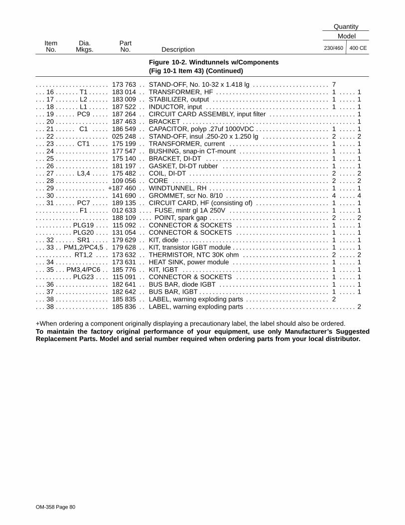
OM-358 Page 80
Figure 10-2. Windtunnels w/Components(Fig 10-1 Item 43) (Continued)
Quantity
DescriptionPartNo.
Dia.Mkgs.
ItemNo. 230/460
Model
400 CE
173 763 STAND-OFF, No. 10-32 x 1.418 lg 7. . . . . . . . . . . . . . . . . . . . . . . . . . . . . . . . . . . . . . . . . . . . . . . 16 T1 183 014 TRANSFORMER, HF 1 1. . . . . . . . . . . . . . . . . . . . . . . . . . . . . . . . . . . . . . . . . . . . . . . . . . . . . . . . . 17 L2 183 009 STABILIZER, output 1 1. . . . . . . . . . . . . . . . . . . . . . . . . . . . . . . . . . . . . . . . . . . . . . . . . . . . . . . . . . 18 L1 187 522 INDUCTOR, input 1 1. . . . . . . . . . . . . . . . . . . . . . . . . . . . . . . . . . . . . . . . . . . . . . . . . . . . . . . . . . . . 19 PC9 187 264 CIRCUIT CARD ASSEMBLY, input filter 1. . . . . . . . . . . . . . . . . . . . . . . . . . . . . . . . . . . . . . . . . . 20 187 463 BRACKET 1. . . . . . . . . . . . . . . . . . . . . . . . . . . . . . . . . . . . . . . . . . . . . . . . . . . . . . . . . . . . . . . . . . . . . . . . . 21 C1 186 549 CAPACITOR, polyp .27uf 1000VDC 1 1. . . . . . . . . . . . . . . . . . . . . . . . . . . . . . . . . . . . . . . . . . . 22 025 248 STAND-OFF, insul .250-20 x 1.250 lg 2 2. . . . . . . . . . . . . . . . . . . . . . . . . . . . . . . . . . . . . . . . . . . . . . 23 CT1 175 199 TRANSFORMER, current 1 1. . . . . . . . . . . . . . . . . . . . . . . . . . . . . . . . . . . . . . . . . . . . . . . . . . . 24 177 547 BUSHING, snap-in CT-mount 1 1. . . . . . . . . . . . . . . . . . . . . . . . . . . . . . . . . . . . . . . . . . . . . . . . . . . . . 25 175 140 BRACKET, DI-DT 1 1. . . . . . . . . . . . . . . . . . . . . . . . . . . . . . . . . . . . . . . . . . . . . . . . . . . . . . . . . . . . . . . 26 181 197 GASKET, DI-DT rubber 1 1. . . . . . . . . . . . . . . . . . . . . . . . . . . . . . . . . . . . . . . . . . . . . . . . . . . . . . . . . . 27 L3,4 175 482 COIL, DI-DT 2 2. . . . . . . . . . . . . . . . . . . . . . . . . . . . . . . . . . . . . . . . . . . . . . . . . . . . . . . . . . . . . . . 28 109 056 CORE 2 2. . . . . . . . . . . . . . . . . . . . . . . . . . . . . . . . . . . . . . . . . . . . . . . . . . . . . . . . . . . . . . . . . . . . . . . . . 29 +187 460 WINDTUNNEL, RH 1 1. . . . . . . . . . . . . . . . . . . . . . . . . . . . . . . . . . . . . . . . . . . . . . . . . . . . . . . . . . . . . 30 141 690 GROMMET, scr No. 8/10 4 4. . . . . . . . . . . . . . . . . . . . . . . . . . . . . . . . . . . . . . . . . . . . . . . . . . . . . . . . . 31 PC7 189 135 CIRCUIT CARD, HF (consisting of) 1 1. . . . . . . . . . . . . . . . . . . . . . . . . . . . . . . . . . . . . . . . . . .
F1 012 633 FUSE, mintr gl 1A 250V 1 1. . . . . . . . . . . . . . . . . . . . . . . . . . . . . . . . . . . . . . . . . . . . . . . . . . . . . . . . . . 188 109 POINT, spark gap 2 2. . . . . . . . . . . . . . . . . . . . . . . . . . . . . . . . . . . . . . . . . . . . . . . . . . . . . . . . . . . . . . . . . . .
PLG19 115 092 CONNECTOR & SOCKETS 1 1. . . . . . . . . . . . . . . . . . . . . . . . . . . . . . . . . . . . . . . . . . . . . . . . . . PLG20 131 054 CONNECTOR & SOCKETS 1 1. . . . . . . . . . . . . . . . . . . . . . . . . . . . . . . . . . . . . . . . . . . . . . . . . .
32 SR1 179 629 KIT, diode 1 1. . . . . . . . . . . . . . . . . . . . . . . . . . . . . . . . . . . . . . . . . . . . . . . . . . . . . . . . . . . . . . . . . 33 PM1,2/PC4,5 179 628 KIT, transistor IGBT module 1 1. . . . . . . . . . . . . . . . . . . . . . . . . . . . . . . . . . . . . . . . . .
RT1,2 173 632 THERMISTOR, NTC 30K ohm 2 2. . . . . . . . . . . . . . . . . . . . . . . . . . . . . . . . . . . . . . . . . . . . . . . . 34 173 631 HEAT SINK, power module 1 1. . . . . . . . . . . . . . . . . . . . . . . . . . . . . . . . . . . . . . . . . . . . . . . . . . . . . . . 35 PM3,4/PC6 185 776 KIT, IGBT 1 1. . . . . . . . . . . . . . . . . . . . . . . . . . . . . . . . . . . . . . . . . . . . . . . . . . . . . . . . . . .
PLG23 115 091 CONNECTOR & SOCKETS 1 1. . . . . . . . . . . . . . . . . . . . . . . . . . . . . . . . . . . . . . . . . . . . . . . . . . 36 182 641 BUS BAR, diode IGBT 1 1. . . . . . . . . . . . . . . . . . . . . . . . . . . . . . . . . . . . . . . . . . . . . . . . . . . . . . . . . . . 37 182 642 BUS BAR, IGBT 1 1. . . . . . . . . . . . . . . . . . . . . . . . . . . . . . . . . . . . . . . . . . . . . . . . . . . . . . . . . . . . . . . . . 38 185 835 LABEL, warning exploding parts 2. . . . . . . . . . . . . . . . . . . . . . . . . . . . . . . . . . . . . . . . . . . . . . 38 185 836 LABEL, warning exploding parts 2. . . . . . . . . . . . . . . . . . . . . . . . . . . . . . . . . . . . . . . . . . . . . . . . . . . . . .
+When ordering a component originally displaying a precautionary label, the label should also be ordered.To maintain the factory original performance of your equipment, use only Manufacturer’s SuggestedReplacement Parts. Model and serial number required when ordering parts from your local distributor.

Warranty Questions?
Call1-800-4-A-MILLERfor your localMiller distributor.
miller_warr 7/00
Your distributor also givesyou ...
ServiceYou always get the fast,reliable response youneed. Most replacementparts can be in yourhands in 24 hours.
SupportNeed fast answers to thetough welding questions?Contact your distributor.The expertise of thedistributor and Miller isthere to help you, everystep of the way.
Effective January 1, 2000(Equipment with a serial number preface of “LA” or newer)This limited warranty supersedes all previous Miller warranties and is exclusive with no other
guarantees or warranties expressed or implied.
LIMITED WARRANTY – Subject to the terms and conditionsbelow, Miller Electric Mfg. Co., Appleton, Wisconsin, warrantsto its original retail purchaser that new Miller equipment soldafter the effective date of this limited warranty is free of defectsin material and workmanship at the time it is shipped by Miller.THIS WARRANTY IS EXPRESSLY IN LIEU OF ALL OTHERWARRANTIES, EXPRESS OR IMPLIED, INCLUDING THEWARRANTIES OF MERCHANTABILITY AND FITNESS.
Within the warranty periods listed below, Miller will repair orreplace any warranted parts or components that fail due tosuch defects in material or workmanship. Miller must benotified in writing within thirty (30) days of such defect orfailure, at which time Miller will provide instructions on thewarranty claim procedures to be followed.
Miller shall honor warranty claims on warranted equipmentlisted below in the event of such a failure within the warrantytime periods. All warranty time periods start on the date thatthe equipment was delivered to the original retail purchaser, orone year after the equipment is sent to a North Americandistributor or eighteen months after the equipment is sent to anInternational distributor.
1. 5 Years Parts – 3 Years Labor
* Original main power rectifiers* Inverters (input and output rectifiers only)
2. 3 Years — Parts and Labor
* Transformer/Rectifier Power Sources* Plasma Arc Cutting Power Sources* Semi-Automatic and Automatic Wire Feeders* Inverter Power Supplies* Intellitig* Engine Driven Welding Generators
(NOTE: Engines are warranted separately bythe engine manufacturer.)
3. 1 Year — Parts and Labor
* DS-2 Wire Feeder* Motor Driven Guns (w/exception of Spoolmate
185 & Spoolmate 250)* Process Controllers* Positioners and Controllers* Automatic Motion Devices* RFCS Foot Controls* Induction Heating Power Sources* Water Coolant Systems* HF Units* Grids* Maxstar 140* Spot Welders* Load Banks* Miller Cyclomatic Equipment* Running Gear/Trailers* Plasma Cutting Torches (except APT & SAF
Models)* Field Options
(NOTE: Field options are covered under TrueBlue for the remaining warranty period of theproduct they are installed in, or for a minimum ofone year — whichever is greater.)
4. 6 Months — Batteries
5. 90 Days — Parts
* MIG Guns/TIG Torches* Induction Heating Coils and Blankets
* APT, ZIPCUT & PLAZCUT Model Plasma CuttingTorches
* Remote Controls
* Accessory Kits
* Replacement Parts (No labor)
* Spoolmate 185 & Spoolmate 250
* Canvas Covers
Miller’s True Blue Limited Warranty shall not apply to:
1. Consumable components; such as contact tips,cutting nozzles, contactors, brushes, slip rings,relays or parts that fail due to normal wear.
2. Items furnished by Miller, but manufactured by others,such as engines or trade accessories. These items arecovered by the manufacturer’s warranty, if any.
3. Equipment that has been modified by any party otherthan Miller, or equipment that has been improperlyinstalled, improperly operated or misused based uponindustry standards, or equipment which has not hadreasonable and necessary maintenance, or equipmentwhich has been used for operation outside of thespecifications for the equipment.
MILLER PRODUCTS ARE INTENDED FOR PURCHASEAND USE BY COMMERCIAL/INDUSTRIAL USERS ANDPERSONS TRAINED AND EXPERIENCED IN THE USEAND MAINTENANCE OF WELDING EQUIPMENT.
In the event of a warranty claim covered by this warranty, theexclusive remedies shall be, at Miller’s option: (1) repair; or (2)replacement; or, where authorized in writing by Miller inappropriate cases, (3) the reasonable cost of repair orreplacement at an authorized Miller service station; or (4)payment of or credit for the purchase price (less reasonabledepreciation based upon actual use) upon return of the goodsat customer’s risk and expense. Miller’s option of repair orreplacement will be F.O.B., Factory at Appleton, Wisconsin, orF.O.B. at a Miller authorized service facility as determined byMiller. Therefore no compensation or reimbursement fortransportation costs of any kind will be allowed.
TO THE EXTENT PERMITTED BY LAW, THE REMEDIESPROVIDED HEREIN ARE THE SOLE AND EXCLUSIVEREMEDIES. IN NO EVENT SHALL MILLER BE LIABLE FORDIRECT, INDIRECT, SPECIAL, INCIDENTAL ORCONSEQUENTIAL DAMAGES (INCLUDING LOSS OFPROFIT), WHETHER BASED ON CONTRACT, TORT ORANY OTHER LEGAL THEORY.
ANY EXPRESS WARRANTY NOT PROVIDED HEREINAND ANY IMPLIED WARRANTY, GUARANTY ORREPRESENTATION AS TO PERFORMANCE, AND ANYREMEDY FOR BREACH OF CONTRACT TORT OR ANYOTHER LEGAL THEORY WHICH, BUT FOR THISPROVISION, MIGHT ARISE BY IMPLICATION,OPERATION OF LAW, CUSTOM OF TRADE OR COURSEOF DEALING, INCLUDING ANY IMPLIED WARRANTY OFMERCHANTABILITY OR FITNESS FOR PARTICULARPURPOSE, WITH RESPECT TO ANY AND ALLEQUIPMENT FURNISHED BY MILLER IS EXCLUDED ANDDISCLAIMED BY MILLER.
Some states in the U.S.A. do not allow limitations of how longan implied warranty lasts, or the exclusion of incidental,indirect, special or consequential damages, so the abovelimitation or exclusion may not apply to you. This warrantyprovides specific legal rights, and other rights may beavailable, but may vary from state to state.
In Canada, legislation in some provinces provides for certainadditional warranties or remedies other than as stated herein,and to the extent that they may not be waived, the limitationsand exclusions set out above may not apply. This LimitedWarranty provides specific legal rights, and other rights maybe available, but may vary from province to province.

PRINTED IN USA 2000 Miller Electric Mfg. Co. 6/00
Miller Electric Mfg. Co.An Illinois Tool Works Company1635 West Spencer StreetAppleton, WI 54914 USA
International Headquarters–USAUSA Phone: 920-735-4505 Auto-AttendedUSA & Canada FAX: 920-735-4134International FAX: 920-735-4125
European Headquarters –United KingdomPhone: 44 (0) 1204-593493FAX: 44 (0) 1204-598066
www.MillerWelds.com
Model Name Serial/Style Number
Purchase Date (Date which equipment was delivered to original customer.)
Distributor
Address
City
State Zip
Please complete and retain with your personal records.
Always provide Model Name and Serial/Style Number.
Call 1-800-4-A-Miller or see our website at www.MillerWelds.comto locate a DISTRIBUTOR or SERVICE AGENCY near you.
Welding Supplies and Consumables
Options and Accessories
Personal Safety Equipment
Service and Repair
Replacement Parts
Training (Schools, Videos, Books)
Technical Manuals (Servicing Informationand Parts)
Circuit Diagrams
Welding Process Handbooks
Contact the Delivering Carrier for:
For assistance in filing or settling claims,contact your distributor and/or equipmentmanufacturer’s Transportation Department.
For Service
Owner’s Record
File a claim for loss or damage duringshipment.
Contact your Distributor for: