dynatron solaris plus series service manual rev. 6 august ... solaris plus service... · dynatron...
TRANSCRIPT

DYNATRON SOLARIS® PLUS SERIES | SERVICE MANUAL REV. 6 | AUGUST 29, 2017 I

DYNATRON SOLARIS® PLUS SERIES | SERVICE MANUAL REV. 6 | AUGUST 29, 2017 II
IMPORTANT: Before treating a patient with any Dynatron Solaris Plus® Device, see the “Contraindications, Warnings, and Precautions” in this manual. Read the operating instructions for each modality carefully.
COMPLIANCE: The contents of this “Instructions For Use” manual are exactly the same in both the printed and electronic forms.
INDICATIONS FOR USEELECTROTHERAPY: Electrical muscle stimulation therapy (Russian, Biphasic, High Volt) for:
1. relaxation of muscle spasm;2. prevention or retardation of disuse atrophy;3. increasing local blood circulation;4. muscle re-education;5. immediate post-surgical stimulation of calf muscles to prevent venous thrombosis6. maintaining or increasing range of motion.
Transcutaneous electrical nerve stimulation and Interferential Current Therapy (Interferential, Premodulated, High Volt, Microcurrent) for: Symptomatic relief of chronic intractable and/or management of post-traumatic or post-surgical pain.
DIRECT CURRENT THERAPY: Direct Current is indicated for relaxation of muscle spasms.
ULTRASOUND THERAPY: Ultrasound therapy is intended to generate deep heat within body tissues for the treatment of selected medical conditions such as relief of pain, muscle spasms, and joint contractures, but not for the treatment of malignancies.
LIGHT THERAPY: Light therapy provides topical heating for temporary increase in blood circulation, temporary relief of minor muscle and joint aches, pain and stiffness, relaxation of muscles, and treatment of muscle spasms and minor pain and stiffness associated with arthritis.
THERMOSTIM: A hand held cutaneous electrode to be used with Dynatronics Solaris devices to apply electrical stimulation and/or apply heat and cooling to skin.
CAUTIONFederal law restricts these devices for sale by or on the order of a physician, chiropractor, physical therapist, or dentist licensed by the law of the state in which said person practices to use or order the use of the devices.
Risk of burns and fire - Do not use near conductive materials such as metal bed parts, inner spring mattresses and the like.
DANGER - Explosion Hazard: Do not use in the presence of flammable anesthetics.
Dynatron Solaris® Plus Operator’s Manual ©Copyright 2012
Dynatronics Corporation 7030 Park Centre Drive Salt Lake City, UT 84121
(801) 568-7000 / (800) 874-6251 / www.dynatronics.com2015/05/28 - Rev. 5 Inventory 5D00160 All Rights Reserved ISO 13485 DNV NEMKO PRESAFE AS CERTIFIED DQS CERTIFIED
2460

Table of ConTenTs
DYNATRON SOLARIS® PLUS SERIES | SERVICE MANUAL REV. 6 | AUGUST 29, 2017 III
Table of Contents
Section I: Introduction
Introduction to the Dynatron Solaris® Plus Series ................................................................................ 1Summary of Features by Device ...............................................................................................................................................1Simplified Setup .........................................................................................................................................................................2Language Selection ....................................................................................................................................................................3Before You Treat a Patient .........................................................................................................................................................3
Installation and Features ........................................................................................................................ 4Unpacking ...................................................................................................................................................................................4Standard Components ...............................................................................................................................................................5Optional Accessories .................................................................................................................................................................6
Dynatron Solaris® Plus Physical Features .............................................................................................. 7Channels and Jacks ..................................................................................................................................................................13Current Limit ............................................................................................................................................................................15Error Messages .........................................................................................................................................................................16Ultrasound Error Messages ....................................................................................................................................................17Lead Wires ................................................................................................................................................................................17Testing Leads ............................................................................................................................................................................18Carbon Electrodes ...................................................................................................................................................................19Self-Adhesive Electrodes .........................................................................................................................................................20
Electrotherapy Information and Usage Cautions................................................................................ 22
Section II: Operation and Treatment Instructions
Interferential / Premodulated Instructions ......................................................................................... 26Interferential / Premod Quick Setup .....................................................................................................................................26

Table of ConTenTs
DYNATRON SOLARIS® PLUS SERIES | SERVICE MANUAL REV. 6 | AUGUST 29, 2017 IV
Detailed Interferential / Premodulated Setup ......................................................................................................................27
Interferential and Premodulated Modality Information ..................................................................... 31Interferential (Quadpolar) Therapy .......................................................................................................................................31Premodulated (Bipolar) Therapy ...........................................................................................................................................32Target .........................................................................................................................................................................................32Why Is Target Better? ..............................................................................................................................................................32Target Sweep .............................................................................................................................................................................33Interferential Electrode Placement ........................................................................................................................................33Interferential / Premodulated Default Settings ....................................................................................................................33Interferential Default Settings ................................................................................................................................................33Premodulated Default Settings...............................................................................................................................................33
Biphasic / Russian Instructions ........................................................................................................... 34Biphasic / Russian Quick Setup ..............................................................................................................................................35Detailed Biphasic / Russian Setup ..........................................................................................................................................36
Biphasic / Russian Modality Information ............................................................................................ 39Russian Stimulation .................................................................................................................................................................39Biphasic Stimulation ................................................................................................................................................................39Biphasic / Russian Parameters and Defaults.........................................................................................................................39
High Volt Instructions ......................................................................................................................... 42High Volt Electrode Setup ......................................................................................................................................................42High Volt Probe Treatment Setup ..........................................................................................................................................43Detailed High Volt Setup ........................................................................................................................................................44High Volt Quick Setup ............................................................................................................................................................44
High Volt Modality Information ......................................................................................................... 48High Volt Waveform ................................................................................................................................................................48High Volt Settings ....................................................................................................................................................................48High Volt Default Settings ......................................................................................................................................................49High Volt Waveform Specifications .......................................................................................................................................49
Microcurrent Instructions ................................................................................................................... 50How To Use The Optional MultiStim Probe For Microcurrent Treatments ....................................................................50Detailed Microcurrent Setup ..................................................................................................................................................52Microcurrent Quick Setup ......................................................................................................................................................52
Microcurrent Modality Information ................................................................................................... 55Microcurrent Waveforms ........................................................................................................................................................55Microcurrent Default Settings ................................................................................................................................................56
Direct Current Instructions ................................................................................................................. 58Direct Current Quick Setup....................................................................................................................................................58Detailed Direct Current Setup ...............................................................................................................................................59

Table of ConTenTs
DYNATRON SOLARIS® PLUS SERIES | SERVICE MANUAL REV. 6 | AUGUST 29, 2017 V
Direct Current Modality Information ................................................................................................. 61Direct Current Probe Therapy ................................................................................................................................................61Direct Current Waveforms .....................................................................................................................................................61Direct Current Warnings ........................................................................................................................................................62Direct Current Default Setting ...............................................................................................................................................62
Dynatron Tri-Wave™ Operating Instructions ...................................................................................... 63Dynatron Tri-Wave™ Light Quick Treatment Setup ............................................................................................................64Detailed Treatment Setup .......................................................................................................................................................65Dynatron Tri-Wave™ Light Wavelength Settings .................................................................................................................66Dynatron Tri-Wave™ Light Treatment Notes .......................................................................................................................68
Dynatron Tri-Wave™ Light Modality Information .............................................................................. 70Dynatron Tri-Wave™ Light Basic Vocabulary ......................................................................................................................70Dynatron Tri-Wave™ Light Probe And Light Pad Specifications .......................................................................................70Dynatron Tri-Wave™ Light Probe Specifications .................................................................................................................71Dynatron Tri-Wave™ Light Pad Specifications .....................................................................................................................71
Ultrasound Instructions ....................................................................................................................... 72Soundhead Warming ...............................................................................................................................................................73Coupling ....................................................................................................................................................................................73Head Temperature Hot Display .............................................................................................................................................74Display Watts or W/cm2 ..........................................................................................................................................................74Detailed Ultrasound Setup .....................................................................................................................................................75Ultrasound Quick Setup..........................................................................................................................................................75
Ultrasound Modality Information ....................................................................................................... 78Selecting the Appropriate Soundhead ...................................................................................................................................78Penetration of Ultrasound Waves ..........................................................................................................................................79Types of Delivery......................................................................................................................................................................80Treatment Time ........................................................................................................................................................................80Treatment Intensity ..................................................................................................................................................................80Frequency of Treatment ..........................................................................................................................................................81Usage Cautions – Combination Treatments .........................................................................................................................81Potential for Burns or Periosteal Pain ...................................................................................................................................81
Soundhead Optimization Adding or Replacing Soundheads ............................................................. 83Ultrasound Calibration ...........................................................................................................................................................85
Ultrasound Problem Solving ............................................................................................................... 86Whirlpool Treatments .............................................................................................................................................................86Soundhead Temperature Too Cold ........................................................................................................................................86No Soundhead ..........................................................................................................................................................................86Miscellaneous ...........................................................................................................................................................................87Ultrasound Specifications .......................................................................................................................................................87Ultrasound Regulation and Technical Information ............................................................................................................87

Table of ConTenTs
DYNATRON SOLARIS® PLUS SERIES | SERVICE MANUAL REV. 6 | AUGUST 29, 2017 VI
Ultrasound Beam Profiles .................................................................................................................... 89
Combination Therapy Instructions ..................................................................................................... 91Comboplus™ ..............................................................................................................................................................................91Stim Through the Soundhead ................................................................................................................................................92Combination Therapy Setup ...................................................................................................................................................93Modify A Treatment ................................................................................................................................................................94Combination Default Settings ................................................................................................................................................94
Dynatron® ThermoStim™ Probe ........................................................................................................... 95Functionality .............................................................................................................................................................................95ThermoStim Probe Detailed Setup ........................................................................................................................................96Using Stim With The ThermoStim Probe Premod Treatments Setup .....................................................................................................................................................100
Simultaneous Treatments .................................................................................................................. 102Set Up A Second Treatment ..................................................................................................................................................102Modify Simultaneous Treatments ........................................................................................................................................103
Section III: Contraindications, Warnings, and Precautions
Contraindications, Warnings, & Precautions ................................................................................... 104Contraindications ..................................................................................................................................................................104Warnings .................................................................................................................................................................................105Precautions ..............................................................................................................................................................................105Treatment Setup Warnings ...................................................................................................................................................106Adverse Effects .......................................................................................................................................................................107
Contraindications, Warnings, & Precautions for Microcurrent ....................................................... 108Contraindications ..................................................................................................................................................................108Warnings .................................................................................................................................................................................108Precautions ..............................................................................................................................................................................109Adverse Reactions ..................................................................................................................................................................109
Contraindications, Warnings, & Precautions for Ultrasound Treatment ........................................ 110Contraindications ..................................................................................................................................................................110Precautions ..............................................................................................................................................................................111Warnings .................................................................................................................................................................................112
Contraindications, Warnings, & Precautions for Tri-Wave Light Treatments ................................. 113Contraindications ..................................................................................................................................................................113Precautions and Warnings ....................................................................................................................................................114

Table of ConTenTs
DYNATRON SOLARIS® PLUS SERIES | SERVICE MANUAL REV. 6 | AUGUST 29, 2017 VII
Section IV: Technical Information
Dynatron Solaris® Plus Descriptions and Diagrams ......................................................................... 116Dynatron® Solaris™ Plus Description ...................................................................................................................................116Hardware Configurations .....................................................................................................................................................117Modality Configurations .......................................................................................................................................................117
Processor Interaction ......................................................................................................................... 118Processor Interaction with the Keyboard and Displays ....................................................................................................118Processor Interaction with Oscillators ................................................................................................................................118Oscillators ...............................................................................................................................................................................118Processor Interaction with the Output Jacks ......................................................................................................................119Processor Control of Output Waveforms ...........................................................................................................................119
General Specifications ........................................................................................................................ 120Dynatron Solaris Plus Specifications ...................................................................................................................................120Environmental Conditions ...................................................................................................................................................120Safety Features of the Dynatron Solaris ..............................................................................................................................121Care and Cleaning Instructions ...........................................................................................................................................121Suggested Maintenance Schedule ........................................................................................................................................122Software Updates ....................................................................................................................................................................124Routine Ultrasound Calibration Inspections for Solaris Plus ..........................................................................................125Return Authorization ............................................................................................................................................................125Definition of Symbols and Labeling ....................................................................................................................................126Equipment Classification ......................................................................................................................................................127Disposal of Equipment and Accessories .............................................................................................................................127
Technical Summary ............................................................................................................................ 128Setting Defaults ......................................................................................................................................................................128Save New Defaults ..................................................................................................................................................................128Restore Factory Defaults .......................................................................................................................................................129Safety Features of the Dynatron Solaris PLUS ...................................................................................................................129
Basic Troubleshooting Techniques .................................................................................................... 130Lead Testing ............................................................................................................................................................................130Testing Carbon Pads ..............................................................................................................................................................131
Ultrasound Calibration Procedure .................................................................................................... 132
Battery Operation .............................................................................................................................. 134Battery Requirements ............................................................................................................................................................135Battery Life ..............................................................................................................................................................................135
CAN/CSA Waveform Requirements .................................................................................................. 136

Table of ConTenTs
DYNATRON SOLARIS® PLUS SERIES | SERVICE MANUAL REV. 6 | AUGUST 29, 2017 VIII
Electromagnetic Emissions and Immunity ....................................................................................... 142
Final Quality Check (QC) Checkoff Sheet ......................................................................................... 146
Dynatron Solaris® Plus Limited Warranty ......................................................................................... 150

InTroduCTIon To The dynaTron solarIs® Plus serIes
DYNATRON SOLARIS® PLUS SERIES | SERVICE MANUAL REV. 6 | AUGUST 29, 2017 1
Introduction to the Dynatron Solaris® Plus SeriesThe Dynatron Solaris Plus devices are both powerful and versatile. All channels allow fully-independent treatment setups, offering Interferential, Premodulated, High Volt, Biphasic, Russian, Microcurrent, and fixed frequency IFC/Premod. All units, excluding the 707, also offer Direct Current. In addition, the 708 and 709 include Dynatronics’ Ultrasound Comboplus feature with the power to deliver up to 5 channels of Stim and Ultrasound—all at the same time. The 708 and 709 Ultrasound units also offer 1, 2, and 3 MHz frequencies for the greatest flexibility in depth of treatment. Choose 1 MHz for deep treatments, 2 MHz for moderate depth, or 3 MHz for superficial depth. All of the Solaris Plus accessories are compatible with all Solaris Plus devices.
Summary of Features by Device
Feature 709 708 707 706 705electrotherapyIfC X X X X XPremod X X X X Xfixed frequency IfC/Premod X X X X Xbiphasic X X X X Xrussian X X X X Xhigh Volt X X X X XMicrocurrent X X X X Xdirect Current X X X XCombo electrotherapy/ultrasound X X

InTroduCTIon To The dynaTron solarIs® Plus serIes
DYNATRON SOLARIS® PLUS SERIES | SERVICE MANUAL REV. 6 | AUGUST 29, 2017 2
Feature 709 708 707 706 705Tri-Wave light Therapy X X X X X
ultrasound X X
available Channelselectrotherapy Channels 4 2 4 4 2high Volt Channel 1 1 1 1 1Multistim Probe Channel 1 1 1 1ultrasound Channel 1 1 Combo Channel 1 1Tri-Wave light Probe Channels 1 1 2 1 1Tri-Wave light Pad Channels 1 1 2 1 1Thermostim Channels 1 1 2 1 1
The Solaris Plus Series includes the standard advantages of Dynatronics’ engineering, such as customizable treatments, electrode conductance meters, and the popular Target touchpad to move the center of interference directly to the site of the patient’s pain. In addition all units offer the option of battery operation, making the devices truly portable. The manufacturer’s warranty for these devices is two years (see full warranty details at the back of this manual).
This manual provides operator information and instructions for five Solaris Plus models: the 705, 706, 707, 708, and 709. The section that discusses Ultrasound and Combo treatments applies only to the Dynatron 708 and 709 Solaris Plus models. All other sections of this manual apply to all Dynatron Solaris Plus devices excluding the 707 where special instructions may apply.
Simplified SetupThe unique design of the Solaris Plus front panel means treatment setup has never been easier. A few simple key presses are all you need to fully set up a treatment. The User Interface intuitively groups and displays all the options for a modality setup on the large LCD screen to ensure that treatment parameters can easily be selected and adjusted.
Each modality offers default settings which are automatically preset when the modality is selected—saving time in the treatment setup. You can change these defaults to match your own most common treatment setups reducing setup time to a matter of seconds.
WARNING: Power-on the device before attaching electrodes to the patient.

InTroduCTIon To The dynaTron solarIs® Plus serIes
DYNATRON SOLARIS® PLUS SERIES | SERVICE MANUAL REV. 6 | AUGUST 29, 2017 3
Language SelectionThe default language on the Solaris Plus Family of devices is English; however, both French and Spanish are also available. To change the default language: 1) Begin at the START UP SCREEN. 2) Press the FUNCTION KEY. 3) Use the toggle key under the LANGUAGE WINDOW to select the desired language. 4) Press STOP to return to the START UP SCREEN.
Before You Treat a PatientBefore administering a treatment to a patient with the Solaris Plus devices, you should familiarize yourself with all the operating instructions for the modality used, as well as the contraindications, warnings, and precautions for that modality.
You should also read the general information about each of the modalities provided in this manual. In addition to this information, consult other published sources for additional application and safety instructions regarding use of each type of therapy.
CAUTION: Device should be at room temperature prior to treatment.

InsTallaTIon and feaTures
DYNATRON SOLARIS® PLUS SERIES | SERVICE MANUAL REV. 6 | AUGUST 29, 2017 4
Installation and Features
UnpackingWhen you receive the unit, immediately unpack it and all accessories and check for possible damage, obvious or concealed. In case of damage, immediately notify the freight carrier and take any steps necessary to file a claim for the damage sustained. Do not destroy or discard the shipping carton. The carton should be reused if the device must be shipped for any reason, including calibration. The carton is specially designed to protect the unit from shipping damage. Improper packaging of the unit during transport can result in damage and invalidate the warranty.
Complete the warranty registration form located at the back of this manual and return it to Dynatronics within 30 days of purchase. This is essential to insure you are not billed for services that are covered by the warranty policy. Warranty registration should include serial numbers for both the device, probe, pads, and soundheads.
Connect the AC power cord, which is provided as a hospital grade, UL listed, plug to a properly grounded 110/120V 60 Hz AC outlet. The device will automatically switch to 220/240V 50 Hz when connected to a power source with that voltage. The power cord must also be firmly plugged into the device itself. When the cord is properly connected, it cannot be easily pulled out. Do not place the cord or the device in a place where the cord could be tripped over or accidentally pulled out of its socket during a treatment.
Read the operating instructions in this manual before proceeding with a treatment.
If Tri-Wave Light Therapy Probe, Pads, or a ThermoStim Probe are being used in conjunction with a Solaris Plus device, they should be plugged into the Solaris Plus console prior to powering-on the device.

InsTallaTIon and feaTures
DYNATRON SOLARIS® PLUS SERIES | SERVICE MANUAL REV. 6 | AUGUST 29, 2017 5
Standard ComponentsREF The following accessories are included with the Solaris Plus units:
Qty Part No. Description: One of the following devices plus acessories as listed:
1 D715 Solaris Plus 705
1 D716 Solaris Plus 706
1 D717 Solaris Plus 707
1 D718 Solaris Plus 708
1 D719 Solaris Plus 709
1 7B0241 Power Cord (black)
1 5D00090 Operator’s Manual
1 7B0268 Protocol Reference Manual for Electrotherapy & Ultrasound (J. Stephen Guffey, P.T., Ed., D.)
1 7B0284 Ultra Polys™ self-adhesive electrodes 2” x 4” (5.08cm x 10.16cm) w/ pin connector (pkg. of 4)
1 DW248 2.5” x 48” (6.35cm x 121.92cm) straps (pkg. of 2)
1 7B0191 5” x 8” (12.7cm x 20.32cm) dispersive electrode for High Volt (gray)
1 7B0201 Sponge Fabric for use with 5”x 8” (12.7cm x 20.32cm) dispersive electrodes
Dynatron 705, 706, and 707
2 7B0232 120” (304.8cm) double leads (2 red) – Solaris Plus 706 and 707 only
2 7B0233 120” (304.8cm) double leads (2 black) - Solaris Plus 706 and 707 only
1 7B0230 72” (183cm) double lead (1 red) - Solaris Plus 705 only
1 7B0231 72” (183cm) double lead (1 black) - Solaris Plus 705 only
Dynatron 708 and 709 Ultrsound
1 7B0217 DynaGel Ultrasound Gel 100 ml sample
1 7B0234 Combo lead wires –Solaris Plus
2 7B0232 120” (304.8cm) double leads (2 red) – Solaris Plus 709 only
2 7B0233 120” (304.8cm) double leads (2 black) - Solaris Plus 709 only
1 7B0230 72” (183cm) double lead (1 red) - 708 only
1 7B0231 72” (183cm) double lead (1 black) - 708 only
SoundheadsThe Solaris Plus devices may be purchased with one or more applicator soundheads in the following sizes:
Part No. Size Frequencies
DSH02 2 cm2 Operates at 1, 2, and 3 MHz
DSH05 5 cm2 Operates at 1, 2, and 3 MHz
DSH10 10 cm2 Operates at 1, 2, and 3 MHz

InsTallaTIon and feaTures
DYNATRON SOLARIS® PLUS SERIES | SERVICE MANUAL REV. 6 | AUGUST 29, 2017 6
Optional AccessoriesThe following optional and replacement accessories may be purchased from Dynatronics or from your Dynatronics dealer:
Part No. Description
DCP3 Dynatron Tri-Wave™ Light Probe
DLP3 Dynatron Tri-Wave™ Light Pads
DSTP1 Dynatron ThermoStim™ Probe (includes Combo Lead)
9G0104 Protective Eyewear
5D00130 Tri-Wave Light Applications Manual (Chukuka S. Enwemeka, PT, PhD, FACSM)
DTSP1 ThermoStim Probe
7B0251 MultiStim Probe Kit (includes ground probe, pin adaptor, 3 probe attachments, 2 sponge pockets plus sponge material)
7B0250 MultiStim probe (requires one or more applicators)
8E0017A MultiStim Point Tip Attachment
8E0018 High Volt applicator 5/8” round (1.6cm)
8E0019 High Volt applicator 2”x 1.5” (5.8cm x 3.81cm)
7B0193 Sponge Pocket 1.5” x 2” (3.81cm x 5.8cm)
7B0192 Sponge Pocket 5/8” (1.6cm)
8D0027 Microcurrent Ground Probe
7B0079 Banana-to-Pin Adapter (black)
D71BAG Soft Side Carrying Case
D71CART Solaris Plus Cart
7B0208 2” (5.8cm) diameter carbon electrodes (red)
7B0209 2” (5.8cm) diameter carbon electrodes (gray)
7B1210 2” (5.8cm) round sponge fabric electrode
7B0063 3” (7.62cm) diameter carbon electrodes (red)
7B0065 3” (7.62cm) diameter carbon electrodes (gray)
7B0059 3” x 5” (7.62cm x 12.7cm) carbon electrodes (red)
7B0061 3” x 5” (7.62cm x 12.7cm) carbon electrodes (gray)
7B0067 1.5” x 2.0” (3.81cm x 5.8cm) carbon electrodes (red)
7B0069 1.5” x 2.0” (3.81cm x 5.8cm) carbon electrodes (gray)
7B0260 2” x 4” (5.8cm x 10.16cm) Ultra Polys™ adhesive electrodes (w/snap or pin)
7B0261 2” x 2” (5.8cm x 5.8cm) Ultra Polys™ square adhesive electrodes (w/snap or pin)
7B0077 Bifurcated extension lead wire for High Volt use
7B0082 Pin-to-Banana adapter (black)
7B0079 Banana-to-Pin Adapter (black)
7B0001 Snap adapter
5LTRGEL Ultrasound Coupling Gel (5 liter container)

dynaTron solarIs® Plus PhysICal feaTures
DYNATRON SOLARIS® PLUS SERIES | SERVICE MANUAL REV. 6 | AUGUST 29, 2017 7
Dynatron Solaris® Plus Physical FeaturesBefore operating the Dynatron Solaris Plus devices, acquaint yourself with the control panel by reviewing the illustrations and descriptions on the following pages. The numbered features in the diagrams correspond to the numbered descriptions. Before administering treatment to a patient, read the sections later in this manual that provide specific instructions for performing treatments, discussions of each modality, definitions of the available options, along with contraindications, warnings, and precautions for all modalities.
Note: The User Interface on Solaris Plus devices is engineered with “CapSense Touch Technology” requiring that the user make direct contact with the keys on the faceplate using dry, bare fingers or a glove with a conductive fingertip.
dynaTron solarIs® Plus PhysICal feaTures
DYNATRON SOLARIS® PLUS SERIES | SERVICE MANUAL REV. 6 | AUGUST 29, 2017 8
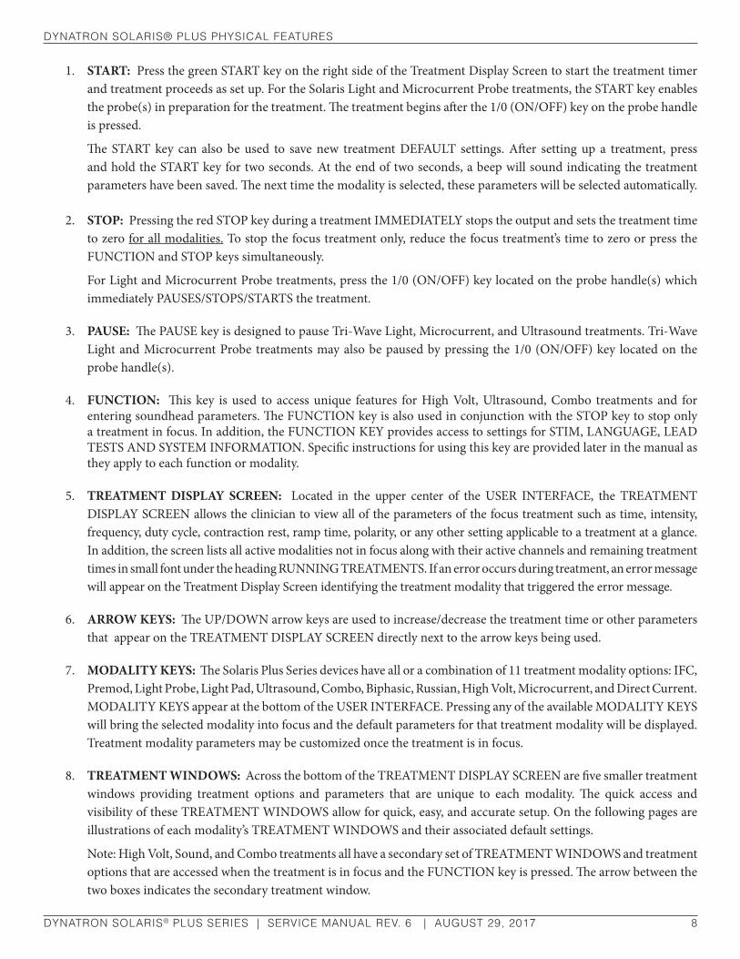
1. START: Press the green START key on the right side of the Treatment Display Screen to start the treatment timer and treatment proceeds as set up. For the Solaris Light and Microcurrent Probe treatments, the START key enables the probe(s) in preparation for the treatment. The treatment begins after the 1/0 (ON/OFF) key on the probe handle is pressed.
The START key can also be used to save new treatment DEFAULT settings. After setting up a treatment, press and hold the START key for two seconds. At the end of two seconds, a beep will sound indicating the treatment parameters have been saved. The next time the modality is selected, these parameters will be selected automatically.
2. STOP: Pressing the red STOP key during a treatment IMMEDIATELY stops the output and sets the treatment time to zero for all modalities. To stop the focus treatment only, reduce the focus treatment’s time to zero or press the FUNCTION and STOP keys simultaneously.
For Light and Microcurrent Probe treatments, press the 1/0 (ON/OFF) key located on the probe handle(s) which immediately PAUSES/STOPS/STARTS the treatment.
3. PAUSE: The PAUSE key is designed to pause Tri-Wave Light, Microcurrent, and Ultrasound treatments. Tri-Wave Light and Microcurrent Probe treatments may also be paused by pressing the 1/0 (ON/OFF) key located on the probe handle(s).
4. FUNCTION: This key is used to access unique features for High Volt, Ultrasound, Combo treatments and for entering soundhead parameters. The FUNCTION key is also used in conjunction with the STOP key to stop only a treatment in focus. In addition, the FUNCTION KEY provides access to settings for STIM, LANGUAGE, LEAD TESTS AND SYSTEM INFORMATION. Specific instructions for using this key are provided later in the manual as they apply to each function or modality.
5. TREATMENT DISPLAY SCREEN: Located in the upper center of the USER INTERFACE, the TREATMENT DISPLAY SCREEN allows the clinician to view all of the parameters of the focus treatment such as time, intensity, frequency, duty cycle, contraction rest, ramp time, polarity, or any other setting applicable to a treatment at a glance. In addition, the screen lists all active modalities not in focus along with their active channels and remaining treatment times in small font under the heading RUNNING TREATMENTS. If an error occurs during treatment, an error message will appear on the Treatment Display Screen identifying the treatment modality that triggered the error message.
6. ARROW KEYS: The UP/DOWN arrow keys are used to increase/decrease the treatment time or other parameters that appear on the TREATMENT DISPLAY SCREEN directly next to the arrow keys being used.
7. MODALITY KEYS: The Solaris Plus Series devices have all or a combination of 11 treatment modality options: IFC, Premod, Light Probe, Light Pad, Ultrasound, Combo, Biphasic, Russian, High Volt, Microcurrent, and Direct Current. MODALITY KEYS appear at the bottom of the USER INTERFACE. Pressing any of the available MODALITY KEYS will bring the selected modality into focus and the default parameters for that treatment modality will be displayed. Treatment modality parameters may be customized once the treatment is in focus.
8. TREATMENT WINDOWS: Across the bottom of the TREATMENT DISPLAY SCREEN are five smaller treatment windows providing treatment options and parameters that are unique to each modality. The quick access and visibility of these TREATMENT WINDOWS allow for quick, easy, and accurate setup. On the following pages are illustrations of each modality’s TREATMENT WINDOWS and their associated default settings.
Note: High Volt, Sound, and Combo treatments all have a secondary set of TREATMENT WINDOWS and treatment options that are accessed when the treatment is in focus and the FUNCTION key is pressed. The arrow between the two boxes indicates the secondary treatment window.

dynaTron solarIs® Plus PhysICal feaTures
DYNATRON SOLARIS® PLUS SERIES | SERVICE MANUAL REV. 6 | AUGUST 29, 2017 9
IFC (Interferential) Premod
Biphasic Russian
LT PROBE (Tri-Wave Light Probe) LT PAD (Tri-Wave Light Pad)
MC (Microcurrent) DC (Direct Current)
dynaTron solarIs® Plus PhysICal feaTures
DYNATRON SOLARIS® PLUS SERIES | SERVICE MANUAL REV. 6 | AUGUST 29, 2017 10
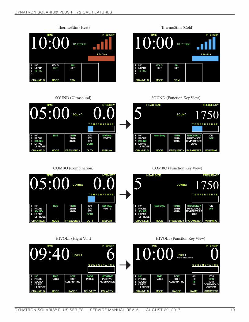
SOUND (Ultrasound)
HIVOLT (Hight Volt)
COMBO (Combination)
SOUND (Function Key View)
HIVOLT (Function Key View)
COMBO (Function Key View)
ThermoStim (Heat) ThermoStim (Cold)

dynaTron solarIs® Plus PhysICal feaTures
DYNATRON SOLARIS® PLUS SERIES | SERVICE MANUAL REV. 6 | AUGUST 29, 2017 11
9. TREATMENT WINDOW TOGGLE KEYS: TOGGLE KEYS are located below the five TREATMENT WINDOWS. Pressing the Toggle Key directly below a window allows one to choose an output channel, and select treatment parameters for the treatment in focus. A treatment is in focus when the name of the treatment appears in the center of the TREATMENT DISPLAY SCREEN and the name of the modality is highlighted green in the channels window.
10. CHANNELS WINDOW / CHANGING THE FOCUS TREATMENT
One of five TREATMENT WINDOWS, this window lists the available channels/jacks: 1,2,3,4, HV (High Volt, Probe (MultiStim), Sound, LT Pad or LT PD1(2) indicates Light Pad, and LT Probe or LT PB1(2) Light Probe. Some treatment jacks do not appear in the CHANNELS window until the accessory device is inserted into the Solaris Plus console, for example Light Probe, Light Pad, ThermoStim, and Sound.
The Channel Number/Indicator lights in the CHANNELS window identify which output channels/jacks are currently in use. The channel(s)/jack illuminated in GREEN indicates the focus treatment and the time, intensity, and other treatment parameters for that active treatment appear on the Treatment Display Screen. A Channel/Indicator illuminated in YELLOW identifies a channel/treatment is in use and delivering current, but is not in focus. The intensity, and treatment parameters are not displayed at this time (only one channel’s parameters may be displayed at a time). A treatment’s parameters may only be modified when the treatment is brought into focus. To bring a treatment into focus, press the CHANNELS TOGGLE key below the CHANNELS window to select a channel to be brought into focus. When the channel is in focus, the name will be illuminated GREEN. If a treatment that is active but not the focus treatment times-out, the text in the CHANNELS window will change from YELLOW to WHITE. A channel running in the background will change from YELLOW to ORANGE when the stim output is in “rest” mode (Russian or Biphasic).
11. TARGET PAD: The Solaris Plus TARGET feature is engineered to precisely pinpoint a patient’s pain. As the finger is glided across the TARGET touchpad, the patient identifies the point of greatest pain. When the TARGET point is identified, the finger is lifted from the Target Pad and the selected TARGET is locked in place. TARGET is available with Interferential or any four pad stim treatment.
dynaTron solarIs® Plus PhysICal feaTures
DYNATRON SOLARIS® PLUS SERIES | SERVICE MANUAL REV. 6 | AUGUST 29, 2017 12
12. CONDUCTANCE/TEMPERATURE BAR
Conductance.
The Solaris Plus devices continuously measure conductance during electrical Stim treatments for Interferential, Premod, and Microcurrent to ensure that the treatment outcome is optimal and to minimize the possibility of patient discomfort due to poor conductance and/or changes in current density. As conductance is measured, Solaris Plus displays the results in graph form on the CONDUCTANCE bar located on the right side of the TREATMENT DISPLAY SCREEN. Optimum conductance is displayed as the conductance bar flows RED - YELLOW- GREEN. GREEN indicating the best CONDUCTANCE. If the green bar only partially fills the graph area, the conductance is at a percentage of optimum. Lower INTENSITY may cause the bar to partially fill, but does not mean that the treatment is not effective. Below are some helpful definitions.
Conductance and Worn Electrodes.
Conductance is how readily electrical current is passed from the electrode to the skin surface during a treatment. Conductance affects current density. A worn electrode that does not conduct the current evenly over its entire surface will have “hot spots” where a greater amount of current flows through a smaller area which means the current density is higher at that point than elsewhere on the electrode. “Hot Spots” can lead to patient discomfort. Never risk patient comfort by using worn electrodes or lead wires.
Intensity.
The intensity level is a convenient incremental measurement. However, raising the intensity increases the current delivered to the patient but does not improve conductance.
Current Density.
Current density is the amount of current that passes through a given area of the electrode. Current density varies depending on the size of the electrode, the conductance, and intensity setting; and has an effect on patient comfort. With proper setup and good accessories, current is dispersed evenly over the entire surface of the electrode. The smaller the electrode, the greater the density of the current delivered through the area. To reduce current density and improve patient comfort, use larger electrodes, or lower the intensity setting, or both.
During a Microcurrent probe treatment, the graph is also useful in observing conductance changes since the goal of some Microcurrent treatments is to increase conductance (reduce resistance/impedance) at a given point.
If the number of green displayed segments begin to decrease on the graph during a treatment, it is important to determine the cause of the poor conductance. Remember with poor conductance you may inadvertently increase current density at a small point under the electrode and cause patient discomfort. Following are some considerations to insure proper conductance.
• Check to be sure electrodes are not worn or that self-adhesive electrodes have not lost their adhesiveness. These are the most common causes of poor current delivery. Both self-adhesive and carbon electrodes eventually lose their ability to conduct current effectively. See “Electrotherapy Usage Cautions” in this manual for recommended intensity settings and usage limits.
• Check to ensure the entire surface of the poly adhesive electrode is adhering.
• Self-adhesive electrodes do not require sterilization, however, electrodes should be clean and hydrated (see package instructions or “Self-Adhesive Electrodes” section of this manual).

dynaTron solarIs® Plus PhysICal feaTures
DYNATRON SOLARIS® PLUS SERIES | SERVICE MANUAL REV. 6 | AUGUST 29, 2017 13
• Check to be sure the snap adapters haven’t fallen off or that the lead wire has not become disconnected from the electrodes or the device.
• Make sure carbon electrodes have a secure connection with the pin ends of the leads. Over time the carbon electrodes may become too loose to use safely and the electrodes must be replaced.
• Check for corrosion on lead ends.
• Make sure carbon electrodes are adequately moistened and free from build-up to allow complete contact across the surface of the electrode.
• Observe the electrode placement. Some areas of the patient’s body conduct current better than others. In areas where resistance is high you may be unable to obtain optimum conductivity.
• Check the dryness of the patient’s skin. Dry skin does not conduct current well.
• Check to see if the electrodes do not adhere properly when a patient shifts position during a treatment. Worn electrodes could become loose and a significant change in conductance could result.
Temperature.
The Solaris Plus devices continuously measure temperature during a Light Probe, Light Pad, Ultrasound, and Combo Treatment. TEMPERATURE is indicated by the length of the Blue/Green indicator lights on the temperature bar. The longer the length of the colored bar, the higher the temperature. It is not uncommon to have the temperature bar move into the medium length ranges. If the temperature of an ultrasound treatment approaches the maximum level of 108° Fahrenheit (42.22° Celsius), the treatment is automatically PAUSED, output power stopped, and treatment time stops counting down. Following a cooling period, the treatment may be continued by pressing START.
Channels and Jacks
13. Front Panel Channels and High Volt Jack
Illustrated below are the output channels for delivering Interferential, Premodulated, Russian, Biphasic, and Microcurrent treatments. These channels are located on the front of the device. As you face the device, channels 1 and 2 are on the left, channels 3 and 4 are on the right with the dedicated High Volt jack for delivering High Volt Pad treatments in the middle. Three channel units (708 and 705) have channels 1, 2, and High Volt.
Front Panel Channels and Jack
dynaTron solarIs® Plus PhysICal feaTures
DYNATRON SOLARIS® PLUS SERIES | SERVICE MANUAL REV. 6 | AUGUST 29, 2017 14
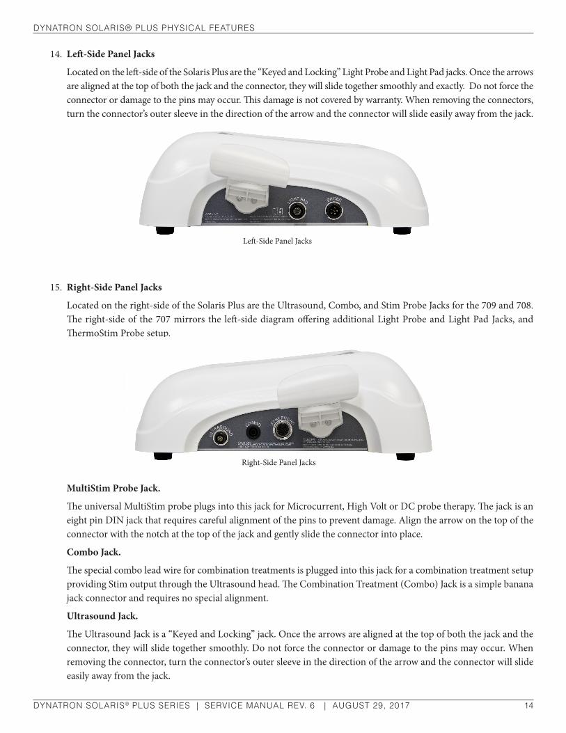
14. Left-Side Panel Jacks
Located on the left-side of the Solaris Plus are the “Keyed and Locking” Light Probe and Light Pad jacks. Once the arrows are aligned at the top of both the jack and the connector, they will slide together smoothly and exactly. Do not force the connector or damage to the pins may occur. This damage is not covered by warranty. When removing the connectors, turn the connector’s outer sleeve in the direction of the arrow and the connector will slide easily away from the jack.
15. Right-Side Panel Jacks
Located on the right-side of the Solaris Plus are the Ultrasound, Combo, and Stim Probe Jacks for the 709 and 708. The right-side of the 707 mirrors the left-side diagram offering additional Light Probe and Light Pad Jacks, and ThermoStim Probe setup.
MultiStim Probe Jack.
The universal MultiStim probe plugs into this jack for Microcurrent, High Volt or DC probe therapy. The jack is an eight pin DIN jack that requires careful alignment of the pins to prevent damage. Align the arrow on the top of the connector with the notch at the top of the jack and gently slide the connector into place.
Combo Jack.
The special combo lead wire for combination treatments is plugged into this jack for a combination treatment setup providing Stim output through the Ultrasound head. The Combination Treatment (Combo) Jack is a simple banana jack connector and requires no special alignment.
Ultrasound Jack.
The Ultrasound Jack is a “Keyed and Locking” jack. Once the arrows are aligned at the top of both the jack and the connector, they will slide together smoothly. Do not force the connector or damage to the pins may occur. When removing the connector, turn the connector’s outer sleeve in the direction of the arrow and the connector will slide easily away from the jack.
Left-Side Panel Jacks
Right-Side Panel JacksRight-Side Panel Jacks

dynaTron solarIs® Plus PhysICal feaTures
DYNATRON SOLARIS® PLUS SERIES | SERVICE MANUAL REV. 6 | AUGUST 29, 2017 15
16. Back Panel Jacks
a. Power 1/0 (ON/OFF) Switch. Located on the back of the unit this switch is labeled “1” and “0.” Set the switch to “1” for ON; set the switch to “0” for OFF.
b. Battery. This jack may be used to supply power to the device using an optional battery pack. More information about the optional battery operation is provided later in this manual.
c. SD Card Input. The SD Input provides a way for the Solaris Plus Devices to receive software updates quickly and easily. Complete instructions for updating the devices using an SD card are found in the “Technical” information section of the manual.
Current LimitThe Dynatron Solaris Plus devices continuously measure the actual current output during a treatment and limit the output current to the level indicated in “Technical Information” in this manual. As the intensity of a treatment is increased the current output is also increased.
When the maximum output current limit is reached, the device will immediately stop increasing the intensity and automatically reduce the intensity a few increments to prevent the possibility of patient discomfort. Simultaneously, the device will beep and one of the following CURRENT LIMIT WARNINGS will appear in the lower right-hand corner of the Treatment Display Screen. Following is a list of CURRENT LIMIT WARNINGS that may occur.
Back Panel Jacks
cb
a
NOTE: Patient Remote Stop. Adding the Remote Stop requires a custom order. The Patient Remote Stop Jack is located below the Light Probe holder. The remote stop is controlled by the patient during unattended therapy, allowing the patient to stop the treatment at any time. When the button on the remote stop cable is pressed, output for all Stim modalities and pad treatments is stopped. During Combo treatments, both Sound and Stim outputs are stopped.
Remember to treat at the patient’s comfort level. It is not important to reach a given intensity level. It is only important to set the treatment at a level that is comfortable to the patient. See “Electrotherapy Usage Cautions” in this manual for suggested intensity limits.

dynaTron solarIs® Plus PhysICal feaTures
DYNATRON SOLARIS® PLUS SERIES | SERVICE MANUAL REV. 6 | AUGUST 29, 2017 16
CURRENT LIMIT ERROR MESSAGES CAUSE
“Cannot start treatment with zero intensity” Intensity not set
error 101, error 111, error 120, error 130 “lead error: current too low!
Please check or replace your leads and pads!”lead issue; electrode issue
error 100, error 110, error 140 “lead error: high current delivery detected. adjusting intensity
to a safe limit. Please check leads. space electrodes further apart. ensure skin is dry between electrodes.”
lead shorted electrodes touching or too close
hot pack may be too moist
Most warnings will occur during the setup portion of a treatment. It would be rare to encounter a current limit warning during a patient treatment as reaching the current limit would require an intensity setting that is uncomfortable and intolerable to most patients. Below are some possible considerations for exceptions:
• The patient is unable to adequately feel the current and is unable; therefore, to report discomfort at the high intensity level.
• When using four large electrodes for a treatment, current is dispersed over a larger electrode surface area permitting a higher intensity setting without discomfort to the patient.
• For users who need to provide intensity levels above 50 mA (not available Japan or Canada), the default may be changed to 100mA: 1) Begin at the START UP SCREEN. 2) Press the FUNCTION KEY. 3) Use the toggle key under the MODE WINDOW to select the 100mA option and confirm your choice when prompted. Press STOP to return to the START UP SCREEN.
As the intensity is increased, ensure that the patient feels the current as expected. If the patient is unable to feel the current, the current could unintentionally be raised to a level much too high and risk causing unnecessary discomfort or possibly burn the patient. Keep the intensity very low if the patient has little or no feeling in the treatment area (see “Contraindica-tions, Warnings, and Precautions” in this manual). If you encounter the Current Limit Warnings, it may indicate that the patient cannot adequately feel the current. Reduce the intensity immediately.
A wide range of factors can cause the patient to lack sufficient feeling in the treatment area, including, but not limited to, pain control drugs, use of ice packs, neurological damage, etc.
Always consider these and other factors when delivering an electrotherapy treatment. Determine intensity settings based upon your medical expertise and judgment.
Error MessagesIf an error occurs during any active treatment, whether in or out of focus, the Solaris Plus will sound a beep. A white box with a red Error message will appear in the Time area of the Treatment Display Screen, if the treatment is in focus. If the treatment error is associated with a treatment that is not in focus, “ERR” will appear next to the active treatment listed on the left-hand side of the screen with other treatments that are currently running but not in focus. Pressing the modality key for the treatment indicated will bring that treatment into focus and details regarding the error will appear on the Treatment Display Screen.

dynaTron solarIs® Plus PhysICal feaTures
DYNATRON SOLARIS® PLUS SERIES | SERVICE MANUAL REV. 6 | AUGUST 29, 2017 17
Ultrasound Error Messages
ULTRASOUND ERROR MESSAGES CAUSE
“no soundhead connected, cannot setup ultrasound/combo treatment.” no soundhead attached
“soundhead is too hot! output has been disabled to allow cooling.” soundhead is too hot
“Caution: soundhead is getting hot!” soundhead is getting hot
“Thermistor on soundhead is broken! Please get soundhead replaced.” Thermistor on soundhead is broken
Lead Wires
Even with good care, lead wires will eventually develop breaks (open connections) simply from normal usage, and must be replaced about every six months. Damage can occur due to jerking or pulling on the wires, excessive bending or tight wrapping the wires, or running over the wire with a device cart. When setting up treatments, keep lead wires out of areas where a person could trip on them. When storing, lead wires should be loosely wrapped to prevent any kinking in the lead wire. Never use worn or damaged leads to treat a patient. Using faulty leads may result in injury to a patient.
DID YOU KNOW?
• Lead wires should be replaced at least every six months
• Carbon electrodes should be replaced approximately every six months
• Self-adhesive electrodes should be replaced after no more than 15 uses
• You should never use monitoring electrodes nor ordinary TENS electrodes with this device
• Some brands of electrodes are of very poor quality or are inappropriate for electrotherapy. Your patient may experience discomfort and even skin reaction due to poor distribution of current when using these electrodes
• Failure to replace worn lead wires and carbon electrodes or using cheap, poor quality electrodes are some of the most common causes of patient discomfort.

dynaTron solarIs® Plus PhysICal feaTures
DYNATRON SOLARIS® PLUS SERIES | SERVICE MANUAL REV. 6 | AUGUST 29, 2017 18
Test Leads DailyLead wires should be tested regularly to ensure they are functioning properly and safely. A simple test performed with the Dynatron Solaris Plus devices makes daily lead testing convenient. Damaged or worn leads should be discarded and replaced. Instructions for testing are provided below.
Remove Corrosion From Lead TipsLead tips will build up corrosion through use. The lead tips must be cleaned and kept free of corrosion in order to function correctly. To remove corrosion from lead tips, use steel wool to gently scrape off the corrosion. Take care not to scratch the metal plating of the tip during cleaning. If the tip’s metal surface becomes pitted or uneven, the lead must be replaced.
Testing LeadsTo test leads, perform the following steps daily.
1. Power on the Solaris Plus.
2. When the device has completed INITIALIZING, press the FUNCTION key located on the right side of the USER INTERFACE to activate the SETTINGS screen.
3. Make sure that LEAD TEST is illuminated GREEN in the MODE window.
4. Using the LEAD TEST TOGGLE KEY, select ON in the LEAD TEST window. ON will be illuminated GREEN.
5. Plug a lead into Channel 1 (no other channel is used for the lead test). Remove snap adapters, if applicable, from the leads.
6. Press START.
7. Hold the pins securely together, move the leads around, wiggle the cord, especially at the jack end of the cord. The numbers in the CONDUCTANCE window will begin to count up. The quality of the lead is represented on a rolling scale of 0 to 250. The higher the number the better the lead’s quality. A count of 200 or more indicates the lead is ready to be used. If the count registers under 100, the leads are probably bad and should be replaced.
8. After the test, remove the lead from Channel 1. If other leads need to be tested, plug in the next lead and test in the same way.
9. To exit the LEAD TEST function, press the STOP key.
WARNINGUNDER NO CIRCUMSTANCES SHOULD THE LEADS BE CONNECTED TO A PATIENT DURING THIS TEST!
dynaTron solarIs® Plus PhysICal feaTures
DYNATRON SOLARIS® PLUS SERIES | SERVICE MANUAL REV. 6 | AUGUST 29, 2017 19
Carbon ElectrodesCarbon electrodes provide an economical means of delivering electrotherapy to patients but should not be used with Microcurrent. This type of electrode lasts a long time and can be used again and again. However, if they are not properly cared for, these electrodes can fail to deliver the desired treatment and can present the possibility for injury to a patient. To ensure greatest safety and effectiveness with your treatments, follow these rules when using carbon electrodes.
1. Carbon electrodes must be well-moistened prior to treatment setup.
Dry carbon electrodes are very poor conductors of current and should NEVER be used. They may be moistened with either water or an electrolyte spray. Water is adequate for short treatments, but will evaporate too quickly for longer treatments. If water is used for longer treatments, you may need to interrupt the treatment and remoisten the electrodes. A special sponge fabric available with some carbon electrodes may be moistened well and used as a conductive medium (do not use ordinary sponges for this purpose). Do not use Ultrasound gel as a conductive agent with carbon electrodes.
If you use an electrolyte spray, this liquid may be diluted with equal amounts of distilled water, if desired. This reduces the amount of build-up on the electrodes yet usually provides adequate moistening of the electrodes.
2. Carbon electrodes must be free from any build-up.
If electrodes have a build-up from body oils or a moistening agent such as an electrolyte spray, conductivity is greatly impaired. If treatment is allowed to continue, intensity could be inhibited. When using carbon electrodes with any electrotherapy device, you must make sure conductivity is not impaired due to any type of build-up on the electrodes.
3. How to Clean Carbon Electrodes.
Carbon electrodes from Dynatronics may be cleaned using a mild soap and a small brush (such as a nail brush). To sterilize, alcohol may be used. They may also be sterilized in an Autoclave. Daily cleaning is recommended
If seeking a commercial cleanser/disinfectant, it is recommended that a product contain only the following active ingredients to avoid damage to the probe or pads:
NOTE: As you increase the intensity to higher levels during setup, if your patient feels a “biting” sensation or if the patient feels nothing, this indicates you are not getting adequate conductivity—the electrode may be too dry or is not moistened evenly across its entire surface. Stop the setup and correct the problem.
NOTE: The LEAD TEST should be used for testing patient lead wires only. This is not an accurate means of testing carbon electrodes. Contact Dynatronics Customer Service to arrange for free testing of carbon electrodes or for instructions for testing these electrodes.
dynaTron solarIs® Plus PhysICal feaTures
DYNATRON SOLARIS® PLUS SERIES | SERVICE MANUAL REV. 6 | AUGUST 29, 2017 20
OctylDecyl Dimethyl Ammonium Chloride
Dioctyl Dimenthyl Ammonium Chloride
Didecyl Dimenthyl Ammonium Chloride
Alkyl (C14 50%; C12 40%; C16 10
Dimenthyl Benzyl Ammonium Chloride
Other Ingredients not published
4. Carbon electrodes eventually wear out.
Do not assume you can safely use carbon electrodes indefinitely. Over time these electrodes will wear; and when worn, the amount of current delivered through the electrode will decrease and will be inconsistent over the surface of the electrode. As a general rule, carbon electrodes that are used regularly should be replaced at least every six months.
Do not take chances with patient safety! Discard worn carbon electrodes!
If you think that your carbon electrodes are showing wear, you can test them with an ohm meter. Good carbon electrodes should measure resistance between 40 and 200 ohms.
Self-Adhesive ElectrodesDynatronics’ self-adhesive electrodes are intended for multiple but patient specific use due to the danger of cross contamination. Improper use of the electrodes can decrease the life of the electrode and could even result in harm to your patient. The following instructions will help you achieve maximum usage from your electrodes while ensuring patient safety and comfort during treatment.
1. Make sure the electrode is adhering and making contact with the skin across the entire surface of the electrode. Electrodes will lose their adhesive quality when exposed to air, dust, dry skin, etc.
To Retain Adhesiveness:
• Electrodes should be stored in a tightly sealed pouch until used.
• The patient’s skin should be thoroughly cleaned and free from oils or flakiness prior to placing the electrodes.
To Restore Adhesiveness:
• Before a Treatment. Before placing the electrode on the patient, moisten the patient’s skin with a damp cloth using plain water, then apply the electrode to the skin.
• After a Treatment. Apply one or two drops of water to the adhesive side of the electrode using plain water, rub it lightly with fingertips, reapply the electrode to its plastic backing, and seal it tightly in its storage pouch. Do not use an electrolyte spray to remoisten self-adhesive electrodes as this substance can destroy the adhesive. Self-adhesive electrodes do not require sterilization.
dynaTron solarIs® Plus PhysICal feaTures
DYNATRON SOLARIS® PLUS SERIES | SERVICE MANUAL REV. 6 | AUGUST 29, 2017 21
• With this method of re-hydration, after a couple of hours electrodes can regain up to 90 per cent of their original adhesive quality.
2. NEVER use a self-adhesive electrode for more than 15 treatments (maximum).
3. NEVER USE STRAPS, WEIGHTS, or other devices to attach self-adhesive electrodes to the skin. If an electrode has lost its adhesive quality, you can use one of the methods given above to re-hydrate the adhesive, or you should discard the electrode. Using straps and weights with self-adhesive electrodes could have an unpredictable effect on the electrodes and could cause injury.
4. NEVER use monitoring electrodes such as ECG, or EMG, nor ordinary TENS electrodes.
5. If you see the “No Patient Current” screen message, or if you observe poor conductivity indicators, check the electrodes and lead wires for proper connection.

eleCTroTheraPy InforMaTIon and usage CauTIons
DYNATRON SOLARIS® PLUS SERIES | SERVICE MANUAL REV. 6 | AUGUST 29, 2017 22
Electrotherapy Information and Usage CautionsThe following general cautions are to be observed during Interferential, Premodulated, Russian, Biphasic, High Voltage, and Direct Current stimulation. For Microcurrent electrotherapy, see additional cautions in the Microcurrent Section of this manual.
Electrical stimulation, by its very nature, has the ability to irritate the patient’s skin. Certain precautions should be observed to assure maximum safety and comfort for patients. A patient’s tendency to have adverse reactions is dependent upon several factors. These factors are:
WARNING• NEVER turn the power ON or OFF while the unit is connected to the patient.
• Always STOP a treatment before removing or attaching electrodes or leads. Leads and electrodes must only be applied to the patient before a treatment is started.
• Never use worn or damaged leads or electrodes as these may result in injury to the patient.
• See the Contraindications, Warnings, and Precautions for Interferential and Premodulated treatments in this manual before administering a treatment.
• Additional warning from the Canadian Health and Welfare Department, Health Protection branch: WARNING: Thoracic applications are contraindicated. Cardiac fibrillation may occur if output current is 50mA RMS or greater for any output circuit. (For use in Canada and Japan, this device is limited to 50mA output).

eleCTroTheraPy InforMaTIon and usage CauTIons
DYNATRON SOLARIS® PLUS SERIES | SERVICE MANUAL REV. 6 | AUGUST 29, 2017 23
Current DensityThis is the amount of current being delivered to the patient divided by the area through which the current is being delivered (the surface area of the electrodes being used).
Electrode ConditionWorn or dried out electrodes cause the current to concentrate in small areas of the electrode instead being evenly distributed over the entire surface of the electrode. This has the effect of concentrating and increasing the current density into small areas.
Patient SusceptibilitySome patients’ skin is more sensitive to electrotherapy currents. This can cause a reaction similar to a heat rash.
Electrotherapy treatment can result in a rash, burn, or blister. The tendency to do this is dependent upon the factors listed above and can be minimized by applying the following guidelines:
1. Use only moderate current
It is not always necessary to raise the treatment intensity to just short of the patient’s pain threshold to achieve adequate results. Below is a chart comparing the size of the self-adhesive and carbon electrodes with their suggested maximum intensity levels.
For Biphasic or Russian stimulation treatments intended to effect a muscle contraction, it may sometimes be necessary to exceed these recommended limits to achieve the desired results. However, use caution when doing so to ensure that the patient can feel and can comfortably tolerate the electrical current. Also observe all other precautions in this section concerning leads and electrodes to ensure the higher intensity setting is not necessary as a result of defective accessories. In any case, do not exceed patient tolerance in setting the intensity. Consult published medical literature for more information about treatment protocols using each of these electrotherapy modalities.
Use as large an electrode as is practical for the application.
NOTE: The intensity settings should be considered maximum and not target intensities. These suggested settings apply to Interferential and Premodulated treatments. For High Voltage pulsed stimulation the intensity is displayed in volts; therefore, these suggested settings do not apply.
NOTE: The current density in a 1.25" square electrode is over FOUR TIMES the current density in a 1.75" by 3.75" electrode for the same intensity setting. Using larger electrodes allows current to be delivered over a larger area of the body keeping the current density as low as possible and minimizing the possibility for adverse reactions. Below are recommended intensities that correspond to electrode sizes.

eleCTroTheraPy InforMaTIon and usage CauTIons
DYNATRON SOLARIS® PLUS SERIES | SERVICE MANUAL REV. 6 | AUGUST 29, 2017 24
Interferential / Premodulatedelectrode size Maximum recommended Intensity
Carbon electrodes
3" round (7.62cm) 25 - 30
3" x 5" (7.62cm x 12.7cm) 30 - 40
self-adhesive electrodes
1.75" square (4.45cm) 10 - 15
1.75" x 3.75" (4.45cm x 9.53cm) 25 - 30
1.25" round (3.18cm) 10 - 12
2" round (5.08cm) 10 - 20
3" round (7.62cm) 25 - 30
When delivering combination Ultrasound and Stim treatments where the Stim current is delivered through the soundhead, the following are the recommended maximum Stim intensities (refers to Premodulated, Biphasic or Russian stimulation only):
Combination Treatmentultrasound head size Maximum recommended Intensity for electrotherapy
2 cm2 head 4 - 7
5 cm2 head 10 - 15
10 cm2 head 15 - 20
2. Ensure that the area on the patient’s skin where the electrode is to be placed is clean and free of all foreign matter.
Includes powders, perfumes, as well as body oils, dirt, and grime. Cleaning with an alcohol wipe should be adequate. Allow the alcohol to fully evaporate before applying the electrodes. Iontophoresis occurs with all electrical current therapies and can drive any of the above-surface contaminants below the epidural layer where an allergic reaction may occur.
3. Make sure the electrodes being used are in good condition.
The poly adhesive electrodes should have good adhesion over the entire surface area of the electrode. The area where the leads attach to the electrode (either through a lead or a snap) should not be damaged such that the connection to the foil backing behind the adhesive is broken. Carbon electrodes should be deep black and should be free of cracks in the electrode surface.
Any electrode which is suspect should be discarded. It’s not worth the price of an electrode to risk harming a patient.

eleCTroTheraPy InforMaTIon and usage CauTIons
DYNATRON SOLARIS® PLUS SERIES | SERVICE MANUAL REV. 6 | AUGUST 29, 2017 25
4. Some patients tend to be much more sensitive to electrotherapy treatments.
On patients with this tendency, treat with reduced intensity and/or shorter treatment times with possibly more frequent treatments, if required. Most reactions are localized and very short-lived, so limiting the exposure should minimize any potential for adverse reactions.
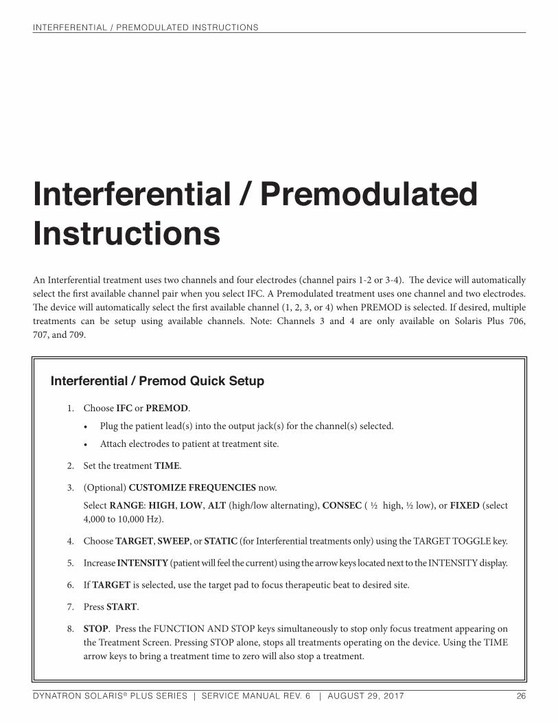
InTerferenTIal / PreModulaTed InsTruCTIons
DYNATRON SOLARIS® PLUS SERIES | SERVICE MANUAL REV. 6 | AUGUST 29, 2017 26
Interferential / Premodulated InstructionsAn Interferential treatment uses two channels and four electrodes (channel pairs 1-2 or 3-4). The device will automatically select the first available channel pair when you select IFC. A Premodulated treatment uses one channel and two electrodes. The device will automatically select the first available channel (1, 2, 3, or 4) when PREMOD is selected. If desired, multiple treatments can be setup using available channels. Note: Channels 3 and 4 are only available on Solaris Plus 706, 707, and 709.
Interferential / Premod Quick Setup
1. Choose IFC or PREMOD.
• Plug the patient lead(s) into the output jack(s) for the channel(s) selected.
• Attach electrodes to patient at treatment site.
2. Set the treatment TIME.
3. (Optional) CUSTOMIZE FREQUENCIES now.
Select RANGE: HIGH, LOW, ALT (high/low alternating), CONSEC ( ½ high, ½ low), or FIXED (select 4,000 to 10,000 Hz).
4. Choose TARGET, SWEEP, or STATIC (for Interferential treatments only) using the TARGET TOGGLE key.
5. Increase INTENSITY (patient will feel the current) using the arrow keys located next to the INTENSITY display.
6. If TARGET is selected, use the target pad to focus therapeutic beat to desired site.
7. Press START.
8. STOP. Press the FUNCTION AND STOP keys simultaneously to stop only focus treatment appearing on the Treatment Screen. Pressing STOP alone, stops all treatments operating on the device. Using the TIME arrow keys to bring a treatment time to zero will also stop a treatment.

InTerferenTIal / PreModulaTed InsTruCTIons
DYNATRON SOLARIS® PLUS SERIES | SERVICE MANUAL REV. 6 | AUGUST 29, 2017 27
Detailed Interferential / Premodulated Setup
1. IFC or PREMOD MODALITY keys
Press the IFC or PREMOD MODALITY keys to choose IFC (Interferential) or PREMOD (Premodulated). When you choose IFC, two channels are automatically selected: 1-2 or 3-4. When choosing PREMOD, the first available single channel is selected. Make sure the patient lead(s) is plugged into the correct jack(s) for the channel(s) selected. The default settings for the modality are automatically selected. If you wish to use the default settings, increase the intensity to the desired level, and press START.
Default Settings Time:..........................................10 minutes
Frequency Range: ...........High 80-150 Hz
Target (IFC): .......................................... On
If you wish to change or customize the treatment settings, proceed through the following steps:
2. Customize TIME
The default treatment time is displayed at 10:00 min. Use the TIME arrow keys to increase or decrease the treatment time.
3. Customize FREQUENCY (optional)
Default HIGH and LOW Frequency Settings
• HIGH range is 80 to 150 Hz.
• LOW range is 0 to 10 Hz.
• ALTERNATING range alternates every 30 seconds between HIGH and LOW, beginning with LOW.
• CONSECUTIVE HIGH/LOW. During the first half of the treatment time the High frequency range is delivered. During the second half of the treatment time the Low frequency range is delivered.
NOTE: Prior to increasing intensity, electrodes must be placed on the patient and the lead(s) attached to the device. Plug the lead(s) into the channel(s) the device selects for this treatment. Consult published sources for electrode placements, treatment settings, and treatment times. Make sure electrodes make good contact with the patient’s skin over the entire surface area of the electrode. Improper electrode contact may result in patient injury.
NOTE: ALTERNATING and HIGH/LOW options may be selected after pressing START. However, Consecutive and Fixed options must be selected before pressing START.

InTerferenTIal / PreModulaTed InsTruCTIons
DYNATRON SOLARIS® PLUS SERIES | SERVICE MANUAL REV. 6 | AUGUST 29, 2017 28
• FIXED. A FIXED treatment automatically defaults to a STATIC setting. Press the toggle key under MODE until FREQ is illuminated. A FIXED treatment can be set between 4,000 and 10,000 KHz. Selections progress from 4,000 KHz to 10,000 KHz in 1,000 KHz increments. Once the FIXED rate is set, return to the TIME display by using the MODE toggle key.
The default High and Low frequency settings may be changed for a single treatment if desired, or new default settings may be saved to apply to all future treatment setups.
• Press the toggle key under the MODE display. Select FREQ (Frequency).
• Press the toggle key under the RANGE display. Select a HIGH or LOW frequency range.
• The HIGH Frequency will appear on the left-hand side of the Treatment Display Screen. The LOW Frequency will appear on the right-hand side of the Treatment Display Screen. Changes to the upper and lower limits are made using the arrow keys to the side of each displayed setting. If you set both displays to the same value, the treatment will be delivered at that single frequency rather than sweep through a frequency range.
• After pressing START, frequency settings will remain in effect for the duration of the treatment. If you save defaults during this treatment, the new frequency settings you have entered become the defaults for this modality. However, if you do not save the new settings, the unit will return to the current default settings for the next treatment.
• To SAVE these CUSTOM FREQUENCY settings, hold the START key down until a beep sounds. Once saved, these settings will be used on all IFC or Premod treatments that follow.
• Press the toggle key under the MODE display to return to the TIME display, After 10 seconds with no key presses, the Time display will automatically return.
4. Choose TARGET, SWEEP, or STATIC (for Interferential only)
Using the toggle key located under the TARGET display make your selection from the three available options.
TARGET. Pinpoint the treatment site delivering the full Interferential current where it is needed.
NOTE: Make any desired changes to the treatment time before selecting Consecutive. Treatment time changes made after selecting Consecutive will cause the treatment to revert to an ALTERNATING HIGH/LOW treatment.
NOTE: If INTENSITY has been set during the setup of a FIXED treatment option and a change is made to any other treatment option, INTENSITY will automatically return to “0.”
NOTE: The intensity must be set before using the Target Pad so the patient will be able to indicate when the treatment site is found. Also remember, an injured area will often be more sensitive to the current delivered. Therefore, an intensity setting that is comfortable to the patient at first may feel uncomfortable when the treatment site is found using the TARGET PAD. If necessary, reduce the intensity to the patient’s comfort level.

InTerferenTIal / PreModulaTed InsTruCTIons
DYNATRON SOLARIS® PLUS SERIES | SERVICE MANUAL REV. 6 | AUGUST 29, 2017 29
SWEEP. The interferential current randomly sweeps the treatment area within the electrodes allowing the general area to be bathed with Interferential current.
STATIC. The interferential current focuses only on the point where the current between electrodes intersects as it follows the path of least resistance.
5. INTENSITY
Press the UP/DOWN arrow keys located next to the INTENSITY display on the right-hand side of the Treatment Screen. When the INTENSITY is increased, current to the patient begins. NOTE: The CONDUCTANCE BAR GRAPH will be operable at this time.
Before selecting the intensity setting for an individual patient, see “Electrotherapy Information and Usage Cautions” in this manual for recommended intensity settings. Also see the section of this manual entitled “Contraindications, Warnings, and Precautions” for specific precautions when treating any conditions contributing to loss of sensation, or any time the patient cannot feel the electrical stimulation.
6. Press START
When you press start, the treatment timer in the TIME display window begins counting down and the treatment proceeds. Remember to set the intensity before pressing START.
7. SAVE DEFAULTS
If the treatment you have just set up is a frequently used, you can save the treatment parameters as new defaults by pressing and holding the START key until a beep sounds indicating the treatment parameters have been saved. The next time you select the modality, these parameters will be selected automatically.
8. MODIFY SETTINGS
Treatment settings can be modified while the treatment is in progress except for a CONSECUTIVE HIGH/LOW treatment. If the TIME setting on a CONSECUTIVE HIGH/LOW treatment is altered, the treatment will be aborted and default to an ALTERNATING HIGH/LOW treatment.
• FREQUENCY RANGE. Use the Range Toggle key to select a different frequency option (High, Low, Alternating High/Low, Consecutive High/Low, or Fixed). Fixed Frequency and Consecutive High/Low cannot be selected after treatment is started.
• TARGET/SWEEP/STATIC. Use the Target Toggle key to select Target, Sweep, or Static (for IFC only).
• TIME. Use the Time Arrow keys to increase or decrease the treatment time.
• INTENSITY. Use the Intensity Arrow keys to increase or decrease the intensity.
• TARGET. Relocate the treatment site by touching the TARGET PAD at any time during the treatment when TARGET has been selected.

InTerferenTIal / PreModulaTed InsTruCTIons
DYNATRON SOLARIS® PLUS SERIES | SERVICE MANUAL REV. 6 | AUGUST 29, 2017 30
9. STOP.
When the treatment time has elapsed, the current to the patient stops and a tone sounds signaling the end of a treatment. Treatments in progress may be stopped at any time using one of the following methods.
Stop One Treatment Only. Press and hold the FUNCTION key and press STOP. This stops only the treatment in focus.
Stop All. Press the STOP key. All treatments at all channels will stop.
Stop Time. Reduce the treatment time using the Time arrow key. The output at the selected channel is stopped, and the device then displays the parameters for the next treatment that remains in progress (if there is an active treatment).

InTerferenTIal and PreModulaTed ModalITy InforMaTIon
DYNATRON SOLARIS® PLUS SERIES | SERVICE MANUAL REV. 6 | AUGUST 29, 2017 31
Interferential and Premodulated Modality Information
Interferential (Quadpolar) TherapyInterferential therapy uses four electrodes to deliver two currents, one current with a constant frequency of 4000 Hz and the other current with a variable frequency of 4000 to 4150 Hz. The paths of these two currents cross resulting in a “beat” that produces the therapeutic frequency at the treatment site.
The resulting frequency is between 1 and 150 Hz. An example of wave forms representing these currents is illustrated here.
In the Interferential mode, two output jacks (Channels 1 and 2, or 3 and 4) are utilized with four electrodes placed in a crisscross fashion, “bracketing” the treatment site. The output from Channel 1 (or Channel 3) is the constant 4000 Hz wave, while the output of Channel 2 (or Channel 4) is the variable 4000 to 4150 sine wave.
The “beat” phenomenon. Two waves of different frequencies over 4000 Hz, combine to produce a beat which is between 1 and 150 Hz.
Stimulation produced by 4 electrodes.

InTerferenTIal and PreModulaTed ModalITy InforMaTIon
DYNATRON SOLARIS® PLUS SERIES | SERVICE MANUAL REV. 6 | AUGUST 29, 2017 32
Premodulated (Bipolar) TherapyPremodulated therapy utilizes one output jack and two electrodes. The current delivered is a composite wave form. In order to produce this composite current, two Frequencies are “mixed” within the device prior to output. One frequency is 4000 Hz while the second frequency covers a range between 4000 to 4150 Hz.
With the Dynatron Solaris Plus devices, any of the four channels may be used simultaneously to deliver up to four separate, independent Premodulated treatments. A crisscross electrode setup pattern should not be used when setting up multiple Premodulated treatments. Note that a Premodulated treatment usually requires a lower intensity setting than an Interferential treatment since current is dispersed to only two electrodes rather than four (a smaller total coverage area means greater current density at the treatment site).
TargetThe Dynatronics’ TARGET (available for Interferential treatments only) simplifies placing the interferential beat directly on the treatment site. The movement of the finger on the Target paid along with the feedback supplied by the patient allows the user to place the full force of the interferential “beat” directly on the treatment site regardless of conductance variations caused by differences in human tissue (skin, muscle, bone, etc.) that, without Target, make placing the Interferential “beat” a guessing game. Target eliminates the need to move the electrodes to achieve the desired result.
In the diagram the electrodes are placed in a position to treat a point directly in the center of the electrodes. But the center of interference actually occurs at another point. In these illustrations the point of interference is shown in a cloverleaf shape as Interferential treatment affects a cloverleaf-shaped area. Using the Target pad, the point of interference in easily moved to the desired treatment area. Other devices increase current at one channel while decreasing it at the other. This merely rotates the treatment. The center of interference does not move.
Why Is Target Better?With Target, the voltage output from both channels remains equal at all times; so wherever the treatment is applied, a full, deep Interferential beat occurs. Other devices attempt to achieve this effect by increasing the current from one channel while decreasing the current from the other channel. This method only rotates the cloverleaf-shaped area, but the center of interference does not move. In addition, the depth of the beat is reduced.
Normal Interferential currents cross at a point between electrodes. It is difficult to guess where they will cross as shown in the left diagram. With Target, you move the point of interference without moving electrodes (as shown in the diagram on the right)—just press the touch pad.
Other devices increase current at one channel while decreasing it at the other. This merely rotates the treatment. The center of interference does not move.

InTerferenTIal and PreModulaTed ModalITy InforMaTIon
DYNATRON SOLARIS® PLUS SERIES | SERVICE MANUAL REV. 6 | AUGUST 29, 2017 33
Target SweepThe Sweep option literally moves the point of interference inward and outward in a somewhat spiral pattern, bathing about 80 percent of the area within the electrodes with the Interferential current. Sweep utilizes the Target feature and moves the point of interference to cover a wider treatment area while still retaining the full Interferential beat. Sweep bathes a larger area with the Interferential current.
Interferential Electrode PlacementWhen performing Interferential therapy with a two-channel or four-electrode setup, it is important to arrange the electrodes in a crisscross manner so the current from one channel will intersect with the current from the second channel at the point where treatment is to be delivered. Consult published literature for electrode placements for specific sites and conditions.
Interferential / Premodulated Default SettingsThe following default settings are set by the manufacturer and are selected when you select IFC or PREMOD. You may change these defaults to your own preferred settings.
Interferential Default Settings• High 80-150 Hz
• Target
• The first available channel pair (1-2 or 3-4)
• Time: 10 minutes
• Frequency Ranges: High 80-150 Hz; Low 0-10 Hz
Premodulated Default Settings• High 80-150 Hz
• Target
• The first available channel pair (1 through 4)
• Time: 10 minutes
• Frequency Ranges: High 80-150 Hz; Low 0-10 Hz
• Interferential/Premodulated Therapy: 4000 Hz sine wave frequency modulated by a 4000 to 4150 Hz variable frequency sine wave of equal amplitude
Interferential Electrode Placement
bIPhasIC / russIan InsTruCTIons
DYNATRON SOLARIS® PLUS SERIES | SERVICE MANUAL REV. 6 | AUGUST 29, 2017 34
Biphasic / Russian InstructionsIn the Russian and Biphasic Stimulation modes the output of the device is a pulsed sinusoidal wave. Solaris Plus allows the operator to choose a muscle contraction/rest cycle that is most suited for the individual patient and for the desired treatment. Once the cycle is chosen, each muscle-stimulating burst is followed by a rest cycle. See “Russian/Biphasic Parameters” in this manual for further discussion of pulse rate and duration, and illustrations showing the segments of the Russian Stimulation cycle and the Biphasic Stimulation cycle.
Solaris Plus provides four treatment options in Russian and Biphasic Stimulation: Normal, Reciprocal, Co-Contraction, and Custom. After deciding which treatment is to be used, attach the appropriate number of leads required to set up the treatment.
NORMAL: Use one channel with one lead wire (two electrodes). Place the electrodes so as to treat through the muscle. The contraction/rest cycle is selected from an option list of 10/10, 10/30, 10/50, CONT (continuous/no rest cycle), and Custom. Each time period is indicated in seconds. For example, 10/30 indicates 10 seconds of stimulation with 30 seconds of rest. The continuous duty cycle is not recommended for electrical muscle stimulation, but may be used for settings that are intended to effect results other than a muscle contraction.
CO-CONTRACTION: Use two channels and two lead wires (four-electrodes) for this treatment. Each pair of electrodes is placed over a different muscle group. This treatment fires the two muscle groups simultaneously—contraction and rest cycles for both treatment areas occur at the same time. Two channels are required (1-2 or 3-4). Note: 3-4 are available only on the Solaris Plus 706, 707, and 709.
RECIPROCAL: Use two channels and two lead wires (four electrodes) for this treatment. The reciprocal muscle stimulation fires two muscle groups (such as reciprocal flexors/extensors) one after the other. For example, with a duty cycle of 10/30, the device would deliver stimulation for 10 seconds to the first muscle, followed by 10 seconds of stimulation to the reciprocal muscle. A 30-second rest time follows each stimulation. The timing of the two cycles will overlap (the first muscle group is stimulated after a 30-second rest, even though the second muscle group is 20 seconds into its rest cycle). The Continuous contraction/rest cycle is not available for Reciprocal treatments. Two channels are required (1-2 or 3-4). Note: 3-4 are available only on the Solaris Plus 706, 707, and 709.
CUSTOM CONTRACTION: The Custom Contraction/Rest cycle feature allows the treatment to be customized by selecting from a Custom Contraction ON time (1 to 60 seconds), and an OFF time (1 to 90 seconds). Treatments can be customized by using the following steps:

bIPhasIC / russIan InsTruCTIons
DYNATRON SOLARIS® PLUS SERIES | SERVICE MANUAL REV. 6 | AUGUST 29, 2017 35
1. Press the CONT/REST toggle key. Select CUSTOM.
2. Press the MODE toggle key. Select CUST C/R (Custom Contraction Rest).
3. Press TREATMENT toggle key. Select Normal, Co-Cont, Recip.
4. Using the RAMP toggle key, select RAMP time (.05, 1.0, 1.5, 2.0).
5. Set CUSTOM CONTRACTION using the arrow keys on the left-side of the Treatment Display Screen (1-60 sec.)
6. Set CUSTOM REST using the arrow keys on the right-side of the Treatment Display Screen (1-90 sec.). The REST time can be set to a minimum of one second.
7. Press START.
Biphasic / Russian Quick Setup
1. Choose BIPHASIC or RUSSIAN.
2. Choose the TREATMENT (Normal, Co-contraction, or Reciprocal using the TREATMENT toggle key). Plug the patient lead(s) into the output jack(s) for the channel(s) selected.
3. Choose the CONTRACTION/REST times by pressing the CONTRACTION/REST toggle key.
4. Choose the RAMP setting by using the RAMP toggle.
5. Change the treatment TIME, by pressing the UP/DOWN TIME ARROW keys, if desired.
6. Change the PULSE and DURATION. Using the MODE toggle key select RATE/DUR (rate/duration).
• Press the PULSE RATE arrow keys to change the PULSE RATE
• Press the PULSE DURATION arrow keys to change the PULSE DURATION
7. Press the MODE toggle key to return to the TIME display window.
8. Raise the INTENSITY to the desired level by pressing the INTENSITY ARROW keys on the right-side of the Treatment Screen.
9. For co-contraction or reciprocal treatments, set the intensity for the first channel. Press START. The device will automatically select the second channel. Set the intensity for the second channel.
10. Press START.
11. STOP. Press the FUNCTION and STOP keys simultaneously to stop only the focus treatment appearing in the Treatment Screen. Pressing STOP alone, stops all treatments operating on the device. Using the TIME arrow keys to bring treatment time to zero will also stop a treatment.

bIPhasIC / russIan InsTruCTIons
DYNATRON SOLARIS® PLUS SERIES | SERVICE MANUAL REV. 6 | AUGUST 29, 2017 36
Detailed Biphasic / Russian SetupIf you do not understand the terms contraction, rest, ramp time, pulse duration, or pulse rate; consult the diagrams in the section of this manual entitled “Biphasic / Russian Parameters.”
1. Press the BIPHASIC or RUSSIAN
When you select this modality, the default settings are automatically selected. If you wish to use the default settings, you can now increase intensity to the desired level and press START.
Default Setting Mode............................................... Normal
Cont/Rest Time ................................. 10/30
Time ..........................................10 minutes
Ramp Time .................................... 0.5 sec.
If you wish to change the treatment settings, proceed through the following steps:
2. Choose the TREATMENT.
Use the TREATMENT toggle key to select NORMAL, CO-CONT (Co-contraction), or RECIP (Reciprocal). Connect the patient lead wire(s) to the channel(s) selected.
3. CONTRACTION/REST
Cycle Times Using the CONT/REST toggle key, choose the CONTRACTION/REST cycle times. Available options include 10/10, 10/30, 10/50, Continuous, and Custom. The setting of 10/30, for example, means a 10-second contraction time followed by a 30-second rest time. Note that you may not select Continuous cycle for a Reciprocal treatment. The Continuous duty cycle is not recommended for electrical muscle stimulation, but may be used for settings that are intended to effect results other than a muscle contraction.
4. Choose the RAMP Setting (does not affect Continuous treatments).
Press the RAMP TOGGLE key one or more times to select the desired ramp time. Available options include .5, 1.0, 1.5, and 2.0 seconds. The ramp time is applied to both the start and to the end of the contraction time. The ramp time is in addition to the contraction time itself.
5. Change the treatment TIME (optional).
The default time is displayed. Use the TIME arrow keys to increase or decrease the treatment time.

bIPhasIC / russIan InsTruCTIons
DYNATRON SOLARIS® PLUS SERIES | SERVICE MANUAL REV. 6 | AUGUST 29, 2017 37
6. Change the PULSE DURATION and/or PULSE RATE (optional)
Press the MODE toggle key to select RATE/DUR (Pulse Duration). The pulse DURATION (width) and RATE may be modified for each channel pair (1-2 and 3-4).
Press the PULSE RATE arrow keys to the left-side of the Treatment Screen to change the PULSE RATE. Press the PULSE DURATION arrow keys to the right-side of the Treatment Screen to change the PULSE DURATION. Press the MODE toggle key and select TIME to return the TIME display. However, if you make no key presses for 10 seconds, the display automatically returns to the TIME display. The ranges and default settings for pulse duration (width) and pulse rate are listed later in this section.
7. Raise the INTENSITY to the desired level.
Set the intensity by pressing the INTENSITY arrow keys located on the right-side of the Treatment Display Screen. Increasing the intensity sends current directly to the patient. Intensity can be decreased by pressing the down arrow key.
Before selecting the intensity setting for an individual patient, see section entitled “Electrotherapy Usage Cautions” for recommended intensity settings. Also see the section of this manual entitled “Contraindications, Warnings, and Precautions” for specific precautions when treating any conditions contributing to loss of sensation, or any time the patient cannot feel the electrical stimulation.
The intensity, pulse rate, and pulse duration must all be considered together when setting up the treatment as all three factors affect patient comfort. It may be necessary to adjust one or more of these parameters somewhat after the initial settings are selected to find the best settings for a given treatment and patient.
8. For co-contraction or reciprocal treatments, select the SECOND CHANNEL and set the INTENSITY.
Intensity is set for each channel separately. For co-contraction or reciprocal treatments, Set the intensity for the first channel. Press START. The device will automatically select the second channel. Set the intensity for the second channel. When setting intensity, only the channel with the solid GREEN light is affected. The first channel will be illuminated in YELLOW.
9. Press START
When you press START the treatment timer begins counting down. If the intensity is not set before pressing START, the treatment will not begin until the intensity is set. For Reciprocal and Co-contraction treatments, the intensity must be set for each channel separately.
10. SAVE DEFAULTS
If this treatment setup is the most common Biphasic or Russian treatment setup you use, save the treatment parameters as your defaults. After setting up the treatment, press and hold the START key until a tone sounds indicating the treatment parameters have been saved. The next time you select this modality, the saved parameters will be selected automatically.
11. MODIFY Settings
While the treatment is in progress, the treatment settings can be modified. Carefully observe the channel indicator lights when modifying a treatment. When a channel’s light is illuminated GREEN, the current treatment parameters for that channel are displayed. Any changes made to the parameters will affect only the channel that is illuminated in GREEN. Use the toggle key to display the parameters of another channel in order to modify parameters.
bIPhasIC / russIan InsTruCTIons
DYNATRON SOLARIS® PLUS SERIES | SERVICE MANUAL REV. 6 | AUGUST 29, 2017 38
During a Biphasic or Russian treatment you may make the following modifications:
• CONTRACTION/REST cycle.
• RAMP TIME
• TREATMENT TIME
• RATE/DURATION (not available for Reciprocal treatments nor when two “Normal” treatments are running simultaneously on a channel pair—CH 1-2 or 3-4).
• INTENSITY (separately for each channel)
12. STOP
When the treatment time has elapsed, the current to the patient stops and a tone sounds signaling the end of a treatment. Treatments in progress may be stopped at any time using one of the following methods.
Stop One Treatment Only. Press and hold the FUNCTION key and press STOP. This stops only the treatment in focus.
Stop All. Press the STOP key. All treatments at all channels will stop.
Stop Time. Reduce the treatment time using the Time arrow key. The output at the selected channel is stopped, and the device then displays the parameters for the next treatment that remains in progress (if there is an active treatment).
bIPhasIC / russIan ModalITy InforMaTIon
DYNATRON SOLARIS® PLUS SERIES | SERVICE MANUAL REV. 6 | AUGUST 29, 2017 39
Biphasic / Russian Modality Information
Russian StimulationWith Russian Stimulation mode, the output of the device is a 2500 Hz sinusoidal wave. Russian stimulation currents produce strong muscle contractions.
The Dynatron Solaris Plus devices allows complete control over all the parameters of the Russian Stimulation treatment. Three treatment modes include Normal for firing one muscle, Reciprocal for firing two different muscles at different times, and Co-contraction for firing two different muscles simultaneously. Choose a muscle contraction/relaxation cycle from options of 10/10 (ten seconds on and ten seconds off), 10/30, 10/50, Continuous, and Custom cycles. The Normal mode requires use of just one output jack (Channel 1, 2, 3, or 4). The Reciprocal and Co-Contraction modes utilize a channel pair (Channels 1-2 or 3-4).
NOTE: The continuous duty cycle is not recommended for electrical muscle stimulation, but may be used for settings that are intended to affect other results than a muscle contraction. Pulse rate, the pulse duration, and the ramp time can all be modified from their default settings.
Biphasic StimulationThe Biphasic stimulation is similar to Russian stimulation in the parameters that are selected and in the available options. It differs from Russian stimulation in the pulse duration and rate ranges (see parameters below). Additionally, the Biphasic pulse includes just one cycle (one positive phase and one negative phase) per pulse.
Biphasic / Russian Parameters and DefaultsThe default settings and the available ranges for Biphasic and Russian are as follows:
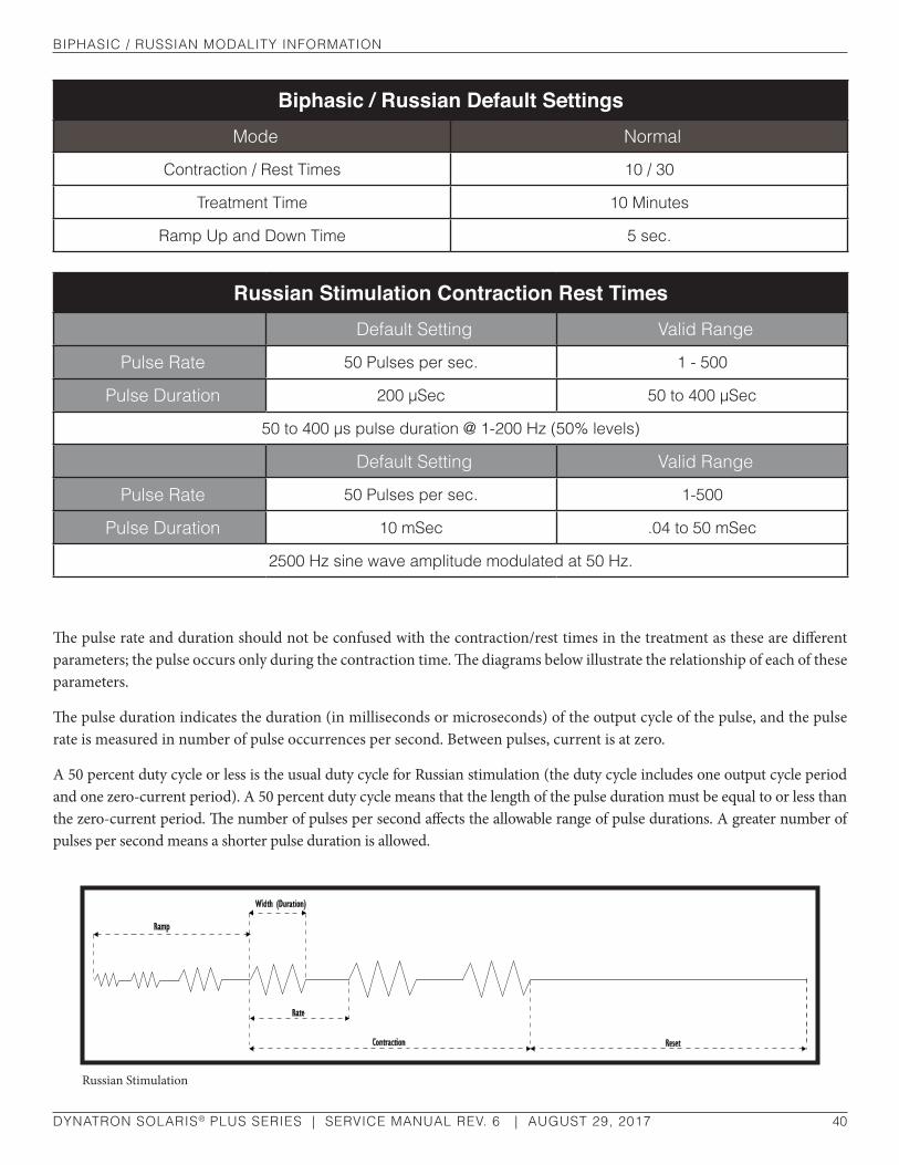
bIPhasIC / russIan ModalITy InforMaTIon
DYNATRON SOLARIS® PLUS SERIES | SERVICE MANUAL REV. 6 | AUGUST 29, 2017 40
Biphasic / Russian Default SettingsMode normal
Contraction / rest Times 10 / 30
Treatment Time 10 Minutes
ramp up and down Time 5 sec.
Russian Stimulation Contraction Rest Timesdefault setting Valid range
Pulse rate 50 Pulses per sec. 1 - 500
Pulse duration 200 µsec 50 to 400 µsec
50 to 400 µs pulse duration @ 1-200 hz (50% levels)
default setting Valid range
Pulse rate 50 Pulses per sec. 1-500
Pulse duration 10 msec .04 to 50 msec
2500 hz sine wave amplitude modulated at 50 hz.
The pulse rate and duration should not be confused with the contraction/rest times in the treatment as these are different parameters; the pulse occurs only during the contraction time. The diagrams below illustrate the relationship of each of these parameters.
The pulse duration indicates the duration (in milliseconds or microseconds) of the output cycle of the pulse, and the pulse rate is measured in number of pulse occurrences per second. Between pulses, current is at zero.
A 50 percent duty cycle or less is the usual duty cycle for Russian stimulation (the duty cycle includes one output cycle period and one zero-current period). A 50 percent duty cycle means that the length of the pulse duration must be equal to or less than the zero-current period. The number of pulses per second affects the allowable range of pulse durations. A greater number of pulses per second means a shorter pulse duration is allowed.
Russian Stimulation

bIPhasIC / russIan ModalITy InforMaTIon
DYNATRON SOLARIS® PLUS SERIES | SERVICE MANUAL REV. 6 | AUGUST 29, 2017 41
If a given Russian stimulation treatment has a 50 percent duty cycle, this means the output cycle is continuously repeating for half of the pulse duration (see “Rate” in the diagram above) followed by a zero-current period for the other half of the pulse duration.
Biphasic stimulation differs from Russian stimulation in the pulse duration (width) and rate ranges, as explained above. In addition, the Biphasic pulse includes just ONE output cycle per pulse. One pulse cycle (including one positive phase and one negative phase) occurs, followed by a zero-current period.
The pulse rate and duration (width) may be modified during setup of a Russian or Biphasic Stimulation treatment or may be modified while a treatment is in progress.
Biphasic Stimulation
When modifying the pulse rate and duration (width) for a treatment in progress, modify the intensity as well, as all three of these parameters will affect delivered energy and patient comfort.

hIgh VolT InsTruCTIons
DYNATRON SOLARIS® PLUS SERIES | SERVICE MANUAL REV. 6 | AUGUST 29, 2017 42
High Volt InstructionsHigh Volt electrical stimulation is a pulsed DC current with pulse durations in the microsecond range and pulse rates ranging from 1 to 200 Hz, with peak amplitude of up to 500 Volts. The Solaris Plus Series devices deliver High Volt utilizing a twin-peak monophasic waveform.
High Volt treatments may be delivered using electrodes or the optional MultiStim probe. The device provides a dedicated channel for High Volt electrodes treatment (HV) and a separate dedicated STIM PROBE JACK for probe treatments. During High Volt treatments, the Solaris Plus device’s other output channels (1-2-3-4) remain available for other simultaneously stim treatments. Note, the MultiStim probe is not available on the 707 model.
High Volt Electrode SetupThis treatment setup utilizes a standard lead wire with two electrodes; an active and a dispersive electrode. The size of the dispersive electrode is recommended to be double the area of the active electrode. If desired, the active output of the lead wire may be bifurcated by using an optional bifurcated extension (Part no. 7B0077) to attach additional active electrodes. However, the combined total area of the active electrodes should be no more than half the area of the single dispersive (passive) electrode, as illustrated.
It is best to use a lead that is marked to show polarity. The active electrode is connected to the positive output. The dispersive electrode is connected to the output end that is marked “HV Dispersive” (-). If desired, a bifurcated lead extension may be attached to the positive (HV Active) end of the lead wire, allowing two active electrodes to be used. In this case, High Volt Electrode Setup
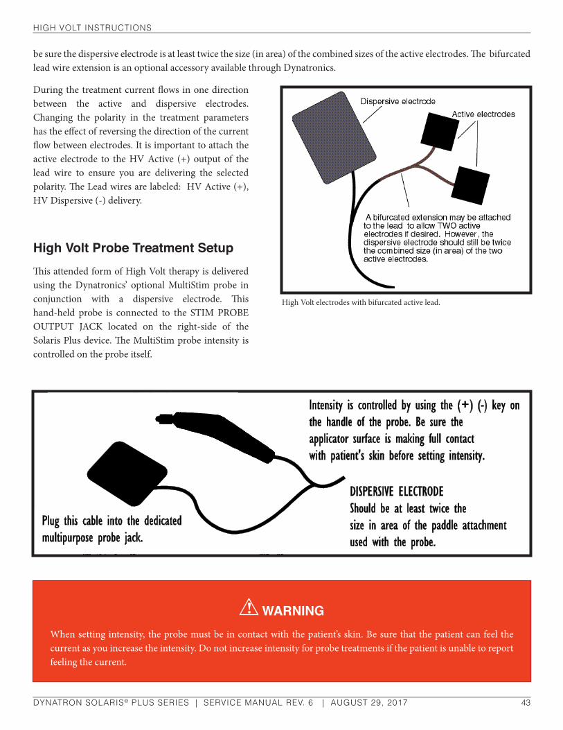
hIgh VolT InsTruCTIons
DYNATRON SOLARIS® PLUS SERIES | SERVICE MANUAL REV. 6 | AUGUST 29, 2017 43
be sure the dispersive electrode is at least twice the size (in area) of the combined sizes of the active electrodes. The bifurcated lead wire extension is an optional accessory available through Dynatronics.
During the treatment current flows in one direction between the active and dispersive electrodes. Changing the polarity in the treatment parameters has the effect of reversing the direction of the current flow between electrodes. It is important to attach the active electrode to the HV Active (+) output of the lead wire to ensure you are delivering the selected polarity. The Lead wires are labeled: HV Active (+), HV Dispersive (-) delivery.
High Volt Probe Treatment SetupThis attended form of High Volt therapy is delivered using the Dynatronics’ optional MultiStim probe in conjunction with a dispersive electrode. This hand-held probe is connected to the STIM PROBE OUTPUT JACK located on the right-side of the Solaris Plus device. The MultiStim probe intensity is controlled on the probe itself.
High Volt electrodes with bifurcated active lead.
WARNINGWhen setting intensity, the probe must be in contact with the patient’s skin. Be sure that the patient can feel the current as you increase the intensity. Do not increase intensity for probe treatments if the patient is unable to report feeling the current.

hIgh VolT InsTruCTIons
DYNATRON SOLARIS® PLUS SERIES | SERVICE MANUAL REV. 6 | AUGUST 29, 2017 44
Detailed High Volt Setup
1. Press the HI VOLT key.
The High Volt channel and the default settings for High Voltage electrode pulsed stimulation are automatically selected. Using the dedicated High Volt (HV) channel attach leads and place electrodes on the patient now. For a
High Volt Quick Setup
1. Press HI VOLT.
Electrode Treatment
• Plug in lead wire to the HIGH VOLT OUTPUT JACK (HV).
• Attach electrodes to patient.
Probe Treatment
• Press CHANNEL TOGGLE key until the PROBE LED is lighted.
• Plug the optional MultiStim probe into the STIM OUTPUT JACK.
• Attach dispersive electrode.
2. Choose the POLARITY. Bipolar is not available for probe treatments. Note: Polarity must be selected before customizing a treatment.
3. TIME. Select TIME by using the TIME ARROW keys for Electrode Pads treatments only. Probe Treatment TIME counts up.
4. Select (or setup) a PULSE RATE RANGE (High/Low) or set a single pulse rate by pressing the MODE toggle key and selecting RATES. Use the arrow keys next to RATE-START and RATE-STOP to set the Pulse Rate Range.
5. Set CONTRACTION/REST times by pressing the FUNC (Function key). Use the CONT/REST toggle key to make your selection.
6. RAMP TIME. While in FUNCTION mode use the RAMP TOGGLE key to select RAMP TIME.
7. Raise the INTENSITY to the desired level. For a probe treatment, make sure probe is in contact with patient’s skin when raising intensity.
8. Press START. Treatment time will begin to count-down for an Electrodes treatment. For a probe treatment, press ON/OFF on the probe handle after pressing the device START key to activate the treatment. Time will begin counting up.
9. STOP. Press and hold the FUNCTION and press the STOP key to stop only the focus treatment appearing in the Treatment Screen. Pressing STOP alone, stops all treatments operating on the device. Using the TIME arrow keys to bring treatment time to zero will also stop a treatment.

hIgh VolT InsTruCTIons
DYNATRON SOLARIS® PLUS SERIES | SERVICE MANUAL REV. 6 | AUGUST 29, 2017 45
High Volt Probe, insert the optional MultiStim probe into the STIM PROBE output jack on the right-side of the device. Attach the dispersive electrode. Press the DELIVERY toggle key until PROBE is illuminated GREEN.
Default Setting Treatment ........High Volt Pads Treatment
Duty Cycle .............................. Continuous
Time Electrodes .......................10 minutes
Time Probe ...........................................0.00
Polarity ..........................................Negative
Pulse Rate................................ High Range
Range: ...............................High 80-120 Hz
If you wish to use the default settings, increase the intensity to the desired level, and press START. For a probe treatment, use the intensity arrows located on the handle of the probe. Press START on the device faceplate first, next press START on the probe handle to activate the treatment. To customize the settings, follow steps 2-8.
ELECTRODE PADS TREATMENTS are timed, and a treatment time in MINUTES is entered at the start of the treatment. The timer counts DOWN for electrode treatments.
All PROBE TREATMENTS are manual, and a treatment time is not set. During the probe treatment, the timer will start at zero and count up in seconds when current is ON, and will return to zero when current is stopped. To begin a probe treatment, press START on the device face plate, next press the ON/OFF button on the probe. Pressing the ON/OFF button on the probe will also stop the treatment and return the time to zero. If you press STOP on the device, all therapies currently running will be terminated. If you press Function-Stop, only the High Volt treatment or treatment in focus will stop.
2. Choose the POLARITY
Press the Polarity toggle key to choose Polarity. Polarity options are Negative, Positive, and Bipolar.
3. Change the treatment TIME, if desired.
Electrode Pads. Use the TIME UP/DOWN ARROW keys to change the TIME for an Electrode treatment. Using the MODE toggle key, be sure TIME is illuminated in the MODE window when entering TIME.
Probe. The TIME display shows zero until the START key on the faceplate of the device is pressed, followed by pressing the ON/OFF button on the probe, initiating the flow of current. The timer counts up from zero (in seconds)
NOTE: The Bipolar option is not available for probe treatments. When both Bipolar (negative and positive) is selected, the device alternates between the two, delivering each polarity for approximately 30 seconds. Some discomfort may be felt by the patient when the polarities change. If the patient finds this setup too uncomfortable, you may consider selecting a monopolar treatment and/or reducing the intensity.
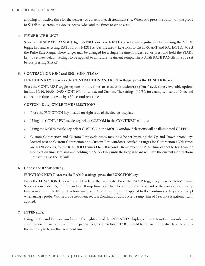
hIgh VolT InsTruCTIons
DYNATRON SOLARIS® PLUS SERIES | SERVICE MANUAL REV. 6 | AUGUST 29, 2017 46
allowing for flexible time for the delivery of current to each treatment site. When you press the button on the probe to STOP the current, the device beeps twice and the timer resets to zero.
4. PULSE RATE RANGE.
Select a PULSE RATE RANGE (High 80-120 Hz or Low 1-10 Hz) or set a single pulse rate by pressing the MODE toggle key and selecting RATES from 1-120 Hz. Use the arrow keys next to RATE-START and RATE-STOP to set the Pulse Rate Range. These ranges may be changed for a single treatment if desired, or press and hold the START key to set new default settings to be applied to all future treatment setups. The PULSE RATE RANGE must be set before pressing START.
5. CONTRACTION (ON) and REST (OFF) TIMES
FUNCTION KEY: To access the CONTRACTION AND REST settings, press the FUNCTION key.
Press the CONT/REST toggle key one or more times to select contraction/rest (Duty) cycle times. Available options include 10/10, 10/30, 10/50, CONT (Continuous). and Custom. The setting of 10/30, for example, means a 10-second contraction time followed by a 30-second rest time.
CUSTOM (Duty) CYCLE TIME SELECTIONS
• Press the FUNCTION key located on right-side of the device faceplate.
• Using the CONT/REST toggle key, select CUSTOM in the CONT/REST window.
• Using the MODE toggle key, select CUST CR in the MODE window. Selections will be illuminated GREEN.
• Custom Contraction and Custom Rest cycle times may now be set by using the Up and Down arrow keys located next to Custom Contraction and Custom Rest windows. Available ranges for Contraction (ON) times are 1-120 seconds, for the REST (OFF) times 1 to 300 seconds. Remember, the REST time cannot be less than the Contraction time. Pressing and holding the START key until the beep is heard will save the current Contraction/Rest settings as the default.
6. Choose the RAMP setting.
FUNCTION KEY: To access the RAMP settings, press the FUNCTION key.
Press the FUNCTION key on the right side of the face plate. Press the RAMP toggle key to select RAMP time. Selections include: 0.5, 1.0, 1.5, and 2.0. Ramp time is applied to both the start and end of the contraction. Ramp time is in addition to the contraction time itself. A ramp setting is not applied to the Continuous duty cycle except when using a probe. With a probe treatment set to a Continuous duty cycle, a ramp time of 3 seconds is automatically applied.
7. INTENSITY.
Using the Up and Down arrow keys to the right-side of the INTENSITY display, set the Intensity. Remember, when you increase intensity, current to the patient begins. Therefore, START should be pressed immediately after setting the intensity to begin the treatment timer.

hIgh VolT InsTruCTIons
DYNATRON SOLARIS® PLUS SERIES | SERVICE MANUAL REV. 6 | AUGUST 29, 2017 47
8. Press START.
Electrodes Pad Treatment: Press START. When you press start, the treatment timer begins counting down.
Probe: Press START on the device followed by ON/OFF on the probe handle to activate a probe treatment. The timer will begin counting up. If you fail to set the intensity on either an electrode or a probe treatment before pressing START, the Intensity display will begin flashing, and you will be unable to start the treatment until the intensity is set.
9. MODIFY Settings
While the High Volt treatment is in progress, TIME, INTENSITY, AND POLARITY can be modified excluding POLARITY for MultiStim probe. Carefully observe the channel indicator lights when modifying a treatment. When a channel’s light is illuminated GREEN, the current treatment parameters for that channel are displayed. Any changes made to the parameters will affect only the channel that is illuminated in GREEN. Use the Channels Toggle key to display the parameters of another channel in order to modify parameters.
10. STOP
When the treatment time has elapsed, the current to the patient stops and a tone sounds signaling the end of a treatment. Treatments in progress may be stopped at any time using one of the following methods.
Stop One Treatment Only. Press and hold the FUNCTION key and press STOP. This stops only the treatment in focus.
Stop All. Press the STOP key. All treatments at all channels will stop.
Stop Time. Reduce the treatment time using the Time arrow key. The output at the selected channel is stopped, and the device then displays the parameters for the next treatment that remains in progress (if there is an active treatment).
Multistim Probe Stop. A probe treatment may be stopped by pressing the ON/OFF key located on the handle of the MultiStim probe.
NOTE: The intensity arrows on the probe handle work the same as the intensity arrows on the device faceplate. Never use High Volt to treat any conditions which contribute to loss of sensation, or an area where the patient cannot feel the electrical stimulation.
NOTE: SAVING DEFAULTS. If the treatment you have just set up is the most common High Volt setup you use, the treatment parameters can be saved as the defaults for your own device. After setting up the treatment, press and hold the START key for two seconds. At the end of two seconds, a beep will sound indicating the treatment parameters have been saved. The next time this modality is chosen, the parameters will be selected automatically.
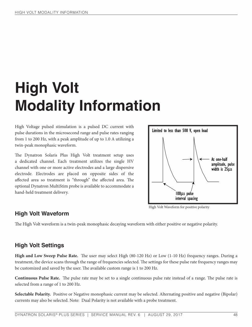
hIgh VolT ModalITy InforMaTIon
DYNATRON SOLARIS® PLUS SERIES | SERVICE MANUAL REV. 6 | AUGUST 29, 2017 48
High Volt Modality InformationHigh Voltage pulsed stimulation is a pulsed DC current with pulse durations in the microsecond range and pulse rates ranging from 1 to 200 Hz, with a peak amplitude of up to 1.0 A utilizing a twin-peak monophasic waveform.
The Dynatron Solaris Plus High Volt treatment setup uses a dedicated channel. Each treatment utilizes the single HV channel with one or more active electrodes and a large dispersive electrode. Electrodes are placed on opposite sides of the affected area so treatment is “through” the affected area. The optional Dynatron MultiStim probe is available to accommodate a hand-held treatment delivery.
High Volt WaveformThe High Volt waveform is a twin-peak monophasic decaying waveform with either positive or negative polarity.
High Volt SettingsHigh and Low Sweep Pulse Rate. The user may select High (80-120 Hz) or Low (1-10 Hz) frequency ranges. During a treatment, the device scans through the range of frequencies selected. The settings for these pulse rate frequency ranges may be customized and saved by the user. The available custom range is 1 to 200 Hz.
Continuous Pulse Rate. The pulse rate may be set to a single continuous pulse rate instead of a range. The pulse rate is selected from a range of 1 to 200 Hz.
Selectable Polarity. Positive or Negative monophasic current may be selected. Alternating positive and negative (Bipolar) currents may also be selected. Note: Dual Polarity is not available with a probe treatment.
High Volt Waveform for positive polarity
hIgh VolT ModalITy InforMaTIon
DYNATRON SOLARIS® PLUS SERIES | SERVICE MANUAL REV. 6 | AUGUST 29, 2017 49
Custom Contraction/Rest Time Cycles. The Dynatron Solaris Plus allows for the choice of muscle contraction and relaxation time cycles (Duty Cycles) from options of 10/10 (ten seconds on and ten seconds off), 10/30, 10/50, Continuous or Custom cycles. The Custom time cycle allows for a Contraction (ON) time from 1 to 120 seconds, and a Rest (OFF) time from 1 to 300 seconds. Remember, the Rest time cannot be less than the Contraction time.
Selectable Ramp Speed. You can choose a ramp speed of .5 (1/2) to 2.0 seconds in half-second increments. For patient comfort, the ramp occurs both before and after the “Contraction” segment of the pulse.
Pulse Duration. The pulse duration is fixed at 25 µs (micro-seconds).
Pulse Pair Interval. The interval between the two pulses in the wave form is fixed at 100 µs.
Intensity Display in Volts. Intensity is displayed in volts (peak voltage with no load) with a range of 1 to 500 volts.
High Volt Default SettingsThe following default settings are set by the manufacturer and are selected when you choose High Volt. You may change these defaults to your own preferred settings. See “Setting Defaults” in this manual.
• High Volt Pads Treatment
• Continuous Duty Cycle
• Treatment Time Electrodes: 10 minutes
• Treatment Time Probe: 0.00
• Polarity: Negative
• Pulse Rate: High Range
Default High Range: ...........................................................................80-120 Hz
Default Low Range: ..................................................................................1-10 H
Available Range:....................................................................................1-200 Hz
High Volt Waveform Specifications
Waveform: ...................................................................Twin peak, monophasic
Pulse Duration: ............................................................................................25 µs
Pulse Rate Range: .............................................................................1 to 200 Hz
Pulse Interval: ............................................................................................100 µs
Maximum Power Output: .................. Limited to less than 500 V, open load

MICroCurrenT InsTruCTIons
DYNATRON SOLARIS® PLUS SERIES | SERVICE MANUAL REV. 6 | AUGUST 29, 2017 50
Microcurrent InstructionsMicrocurrent treatments may be delivered using either electrodes or the optional MultiStim probe. The MultiStim probe option is not available on the 707. For treatment with electrodes, plug one lead into the CHANNEL 1 JACK, and place the two electrodes on the patient before setting up the treatment. For treatment with probes, plug the Dynatron MultiStim Probe into the Stim Probe Jack located on the right-side of the device.
During the Microcurrent treatment the current is delivered to both CHANNEL 1 and to the MULTISTIM PROBE output simultaneously. Therefore, CHANNEL 1 is unavailable for any other treatment while any Microcurrent treatment is in progress (including a single Microcurrent probe treatment).
How To Use The Optional MultiStim Probe For Microcurrent TreatmentsTo set up a Microcurrent Probe treatment, use the end of a cotton swab (such as a Q-Tip®) inserted into the end of both the MultiStim probe (active) and Microcurrent Ground probe. Cut the end of the swab to a short length. The cotton must touch the metal ring at the tip of the probe. Use a conductive electrolyte spray or water to wet the cotton swab before treating. If the cotton dries out during treatment, conductance may become erratic. Re-wet the cotton, if needed.
NOTE: Microcurrent is unavailable if Direct Current is operational.
NOTE: When applying a Microcurrent probe treatment, it is necessary to use either a ground probe or a ground electrode in conjunction with the active MultiStim probe. Attach the banana plug ground wire from the MultiStim probe by plugging it into the back of the ground probe. To use a ground electrode you must use a banana-to-pin adapter to connect the ground wire to the electrode.
MICroCurrenT InsTruCTIons
DYNATRON SOLARIS® PLUS SERIES | SERVICE MANUAL REV. 6 | AUGUST 29, 2017 51
Active Probe: To deliver the current to the patient through the active MultiStim probe, first set up the probe treatment and press Start. Hold the probe as you would hold a pencil and press the ON/OFF button on the probe to start delivery of the current. The active probe should touch the patient’s skin at the treatment site and the ground probe should touch the patient’s skin elsewhere near the treatment site. This completes the circuit and delivers current to the patient. Do not hold the ON/OFF button down. Once the button has been pressed and released, the current is delivered until the button is pressed and released again to stop the current. The unit beeps once when the button is pressed to start the current, and beeps twice when you press the button to stop the current.
During a treatment, observe conductance by listening to the audio tone. Also, the CONDUCTANCE BAR GRAPH will indicate the conductance between patient skin and probe tip, allowing for an optimum treatment.
While delivering current, the treatment timer counts up in seconds from zero. When the current is stopped, the timer returns to zero. Press the ON/OFF button again to commence the next treatment cycle. Continue in this way until treatment is completed.
Ground Probe: The optional ground probe is used to complete the circuit, allowing current to flow through patient’s tissue. The ground probe should touch the patient’s skin at any location away from the treatment point.
Ground Electrode: As an alternative, a dispersive electrode may be used. A hand-held ground probe is not needed when using a ground electrode. This is particularly convenient when treating in several different places around one point.
Unplug the ground probe from its cable, attach a banana to pin adapter to the cable, then attach an electrode to the pin. Place the electrode on the patient at a site where it will not interfere with placement of the active probe during treatment.
Test Mode: Press and release the MultiStim Probe ON/OFF button again to stop delivery of the current. The unit beeps twice to let you know current delivery has stopped. The probe is now in “TEST” mode allowing you to continue monitoring conductance at any point desired. When the probe touches the patient’s skin, conductance continues to be measured and the audio tone is produced. Press and release the button when you wish to return to the Treatment mode.
NOTE: In “TEST” mode during a Microcurrent treatment, a small amount of current is delivered to allow an impedance reading to be taken in order to show conductance. The current delivered during “TEST” mode is either 25 micro amperes or the micro amperage setting for the treatment itself, whichever is less. For purposes of this measurement, current is delivered in pulses of approximately 20 mSec.

MICroCurrenT InsTruCTIons
DYNATRON SOLARIS® PLUS SERIES | SERVICE MANUAL REV. 6 | AUGUST 29, 2017 52
Detailed Microcurrent SetupBefore setting up a Microcurrent treatment with electrodes, attach a lead wire with two electrodes to CH 1. For a probe treatment, connect the optional MULTISTIM PROBE to the STIM OUTPUT jack on the right-side of the device. When a MULTISTIM PROBE treatment is in progress, Channel 1 is not available for any other treatment.
1. Press the MICRO (Microcurrent) Key.
After pressing the MICRO key, the default settings for an electrodes pads treatment are automatically selected.
Microcurrent Quick Setup
1. Press the MICRO key. Channel 1 for electrodes is automatically selected.
2. PROBE TREATMENT. Insert the optional MultiStim probe into the STIM OUTPUT jack. Use the DELIVERY toggle key to select PROBE. Selections are illuminated GREEN.
3. Choose POLARITY (Positive, or Negative. Bipolar selection available only for electrode treatments).
4. Choose POLARITY (Positive, Negative, or Bipolar). Note: Bipolar is not available in when inProbe mode.
5. CONDUCTANCE BAR: PAD: The CONDUCTANCE BAR may be turned ON or OFF by using the COND toggle key. PROBE: Turning the Audible Tone OFF in Probe mode will turn off the Conductance Bar.
6. FREQUENCY. Using the MODE toggle key select FREQ. Use the right-side UP/DOWN arrow keys to change FREQUENCY if desired.
7. INTENSITY. Using the INTENSITY arrow keys or the (+) & (-) switch in the probe handle, change the INTENSITY, if desired.
8. TIME. For electrode treatments only, change the TIME by using the TIME ARROW keys.
9. VOLUME. The Audible Tone volume can be adjusted from 0 (off) to 10 for a Probe Treatment after selecting VOLUME in the MODE window.
10. Press START.
11. STOP. Press and hold the FUNCTION and press the STOP key to stop only the focus treatment appearing in the Treatment Screen. Pressing STOP alone, stops all treatments operating on the device. Using the TIME arrow keys to bring treatment time to zero will also stop a treatment.

MICroCurrenT InsTruCTIons
DYNATRON SOLARIS® PLUS SERIES | SERVICE MANUAL REV. 6 | AUGUST 29, 2017 53
Electrode Pads Default Setting: Time.................................................20 min.
Intensity .............................................50 µA
Frequency .........................................0.3 Hz
Conductance ......................................... On
Delivery ..............................................PADS
Polarity ............................................ Bipolar
For a Probe treatment, insert the MultiStim probe into the STIM PROBE output jack located on the right side to the device. Use the DELIVERY toggle key to select PROBE on the Treatment Display Screen. The Probe defaults will be selected. Note: The bipolar option is not available for a Microcurrent Probe treatment.
Probe Default Setting: Time.........................Counts up from 0.00 (after pressing Probe’s On/Off button)
Intensity .......................................... 300 µA
Frequency ...........................................4 Hz
Audible Tone ....................................... On
Conductance ....................................... On
Delivery .........................................PROBE
Polarity .............Negative Unipolar Wave
If using the treatment default settings, press START. If you wish to use other settings, complete the following steps.
2. Choose ELECTRODE OR PROBE TREATMENT
Choose the output desired. Select CHANNEL 1 for electrodes treatment. For a probe treatment, insert the MultiStim Probe into the STIM PROBE output jack. Press the DELIVERY Toggle key to select PROBE.
3. POLARITY
Using the POLARITY toggle key, select Positive, Negative. Bipolar selection only available for electrode (pads) treatment.
4. TIME
For electrode treatments only, change the TIME, if desired. To change the treatment time, use the Up/Down arrow keys located next to the TIME display. For probes treatment, the TIME display shows zero until treatment begins. After pressing the START key on the faceplate of the device, press the 1/0 (On/Off) button on the probe which will initiate the flow of current. The device beeps once and the timer then counts up from zero (in seconds). When the “1/0” key is pressed again, the current stops, the device beeps twice, and the timer resets to zero.

MICroCurrenT InsTruCTIons
DYNATRON SOLARIS® PLUS SERIES | SERVICE MANUAL REV. 6 | AUGUST 29, 2017 54
5. FREQUENCY
Press the MODE toggle key to select FREQ (Frequency). Using the Up/Down arrow keys located next to the Frequency display, enter the desired frequency (0.1 - 200).
6. INTENSITY
INTENSITY is displayed in microamps (µA). Use the Up/Down arrow keys located next to the Intensity display to set the intensity (10-990 µA).
7. CONDUCTANCE / AUDIBLE TONE
Both the Conductance Bar and the Audible Tone can be turned on and off by using the toggle key beneath their respective display windows. Note: Turning the Audible Tone OFF in Probe mode will turn off the Conductance Bar. When the Probe is PAUSED, sound and conductance are ON.
8. Press START
Electrode Treatments. Pressing START causes the treatment timer to begin counting down and Stim is delivered through Channel 1.
Probe Treatments. Begin by pressing START on the device faceplate, then press and release the 1/0 (On/Off) button on the probe to activate current through the probe. The device beeps once to signal that current delivery has started (it is not necessary to hold the button down while treating). The treatment timer begins counting up in seconds from zero to provide a convenient means of timing the delivery of current at a given point. Press and release the 1/0 button again to stop the current through the probe. The treatment timer returns to zero and the device beeps twice to signal that current delivery has stopped. Continue the treatment cycle in similar fashion for each treatment site. When applying a Microcurrent Probe treatment, it is necessary to use a ground probe or ground electrode in conjunction with the treatment.
9. STOP
When the treatment time has elapsed, the current to the patient stops and a tone sounds signaling the end of a treatment. Treatments in progress may be stopped at any time using one of the following methods.
Stop One Treatment Only. Press and hold the FUNCTION key and press STOP. This stops only the treatment in focus.
Stop All. Press the STOP key. All treatments at all channels will stop.
Stop Time. Reduce the treatment time using the Time arrow key. The output at the selected channel is stopped, and the device then displays the parameters for the next treatment that remains in progress (if there is an active treatment).
NOTE: While the treatment is in progress, treatment parameters can be modified. Separate default parameters may be saved for both electrodes and probe treatments.

MICroCurrenT ModalITy InforMaTIon
DYNATRON SOLARIS® PLUS SERIES | SERVICE MANUAL REV. 6 | AUGUST 29, 2017 55
Microcurrent Modality InformationMicrocurrent is low-volt pulsed microamp stimulation which has been used for symptomatic relief of chronic intractable and post-surgical pain. With the Dynatron Solaris Plus both attended or unattended Microcurrent therapy can be applied. Unattended therapy is delivered using electrodes. Attended therapy is delivered using the optional Dynatron hand-held MultiStim probe.
Due to the very low frequencies generally associated with a Microcurrent treatment, the current is commonly not felt by the patient. However, Microcurrent at high intensity settings or during a probe treatment can sometimes be felt by the patient and may even be uncomfortable. During a probe treatment, this may be the result of current being concentrated at a very small area.
As with all forms of electrotherapy, current density is dependent upon the current setting, the intensity setting, size, and type of electrodes used, and conductance. Higher current density increases the possibility for patient discomfort. The current density can be reduced by decreasing the amount of current (intensity) or increasing the area through which the current is being delivered. The area can be increased by using larger electrodes and/or making sure that the total area of the electrode is actually delivering current.
Microcurrent WaveformsThree different output waveforms (polarities) may be selected with the Dynatron Solaris Plus. Positive and Negative selections are available for both probe and electrodes. An additional bipolar option is available when using electrodes. With Conductance Bar turned off, the first two are unipolar square waves having a monophasic pulse at a 50 percent duty cycle (equal on and off times). In the illustration, the first unipolar waveform has negative polarity only, and the second has positive polarity only. The third waveform is a bipolar (negative and positive) square wave with a 50 percent duty cycle. Microcurrent Waveform
Negative Unipolar Square Wave
Positive Unipolar Square Wave
For bipolar square wave, press the toggle key until both negative and positive waveforms are selected

MICroCurrenT ModalITy InforMaTIon
DYNATRON SOLARIS® PLUS SERIES | SERVICE MANUAL REV. 6 | AUGUST 29, 2017 56
Microcurrent GuidelinesWhen delivering Microcurrent therapy, observe the following guidelines:
1. Use only moderate current. Consult published literature for recommended settings for Microcurrent treatment.
2. When using Microcurrent probes, keep in mind that all of the current is delivered through the tip of the probe resulting in much higher current density than when using electrodes. Therefore, low to moderate intensity settings will be much more comfortable for the patient, especially when treating sensitive areas.
3. When using electrodes, ensure that the area on the patient’s skin where the electrode is to be placed is clean and free of all foreign matter. This includes powders, perfumes, as well as body oils, dirt, and grime. Cleaning with an alcohol wipe should be adequate. Allow the alcohol to fully evaporate before applying the electrodes. Iontophoresis occurs with all electrical current therapies, and can drive any above-surface contaminants below the epidural layer where an allergic reaction may occur.
4. Make sure the electrodes being used are in good condition. The poly adhesive electrodes should have good adhesion over the entire surface area of the electrode. The area where the leads attach to the electrode (either the pin connector or a snap) should not be damaged such that the connection to the backing behind the adhesive is broken. Carbon electrodes should be deep black, and should be free of cracks in the electrode surface.
5. Some patients tend to be much more sensitive to Microcurrent treatments. On patients with this tendency, treat with reduced intensity and/or shorter treatment times with possibly more frequent treatments, if required.
6. If electrodes are placed on an uneven skin surface, such as over a raised mole, the electrode may not adhere evenly over its entire surface and current could be intensified at the raised area, causing discomfort to the patient.
Microcurrent Default SettingsThe following default settings are set by the manufacturer and are selected when a Microcurrent treatment is selected. Default Settings may be changed to your own preferred settings. See “Setting Defaults” in this manual.
Electrodes. The Microcurrent treatment setup with electrodes is the default, and the following parameters are also selected:
Polarity .......................................................... Bipolar
Frequency ........................................................0.3 Hz
Intensity ............................................................50 µA
Time ...............................20 min.- Counts Down
Conductance ........................................................ On

MICroCurrenT ModalITy InforMaTIon
DYNATRON SOLARIS® PLUS SERIES | SERVICE MANUAL REV. 6 | AUGUST 29, 2017 57
Probe. If Probe treatment is selected, the following defaults are automatically selected. Note: Bipolar is not available in Probe mode.
Polarity ...................................................................................Negative Unipolar
Frequency ..................................................................................................... 4 Hz
Intensity ..................................................................................................... 300µA
Time ................................................Determined by Practitioner - Counts Up
Audible Tone ...................................................................................................On
Conductance ...................................................................................................On
Available Ranges.
Frequency ........................................................................................ Between 0.1 and 200 Hz (positve or negative) Biploar 0.0-5.0 Hz
Maximum Voltage: ....................................................................................................................... 60 V (open circuit)
Intensity: ..........................Between 10 and 990 microamps open load, constant current, increments of 10 µA.
Maximum Load Resistance ........................................................................................................................ 500 Ohms
The ranges of .1 to 200 Hz frequency and between 10 and 990 micro amperes intensity are available for setting up both electrodes and probes treatments. For guidance in selecting the appropriate frequency and intensity for a given probes or electrodes treatment, consult published medical literature.

dIreCT CurrenT InsTruCTIons
DYNATRON SOLARIS® PLUS SERIES | SERVICE MANUAL REV. 6 | AUGUST 29, 2017 58
Direct Current InstructionsDirect Current flows in one direction. From a practical perspective, Direct Current can be defined as having a pulse duration long enough to depolarize skeletal muscle when the nerve is not intact. On the Solaris Plus line of devices, Direct Current is a square wave interrupted with a set interpulse duration of 500 mSec. The interrupted treatment is delivered in a continuous train of 0.1 mSec to 500 mSec pulses set at a maximum of 20 mA. Duration, Intensity, and Polarity settings may be adjusted separately, if desired. The Polarity may be set at Positive or Negative. Treatment is provided only through the optional MultiStim probe. The use of various attachments and a dispersive electrode are necessary. The MultiStim probe utilizes the Stim Probe output jack located on the right-side of the Solaris Plus device. ON/OFF controls and INTENSITY keys (+/-) for the MultiStim probe are located on the handle. Direct Current is not available on the 707.
Direct Current Quick SetupChoose DIRECT CURRENT.
1. Plug the MULTISTIM PROBE into the STIM PROBE output jack. Use the DELIVERY toggle key to select PROBE. Attach the dispersive electrode.
2. Choose POLARITY. Negative or Positive. Note: Polarity defaults to Negative.
3. DURATION of each DC pulse. Press the MODE toggle key to select Duration. Set duration using the Up/Down arrow keys next to the Duration display.
4. Place probe tip in contact with patient’s skin.
5. Press the START key followed by the ON/OFF key located on the MultiStim probe.
6. RAMP UP INTENSITY by using the POWER INTENSITY KEYS (+) and (-) located on the handle of the probe. Caution: Probe must be in contact with patient’s skin prior to starting treatment.
7. Treatment will continue until the OFF key on the MultiStim probe is pressed.

dIreCT CurrenT InsTruCTIons
DYNATRON SOLARIS® PLUS SERIES | SERVICE MANUAL REV. 6 | AUGUST 29, 2017 59
Detailed Direct Current Setup
1. Press the DIRECT CURRENT key.
When DIRECT CURRENT is selected, the STIM PROBE output jack automatically becomes active.
2. Plug the MultiStim probe into the STIM PROBE output jack. Use the DELIVERY toggle key to select PROBE. Attach the dispersive electrode.
The default settings for the modality are programmed at 100 mSec, and Negative polarity. If you wish to use the default settings, attach dispersive electrode and place probe in contact with the patient’s skin. Press START on the device followed by the ON/OFF key on the MultiStim probe handle. There is no need to hold down the key. Current delivery begins immediately. Press the POWER INTENSITY (+) (-) KEYS located on the Probe handle until the desired muscle contraction is obtained.
If you wish to change the treatment settings, complete the following steps.
3. Choose POLARITY
Press the POLARITY toggle key and selecting Positive or Negative. The selection will be illuminated GREEN. The default setting is Negative (-). NOTE: Polarity may be changed during setup or during a treatment. Place the probe in contact with the patient’s skin before pressing START.
4. Set PULSE DURATION
Press the MODE toggle key to select Duration. Once Duration has been selected, the DURATION DISPLAY will be visible in the right-hand corner of the Treatment Display Screen. Set duration between 0.1 mSec and 500 mSec per pulse by using the Up/Down arrow keys next to the DURATION DISPLAY. Pulse Duration selections available are 0.1, 0.3, 0.5, 1.0, 10, 100, and 500, with an interpulse duration of 500 mSec. The selected pulse duration will be delivered in a continuous train of pulses set up to a maximum of 20 mA.
5. START.
Press the START key located on the faceplate of the device followed by pressing and releasing the ON key located on the MultiStim Probe handle. When the ON key is pressed, a single beep will be heard, followed by one beep every second as long as the DC current continues to flow.
6. INTENSITY
After the ON key has been pressed, begin ramping up the intensity by pressing the POWER/INTENSITY Up arrow key on the faceplate or by pressing the (+) (-) keys on the handle of the MultiStim probe. The INTENSITY may be set from 1 to 20 mA.
Before selecting the intensity setting for an individual patient, see “Electrotherapy Usage Cautions” in this manual for recommended intensity settings. Also see the section of this manual entitled “Contraindications, Warnings, and Precautions” for specific precautions when treating any conditions contributing to loss of sensation, or anytime the patient cannot feel the electrical stimulation.

dIreCT CurrenT InsTruCTIons
DYNATRON SOLARIS® PLUS SERIES | SERVICE MANUAL REV. 6 | AUGUST 29, 2017 60
7. STOP
When the desired muscle contraction has been reached, press the ON/OFF key on the MultiStim Probe handle to end the treatment. When the ON/OFF key on the probe handle is pressed, two quick beeps will be heard indicating that the DC treatment is complete.
If the DC treatment is in focus, pressing and holding the FUNCTION and pressing the STOP key will also STOP the treatment.
NOTE: Treatment setup may be saved as new Default settings by pressing and holding down the START key until a beep sounds. However, the intensity setting is not saved but must be reset with each individual patient.
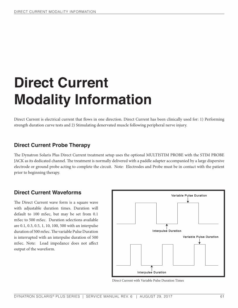
dIreCT CurrenT ModalITy InforMaTIon
DYNATRON SOLARIS® PLUS SERIES | SERVICE MANUAL REV. 6 | AUGUST 29, 2017 61
Direct Current Modality InformationDirect Current is electrical current that flows in one direction. Direct Current has been clinically used for: 1) Performing strength duration curve tests and 2) Stimulating denervated muscle following peripheral nerve injury.
Direct Current Probe TherapyThe Dynatron Solaris Plus Direct Current treatment setup uses the optional MULTISTIM PROBE with the STIM PROBE JACK as its dedicated channel. The treatment is normally delivered with a paddle adapter accompanied by a large dispersive electrode or ground probe acting to complete the circuit. Note: Electrodes and Probe must be in contact with the patient prior to beginning therapy.
Direct Current WaveformsThe Direct Current wave form is a square wave with adjustable duration times. Duration will default to 100 mSec, but may be set from 0.1 mSec to 500 mSec. Duration selections available are 0.1, 0.3, 0.5, 1, 10, 100, 500 with an interpulse duration of 500 mSec. The variable Pulse Duration is interrupted with an interpulse duration of 500 mSec. Note: Load impedance does not affect output of the waveform.
Direct Current with Variable Pulse Duration Times

dIreCT CurrenT ModalITy InforMaTIon
DYNATRON SOLARIS® PLUS SERIES | SERVICE MANUAL REV. 6 | AUGUST 29, 2017 62
Direct Current WarningsIt is important that excellent coupling be maintained any time current is flowing. Increased resistance from poor coupling or excessive current density can cause skin reactions.
• Electrodes must be attached and probe placed in contact with the patient’s skin prior to starting the treatment.
• Direct Current tends to lower surface sensory perception as the treatment proceeds. The patient must have good sensory perception if Direct Current is to be used.
Direct Current Default Setting
Pulse Duration: ...................................................................................100 mSec
Polarity: ..................................................................................................Negative
Intensity: .............................................................................................................1
The following default settings are set by the manufacturer:
Waveform: .................................................................................................Square
Pulse Duration: .............................................................................. .1-500 mSec
Pulse Duration Selections: .................................. 0.1, 0.3, 0.5, 1, 10, 100, 500
Power Output: ........................................................................................20 mA.
Note: Load impedance does not affect output of the DC waveform.

dynaTron TrI-WaVe™ oPeraTIng InsTruCTIons
DYNATRON SOLARIS® PLUS SERIES | SERVICE MANUAL REV. 6 | AUGUST 29, 2017 63
Dynatron Tri-Wave™ Operating InstructionsTri-Wave Light Therapy provides delivery of a single wavelength of light or any combination of 3-wavelengths of light (red, infrared, and blue) that allow for 7 different light treatment combinations. The Tri-Wave Light Probe or 2 robust 5” x 7” Tri-Wave Light Pads deliver the desired treatment. Dual Light Pads allow for greater coverage of a joint, treatment of 2 separate areas at the same time, and the ability to treat large areas of the body when placed side-by-side. The Solaris Plus 707 has the unique ability to utilize two Light Probes and two Light Pads simultaneously.
The Solaris Plus Tri-Wave Light Therapy probe is specifically designed for treating smaller areas. The probe has a treatment area of 6 cm2 and should be applied in direct contact with the surface of the skin over the treatment area. To treat areas larger than 6 cm2 individual treatments should be given one at a time in a grid pattern until the desired treatment area is covered unless treating large areas where the Dynatron Tri-Wave Light Pads (5” X 7” each) would be more suitable. Please see published literature for specific treatment parameters.
The Dynatron Tri-Wave probe and the Dynatron Tri-Wave Pads have been cleared by the FDA to provide topical heating for temporary increase in blood circulation, temporary relief of minor muscle and joint aches, pain and stiffness and relaxation of muscles; for muscle spasms and minor pain and stiffness associated with arthritis.
WARNINGProtective eyewear is required for patient and practitioner.
CAUTIONThe Dynatron Tri-Wave probe and the Dynatron Tri-Wave Pads must be plugged securely into the respective output jacks prior to turning ON the Solaris Plus base console.

dynaTron TrI-WaVe™ oPeraTIng InsTruCTIons
DYNATRON SOLARIS® PLUS SERIES | SERVICE MANUAL REV. 6 | AUGUST 29, 2017 64
Dynatron Tri-Wave™ Light Quick Treatment Setup
1. Remove all gels and lotions from skin surface.
2. While the Dynatron Solaris Plus controlling console is turned OFF, plug the Dynatron Tri-Wave Light probe and/or Dynatron Tri-Wave Light pads into the corresponding output jacks located on the side(s) of the console.
3. Placing protective eyewear on both the patient and the practitioner is required.
4. Turn ON the Dynatron Solaris Plus controlling console.
5. LT PROBE and LT PADS. Press Probe or Light Pad on the Solaris Plus console. When using the 707, press the toggle key below the channels window to select the desired Probe or Pads to activate.
6. Select WAVELENGTHS. Using the Wavelength toggle keys, select the desired wavelengths(Infrared, Blue, Red) by toggling the wavelength ON or OFF. The selection will be illuminated in GREEN when the wavelength is active. Note: Wavelengths cannot be changed during a treatment.
7. TIME/DOSAGE. Using the Up/Down arrow keys located next to the TIME and DOSAGE displays, Dosage/Time may be adjusted. Dosage and Time are calculated according to the wavelengths selected. If changes are made to Dosage, Time, will automatically be recalculated. If changes are made to Time, Dosage will automatically be recalculated.
8. START. Press START on the Dynatron Solaris Plus control console.
Probe. After pressing START on the console, press the 1/0 (ON/OFF) key located on the Probe handle to begin treatment.
Pads. The Pads treatment begins immediately when the console START key is pressed.
9. PAUSE.
Probe. Press the 1/0 (ON/OFF) key located on the Probe handle to pause a Probe treatment or press the PAUSE key located on the console. To continue the treatment, press the 1/0 (ON/OFF) key on the Probe handle or the PAUSE key on the console again.
Pads. With the desired set of Pads as the focus treatment, press the PAUSE key located on the Solaris Plus console. To continue the treatment, press the PAUSE key again.
10. STOP
Probe. Press the 1/0 (ON/OFF) key on the Probe to pause or stop a probe treatment or press the FUNCTION/STOP keys on the console simultaneously.
Pads. Press the FUNCTION/STOP keys on the console to immediately STOP a Pads treatment, reduce the treatment time to zero or allow the treatment to automatically time out.
NOTE: Pressing only the STOP key on the Dynatron Solaris Plus console will terminate all treatments in progress.

dynaTron TrI-WaVe™ oPeraTIng InsTruCTIons
DYNATRON SOLARIS® PLUS SERIES | SERVICE MANUAL REV. 6 | AUGUST 29, 2017 65
Detailed Treatment Setup
1. CLEANSE THE TREATMENT AREA
To insure that all gels and lotions have been removed from the surface of the skin, cleanse the treatment area thoroughly.
2. WHILE THE DYNATRON SOLARIS PLUS CONTROLLING CONSOLE IS TURNED OFF, insert the Dynatron Tri-Wave Light Probe and/or Dynatron Tri-Wave Light Pads into their proper output jacks. The Solaris Plus Light Therapy output jacks are located on the left-side of the console. Light Therapy output jacks on the 707 are located on both sides of the console. Carefully align the connector “keys” to avoid damage to the pins when inserting the probe and pad cable(s) into the jack(s).
3. Place PROTECTIVE EYEWEAR on both the patient and the practitioner.
POWER-ON THE CONSOLE.
After the Pads and/or Probe are plugged into the proper output jack(s), select the “1” (ON) position on the power switch located on the back of the Dynatron Solaris Plus console. If a probe or pads have not been properly attached, an error message will be displayed on the Treatment Display Screen or the probe/pads will not be recognized by the console. It is recommended, if the probe/pads are used frequently, that the unit remain ON with the Dynatron Tri-Wave devices plugged into the console throughout the day.
4. Select PROBE or LIGHT PAD on the Dynatron Solaris Plus console.
Probe. Pressing “PROBE” causes the LT PROBE in the Channels window of the display to be illuminated in GREEN text indicating that the Probe is activated in preparation for treatment.
Probe. Solaris Plus 707. Two LIGHT PROBES may be used at the same time on the 707. Pressing the “PROBE” key will automatically default to the Light Probe located on the left side of the console and LT PB1 will be highlighted in green in the Channels Window. Press the toggle key below the Channels Window to change the focus to the Probe located on the right side. LT PB2 will be activated and highlighted in green.
Pads. Pressing “LIGHT PAD” causes LT PAD in the Channels window of the display to be highlighted in GREEN text indicating that the Pads are activated.
Pads. Solaris Plus 707. Two LIGHT PADS may be operated at the same time on the 707. Pressing the “LIGHT PAD” key will automatically default to the Light Pads located on the left side of the console and LT PD1 will be highlighted in green in the Channels Window. Press the toggle key below the Channels Window to change the focus to the Pads located on the right side. LT PD2 will be activated and highlighted in green.
707 Note. Both Probe and Pad treatments may be operated simultaneously. Press the Toggle Key below the Channels window to bring the desired treatment parameters into focus on the Treatment Display Screen. To set up a new
CAUTIONDO NOT use gels or lotions in combination with Light Therapy. Gels or lotions can clog the vents causing overheating and damage to the internal components. Damage caused by the use of gels and lotions may void your warranty.

dynaTron TrI-WaVe™ oPeraTIng InsTruCTIons
DYNATRON SOLARIS® PLUS SERIES | SERVICE MANUAL REV. 6 | AUGUST 29, 2017 66
treatment, press the TREATMENT MODALITY key for the desired treatment. When a treatment is in focus, the selected treatment will be highlighted in GREEN text within the Channels window and the treatment name will appear in the center of the Treatment Display Screen.
5. Select WAVELENGTHS (Total Energy Delivered)
The user has the capability of selecting a specific wavelength or blending various wavelengths into a single treatment. Wavelengths are selected by using the WAVELENGTH TOGGLE keys to turn the Wavelengths “ON” and/or “OFF.” The default wavelength for the Probe and Pads is Infrared (850nm) and Red (624nm).
To select a wavelength other than the Infrared (850nm) default, press the key under the light therapy option you wish to activate: Red (624nm), Blue (464nm), or Infrared (850nm). Pressing the key under each option will cause the ON text to become illuminated. Pressing the key again will cause the OFF text to illuminate. Selections may be activated individually or in any combination.
Dosage (J/cm2 ) is calculated as a combination of Time and Power, and is automatically calculated once the Wavelength selections have been made. Dosage can manually be altered by using the Up/Down arrow keys located on the right-side of the Dosage display. When Dosage is altered, treatment time is automatically adjusted.
Dynatron Tri-Wave™ Light Wavelength SettingsThe following tables list wavelength selections or combination of selections with their respective dosage and treatment times.
TRI-WAVE LIGHT PROBE DEFAULTSWaVelengThs defaulT dosage PoWer ouTPuT mW TIMe
Infrared (Ir) – (850nm) 6 j/cm2 1000 mW 35 sec.
blue – (464nm) 6 j/cm2 500 mW 1 min. 12 sec.
red – (624nm) 6 j/cm2 500 mW 1 min. 12 sec.
Infrared and red 6 j/cm2 800 mW 44 sec.
blue and Infrared 6 j/cm2 800 mW 48 sec.
Infrared, blue and red 6 j/cm2 650 mW 1 min.
blue and red 6 j/cm2 525 mW 1 min. 11 sec.
NOTE: Wavelength selections cannot be changed during a treatment.

dynaTron TrI-WaVe™ oPeraTIng InsTruCTIons
DYNATRON SOLARIS® PLUS SERIES | SERVICE MANUAL REV. 6 | AUGUST 29, 2017 67
TRI-WAVE LIGHT PAD DEFAULTSInfrared (Ir) – (850nm) 10 j/cm2 5160 mW 10 min.
blue – (464nm) 10 j/cm2 2090 mW 10 min.
red – (624nm) 10 j/cm2 2580 mW 20 min.
Infrared and red 10 j/cm2 4128 mW 9 min. 50 sec.
blue and Infrared 10 j/cm2 4092 mW 8 min. 23 sec.
Infrared, blue and red 10 j/cm2 3599 mW 8 min. 42 sec.
blue and red 10 j/cm2 2802 mW 13 min. 20 sec.
6. SAVING CUSTOM SETTINGS
Newly programmed custom settings can be saved as default settings for future treatments by pressing and holding down the START key until a tone/beep is heard. If selections are not saved, the modality settings will return to the original default settings once the treatment is complete.
When creating Custom Settings for the Solaris Plus 707, because there are multiple identical accessories (2 Tri-Wave Light Probes, 2 Pads, and 2 ThermoStim Probes), the Custom Default Setting set for one accessory, such as the Tri-Wave Light Probe, becomes the Default Setting for all Tri-Wave Light Probe treatments. The same is true for the Tri-Wave Light Pads as well as the ThermoStim Probes.
7. START
Probe. After pressing START on the console, the yellow LED on the probe handle will be illuminated indicating that there is power to the probe. Press the 1/0 (ON/OFF) toggle key located on the Probe handle to begin treatment. The green LED on the probe handle will be illuminated and the treatment time indicated in the Time display window will begin counting down to zero. While the treatment is in progress and in “focus” LT PROBE (LTPB1 or LTPB2) will be illuminated in GREEN text in the Channels window. When the countdown reaches zero a tone will sound and the green LED on the Probe handle will turn off and the yellow LED will be illuminated. Another cycle of the same duration and dosage may be activated by pressing the 1/0 (ON/OFF) key on the probe handle.
1/0 (On/Off/Pause) Key

dynaTron TrI-WaVe™ oPeraTIng InsTruCTIons
DYNATRON SOLARIS® PLUS SERIES | SERVICE MANUAL REV. 6 | AUGUST 29, 2017 68
Expect to hear the probe fan go on and off during a treatment as the fan is designed to maintain a consistent internal probe temperature. If for any reason the internal temperature of the probe exceeds set limits, the word HOT will appear on the display and the treatment will be automatically paused until the internal probe temperature returns to prescribed limits.
Pads. The Dynatron Tri-Wave light pad treatment will immediately begin when START is pressed on the console. LT PAD (LTPD1 or LTPD2) will be illuminated in green text in the Channels Window when the treatment begins and is the “focus” treatment. The treatment time will be displayed in the Time Display Window and will begin to count down to zero. When the treatment time has counted down to “0,” a tone will sound, alerting the practitioner that the treatment is complete. Another cycle of the same duration and dosage may be activated by pressing the START key agai
8. PAUSE
Probe. Press the 1/0 (ON/OFF) toggle key located on the probe handle to Pause and Restart a treatment at any time. When the treatment is active, the green LED on the handle of the probe will be illuminated. When the treatment has been Paused or is OFF, the yellow LED on the handle will be illuminated.
Pads. With the Dynatron Tri-Wave™ Light Pad as the focus treatment, press the PAUSE key located on the Console. To continue the treatment, press the PAUSE key again.
9. STOPProbe. With the Probe as the “focus” treatment, pressing and holding FUNCTION followed by the STOP key will stop the Probe treatment. Treatment may be paused by pressing the 1/0 (ON/OFF) key located on the probe handle.
Pad. With the Pad as the “focus” treatment, pressing and holding FUNCTION followed by the STOP key will stop the Pad treatment or allow the treatment to time out.
Dynatron Tri-Wave™ Light Treatment Notes
• Always cleanse the probe, pad, and treatment area thoroughly before beginning each treatment to avoid skin irritation or infection.
NOTE: Pressing STOP on the Console will stop ALL TREATMENTS in progress and reset the device to the last saved preset default values.
CAUTIONThe vents on the Probe handle should be clear and free of any obstruction during treatment. Never use gels or lotions with a light probe treatment.

dynaTron TrI-WaVe™ oPeraTIng InsTruCTIons
DYNATRON SOLARIS® PLUS SERIES | SERVICE MANUAL REV. 6 | AUGUST 29, 2017 69
• DO NOT use gels or lotions in combination with Light Therapy. Gels may clog the vents causing overheating and damage to the internal components.
• DO NOT attempt to unscrew or tighten down the probe lens. This is not a threaded part. There are no user serviceable parts in the Tri-Wave Light probe.
• If the treatment area is larger than the size of the Probe aperture, then areas equal in size to the aperture (6 cm2) should be treated one at a time until the entire area is covered.
• Do not “bathe” the area by moving the Probe back and forth or in some other manner over the target area. Failure to make full contact with the treatment surface may result in outcomes that are less effective. Other methods may reduce total energy absorption. If the area is large, then the Tri-Wave Light Pads (two 5” x 7” pads) may be a more appropriate treatment option.
• When treating the patient, the Tri-Wave Light Probe or Pads should be placed on the skin over the treatment area. Maintaining constant contact with the skin is essential during treatment.
• DO NOT use over open wounds unless covered with a clear protective barrier (clear plastic wrap). An open wound may be treated in the non-contact mode without protective barrier however energy delivery will be diminished. Undue pressure should not be exerted on the wound bed.
• Never use water or cleansing agents on the Tri-Wave Light Probe Head or Pads. Caustic cleansers (even liquid cleansers) may cause damage. DO NOT USE ISOPROPYL ALCOHOL. A soft cloth lightly damped with water and a small amount of non-caustic soft soap may be used. Wipe with a damp cloth to rinse. If seeking a commercial cleanser/disinfectant it is recommended that a product contain only the following active ingredients to avoid damage to the probe or pads:
OctylDecyl Dimethyl Ammonium Chloride
Dioctyl Dimenthyl Ammonium Chloride
Didecyl Dimenthyl Ammonium Chloride
Alkyl (C14 50%; C12 40%; C16 10
Dimenthyl Benzyl Ammonium Chloride
Other Ingredients not published.
WARNINGThis therapy must be used cautiously where sensory nerve damage is present or in any case where there is a loss of normal skin sensation; including areas desensitized by medication or other therapies such as any type of cryotherapy.

dynaTron TrI-WaVe™ lIghT ModalITy InforMaTIon
DYNATRON SOLARIS® PLUS SERIES | SERVICE MANUAL REV. 6 | AUGUST 29, 2017 70
Dynatron Tri-Wave™ Light Modality InformationThe Dynatron Tri-Wave™ light probe and Dynatron Tri-Wave™ Light Pad have been cleared by the FDA to provide topical heating for temporary increase in blood circulation, temporary relief of minor muscle and joint aches, pain and stiffness and relaxation of muscles; for muscle spasms and minor pain and stiffness associated with arthritis.
Dynatron Tri-Wave™ Light Basic Vocabulary
Watt (W) ...........................................................................Energy (1 Joule) delivered per second
Milliwatt (mW) One thousandth of a watt. Power and dose determines length of treatment
Nanometer (nm) .................................................................................... One billionth of a meter.
Joule(s) .........................................................................Watts x seconds = total energy delivered
Dose (per cm2) ............ J/cm2 – total energy delivered per square cm in a set period of time.
Dynatron Tri-Wave™ Light Probe And Light Pad SpecificationsFollowing are the General Specifications for the Dynatron Tri-Wave Light Probe and Dynatron Tri-Wave Light Pad. Other ranges, accuracy and precision values that are not provided here may be obtained from Dynatronics upon request.
The Dynatron Tri-Wave Light Probe is designed with super luminous diodes emitting three different wavelengths of light. The 20 Infrared SLEDs have a wavelength of 850nm, the 8 Red SLEDs have a wavelength of 624nm and the 6 Blue SLEDs have a wavelength of 464nm.

dynaTron TrI-WaVe™ lIghT ModalITy InforMaTIon
DYNATRON SOLARIS® PLUS SERIES | SERVICE MANUAL REV. 6 | AUGUST 29, 2017 71
Dynatron Tri-Wave™ Light Probe Specifications
Light Source .......................34 Super Luminous Diodes
Wavelengths .....................20 Infrared Diodes – 850nm
8 Red Diodes – 624nm
6 Blue Diodes – 464nm
Power Output ........................ Max 1000mW (+/- 20%)
Treatment Area........................................................6 cm2
Thermal Threshold ............................ 104°F in 2.7 min.
Dynatron Tri-Wave™ Light PadThe Dynatron Tri-Wave™ light pad consists of two 5” x 7” treatment pads connected with a 24” cable between them and a 72” bifurcated cable connecting the pads to the Dynatron Solaris Plus controlling console. Dual pads allow for greater coverage of a joint, treatment of two separate areas simultaneously, and the ability to treat large areas of the body when placed side-by-side.
Dynatron Tri-Wave™ Light Pad Specifications Light Source .................................................................................. 176 Super Luminous Diodes (per pad)
Wavelengths ........ 112 Infrared Diodes – 850nm; 40 Red Diodes – 624nm; 24 Blue Diodes – 464nm
Power Output ....................................................................................................... Max 5160mW (+/- 20%)
Treatment area .................................................................................................................................... 352cm2
Thermal Threshold ........................................................................................................... 104°F in 3.9 min.
6 Blue Diodes 464nm
8 Red Diodes 624nm
20 Infrared Diodes 850nm
Tri-Wave Light Pad - two 5" x 7" pads

ulTrasound InsTruCTIons
DYNATRON SOLARIS® PLUS SERIES | SERVICE MANUAL REV. 6 | AUGUST 29, 2017 72
Ultrasound InstructionsThe following Ultrasound Instructions are for Solaris Plus 708 and 709 USERS ONLY. The Dynatron Solaris Plus 705, 706, and 707 do not offer the Ultrasound feature.
Ultrasound therapy channels sound waves through muscle, nerve, bone, and connective tissue to aid in reducing pain, muscle spasms, and joint contractures.
The physiological effect of Ultrasound therapy depends upon the frequency of the Ultrasound signal. The lower frequency (1 MHz) penetrates deeper than a higher frequency (such as 2 MHz or 3 MHz), thus the practitioner can decide which frequency to use according to the condition and depth to be treated.
A section in this manual entitled “Ultrasound Usage Cautions” provides some general guidelines for Ultrasound treatment and selection of the appropriate soundhead to help ensure safe and effective treatments are delivered to your patients. Further information about Ultrasound application may be obtained from published medical literature.
WARNING• ALWAYS keep the applicator soundhead in constant motion.
• ALWAYS keep the soundhead properly coupled to the patient’s skin or submerged underwater when intensity is turned on.
• Use ample conductive gel to ensure good coupling throughout the treatment. If needed, apply additional gel during the treatment.
• See the section of this manual entitled “Contraindications, Warnings, and Precautions” for Ultrasound treatments.
• Be alert for any sign of periosteal (bone) pain.
• Be sure to read all instructions for operation before treating a patient.
• Use of controls or adjustments or performance of procedures other than those specified herein may result in hazardous exposure to ultrasonic energy.

ulTrasound InsTruCTIons
DYNATRON SOLARIS® PLUS SERIES | SERVICE MANUAL REV. 6 | AUGUST 29, 2017 73
Make sure a soundhead is firmly plugged into the device before turning the device on. When changing to a different size soundhead, turn the machine off first, remove the soundhead, plug in the desired soundhead, then turn the machine on again. Please acquaint yourself with the following terms and device features prior to delivering an Ultrasound treatment.
Soundhead WarmingSoundhead Warming is an optional feature used to maintain a comfortable soundhead temperature for the patient. When Soundhead Warming is ON, the soundhead should remain in its holder as a small amount of Ultrasound output is emitted from the soundhead (0.1 W/cm2). The soundhead warming mode is automatically stopped during a treatment, and resumes automatically as needed after a treatment has ended.
If Soundhead Warming is ON and SOUND has been selected but is not the focus treatment, the word SOUND in the CHANNELS window will be illuminated ORANGE.
Although the Soundhead Warming feature defaults to OFF, it can be turned ON at any time. To turn ON the feature, select SOUND, followed by FUNCTION key. Using the WARMING toggle key, select ON.
CouplingThe term “coupling” refers to the ability to deliver ultrasonic waves from the soundhead to the skin surface with as little impedance or dissipation of power as possible. Coupling (contact between the soundhead and the treatment site) may be provided by a coupling agent such as a gel or lotion. Any material used as a coupling agent must be highly conductive of ultrasonic waves. Air is a very poor conductor of ultrasonic waves. Holding the soundhead in the air while a treatment is running may also damage the soundhead crystal and/or stress electronic components in the device.
If any part of the soundhead is exposed to air during the treatment, coupling is decreased. The air bubbles in a whirlpool, for example, can decrease the effective Ultrasound therapy to the patient. Avoid allowing any air between the soundhead and the treatment area. Water is an excellent conductor of ultrasonic waves; therefore, underwater treatments provide excellent coupling.
CAUTION• Do not drop the soundhead on the hard surfaces.
• Do not cool the soundhead with ice water or ice packs.
• Do not allow the soundhead to overheat repeatedly.
• Do not hold the soundhead in the air while a treatment is running.
All of these conditions are likely to damage the soundhead crystal and/or to stress electronic components in the device. Damage caused by these conditions is not covered by warranty.

ulTrasound InsTruCTIons
DYNATRON SOLARIS® PLUS SERIES | SERVICE MANUAL REV. 6 | AUGUST 29, 2017 74
During any Ultrasound treatment the soundhead should be moved continuously, covering an area approximately twice the size of the soundhead. The full surface of the soundhead should maintain contact with the patient’s skin (except with underwater treatments).
Head Temperature Hot DisplayIf coupling (the effective degree to which the Ultrasound energy is delivered from the soundhead to the patient’s body) is not adequate during treatment, the temperature of the soundhead rises and the patient does not receive the full intended dosage. The Dynatron Solaris Plus TEMPERATURE bar reflects the amount of soundhead heating caused by poor coupling to ensure that the patient is receiving the optimal treatment and that the soundhead crystal is protected from overheating.
When the coupling is acceptable, the length of the Blue/Green segment lights on the coupling bar will remain less than half the length of the bar or less. If the soundhead approaches a temperature of 103 degrees Fahrenheit, the TEMPERATURE BAR begins to increase in length and the colored bar moves past the center mark and continues to lengthen.
If the SOUNDHEAD reaches approximately 103 degrees, a caution will appear in the Treatment Display Screen: “CAUTION, SOUNDHEAD IS GETTING HOT.” Following the caution, the treatment should be terminated and the soundhead cooled. If the SOUNDHEAD reaches approximately 108 degrees, SOUND will be disabled and the Treatment Display Screen will read: “SOUNDHEAD IS TOO HOT! OUTPUT HAS BEEN DISABLED TO ALLOW COOLING.”
NOTE: If the soundhead becomes too hot the SOUNDHEAD HOT warning will appear in the Treatment Screen whether SOUND is the focus treatment or not.
The soundhead must then be cooled down before the treatment can resume. When the soundhead cools sufficiently, press PAUSE or START to resume the treatment. The output power resumes, the display returns to its normal state, and the timer resumes. The soundhead should cool quickly if placed in the soundhead holder or if held exposed to the air. Larger soundheads take longer to cool than smaller heads. If the soundhead is not cooling as quickly as needed to resume the treatment, it can be placed in room temperature water to quicken the cooling process. Sometimes just applying more conductive gel will adequately cool the head.
NEVER USE ICE OR ICE PACKS TO COOL THE SOUNDHEADS as this is likely to cause thermal shock to the electronic components of the soundhead and may necessitate a costly repair. Heads damaged by thermal shock are not covered by the warranty.
To prevent overheating of the soundhead, maintain good coupling throughout the treatment by applying ample conductive gel or lotion. Reducing the power when treating an area where it is difficult to obtain good coupling will also keep the soundhead from overheating.
Display Watts or W/cm2
Power for the Dynatron Solaris Plus may be displayed as WATTS or W/cm2. To choose the desired option, select SOUND, then press the DISPLAY toggle key under the DISPLAY window and select WATTS or W/cm2. The default setting for power is W/cm2; however, the display you prefer may be selected at any time before or during a treatment. Power selection may be saved by pressing and holding down the START key until a beep sounds.

ulTrasound InsTruCTIons
DYNATRON SOLARIS® PLUS SERIES | SERVICE MANUAL REV. 6 | AUGUST 29, 2017 75
Detailed Ultrasound Setup
1. Press SOUND.
Press SOUND to select an Ultrasound treatment. The Default Parameters automatically appear in the Treatment Display Screen. Following are the Ultrasound Default Parameters:
Frequency ........................................1 MHz
Duty ......................................... Continuous
Display ..............................................W/cm2
Time...................................................5 min.
Press the FUNCTION key to view the following:
Parameter ...................................Frequency
Warming .............................................. OFF
If you wish to use the default settings, increase the Intensity to desired treatment level and press START. If you wish to customize settings, follow steps outlined below.
Ultrasound Quick SetupSelect SOUND.
1. FREQUENCY. Using the FREQUENCY toggle key select 1 MHz, 2 MHz, or 3 MHz.
2. DUTY CYCLE. Using the DUTY toggle key, select 10%, 20%, 50% or CONT (Continuous).
3. TIME. Change the treatment TIME, if desired using the Up/Down arrow keys.
4. INTENSITY. Using the Up/Down arrow keys, raise the INTENSITY to desired level.
5. Press START.
6. STOP. Press and hold the FUNCTION and press the STOP key to stop only the focus treatment appearing in the Treatment Display Screen. Pressing STOP alone, stops all treatments operating on the device. Using the TIME arrow keys to bring treatment time to zero will also stop a treatment.

ulTrasound InsTruCTIons
DYNATRON SOLARIS® PLUS SERIES | SERVICE MANUAL REV. 6 | AUGUST 29, 2017 76
2. Choose the FREQUENCY.
Press the FREQUENCY toggle key located under the FREQUENCY window to select 1, 2, or 3 MHz. Any one of the three Frequencies may be selected with the 2 cm2, 5 cm2 or 10 cm2 soundhead.
3. Select the DUTY CYCLE.
Press the DUTY CYCLE toggle key to select one of the four available options: 10%, 20%, 50%, or Continuous duty cycles.
4. Press the FUNCTION key located on the console to display additional parameters.
5. HEAD WARMING.
Press the FUNCTION key to access the Head Warming option. Using the WARMING Toggle key the Head Warming feature may be turned ON or OFF.
6. TIME.
The default time is set for a 5 minute treatment. Time can be changed by using the TIME Up/Down arrow keys located to the left of the TIME display.
7. Raise the INTENSITY.
Use the INTENSITY Up/Down arrow keys to increase the power to the desired setting. For patient safety and comfort, it is recommended that treatment begins with .1 W/cm2, then increase power to the desired level after the treatment begins. Valid ranges are from 0.1 to 2.0 W/cm2 (exceptions: valid ranges when using a 10 cm2 head at 3 MHz are from 0.1 to 1.0 W/cm2).
8. Press START.
Press START, the treatment timer begins counting down and output is delivered to the soundhead. If you fail to set the Intensity before pressing START, a reminder will appear in the lower-right corner of the Treatment Display Screen: “CANNOT START TREATMENT WITH ZERO INTENSITY.”
9. SAVING DEFAULTS. If the treatment you have just set up is the most common Ultrasound setup you use, new defaults may be saved by pressing and holding down the START key for two seconds. At the end of two seconds, a beep will sound indicating the treatment parameters have been saved. The next time SOUND is selected, these parameters will be selected automatically.
10. MODIFY a treatment in progress, if desired.
While the treatment is in progress, the following parameters can be modified: FREQUENCY, DUTY CYCLE, TIME, INTENSITY, and DISPLAY of Watts or Wcm2.
11. PAUSE. Temporarily PAUSE a treatment, if necessary, while the treatment is in progress.
To temporarily PAUSE an Ultrasound treatment, press the PAUSE key. Two quick tones will sound indicating that the treatment has been paused. The Ultrasound output from the soundhead stops and the treatment timer is paused

ulTrasound InsTruCTIons
DYNATRON SOLARIS® PLUS SERIES | SERVICE MANUAL REV. 6 | AUGUST 29, 2017 77
without ending the treatment. Press the PAUSE key again to restart the treatment. A tone will sound indicating that the treatment is again in progress. Output resumes and the treatment timer starts from where it was paused.
12. STOP.
When the treatment time has elapsed, the ultrasound to the patient stops and a tone sounds signaling the end of a treatment. Treatments in progress may be stopped at any time using one of the following methods.
Stop One Treatment Only. Press and hold the FUNCTION key and press STOP. This stops only the treatment in focus.
Stop All. Press the STOP key. All treatments at all channels will stop.
Stop Time. Reduce the treatment time using the Time arrow key. The output at the selected channel is stopped, and the device then displays the parameters for the next treatment that remains in progress (if there is an active treatment).
NOTE: During a COMBO treatment, THE STIM OUTPUT OF THE TREATMENT IS NOT PAUSED when the PAUSE key is pressed, although the Ultrasound output is stopped and the treatment timer is paused.

ulTrasound ModalITy InforMaTIon
DYNATRON SOLARIS® PLUS SERIES | SERVICE MANUAL REV. 6 | AUGUST 29, 2017 78
Ultrasound Modality InformationFor Dynatron Solaris® Plus 708 and 709 users only. The Dynatron Solaris® Plus 705, 706, and 707 do not offer the Ultrasound feature.
Ultrasound, by its very nature, has the ability to irritate the patient’s skin. While the benefits of Ultrasound far outweigh any disadvantages, certain precautions should be observed to assure maximum safety and comfort for your patients.
A patient’s tendency to have adverse reactions to Ultrasound is dependent upon several factors. Some of these factors are discussed below.
Selecting the Appropriate Soundhead
Head and Crystal Size Comparison
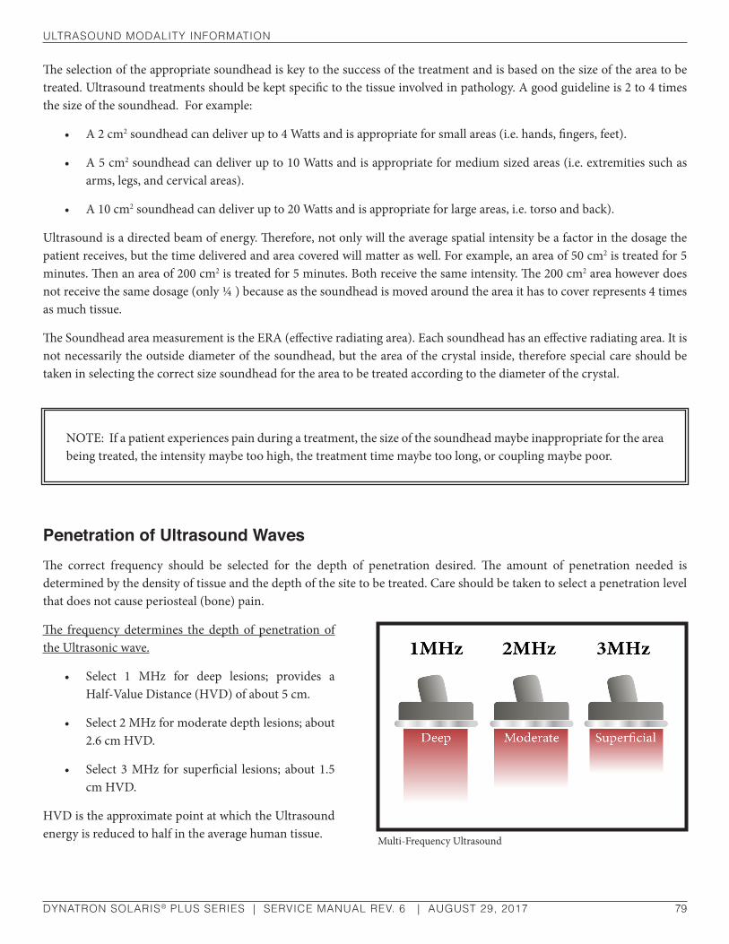
ulTrasound ModalITy InforMaTIon
DYNATRON SOLARIS® PLUS SERIES | SERVICE MANUAL REV. 6 | AUGUST 29, 2017 79
The selection of the appropriate soundhead is key to the success of the treatment and is based on the size of the area to be treated. Ultrasound treatments should be kept specific to the tissue involved in pathology. A good guideline is 2 to 4 times the size of the soundhead. For example:
• A 2 cm2 soundhead can deliver up to 4 Watts and is appropriate for small areas (i.e. hands, fingers, feet).
• A 5 cm2 soundhead can deliver up to 10 Watts and is appropriate for medium sized areas (i.e. extremities such as arms, legs, and cervical areas).
• A 10 cm2 soundhead can deliver up to 20 Watts and is appropriate for large areas, i.e. torso and back).
Ultrasound is a directed beam of energy. Therefore, not only will the average spatial intensity be a factor in the dosage the patient receives, but the time delivered and area covered will matter as well. For example, an area of 50 cm2 is treated for 5 minutes. Then an area of 200 cm2 is treated for 5 minutes. Both receive the same intensity. The 200 cm2 area however does not receive the same dosage (only ¼ ) because as the soundhead is moved around the area it has to cover represents 4 times as much tissue.
The Soundhead area measurement is the ERA (effective radiating area). Each soundhead has an effective radiating area. It is not necessarily the outside diameter of the soundhead, but the area of the crystal inside, therefore special care should be taken in selecting the correct size soundhead for the area to be treated according to the diameter of the crystal.
Penetration of Ultrasound WavesThe correct frequency should be selected for the depth of penetration desired. The amount of penetration needed is determined by the density of tissue and the depth of the site to be treated. Care should be taken to select a penetration level that does not cause periosteal (bone) pain.
The frequency determines the depth of penetration of the Ultrasonic wave.
• Select 1 MHz for deep lesions; provides a Half-Value Distance (HVD) of about 5 cm.
• Select 2 MHz for moderate depth lesions; about 2.6 cm HVD.
• Select 3 MHz for superficial lesions; about 1.5 cm HVD.
HVD is the approximate point at which the Ultrasound energy is reduced to half in the average human tissue.
NOTE: If a patient experiences pain during a treatment, the size of the soundhead maybe inappropriate for the area being treated, the intensity maybe too high, the treatment time maybe too long, or coupling maybe poor.
Multi-Frequency Ultrasound

ulTrasound ModalITy InforMaTIon
DYNATRON SOLARIS® PLUS SERIES | SERVICE MANUAL REV. 6 | AUGUST 29, 2017 80
Types of DeliveryUltrasound can be delivered in four different ways. You will likely only see two of the four methods in clinical practice.
1. Direct Contact Movable. Here the soundhead is placed in direct contact with the patient. A coupling agent is used between soundhead and the patient’s skin. The soundhead is moved slowly, but continuously. This is the method of choice.
The rate of speed at which the applicator moves across the skin is very important in determining how much Ultrasonic output is delivered. If the rate is too slow, the patient may feel periosteal pain (bone ache/pain). If the rate is too fast, or if the applicator head becomes uncoupled with the skin, the amount of treatment is reduced. Uncoupling can also cause the soundhead to overheat.
2. Immersion Method. Here the area to be treated is placed underwater. The soundhead is water tight so it can be immersed with the area to be treated. The water becomes the coupling agent. The head is always moving around the surface area, but not in contact (1/2 to 1 inch away).
3. Hydrogel Disk. For treating crater wounds, cover the wound with a hydrogel disk and apply the soundhead to the disk. This allows direct wound sonation without bringing the soundhead in direct contact with the wound.
4. Stationary Soundhead. This method is dangerous. Hot spots can develop. Do not use.
Treatment Time
For Sub-Acute Conditions: area to be treated (cm2)
= minutes of treatment
1.5 x ERA
For Chronic Conditions: area to be treated (cm2)
= minutes of treatment
1.0 x ERA
For Maximal Thermal Effect: area to be treated (cm2)
= minutes of treatment
.8 x ERA
Treatment IntensitySeveral factors come into play as one decides the level of intensity for the treatment.
1. Superficial lesions require less intensity.
2. Less intensity should be used if bone is superficial to the treatment field.
3. Less intensity should be used when the stage of the injury makes heating questionable.

ulTrasound ModalITy InforMaTIon
DYNATRON SOLARIS® PLUS SERIES | SERVICE MANUAL REV. 6 | AUGUST 29, 2017 81
4. Use a little lower intensity for the first treatment to gauge response.
5. Patient feedback is key. A treatment should feel warm, but the patient should never feel heat, pain, stabbing, pricking or dull ache.
Acute Conditions: ........................................ 0.1 – 0.5 W/cm2 (no appreciable thermal effect).
Sub-Acute Conditions: ...........................0.5 – 1.0 W/cm2 (Mild to Moderate thermal effect).
Chronic Conditions: ............................1.0 – 2.0 W/cm2 (Moderate to Strong thermal effect).
Frequency of TreatmentTreatment can be given daily. It is not uncommon to give Ultrasound twice daily, but this may be excessive. Some guidelines may be helpful.
1. Daily may be the best maximum frequency.
2. Ultrasound can be effectively given every other day.
3. Ultrasound should give some positive benefits by the 3rd or 4th application. If not, discontinue the treatment and consider other options.
4. A maximum of 12 to 15 Ultrasound treatments should be given. If the result desired has not been reached by this point, Ultrasound may not be the proper choice. EXCEPTION: Some Chronic conditions which cause adhesions.
Usage Cautions – Combination TreatmentsWhen using a Stim device in conjunction with a Solaris Plus device to output Stim through the soundhead, observe all con-traindication, warnings, precautions, and usage cautions provided by the manufacturer for all modalities involved.
Potential for Burns or Periosteal PainSome patients’ skin is more sensitive to Ultrasound output. This can cause a reaction similar to a heat rash. It is also possible for a patient to suffer a burn from Ultrasound therapy if the therapy is not administered properly. This can occur for the following reasons:
• Intensity (power) too high
• Frequency too low
NOTE: It is very common that intensity is always 1.5 W/cm2. This is incorrect in many cases. A more specific intensity should be used based on patient response and stage of injury.

ulTrasound ModalITy InforMaTIon
DYNATRON SOLARIS® PLUS SERIES | SERVICE MANUAL REV. 6 | AUGUST 29, 2017 82
• Holding the soundhead in one place on the patient’s skin
• Moving the soundhead too slowly
• Treating an area where sensory nerve damage is present with a loss of normal skin sensation
• Time (Caution: Don’t treat too long).
Bony prominences are especially susceptible, as they reflect sound waves and increase intensity to the periosteum resulting in a burning sensation. Desensitized areas can be overheated or burned without the patient realizing it, so extreme care must be taken with these patients (e.g. diabetes, neural damage, etc.)
Burns can be avoided as long as the treatment causes no pain, tingling, excess heat or aching (for patients with normal skin sensation). Use sufficient coupling agent and make sure there are no bubbles in the gel. When treating in water, clear the bubbles off the soundhead and off the patient’s skin.
An un-calibrated soundhead can also cause tingling, excess heat, aching, or a burning sensation.
Read Ultrasound Contraindication, Warning, & Precaution in this manual for more information.
soundhead oPTIMIzaTIon addIng or rePlaCIng soundheads
DYNATRON SOLARIS® PLUS SERIES | SERVICE MANUAL REV. 6 | AUGUST 29, 2017 83
Soundhead Optimization Adding or Replacing Soundheads
Entering Parameters for Solaris Plus 708 and 709
To ensure soundhead output is optimized, please carefully follow the instructions provided. If you have any questions about the following instructions, contact Dynatronics’ Customer Service Department before proceeding ((800) 874-6251).
1. Head Calibration Printout.
Soundheads are shipped with a Head Calibration Printout sheet. The sheet contains calibration numbers unique to the each specific soundhead. The soundhead serial number appears on the sheet to assist in matching the correct soundhead with the printed parameters. The printout should be kept for future use.
CAUTIONSoundheads CAN successfully be moved between different Solaris devices ONLY if the parameters for that soundhead are entered into the device. Entering parameters ensures the optimization of soundhead output.

soundhead oPTIMIzaTIon addIng or rePlaCIng soundheads
DYNATRON SOLARIS® PLUS SERIES | SERVICE MANUAL REV. 6 | AUGUST 29, 2017 84
Dynatronics Soundhead Sample Parameters Printout
2. Turn the Solaris Plus Device OFF. Plug in the new soundhead. Turn the Solaris Plus ON.
3. Press the SOUND key followed by the FUNCTION KEY.
4. As a default, FREQUENCY should appear in the PARAMETER window and 1 MHz in the FREQUENCY window. Using the Up/Down arrow keys located next to the FREQUENCY display, select the FREQUENCY value for 1 MHz listed on the Parameter’s printout.
NOTE: THE NUMBERS ABOVE ARE PROVIDED FOR ILLUSTRATION ONLY AND SHOULD NOT BE ENTERED INTO YOUR DYNATRON DEVICE. USE ONLY THE ACTUAL NUMBERS PROVIDED WITH YOUR OWN SOUNDHEAD.
Serial: Manufacture Date: 9/15/2012 Size (cm): 5 Cal Date: 9/15/2012 Unit #: Solaris Plus IHT:
1 MHz 2 MHz 3 MHzfrequency 1750 1950 2050
Impedance 461 1064 699
Temperature 8 8 8Example / Do NOT USE
NOTE: The Solaris Plus device will automatically recognize the size of the soundhead plugged into the console. To verify that you are entering the parameters for the correct soundhead, make sure that the HEAD SIZE that appears on the left-hand side of the Treatment Display Screen is correct. For example, if “5” is displayed, it means the device senses a 5 cm2 soundhead is plugged into the console. If correct soundhead size is not visible, use the arrow keys next to the HEAD SIZE display to select the correct soundhead size.
NOTE: Parameters must be entered for all three FREQUENCY options 1 MHz, 2 MHz, and 3 MHz shown on the Parameters printout for Frequency, Impedance, and Temperature.

soundhead oPTIMIzaTIon addIng or rePlaCIng soundheads
DYNATRON SOLARIS® PLUS SERIES | SERVICE MANUAL REV. 6 | AUGUST 29, 2017 85
5. Using the FREQUENCY Up/Down arrow keys select 2 MHz. When it is illuminated GREEN, use the Up/Down arrow keys next to the FREQUENCY window to select the FREQUENCY value for 2 MHz listed on the Parameter Printout. Follow the same steps to enter the parameter value for 3 MHz.
6. After entering the FREQUENCY parameters, reset the FREQUENCY to 1 MHz and use the PARAMETER toggle key to select IMPEDANCE. Follow steps 4 and 5 to enter the 1 MHz, 2 MHz, and 3 MHz parameter values for IMPEDANCE, and TEMPERATURE.
7. STORING THE NEW PARAMETERS.
After entering all the parameters, press START and hold until a tone sounds indicating that the Parameters have been stored. Press the FUNCTION key to return to the SOUND treatment screen.
The above procedure must be performed for each separate soundhead used with the Solaris Plus device. Turn the device OFF before attaching the next soundhead, then turn the device ON again with the soundhead firmly plugged into the console.
Ultrasound CalibrationTo maintain accuracy, all soundheads must be calibrated annually to ensure proper operation. With the exception of calibration, all service on the Dynatron Solaris Plus device should be performed by a Dynatronics service technician. If your Dynatron Solaris Plus requires service, contact Dynatronics Customer Service at (800) 874-6251. Calibration MUST be performed either by Dynatronics or by a qualified Ultrasound technician in your local area. Qualified technicians may contact Dynatronics for the calibration service procedures or refer to the Solaris Plus Service Manual.
What to Calibrate. Calibrate all soundheads used with this device at 1, 2 and 3 MHz Frequencies.
Equipment Required. The process requires an ultrasound power meter capable of accurately measuring outputs up to 3 MHz. Check the manufacturer’s specifications to confirm your power meter meets this qualification. Ohmic Instrument UPM-DT1 or UPM-DT-10 is recommended for use.
Frequency Numbers. The “Frequency” numbers for each soundhead are required. The frequency numbers for each soundhead may be obtained by calling Dynatronics Customer Service or referring to the Dynatronics Soundhead Calibration Printout shipped with each Dynatronics’ soundhead.
Water Quality. Water used in the testing procedure must be degassed water with an oxygen content of four parts per million (4ppm) or less.

ulTrasound ProbleM solVIng
DYNATRON SOLARIS® PLUS SERIES | SERVICE MANUAL REV. 6 | AUGUST 29, 2017 86
Ultrasound Problem Solving
Whirlpool TreatmentsIf you are treating in a whirlpool, you may find the temperature reaches a high enough temperature to read approximately 103˚F causing the overheated soundhead caution to appear in the Treatment Display Screen. This is a warning only to let you know you are approaching the temperature limit. You may, however, continue with the treatment at this level. If your whirlpool temperature is hot enough to cause the treatment to stop, you will need to adjust the temperature of the whirlpool.
Soundhead Temperature Too ColdIf the soundhead has been sitting in a very cold room or vehicle, it could be too cold to operate when you plug it into the console. The keypad may not respond to key presses and you will be unable to use the device until the soundhead is sufficiently warmed. You must raise the temperature of the soundhead to about 60 degrees F in order for the machine to recognize that the soundhead is present and to proceed with setting up a treatment. You can accomplish this with any of the following methods:
1. Press the flat face of the soundhead against the palm of your hand for 30 to 60 seconds to warm it slightly. This usually provides adequate warmth to the crystal to raise the temperature to the minimum acceptable level. Once the crystal reaches this level, you can proceed with treatment.
2. You can also place the soundhead in room temperature water to warm the crystal. However, do not place the soundhead in very hot water when the crystal is this cold as it could damage the crystal.
No SoundheadIf the device cannot detect a soundhead during setup or delivery of an Ultrasound treatment, the error message “SOUNDHEAD IS NOT CONNECTED, HEAD WARMING WILL BE DISABLED!” will appear in the Treatment Display Screen.

ulTrasound ProbleM solVIng
DYNATRON SOLARIS® PLUS SERIES | SERVICE MANUAL REV. 6 | AUGUST 29, 2017 87
If this error occurs, check to be sure the soundhead is firmly plugged into its connector. If you are unable to clear the message by reconnecting the soundhead, contact Dynatronics’ customer service department at 1-800-874-6251 for assistance.
MiscellaneousCertain conditions can cause an error in operation. When this occurs, the machine will not allow a treatment to be set up or delivered and will display an error message. Some errors are easily resolved by the following methods.
• Press STOP to stop the treatment, and turn the machine OFF then ON again. Always wait 5-10 seconds before restarting the device.
• Check to be sure the soundhead has not become disconnected from the machine. The soundhead should be firmly plugged into its port. Only Dynatronics soundheads may be used with this device. If the soundhead has been dropped, it may be damaged. If the device operates normally with one soundhead, but not with another, the problem may be a damaged soundhead and you must contact Dynatronics Customer Service.
• Make sure the soundhead is not too hot. In this case the Soundhead alert will appear in the Treatment Display Screen.
• Check to see if conditions may have caused extreme moisture condensation in the device. This could occur when the machine has become very cold then is brought indoors to a warm, humid environment. Condensation is a not a serious condition. Allow the machine to sit in a dry environment until the condensation dries. The machine will operate normally once the condensation is gone.
If you have tried all of these suggestions, the device may require service by the manufacturer. In this case, make a note of the error message and the sequence of events that cause the error, and contact Dynatronics Customer Service at 1-800-874-6251 for further assistance. Do not send the device to Dynatronics without first contacting the Customer Service Department.
Ultrasound Specifications
Ultrasound Power output: 2cm2 head: .........................1 MHz, 2 MHz, 3 MHz ....................0-4 watts; 0-2.0 W/cm2 ± 10%
5cm2 head: .........................1 MHz, 2 MHz, 3 MHz ..................0-10 watts; 0-2.0 W/cm2 ± 10%
10cm2 head: .............................1 MHz, 2 MHz .........................0-20 watts; 0-2.0 W/cm2 ± 10%
10cm2 head: ....................................3 MHz .................................0-10 watts; 0-1.0 W/cm2± 10%
Ultrasound Regulation and Technical InformationFor the Dynatron Solaris® Plus 708, and 709 Only
The Dynatron Solaris Plus 708, and 709 comply with the following:

ulTrasound ProbleM solVIng
DYNATRON SOLARIS® PLUS SERIES | SERVICE MANUAL REV. 6 | AUGUST 29, 2017 88
• FDA 21CFR 1050(c)(1)(i). The error in indication of the temporal-average ultrasonic power shall not exceed ±20 percent for all emissions greater than 10 percent of the maximum emission.
• FDA 21CFR 1050(c)(1)(ii). The sum of the errors in the indications of temporal-maximum ultrasonic power and the ratio of the temporal-maximum effective intensity to the temporal-average effective intensity shall not exceed ±20 percent for all emissions greater than 10 percent of the maximum emission.
• FDA 21CFR 1050.10(c)(2). The treatment timer must be accurate to within 0.5 minute of the preset duration of emission for settings less than 5 minutes, to within 10 percent of the preset duration of emission for settings of from 5 minutes to 10 minutes, and to within 1 minute of the preset duration of emission for settings greater than 10 minutes.
Pursuant to FDA 21CFR 1050.10(f)(1), the uncertainties in magnitude, expressed in percentage error, of the ultrasonic frequency, effective radiating area, and the ratio of the temporal-maximum to temporal-average effective intensity, pulse duration, and pulse repetition rate for the Dynatron Solaris Plus 708 and 709 are as follows:
(1) Ultrasonic frequency ....................................................................................................... ±15%
(2) Effective Radiating Area ................................................................................................. ±20%
(3) Ratio of the temporal-maximum to temporal-average effective intensity ............... ±20%
(4) Pulse duration .................................................................................................................. ±10%
(5) Pulse repetition rate ........................................................................................................ ±10%
NOTE: The Dynatron Solaris Plus 708 and 709 are accurate to within ±1% of any treatment time.
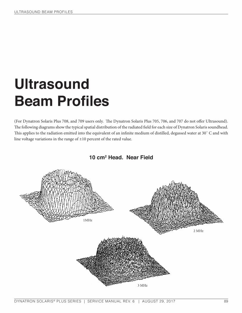
ulTrasound beaM ProfIles
DYNATRON SOLARIS® PLUS SERIES | SERVICE MANUAL REV. 6 | AUGUST 29, 2017 89
Ultrasound Beam Profiles(For Dynatron Solaris Plus 708, and 709 users only. The Dynatron Solaris Plus 705, 706, and 707 do not offer Ultrasound). The following diagrams show the typical spatial distribution of the radiated field for each size of Dynatron Solaris soundhead. This applies to the radiation emitted into the equivalent of an infinite medium of distilled, degassed water at 30˚ C and with line voltage variations in the range of ±10 percent of the rated value.
10 cm2 Head. Near Field
3 MHz
1MHz
2 MHz

ulTrasound beaM ProfIles
DYNATRON SOLARIS® PLUS SERIES | SERVICE MANUAL REV. 6 | AUGUST 29, 2017 90
5 cm2 Head. Near Field
2 cm2 Head. Near Field
1MHz
2 MHz
3 MHz
1MHz
2 MHz
3 MHz

CoMbInaTIon TheraPy InsTruCTIons
DYNATRON SOLARIS® PLUS SERIES | SERVICE MANUAL REV. 6 | AUGUST 29, 2017 91
Combination Therapy InstructionsThe following combination therapy instructions are for Dynatron Solaris® Plus 708 and 709 USERS ONLY. The Dynatron Solaris® Plus 705, 706, and 707 do not offer the Ultrasound feature.
Comboplus™
Dynatronics’ Comboplus feature means you have almost unlimited options in setting up a combination treatment with Solaris Plus. You can:
WARNING• DO NOT use combination therapy for underwater treatment. Placing active electrodes underwater poses a
serious hazard to the patient!
• Use VERY LOW STIM INTENSITY for COMBO treatments.
• Remember to observe all contraindications, warnings, precautions, and usage cautions for BOTH Ultrasound and Electrical Stimulation therapy when performing combination therapy.
• Since electrical current travels between the electrode and the soundhead during a COMBO treatment, the electrode should be placed in proximity with the treatment area. Do not place the electrode and soundhead in positions that will cause current to pass through contraindicated areas.
• Avoid removing the soundhead from the skin surface during “Stim Through Soundhead” treatments as this may cause a momentary interruption of Stim current which may be uncomfortable to the patient. The soundhead should remain in full contact of the skin until current output is stopped.
• Be alert for any sign of periosteal (bone) pain.
CoMbInaTIon TheraPy InsTruCTIons
DYNATRON SOLARIS® PLUS SERIES | SERVICE MANUAL REV. 6 | AUGUST 29, 2017 92
• Combine an Ultrasound treatment with the following electrotherapy modalities provided by this device: IFC, Premodulated, Biphasic, Russian, High Volt, or Microcurrent.
• Set up a combination treatment by using the ULTRASOUND output jack and the automatically selected default STIM channel. When using the 708 and 709, the Microcurrent Combo will always use Channel 1, and High Volt Combo treatments will default to the High Volt (Hi-Volt) channel.
A special “COMBO” lead wire is provided with the 708 and 709 with the standard accessories for this device to accommodate the ComboPlus feature. This lead wire is plugged into the selected STIM jack; then the banana end of the lead is connected to the COMBO input jack on the right-side of the device, and the pin end of the lead is connected to an electrode to be placed on the patient. It is important to note the channel selected by the device during setup and connect the lead wire to the correct channel before setting intensity for the treatment.
Stim Through the SoundheadWith combination therapy, the soundhead is used in place of one electrode for a Stim treatment; and electrotherapy current is delivered through the soundhead. This means that for a normal 2-electrode Stim treatment therapy, you would place one electrode on the patient and use the soundhead as the second electrode site to complete the setup. A patient lead wire designed to accommodate this setup is included in the Dynatron Solaris Plus standard accessory package for devices with Ultrasound and electrical stimulation capabilities.
During the treatment, the Stim current passes between the soundhead and the other electrode. At the same time ultrasonic waves are introduced into patient tissue through the soundhead. Avoid touching the electrode with the soundhead during the treatment, keep the soundhead in contact with the patient’s skin at all times, and keep the intensity low for the Stim current.
In order to set up a COMBO treatment, you must be familiar with setup instructions for both the electrotherapy modality to be used and Ultrasound as explained earlier in this manual. Also remember:
• When a modality indicator is highlighted GREEN, the treatment parameters for that output are displayed. Any changes you make to the parameters will affect that channel only.
• When a modality indicator light is highlighted YELLOW, the channel is active, but its parameters are not being displayed (in focus) and may not be modified at this time. To bring a treatment’s parameters into focus, you must first press the CHANNELS toggle key to select the treatment—the modality indicator will then become GREEN and modifications are allowed.
When setting up a combination treatment, observe all contraindications, warnings, and precautions for both therapies to be used.
REMEMBER: Use very low Stim intensities for all COMBO treatments!
CoMbInaTIon TheraPy InsTruCTIons
DYNATRON SOLARIS® PLUS SERIES | SERVICE MANUAL REV. 6 | AUGUST 29, 2017 93
• When using the 708 or 709, since Ultrasound and Stim share the TIME and INTENSITY displays during a combination treatment, you will need to carefully observe which modality is in focus when setting up or changing treatment parameters. You may toggle between the Stim and SOUND channel using the CHANNELS toggle key. The treatment timer does not begin until you press START after both modalities have been set up.
Combination Therapy Setup
1. Press the COMBO key on the 708 and 709. SOUND will be illuminated GREEN in the CHANNELS window and an automatically selected STIM channel will be illuminated in YELLOW. Other available channels not in use will be illuminated in WHITE.
2. Plug the combo lead wire into the active STIM channel jack of the 708 or 709. The banana connector end plugs into the COMBO input jack on the right-side of the unit. The pin end attaches to the dispersive electrode.
3. Apply the dispersive electrode to the patient
4. With SOUND illuminated GREEN, select parameters for the Ultrasound portion of the COMBO treatment following the instructions found in the manual.
5. Press START.
6. When using the 708 or 709 press the single-channel STIM option of your choice. The selected STIM channel’s illumination will change from YELLOW to GREEN and become the focus treatment. NOTE: If selecting a Stim channel, other than the default channel, the illuminated channel will change from WHITE to GREEN. The SOUND channel will now be illuminated YELLOW. Proceed to set up the STIM treatment following the modality instructions found in the manual.
Remember, Microcurrent must use Channel 1 and High Volt the designated HI-VOLT Channel. The system defaults to a PREMOD treatment selection unless another default therapy has been selected previously.
7. Apply the conductive gel to the Ultrasound treatment site now. Place the soundhead at the treatment site making good contact with the skin.
8. Raise the Stim intensity. KEEP THE STIM INTENSITY LOW! If the soundhead is in proper position and coupling is good, the patient will feel the current. If the patient does not feel the current, check to be sure coupling is good and make sure you have used ample conductive gel.
NOTE: Although parameters and settings are selected for ultrasound therapy, no ultrasound power will be delivered until you press START after both the ULTRASOUND and STIM modalities have been set up.

CoMbInaTIon TheraPy InsTruCTIons
DYNATRON SOLARIS® PLUS SERIES | SERVICE MANUAL REV. 6 | AUGUST 29, 2017 94
9. Press START. Both STIM and ULTRASOUND will be activated.
10. STOP.
When the treatment time has elapsed, the therapy to the patient stops and a tone sounds notifying you of the treatment end. Treatments in progress may be stopped at any time using one of the following methods.
ALL STOP: Press the STOP key to stop all treatments at all channels on the 708 and 709 devices. The output for the channel(s) selected is stopped (both STIM and SOUND channels), and the device then displays the beginning treatment parameters.
STOP ONE TREATMENT ONLY ( 708 AND 709 Plus): If you have more than one treatment in progress, stop one treatment by either of the following methods. First, press the CHANNELS toggle key to select SOUND or press the active STIM modality key, the channel’s light will be illuminated GREEN when selected. Once selected press and hold the FUNCTION key and press the STOP key. Or, REDUCE THE TREATMENT TIME TO ZERO. Press the Time down arrow until the Time display reaches zero. The device beeps when the time reaches zero.
Modify A TreatmentModifications to a treatment in progress may be made to both modalities used. See the instructions earlier in this manual for specific modification instructions for each modality.
Combination Default SettingsThe factory default for a COMBINATION TREATMENT is an Ultrasound treatment with a Premodulated treatment and the respective default settings for those two modalities.
In COMBO mode you can save new default treatment time and the preferred Stim modality. The Stim settings in a COMBO treatment are determined by the defaults of that modality. Separate Ultrasound default settings may be saved for the COMBO treatment which will not affect Ultrasound-only treatments.
If you save defaults during a COMBO treatment the following settings are saved:
• The Stim modality that is selected for the current COMBO treatment is saved as the default Stim treatment for COMBO.
• Ultrasound parameters for this setup are saved, and become the default Ultrasound settings for combination treatments only (non-combination Ultrasound treatments may have different default settings).
• The treatment time is saved as the default treatment time for combination treatments.
NOTE: Pausing a COMBO TreatmentIn COMBO mode, if a treatment is paused by any means (either by pressing the PAUSE key or as a result of a soundhead that has become too hot), the Ultrasound output is stopped and the treatment timer is paused. However, the Stim current continues to be delivered. Therefore, the pause condition should be corrected as quickly as possible and the treatment resumed, or the treatment should be stopped completely by pressing the STOP button.

dynaTron® TherMosTIM™ Probe
DYNATRON SOLARIS® PLUS SERIES | SERVICE MANUAL REV. 6 | AUGUST 29, 2017 95
Dynatron® ThermoStim™ ProbeAn accessory to the Solaris Plus, the ThermoStim Probe provides cold, heat, and electrical stimulation all in one tool. The multi-surface head with edges and corners optimizes ThermoStim transfer and tissue mobilization. With the ability to deliver three separate treatments simultaneously, the ThermoStim Probe saves significant treatment time.
FunctionalityThe ThermoStim Probe is designed to operate in conjunction with six separate Stim modalities: Premod, Interferential, Biphasic, Russian, Microcurrent, and High Volt.
During a Stim treatment, the probe takes the place of one of the electrodes. Stim current passes between the probe and the patient electrode while combined with heat or cold introduced into the patient’s tissue through the probe.
For example, with a normal bipolar (2 electrodes) Stim treatment, one electrode would be placed on the patient (this electrode should be twice the size of the treatment probe, minimal 2” x 4”) and the ThermoStim probe would be used as the second electrode to complete the set-up. A specially designed patient lead wire is included with the Dynatron ThermoStim probe. Heat or cold may be used separately without Stim as well.
WARNING• Avoid touching the patient electrode with the probe during a treatment.
• A conductive gel should be applied to the patient’s skin where the ThermoStim probe is to be applied to ensure ample conductance during the Stim treatment
• Maintain at least 50% of the probe face in contact with the patient at all times
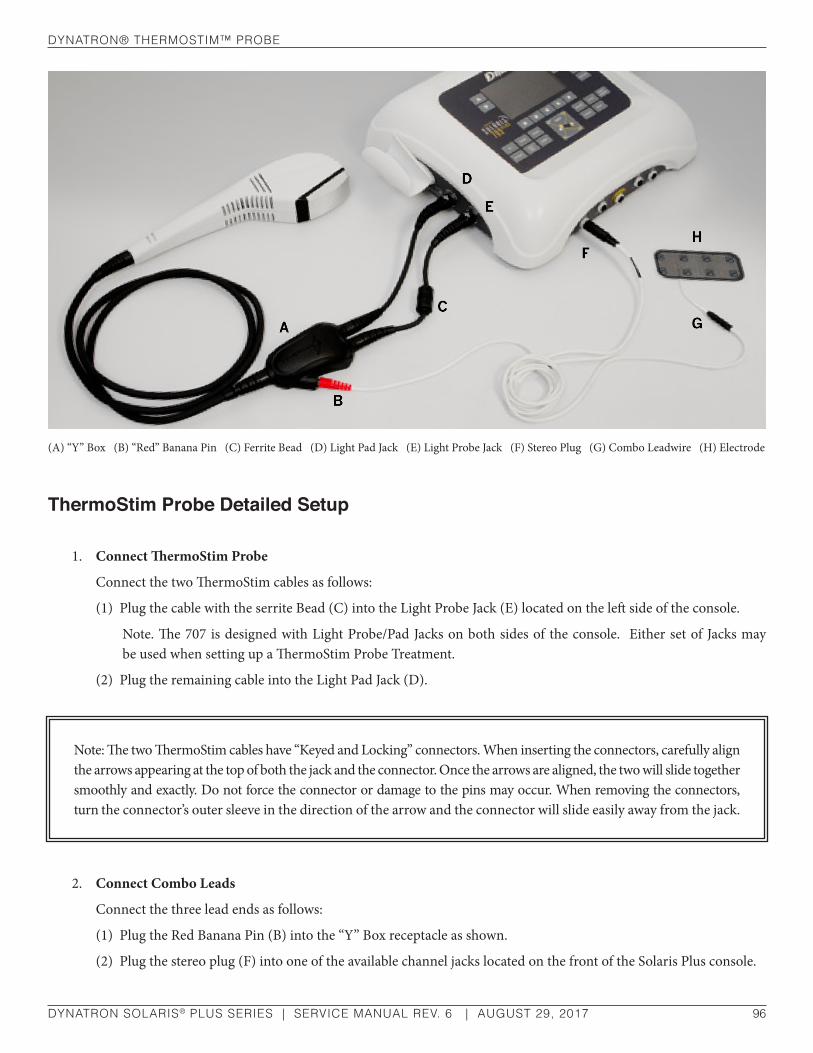
dynaTron® TherMosTIM™ Probe
DYNATRON SOLARIS® PLUS SERIES | SERVICE MANUAL REV. 6 | AUGUST 29, 2017 96
ThermoStim Probe Detailed Setup
1. Connect ThermoStim Probe
Connect the two ThermoStim cables as follows:
(1) Plug the cable with the serrite Bead (C) into the Light Probe Jack (E) located on the left side of the console.
Note. The 707 is designed with Light Probe/Pad Jacks on both sides of the console. Either set of Jacks may be used when setting up a ThermoStim Probe Treatment.
(2) Plug the remaining cable into the Light Pad Jack (D).
2. Connect Combo Leads
Connect the three lead ends as follows:
(1) Plug the Red Banana Pin (B) into the “Y” Box receptacle as shown.
(2) Plug the stereo plug (F) into one of the available channel jacks located on the front of the Solaris Plus console.
(A) “Y” Box (B) “Red” Banana Pin (C) Ferrite Bead (D) Light Pad Jack (E) Light Probe Jack (F) Stereo Plug (G) Combo Leadwire (H) Electrode
Note: The two ThermoStim cables have “Keyed and Locking” connectors. When inserting the connectors, carefully align the arrows appearing at the top of both the jack and the connector. Once the arrows are aligned, the two will slide together smoothly and exactly. Do not force the connector or damage to the pins may occur. When removing the connectors, turn the connector’s outer sleeve in the direction of the arrow and the connector will slide easily away from the jack.

dynaTron® TherMosTIM™ Probe
DYNATRON SOLARIS® PLUS SERIES | SERVICE MANUAL REV. 6 | AUGUST 29, 2017 97
(3) Plug the distal end of the leadwire (G) into a Return-Electrode that is at least 2” x 4”.
(4) Place the electrode on the patient’s skin proximal to the area being treated.
3. Apply Conductive Gel
Apply conductive gel to the skin in the area designated for the probe treatment.
4. Select PROBE On the Console
Using the Solaris Plus console, press the Modality Key labeled PROBE. Selections for setting up the ThermoStim treatment will appear in the Treatment Window. Treatments will default to “Hot,” Stim (Electrotherapy) “ON,” and the maximum temperature of (112° F).
CAUTION1. Do not allow gel to build up on the probe.
2. Using a soft cloth, remove all gel residue from the probe.
Pay particular attention to the vent openings.
3. Using a cotton-tipped applicator, clean the air vents carefully to prevent clogging and to ensure the proper operation of your probe.

dynaTron® TherMosTIM™ Probe
DYNATRON SOLARIS® PLUS SERIES | SERVICE MANUAL REV. 6 | AUGUST 29, 2017 98
Solaris Plus 707. Two ThermoStim probes can be operated simultaneously on the 707. If both probes are plugged into the console, the device will automatically default to the Probe on the left side of the console and TS PB1 will be highlighted in green in the Display Window. To change the focus to the probe on the right side, press the key under the Channels Window until TS PB2 is highlighted in green. Once selected, the options for setting up the ThermoStim treatment will appear in the Treatment Windows.
5. Setting Hot and Cold Intensity
Thermal Intensity can be set at any time after pressing PROBE. If a setting other than the default maximum Heat intensity of 112° F or Cold of 35° F is desired, adjustments can be made by using the arrow keys located next to the Intensity Window.
6. Hot and Cold Intensity Bars
Vertical Bars: Changes in Thermal Intensity are indicated by the vertical bars on the right-side of the display screen labeled INTENSITY. The maximum intensity (Blue = Cold 35° F/ Red = Heat 112° F) is displayed as 5 full vertical bars
If Intensity has been manually adjusted to a target range other than the maximum default, the number of vertical bars will reflect the change.
Horizontal Bar: The horizontal bar indicates the cooling or heating process taking place on the face of the probe. When the Horizontal Bar is full, the face of the probe has reached the minimum therapeutic level temperatures (Cold 60° F / Heat 90° F).
7. Select Treatment Parameters
The factory default settings of Hot, Stim (Electrotherapy), and Time may be changed by using the toggle keys under the MODE AND STIM windows and the arrow keys located next to the Time display.
Mode Window: Toggle until desired mode of Hot or Cold is illuminated.
Stim Window: Select “OFF” to select a only a Thermal treatment or “ON” for both Thermal and Stim.
Time Window: Treatment Time defaults to 10:00 minutes. Alternate Time settings may selected by using the arrow keys located next to the TIME display.
Note. Once PROBE is selected on the Solaris Plus console, or the right or left ThermoStim Probe has been selected on the 707, the Probe will immediately activate and start heating. If the default setting has been changed to Cold, the probe will begin to cool.
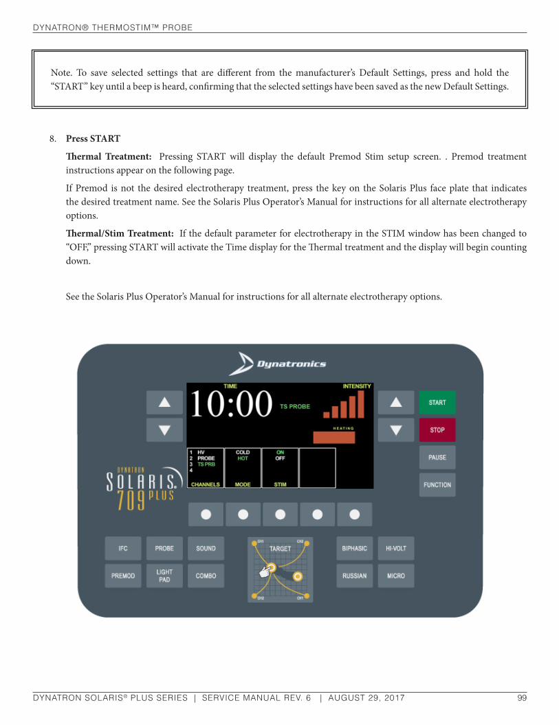
dynaTron® TherMosTIM™ Probe
DYNATRON SOLARIS® PLUS SERIES | SERVICE MANUAL REV. 6 | AUGUST 29, 2017 99
8. Press START
Thermal Treatment: Pressing START will display the default Premod Stim setup screen. . Premod treatment instructions appear on the following page.
If Premod is not the desired electrotherapy treatment, press the key on the Solaris Plus face plate that indicates the desired treatment name. See the Solaris Plus Operator’s Manual for instructions for all alternate electrotherapy options.
Thermal/Stim Treatment: If the default parameter for electrotherapy in the STIM window has been changed to “OFF,” pressing START will activate the Time display for the Thermal treatment and the display will begin counting down.
See the Solaris Plus Operator’s Manual for instructions for all alternate electrotherapy options.
Note. To save selected settings that are different from the manufacturer’s Default Settings, press and hold the “START” key until a beep is heard, confirming that the selected settings have been saved as the new Default Settings.

dynaTron® TherMosTIM™ Probe
DYNATRON SOLARIS® PLUS SERIES | SERVICE MANUAL REV. 6 | AUGUST 29, 2017 100
Using Stim With The ThermoStim Probe Premod Treatments SetupA Premodulated treatment uses one channel and two electrodes.
1. Select Channel
Using the Channels toggle key located beneath the Channels Window, select the channel into which the stereo plug (F) has been inserted. Channels 1,2 ,3, or 4 will become illuminated when selected.
2. Time
Set the treatment TIME. Default Treatment Time is 10 minutes.
3. Select RANGE
HIGH, LOW, ALT (high/low alternating), CONSEC ( ½ high, ½ low), or FIXED (select 4,000 to 10,000 Hz).
4. Intensity
With the ThermoStim Probe in contact with the patient’s skin, increase INTENSITY (patient will feel the current) using the arrow keys located next to the INTENSITY display. Do not increase INTENSITY beyond the patient’s comfort level.
5. Press START
The selected electrotherapy modality parameters will be displayed and Time will begin counting down.
TREATMENT NOTES
• Apply sufficient pressure so that at least 50% of the probe face will remain in contact with the patient’s skin at all times during treatment.
• All Contraindications, Warnings, and Precautions for Stim modalities apply when using the ThermoStim probe
• The ThermoStim Probe cannot be submerged in water
6. Press STOP
To stop a ThermoStim treatment prior to its completion, press and hold the FUNCTION KEY and press the STOP key. Pressing STOP alone stops all treatments operating on the device. Using the TIME arrow keys to bring a treatment time to zero will also stop a treatment.
7. Moving Between Stim and Thermal Displays
If a Premod or alternate electrotherapy treatment has been selected in combination with the Thermal treatment, the electrotherapy treatment screen will remain in focus after pressing START. To move between the Electrotherapy and Thermal display screens, press the Channels toggle key.

dynaTron® TherMosTIM™ Probe
DYNATRON SOLARIS® PLUS SERIES | SERVICE MANUAL REV. 6 | AUGUST 29, 2017 101
8. Saving Custom Default Parameters or Treatment Setups
After completing the treatment setup or after choosing new default parameters – but before pressing START to begin a treatment, PRESS and HOLD the START key until a tone sounds. The tone indicates that new Default settings have been saved, or that the ThermoStim treatment parameters are saved for future use.
Dynatron ThermoStim Specifications
Power Requirements ...............................................................................................................None
Power Consumption ................................................................................................................None
Fuse ............................................................................................................................................None
Dimensions ......................................................................................... 2” (W) x 3.6” (D) x 10” (L)
5.08 cm (W) x 9.14 cm (D) x 25.4cm (L)
Weight ...................................................................26.455 ounces or .1.653 pounds (750 grams)
CAUTIONTHERE ARE NO SERVICEABLE PARTS INSIDE THE DYNATRON THERMOSTIM PROBE.
WARNINGWHEN TREATING WITH THE THERMOSTIM PROBE, FOLLOW ALL CONTRAINDICATIONS, WARNINGS, AND PRECAUTIONS ASSOCIATED WITH THE ELECTRICAL STIMULATION TREATMENT USED IN COMBINATION WITH HEAT OR COLD.

sIMulTaneous TreaTMenTs
DYNATRON SOLARIS® PLUS SERIES | SERVICE MANUAL REV. 6 | AUGUST 29, 2017 102
Simultaneous TreatmentsThe Dynatron Solaris Plus allows many combinations of simultaneous treatments to be delivered at once using available channels. Simultaneous treatments are not the same as COMBO treatments. A COMBO treatment combines Ultrasound with a Stim therapy into a single treatment. A COMBO treatment is always delivered to one patient. Simultaneous treatments are independent treatments that are set up separately, that have separate treatment timers, and which may be delivered to one or more patients at the same time.
There are very few limitations to the simultaneous treatments that may be set up with the Dynatron Solaris Plus. You can set up any number of separate treatments as described below with the exceptions noted:
• Channels 1 through 4 may be used for any number of Interferential, Premodulated, Russian, or Biphasic treatments. For treatments using one channel, the device will select the next available channel. For treatments using two channels, the device will select a channel pair (1-2 or 3-4). Note: Channels 3-4 are available on Solaris Plus 706, 707, and 709 only.
• Whenever a Microcurrent, or Direct Current treatment is in progress (probe or electrodes), Channel 1 is unavailable for any other use. However, Channels 2, 3, and 4 may be used for other Stim treatments.
Set Up A Second TreatmentTo set up the second (or third) treatment, after you have set up and started the first modality, press the modality key for the second treatment to be set up. The device automatically selects the treatment channel(s) to be used. The GREEN channel light shows you the channel(s) selected for this treatment. Plug the lead or cable into the corresponding output jack(s) before you proceed with setting up the treatment. Select the treatment parameters for the second treatment following the setup instructions for that modality provided in this manual. When parameters have been entered, press START.

sIMulTaneous TreaTMenTs
DYNATRON SOLARIS® PLUS SERIES | SERVICE MANUAL REV. 6 | AUGUST 29, 2017 103
Modify Simultaneous TreatmentsYou may VIEW and MODIFY parameters for the treatment channel(s) that is illuminated GREEN. While two or more treatments may be in progress at once, the TIME / INTENSITY displays can show only the settings for the focus treatment whose operational channels are illuminated GREEN. Other channels in use at that time will be illuminated YELLOW indicating that the channels are active (delivering current) but their parameters are not currently displayed or in focus.
All channels that are currently operational but not in focus, are listed both in the CHANNELS window and in small font on the left-hand side of the Treatment Display Screen under the heading, RUNNING TREATMENTS. Included in the list under RUNNING TREATMENTS, is the active channel(s) illuminated in YELLOW; and the name of the treatment modality with the remaining treatment time, both illuminated in White.
To change the settings for a channel or output that has a YELLOW light, press the CHANNELS toggle key one or more times until the light for the desired channel becomes GREEN. The TIME and INTENSITY displays change to show the parameters currently in effect for that treatment. Once a treatment is in focus, the parameters may be changed.

ConTraIndICaTIons, WarnIngs, & PreCauTIons
DYNATRON SOLARIS® PLUS SERIES | SERVICE MANUAL REV. 6 | AUGUST 29, 2017 104
Contraindications, Warnings, & Precautionsfor Interferential, Premodulated, Russian, Biphasic, High Voltage Pulsed Stimulation, and Direct Current Treatments
ContraindicationsThrombosis. It is possible that the current produces chemical changes in the blood leading to alterations in the clotting time. At present there is no specific scientific evidence to support this. Nevertheless, treatment must not be given to any patient who is taking anticoagulants as it may render these ineffective. The effect of the current is on the platelets and would tend to spread any clot with perhaps fatal results in a patient with coronary thrombosis. If a patient has a history of deep vein thrombosis, even many years past, the treatment may increase rather than decrease swelling.
Implanted Electronic Devices. Patients with Implanted Electronic Devices (for example a cardiac pacemaker) should not be subjected to stimulation.
Cardiac Conditions. The electrodes should be placed to avoid the stellate ganglion and the heart itself. If there is a potential for heart problems, the clinician must exercise professional judgment and use adequate precautions. The clinician should not expose the patient to risk if possible heart problems are suspected.
Bacterial Infections. The effect on bacteria is uncertain, and it is advisable that bacterial infections should not be treated.
Malignancy. The use of Interferential, Premodulated, High Volt, Direct Current, Biphasic, or Russian Stim treatment is contraindicated in patients with clinically diagnosed cancer.
WARNINGThoracic applications are contraindicated: Additional warning from the Canadian Health and Welfare Department, Health Protection Branch. Cardiac fibrillation may occur if output current is 50 mA RMS or greater for any output circuit.

ConTraIndICaTIons, WarnIngs, & PreCauTIons
DYNATRON SOLARIS® PLUS SERIES | SERVICE MANUAL REV. 6 | AUGUST 29, 2017 105
Warnings
1. Adequate precautions should be taken in the case of persons with suspected or diagnosed epilepsy.
2. Severe spasm of the laryngeal and pharyngeal muscles may occur when the electrodes are positioned over the neck or mouth. The contractions may be strong enough to close the airway or cause difficulty in breathing.
3. Caution should be used in the transthoracic application of EMS devices in that the introduction of electrical current into the heart may cause arrhythmia.
4. This device should be kept out of the reach of children.
5. The Dynatron device should not be used in the following conditions:
• Pregnancy
• Acute and sub-acute thrombophlebitis
• Potentially malignant lesions
• Implants of any electrical nature
• Do not use over a carotid sinus
• Transcerebrally
• Disturbances in cardiac rhythm
6. The long-term effects of chronic electrical stimulation are unknown.
7. This device should not be used to relieve pain syndromes until etiology has been established.
8. Current densities for any electrodes exceeding 2 mA r.m.s./cm2 may require the special attention of the USER.
Precautions
1. Precautions should be observed following recent surgical procedures when muscle contractions may disrupt the healing process.
2. Some patients may experience skin irritation or hypersensitivity due to the electrical stimulation or electrical conductive medium. The irritation can usually be reduced by use of an alternate conductive medium or alternate electrode placement.

ConTraIndICaTIons, WarnIngs, & PreCauTIons
DYNATRON SOLARIS® PLUS SERIES | SERVICE MANUAL REV. 6 | AUGUST 29, 2017 106
3. Interferential, Premodulated, Biphasic, Russian, Direct Current and High Volt therapy must be used cautiously in the presence of any of the following conditions:
• When there is a tendency to hemorrhage following acute trauma or fracture.
• Over the menstruating uterus.
4. Use extreme caution when administering a treatment where sensory nerve damage is present or in any case where there is a loss of normal skin sensation; this includes areas desensitized by medication or ice. When treating an area where there is loss of feeling, there is an increased danger of injuring the patient. Do not treat such areas unless you have sufficient training and experience in applying this therapy for such cases and you are confident you can deliver the treatment safely without injuring the patient.
When treating any conditions contributing to loss of sensation, or any time the patient cannot feel the electrical stimulation, do not exceed an intensity setting of 12-15 when using large electrodes (3-3/4” x 1-3/4”) or an intensity setting of 8-10 when using small electrodes (1-3/4” x 1-3/4”), and select short treatment times (approximately 8 minutes). Be alert for any irregularities in the skin following the treatment.
Never use High Volt therapy to treat an area where there is a loss of normal skin sensation.
5. Do not use in general area where high-powered, high-frequency transmitting surgical units are being operated. Short wave diathermy should not be turned on or used at the same time as this Dynatron device.
6. Do not use the same power outlet or line with a whirlpool and certain traction machines. In areas which are carpeted and static electricity is present, it may be necessary to use a conductive mat or anti-static carpet treatment to remove any static charge from the operator before touching the device.
7. To avoid causing possible interference with the operation of the Dynatron device, it should not be connected to anyone who is wearing or holding an RF transmission device (two-way radio, cell phone, beeper, etc.)
Treatment Setup Warnings
1. NEVER turn the power on or off while the unit is connected to the patient.
2. Always STOP a treatment before removing or attaching electrodes or leads to the patient. Leads and electrodes must only be applied to the patient before a treatment is started.
3. Never use worn or damaged leads or electrodes as these may result in injury to the patient. Check leads using the Lead Test function provided by this device.
4. Electrodes must be attached and probe placed in contact with the patient’s skin (if applicable) prior to starting a treatment.

ConTraIndICaTIons, WarnIngs, & PreCauTIons
DYNATRON SOLARIS® PLUS SERIES | SERVICE MANUAL REV. 6 | AUGUST 29, 2017 107
Adverse EffectsSkin irritation and burns beneath the electrodes have been reported with the use of electrotherapy.
Any electrical stimulation has the potential to burn or irritate a patient’s skin. The tendency towards burning is dependent upon several factors; the most important being patient susceptibility and current density. The practitioner has little control over patient susceptibility, other than to observe first time patients carefully. However, current density is totally controllable. It is important to note that the intensity displayed is not a measurement of the current delivered. For Interferential, Premodulated, Biphasic and Russian Stim, this is a relative reading only. Current delivered at a given intensity setting is dependent upon the current setting, the size and type of electrodes used, and conductance.
Current density is the amount of current delivered, divided by the area through which the current is being delivered. Higher current density increases the tendency to burn or irritate. The current density can be reduced by decreasing the amount of current or increasing the area through which the current is being delivered. The area can be increased by using larger electrodes and/or making sure that the total area of the electrode is actually delivering current. Current density is also reduced when more electrodes are used (four instead of two).
Electrodes which are worn or have lost their adhesiveness, or carbon electrodes which are corroded and are not securely fastened, fail to deliver current evenly as required. These kinds of electrodes may have “hot spots” where higher than normal current density will be delivered. If the patient complains of “pin prick” sensations, the electrode may be delivering current through only a small portion of its area, and the electrode should be replaced. Also see “Electrotherapy Usage Cautions” in this manual for further discussion regarding safe use of leads and electrodes.
Use Only Dynatronics AccessoriesThe leads and electrodes provided by Dynatronics have been tested with Dynatronics devices and are appropriate for use with these devices. Dynatronics cannot guarantee the safety or performance of leads and electrodes purchased from other vendors.
Only use electrodes which are designed for use with this device. NEVER use monitoring electrodes such as ECG, EKG, or EMG. NEVER use electrodes specified only for TENS devices as those electrodes may not be adequate for use with the electrotherapies provided by this device.
Contact Dynatronics Customer Service if you have questions about appropriate electrodes for use with this device.
ConTraIndICaTIons, WarnIngs, & PreCauTIons for MICroCurrenT
DYNATRON SOLARIS® PLUS SERIES | SERVICE MANUAL REV. 6 | AUGUST 29, 2017 108
Contraindications, Warnings, & Precautions for Microcurrent
ContraindicationsThe following treatment conditions are specifically contraindicated for MICROCURRENT, and must be excluded:
1. Any electrode placement that applies current to the carotid sinus (neck) region.
2. Any use of TENS on patients who have a demand-type cardiac pacemaker or an implanted electronic device.
3. Any electrode placement that causes current to flow transcerebrally (through the head).
4. The use of TENS whenever pain syndromes are undiagnosed, until etiology is established.
Warnings
1. The safety of TENS devices for use during pregnancy or delivery has not been established.
2. TENS is not effective for pain of central origin. (This includes headache.)
3. TENS devices should be used only under the continued supervision of a physician.
4. TENS devices have no curative value.

ConTraIndICaTIons, WarnIngs, & PreCauTIons for MICroCurrenT
DYNATRON SOLARIS® PLUS SERIES | SERVICE MANUAL REV. 6 | AUGUST 29, 2017 109
5. TENS is a symptomatic treatment and as such suppresses the sensation of pain which would otherwise serve as a protective mechanism.
6. Electronic monitoring equipment (such as ECG monitors and ECG alarms) may not operate properly when TENS stimulation is in use.
7. This device should be kept out of the reach of children.
8. Isolated cases of skin irritation may occur at the site of electrode placement following long-term application.
9. Effectiveness is dependent upon patient selection.
10. Some patients may experience skin irritation or hypersensitivity due to the electrical stimulation or electrical conductive medium. The irritation can usually be reduced by use of an alternate conductive medium or alternate electrode placement.
PrecautionsThis therapy must be used cautiously in the presence of any of the following conditions:
• When there is a tendency to hemorrhage following acute trauma or fracture.
• Over the menstruating uterus.
• Where sensory nerve damage is present or in any case where there is a loss of normal skin sensation; this includes areas desensitized by medication.
• Do not use in general area where high-powered, high-frequency transmitting surgical units are being operated. Short wave diathermy should not be turned on or used at the same time as this Dynatron device.
• Do not use the same power outlet or line with a whirlpool and certain traction machines. In areas which are carpeted and static electricity is present, it may be necessary to use a conductive mat to remove any static charge from the operator.
Adverse ReactionsSkin irritation and burns beneath the electrodes may occur with Microcurrent treatment.
NOTE: When using Microcurrent Frequencies and intensities, it is extremely unlikely that a burn may occur. However, this possibility exists under certain circumstances. For example, if a high current setting is combined with poor electrode quality and/or high current density (small current delivery area). Monitor the patient’s comfort throughout the treatment and change treatment settings if the patient finds the treatment intolerable.

ConTraIndICaTIons, WarnIngs, & PreCauTIons for ulTrasound TreaTMenT
DYNATRON SOLARIS® PLUS SERIES | SERVICE MANUAL REV. 6 | AUGUST 29, 2017 110
Contraindications, Warnings, & Precautions for Ultrasound Treatment
ContraindicationsThe Dynatron Solaris Plus Ultrasound should not be applied in the following CONDITIONS:
• Pregnancy
• Acute and sub-acute thrombosis and thrombophlebitis
• Potentially malignant lesions, tumors malignant or benign
• Areas or lumps that may be suspected as cancerous or precancerous
• Third degree musculo-tendonous lesions
• Cardiac pacemaker or other implanted electronic device
• Implants of any electrical nature
• Skin diseases
• Multiple sclerosis
• Osteomyelitis
• Disturbances in cardiac rhythm
• Tissue or bone with acute sepsis
• Arteriosclerosis or weakened blood vessels

ConTraIndICaTIons, WarnIngs, & PreCauTIons for ulTrasound TreaTMenT
DYNATRON SOLARIS® PLUS SERIES | SERVICE MANUAL REV. 6 | AUGUST 29, 2017 111
• Hemophilia
• Where sensory nerve damage is present with a loss of normal skin sensation.
The Dynatron Solaris Plus Ultrasound should not be applied to the following AREAS:
• Transcerebrally
• To the eye
• To the ear
• Over a carotid sinus
• To the heart
• To major subcutaneous nerves and blood vessels
• To the spinal cord
• Around the bulbar area of the spinal cord
• To reproductive organs
• Over viscera (stomach, spleen, liver)
• Over epiphyseal areas of the bones in growing children
• Over stellate ganglion and subcutaneous major nerves
• To tissues previously treated by deep x-ray or other radiation
• Over the joint capsule in acute or sub-acute arthritic conditions
• Over ischemic tissue in patients with vascular disease
• Over a laminectomy site
• Over total joint replacements (the effect of Ultrasound on the new plastics is unknown)
The Dynatron Solaris Plus Ultrasound should not be used over healing fractures.
PrecautionsThe Dynatron Solaris Plus Ultrasound devices must be used cautiously in the presence of any of the following conditions:
• When there is a tendency to hemorrhage following acute trauma or fracture.
• Acute bursitis. Do not use in continuous duty cycle mode.
INTENSITY (POWER) SHOULD BE REDUCED IF PATIENT COMPLAINS OF PERIOSTEAL BONE PAIN (BONE ACHE)
ConTraIndICaTIons, WarnIngs, & PreCauTIons for ulTrasound TreaTMenT
DYNATRON SOLARIS® PLUS SERIES | SERVICE MANUAL REV. 6 | AUGUST 29, 2017 112
Warnings• Do not use in general area where high-powered, high-frequency transmitting surgical units are being operated.
Short wave diathermy should not be turned on or used at the same time as this Dynatron device.
• Do not use the same power outlet or line with a whirlpool and certain traction machines.
• In areas which are carpeted and static electricity is present, it may be necessary to use a conductive mat to remove any static charge from the operator. Use a surge suppressor if power problems are encountered.
• Avoid unnecessary exposure to Ultrasound (patient and therapist).

ConTraIndICaTIons, WarnIngs, & PreCauTIons for TrI-WaVe lIghT TreaTMenTs
DYNATRON SOLARIS® PLUS SERIES | SERVICE MANUAL REV. 6 | AUGUST 29, 2017 113
Contraindications, Warnings, & Precautions for Tri-Wave Light Treatments
ContraindicationsDo not use:
• Cancer (tumors or cancerous areas)
• Direct irradiation of the eyes
• Treatment of patients with idiopathic photophobia or abnormally high sensitivity to light
• Patients that have been pre-treated with one or more photosensitizers
• Direct irradiation over the fetus or the uterus during pregnancy
• Direct irradiation of the thyroid gland and endocrine glands
CAUTIONThe Solaris Plus Tri-Wave Light Probes and Pads should be plugged into the appropriate output jacks, only when the Solaris Plus device is turned OFF.

ConTraIndICaTIons, WarnIngs, & PreCauTIons for TrI-WaVe lIghT TreaTMenTs
DYNATRON SOLARIS® PLUS SERIES | SERVICE MANUAL REV. 6 | AUGUST 29, 2017 114
Precautions and Warnings
• Caution, the use of controls or adjustments of performance or procedures other than those specified herein may result in hazardous radiation exposure.
• Read all instructions, precautions, and contraindications carefully before beginning treatments.
• If the treatment area is larger than the size of the Probe aperture, then areas equal in size to the aperture should be treated one at a time until the entire area is covered. Do not attempt to “bathe” the area by moving the Probe back and forth or in some other manner over the target area. Failure to make full contact with the treatment surface may result in outcomes that are less effective. Other methods may reduce total energy absorption. If the area is large, the TWO 5” X 7” Tri-Wave Light Pads may be a more appropriate treatment option.
• DO NOT use over open wounds unless covered with a clear sterile protective barrier. An open wound may be treated in the non-contact mode without protective barrier however energy delivery will be diminished. Undue pressure should not be exerted on the wound bed. Caution: The probe should also be sanitized, e.g. by cleaning with methylene (alcohol) or some other standard sanitizing agent.
• DO NOT USE ISOPROPYL ALCOHOL WHEN CLEANING THE TRI-WAVE PROBE LENS. To cleanse, use a mild antibacterial soft soap and lukewarm water on a soft cloth. Never apply soap and water directly on the lens. Gently rinse using the soft cloth damped with clean lukewarm water. Dry by blotting with a damp cloth or chamois.
• Cleanse the Tri-Wave Light Pad by gently wiping the surface with a mild soap on a dampened soft cloth. Never immerse the pad. Alcohol, caustic cleansers, or solvents should never be used on the pad’s surface.
• Cleanse the treatment area thoroughly in order to remove all gels and lotions.
• DO NOT use gels or lotions in combination with light therapy. Using gels will obscure the optical output resulting in a loss of output power and efficacy. Gels will clog the vents causing overheating and damage to the internal components. Damage caused by the use of gels and lotions may void your warranty.
• Keep the Tri-Wave Light Probe head vents unobstructed during treatment.
WARNINGProtective eyewear is required when using the Blue Light options. Exposure to blue light poses a risk of eye (retinal) damage.
NOTE: This therapy must be used cautiously where sensory nerve damage is present or in any case where there is a loss of normal skin sensation; including areas desensitized by medication or other therapies such as any type of cryotherapy.

ConTraIndICaTIons, WarnIngs, & PreCauTIons for TrI-WaVe lIghT TreaTMenTs
DYNATRON SOLARIS® PLUS SERIES | SERVICE MANUAL REV. 6 | AUGUST 29, 2017 115
• DO NOT use the Tri-Wave Light Probes or Pads underwater.
• Avoid use over areas recently injected with or exposed to steroids.
• A potential exists for skin irritation, rash, itching, scaling swelling, burning and erythema. Discontinue use if pain, inflammation, rash, skin irritation or discomfort persists.
• Patients who are taking medications which increase light sensitivity may have adverse reactions. Consult a physician to determine the photosensitizing characteristics of a specific drug.
• Caution should be used in handling the Tri-Wave Light Probes and Pads to avoid inadvertent exposure to the eyes.
• Do not view with optical instruments or magnifiers. Avoid viewing light probes or pads with light gathering instruments such as: binoculars, cameras, and telescopes.
• There are no serviceable parts inside the Tri-Wave Light Probes or Pads.
• Use of cellular phones in the vicinity of sensitive electronic devices may cause interference and device malfunction.
• Do not point the activated probe or pads at other people.
• Tri-Wave probes or pads are not to be opened by user. The user is not to modify the unit or remove protective covers or housings. There are no user serviceable parts.
• Service is not to be performed other than by factory authorized personnel.

dynaTron solarIs® Plus desCrIPTIons and dIagraMs
DYNATRON SOLARIS® PLUS SERIES | SERVICE MANUAL REV. 6 | AUGUST 29, 2017 116
Dynatron Solaris® Plus Descriptions and Diagrams
Dynatron® Solaris™ Plus Description• The Main Board provides routing for communications and power to all boards in the system
• The CPU uses an Analog Devices Blackfin processor and Flash memory to control the resources located on the various treatment boards and to communication with the User Interface board
• The Light Mezzanine controls the Light Pad and Light Probe
• The STIM 1-2 board connects directly to the Main board and has pass through connections from the Main for the Ultrasound board and the STIM 3-4 board
• The STIM 1-2 board communicates and provides output signals to the STIM 3-4 board
• The SD card interface allows for field updates of the Operating software to the CPU
• The Display / Keyboard provides for the User Interface (cap sense switches) and drives the liquid crystal display for user feedback
Dynatron® Solaris™ Plus Block Diagram
Main BoardCPU
LightMezzanine
STIM 1 – 2Board
Keypad / DisplayBoard
SD CardInterfacePower
Supply
STIM3 – 4
UltrasoundBoard
Block Diagram

dynaTron solarIs® Plus desCrIPTIons and dIagraMs
DYNATRON SOLARIS® PLUS SERIES | SERVICE MANUAL REV. 6 | AUGUST 29, 2017 117
Hardware ConfigurationsM
odel
CPU
Mai
n
STIM
1-2
STIM
3-4
Ultr
asou
nd
3WL
Driv
er
Key
boar
d
LCD
Driv
er
SD U
pdat
e
Pow
er
Supp
lies
d719 X X X X X X X X X 150W
d719 X X X X X X X X 150W
d716 X X X X X X X X 150W
d715 X X X X X X X 150W
Modality Configurations
Mod
el
IFC
Prem
od
Rus
sian
Bip
hasi
c
Ultr
asou
nd
Hi V
olt
DC
Mic
roC
urre
nt
Mul
ti-St
im Tr-Wave Light
Probe Pad
d719 X X X X X X X X optional optional optional
d719 X X X X X X X X optional optional optional
d716 X X X X X X X optional optional optional
d715 X X X X X X X optional optional optional

ProCessor InTeraCTIon
DYNATRON SOLARIS® PLUS SERIES | SERVICE MANUAL REV. 6 | AUGUST 29, 2017 118
Processor Interaction
Processor Interaction with the Keyboard and DisplaysThe keyboard is controlled by a microcontroller which scans the cap sense for key presses, keeps the display updated, and reads any position from the XY pad. Periodically (several times per second) the main processor polls the keyboard processor, receiving status of any keys pressed or XY position touch and updates the display as required.
Processor Interaction with OscillatorsThe main processor controls the internal oscillators that generate the therapy wave forms. It initially calibrates the proper output frequencies during the test cycle, and then keeps track of the frequency the rest of the time the unit is on. If the oscillator happens to drift too far out of range for the processor to calibrate it, the processor will give an error message.
During the treatment, the processor causes the sweep frequency oscillator to change its frequency at a controlled rate. It chooses the rate and frequency from what is selected on the keyboard when the treatment is set up, or when changes are made during the treatment. It tracks and keeps the fixed frequency where it should be during the treatment. It also keeps track of the 2500 Hz signal that creates the Russian therapy (turns it on and off at a 50 Hz rate).
Oscillators
1. 4 KHz fixed
2. 4000-4010 Hz (Interferential Low option)
3. 4080-4150 (Interferential High option)
4. 2500 Hz (Russian)
5. 4000-10,000 (Fixed Frequency)

ProCessor InTeraCTIon
DYNATRON SOLARIS® PLUS SERIES | SERVICE MANUAL REV. 6 | AUGUST 29, 2017 119
Processor Interaction with the Output JacksThe processor board controls the proper channeling of the output signals to the output jacks. The processor also activates and monitors the relay that allows output from the unit.
Processor Control of Output WaveformsThe output waveforms are generated by a Digital Signal Processor on command from the main processor. Since the signals are digitally created, the accuracy of the waveform is derived from the crystal clock of the processor, whose accuracy is typically .001% or better. Both the output intensity as well as the frequency are digitally controlled through communication between the main processor and the Digital Signal processors.

general sPeCIfICaTIons
DYNATRON SOLARIS® PLUS SERIES | SERVICE MANUAL REV. 6 | AUGUST 29, 2017 120
General SpecificationsOther ranges, accuracy and precision values that are not provided here may be obtained from Dynatronics upon request.
Dynatron Solaris Plus Specifications
Power Requirements ................................................................................. 100-240 V~, 50/60 Hz
Power Consumption ........................................................................................................100 Watts
Fuse: ............................................................................................... 120 VAC: 250 V, 5A slow blow
240 VAC: 250 V, 2.5A slow blow
Dimensions .......................................18.5” W (47 cm) x 4.0” H (10.2 cm) x 12.0” D (30.5 cm)
Weight ..............................................................................................................8.2 pounds (3.7 Kg)
Environmental ConditionsTransport and Storage
This equipment, while packed for transport or storage, should not be exposed to environmental conditions outside the following ranges:
a. an ambient temperature range of -40°C
b. a relative humidity range of 10% to 100% including condensation
c. an atmospheric pressure range of 500 hPa to 1060 hPa
+70°C

general sPeCIfICaTIons
DYNATRON SOLARIS® PLUS SERIES | SERVICE MANUAL REV. 6 | AUGUST 29, 2017 121
Operation
This equipment is designed to operate in normal use under the following environmental conditions:
a. an ambient temperature range of +10°C
b. a relative humidity range of 30% to 75% including condensation
c. an atmospheric pressure range of 700 hPa to 1060 hPa
Safety Features of the Dynatron Solaris• Double redundancy protection on output amplifiers.
• Current sensing. If current reaches the current limit for the device, intensity is automatically reduced.
• All intensity levels are automatically set to zero at the end of treatment (ensures proper setting of intensity levels for the next patient).
• Internal surge protection protects against line noise, machine switching operation and any other type of interference that could cause patient discomfort.
• Soundhead temperature monitoring prevents the soundhead from becoming too hot, both to protect the soundhead crystal from damage and to ensure patient comfort.
Care and Cleaning InstructionsSolaris Plus Console
• Clean the outer surface of the Dynatron Solaris Plus devices with a slightly damp or lightly moistened cloth. Mild household cleaners work well on the frame, but do not use cleaners on the display windows. Do not spray the solution directly on the unit.
• First moisten the cloth and then wipe the unit off. Solvents, caustic solutions and harsh or abrasive cleaners must never be used.
• Do not attempt to sterilize the device or its probes or pads, using any type of sterilization equipment including autoclaves.
• Avoid stretching cords to full length, bending cords sharply or wrapping cords tightly. Undue stress on cords can damage connections.
• Keep all food and drinks away from the machine and its accessories; spills can cause costly damage to the machine and repairs for this type of damage are not covered by the warranty.
• Do not drop the unit, probe, or the soundheads as severe damage will occur.
+30°C

general sPeCIfICaTIons
DYNATRON SOLARIS® PLUS SERIES | SERVICE MANUAL REV. 6 | AUGUST 29, 2017 122
Tri-Wave Light Probe and Pads
• DO NOT USE ISOPROPYL ALCOHOL WHEN CLEANING THE TRI-WAVE LIGHT PAD OR PROBES. To cleanse the probe and pad, use a mild (non caustic) antibacterial soft soap and lukewarm water on a soft cloth. Never apply soap and water directly on the lens. Gently rinse using the soft, cloth damped with lukewarm water. Dry by blotting with a damp cloth or chamois. If seeking a commercial cleanser or disinfectant it is recommended that a product be a disinfectant wipe containing only the following active ingredients:
Ultrasound Head
• Ultrasound heads should be cleaned with warm water. Always keep the head free from gel buildup. Alcohol may be used to sterilize the soundhead.
• Do not use ice water for cooling soundheads. Do not allow soundheads to overheat repeatedly. This could result in thermal shock to the crystal. Damage of this type is not covered by the warranty.
ThermoStim Probe
• Clean the ThermoStim Probe after each use.
• Using a soft cloth, remove all gel residue from the probe.
• Using a cotton-tipped applicator, clean the air vents carefully to prevent clogging and to ensure the proper operation of the probe. Pay particular attention to the vent openings.
Suggested Maintenance ScheduleService To Be Performed By A Technician:
Every 6 Months
• Test leads and carbon electrodes. Lead resistance should be less than 10% above the mean cable resistance. Greater values indicate strand breakage and lead should be replaced.
Annually
• Annual Ultrasound calibration should be performed by a qualified technician.
• Check the output voltages and currents on all outputs.
• Inspect soundhead connectors on unit and on soundhead.
• Verify DAC calibration and current limits.
• It is recommended that the Solaris Plus device be sent to the manufacturer for annual calibration including the Solaris Plus Tri-Wave Light Therapy Probes.
OctylDecyl Dimethyl Ammonium Chloride
Dioctyl Dimenthyl Ammonium Chloride
Dimenthyl Benzyl Ammonium Chloride
Didecyl Dimenthyl Ammonium Chloride
Alkyl (C14 50%; C12 40%; C16 10

general sPeCIfICaTIons
DYNATRON SOLARIS® PLUS SERIES | SERVICE MANUAL REV. 6 | AUGUST 29, 2017 123
Maintenance Performed By User:
1. Inspect accessories daily for wear and damage. Examine cables and connectors on the cables for any visible sign of wear or damage. Replace accessories as needed:
• Replace lead wires and carbon electrodes at least every six months.
• Replace self-adhesive electrodes after not more than 15 uses.
2. Examine Ultrasound heads periodically for cracks which may allow ingress of conductive fluid.
3. If a machine or soundhead is dropped, or if it sustains damage due to lightning, severe power surge, submersion in water, or other incident that could cause damage to electronic components, the device must be examined by a Dynatronics technician before being returned to clinical use.
4. For older devices contact Dynatronics or your Dynatronics dealer for information and pricing for current upgrades to your device. Even if the machine is functioning properly, you can send it to Dynatronics for preventative maintenance service for a nominal charge; call for pricing.
5. Inspect device air vents periodically to ensure air flow is not blocked. An ordinary household vacuum hose may be used to clean dust from air vents externally.
6. There are no serviceable parts in the Solaris Plus Tri-Wave Light probes or pads. DO NOT attempt to unscrew or tighten down the bezel that holds the probe lens in place. This is not a threaded part.
7. Immediately report any device malfunction to Dynatronics Customer Service Department.
WARNINGHazardous electrical output. To reduce the risk of electrical shock, do not remove cover. Refer servicing to qualified service personnel.
CAUTION
For continued protection against risk of fire, replace fuses only with type IEC 127. For 120VAC supply, use 250W, 5A slow-blow. For 240VAC supply, use 250 V, 2.5A slow-blow.
NOTE: BEFORE sending a device to Dynatronics for service, you must FIRST obtain a return authorization number. Call Dynatronics’ Customer Service Department at (800) 874-6251 and discuss any problems or required service to save time and ensure the machine is returned to you as quickly as possible. See Section below “Returning a Unit for Repair.”

general sPeCIfICaTIons
DYNATRON SOLARIS® PLUS SERIES | SERVICE MANUAL REV. 6 | AUGUST 29, 2017 124
Software UpdatesWhen Software updates to the Solaris Plus devices become available, updates can be made quickly and easily by completing the following steps:
1. Turn off the console.
2. Insert the SD card supplied by Dynatronics into the SD CARD slot on the back of the console (fingers of the SD card facing up, label side down).
3. Turn on the console. There will be a 3 to 4 second pause while the card syncs with the Solaris Plus system software. A RED screen will appear with the following warnings: “DO NOT DISCONNECT POWER,” “DO NOT TURN OFF”
4. Press START to begin the download. Follow the instructions on the screen.
5. Remove the SD card from the SD CARD slot by gently pressing on the card. Turn off the console.
Solaris Plus Software Update Screens
NOTE: All custom defaults will remain effective after the new software is downloaded.
CAUTIONThe download process erases the device memory. If the download process is stopped for any reason prior to completion, call Dynatronics for further instructions.

general sPeCIfICaTIons
DYNATRON SOLARIS® PLUS SERIES | SERVICE MANUAL REV. 6 | AUGUST 29, 2017 125
Routine Ultrasound Calibration Inspections for Solaris PlusGovernment agencies regulate the frequency at which Ultrasound units must have their calibration checked. The device must still be examined at the periodic intervals specified by the governing agency for the country in which the device is used. To have the inspection performed by Dynatronics contact Dynatronics’ Customer Service Department. The device will need to be shipped to Dynatronics for the inspection. As an alternative, these periodic checks may be performed in your own locale by an independent contractor who is expert in checking the calibration of Ultrasound equipment. The calibration procedure MUST be performed by a qualified Ultrasound technician using the proper equipment, and is recommended every 6 to 12 months. Returning a Unit for Repair
Return AuthorizationIf it becomes necessary to return a Solaris Plus unit for repair, contact Dynatronics’ Customer Service (800) 874-6251. All returns must have a Service Order Number (SVO). The following information will need to be supplied when calling Dynatronics’ Customer Service to obtain a return Service Order Number (SVO):
1. User name and address
2. User phone number
3. Serial number of the unit
4. A description of the problem with the unit
After receiving the Service Order Number (SVO), the number should be clearly written on the outside of the shipping container.
Packaging and Shipping of Replacement Parts
All defective or broken parts should be shipped back to Dynatronics in the original shipping container. These containers are designed to withstand the punishment of shipping. If the original containers are not usable, find containers that are similar in protection so damage in shipping will be prevented. The person or company sending the unit to Dynatronics is responsible for any shipping damage resulting from a poorly packaged part or unit.
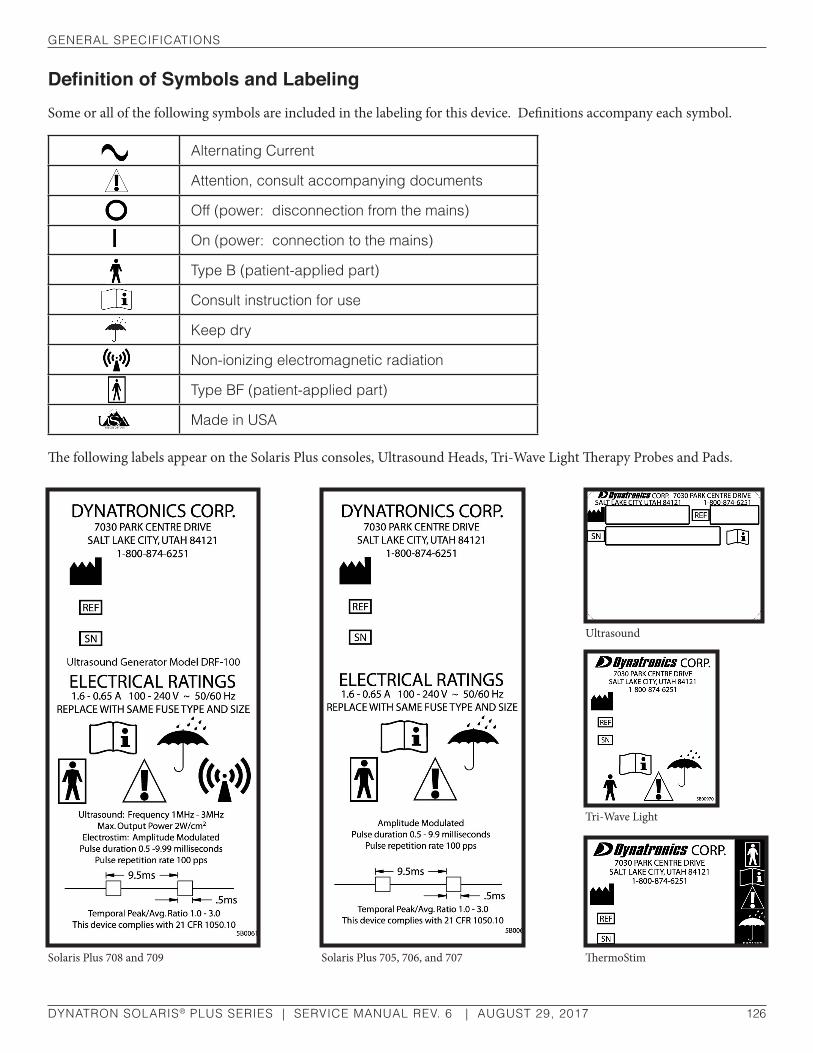
general sPeCIfICaTIons
DYNATRON SOLARIS® PLUS SERIES | SERVICE MANUAL REV. 6 | AUGUST 29, 2017 126
Definition of Symbols and LabelingSome or all of the following symbols are included in the labeling for this device. Definitions accompany each symbol.
alternating Current
attention, consult accompanying documents
off (power: disconnection from the mains)
on (power: connection to the mains)
Type b (patient-applied part)
Consult instruction for use
Keep dry
non-ionizing electromagnetic radiation
Type bf (patient-applied part)
Made in usa
The following labels appear on the Solaris Plus consoles, Ultrasound Heads, Tri-Wave Light Therapy Probes and Pads.
Solaris Plus 705, 706, and 707
Tri-Wave Light
Ultrasound
ThermoStim Solaris Plus 708 and 709
general sPeCIfICaTIons
DYNATRON SOLARIS® PLUS SERIES | SERVICE MANUAL REV. 6 | AUGUST 29, 2017 127
Equipment ClassificationThis device is classified as follows:
• Protection against electric shock: Class I (protectively earthed enclosure)
• Protection against electric shock: Type BF (floating patient-applied part)
• Protection against harmful ingress of water: none
• Equipment not suitable for use in the presence of a flammable anesthetic mixture with air or with oxygen or nitrous oxide.
• Mode of operation: Continuous operation
Disposal of Equipment and AccessoriesThere is no risk posed in disposal of this equipment or its accessories. These items contain no hazardous materials. For disposal of accessory batteries, see manufacturer’s instructions and follow applicable laws and regulations in your area.

TeChnICal suMMary
DYNATRON SOLARIS® PLUS SERIES | SERVICE MANUAL REV. 6 | AUGUST 29, 2017 128
Technical Summary
Setting DefaultsEach of the modalities has default settings that are automatically selected when a modality key is pressed. The default settings feature allows previously used treatment parameters to be set up in just seconds. For guidance in selecting the appropriate settings for each modality, consult published medical literature.
Save New DefaultsIf your most common treatment settings are different than the ones already set for this device, you can change the defaults to suit your own preferences. Setting new defaults is simple and defaults may be changed again and again whenever needed.
1. Press the modality key desired (IFC, Premod, Russian, Biphasic, High Volt, Micro, Direct Current, Sound, or Combo).
2. Set up a treatment using your preferred settings.
3. If this is an actual treatment you may increase the intensity now (intensity is not saved with the default settings). This step is optional.
CAUTION• Do not use Ohm meters on Solaris Plus devices. Ohm meters will damage the Solaris Plus processors.
• There are no serviceable parts in the Solaris Plus devices.

TeChnICal suMMary
DYNATRON SOLARIS® PLUS SERIES | SERVICE MANUAL REV. 6 | AUGUST 29, 2017 129
4. PRESS and HOLD the START key for two full seconds to SAVE the new settings. A beep will sound signaling that the new settings have been saved.
If the intensity was set before you pressed the START key, the treatment will begin upon pressing START. You may proceed with delivering the treatment now, or you may stop the treatment.
Restore Factory DefaultsIf you have saved your own defaults, but would like to return ALL the default settings to those that were set at the factory, do the following:
1. Turn the machine off and wait five seconds.
2. Turn on the machine. Following initialization, DYNATRONICS appears in the Display Screen.
3. Press and hold the START key down until three beeps are sounded. The Factory Defaults have now been restored for all modalities. You may now proceed with treatment setup.
4. To restore the factory defaults of only one modality, set the defaults for that modality to the settings referenced in the operator’s manual. Press and hold the START key until a beep is heard.
Safety Features of the Dynatron Solaris PLUS• Double redundancy protection on output amplifiers.
• Current sensing. If current reaches the current limit for the device, intensity is automatically reduced.
• All intensity levels are automatically set to zero at the end of treatment (ensures proper setting of intensity levels for the next patient).
• Internal surge protection protects against line noise, machine switching operation and any other type of interference that could cause patient discomfort.
• Soundhead temperature monitoring prevents the soundhead from becoming too hot, both to protect the soundhead crystal from damage and to ensure patient comfort.

basIC TroubleshooTIng TeChnIques
DYNATRON SOLARIS® PLUS SERIES | SERVICE MANUAL REV. 6 | AUGUST 29, 2017 130
Basic Troubleshooting Techniques
Lead TestingLeads may easily be tested without any special equipment by using the “Lead Test” function of the Solaris PLUS console. A DMM can also be used to see if the pads and leads are in good working condition. Electricity will always choose the path of least resistance to ground. If it does not have a good path or a complete circuit, it cannot flow and no stimulation will be felt. This is why good leads and pads are so important in the operation of the Dynatron Solaris PLUS electrotherapy device.
1. Insert the lead wire that is to be tested into the CH 1 output jack
2. Press the “FUNCTION” key on the right side of the User Interface board
3. Turn on the LEAD TEST function by toggling the 5th soft key under the right side of the LCD
4. Touch the two leads at the end of the cable together
5. The conductance bar will increase from left to right indicating the quality of the electrical conductance through the lead wire
6. A “good” lead wire will show a green bar greater than 50% of the total conductance bar and a conductance reading of greater than 200
7. Prior to touching the two leads together the conductance reading will be “0” and the bar will not display a reading
8. A “bad” lead wire will not show conductance or will fluctuate below 200 when the cable is moved around, indicating that the lead has an intermittent open.

basIC TroubleshooTIng TeChnIques
DYNATRON SOLARIS® PLUS SERIES | SERVICE MANUAL REV. 6 | AUGUST 29, 2017 131
Testing Carbon PadsThe carbon pads can be checked with a DMM. This is done with the resistance setting of the meter. Set the meter to “Ohms.” Plug one of the test leads into the pin receptacle of the pad. Touch the other lead to the black carbon surface of the pad. If a resistance of more than 100 Ohms is seen, the pad is beginning to break down and should be replaced.

ulTrasound CalIbraTIon ProCedure
DYNATRON SOLARIS® PLUS SERIES | SERVICE MANUAL REV. 6 | AUGUST 29, 2017 132
Ultrasound Calibration Procedure
1. Plug the soundhead into the ultrasound output jack and power on the device. As “Initializing” appears on the Display Screen, take note of the software version displayed in the bottom right corner. The software version will be needed to complete Step 7.
2. Center the soundhead over the cone located within the cup of water attached to the ultrasound power meter.
3. To enter the Dynatron Solaris Plus user calibration mode:
a. Press the ULTRASOUND modality key.
b. Hold down the FUNCTION key until the screen displays the temperature (about 15-20 seconds).
c. Using the MODE toggle key located under the MODE display window, toggle until “HEAD CAL” is highlighted.
4. Using the toggle key under the FREQUENCY display window, select the frequency to be calibrated: 1 MHz., 2 MHz., or 3 MHz.
5. Press the START key. The voltage, associated with the selected frequency, will automatically ramp up:
2 cm2
1 MHz…..13 volts
2 MHz…..12 volts
3 MHz…...24 volts
5 cm2
1 MHz…..10 volts
2 MHz…..17 volts
3 MHz…...23 volts
10 cm2
1 MHz…..27 volts
2 MHz…..27 volts
3 MHz…...25 volts

ulTrasound CalIbraTIon ProCedure
DYNATRON SOLARIS® PLUS SERIES | SERVICE MANUAL REV. 6 | AUGUST 29, 2017 133
6. Following the voltage ramp-up, tap the up/down arrow keys located next to the VOLTAGE (right-side) slowly until the number of watts corresponding to the size of the soundhead is displayed on the test power meter. Do not hold the keys down.
7. For Software Version 1.7.0
Press the Stop key. The unit will calculate the new impedance number. A message box will appear in the Display Window: “New Head Parameters Calculated.” Press and hold the Start key to save the new impedance value.
For Software Version 2.9.0 and above
Press the Pause key. The unit will calculate and save the new impedance value.
8. Press the 5th key (far right) in the row of toggle keys to clear the window, returning the device to the “Head Calibration Mode.”
9. Repeat steps 4-8 until the Head Parameters for all 3 frequencies have been set. Before repeating each step, make sure that “Head Cal” appears in the MODE window.
10. When the process is complete, use the toggle key located below the MODE window to select the mode setting to “Head Entry.”
11. To view/select the new impedance numbers, press the toggle key located under the PARAMETER window until “Impedance” is highlighted. Using the FREQUENCY toggle key, select each frequency and the new impedance numbers will appear in the Display Window.
12. Record the impedance values for future reference.
2 cm2……2 watts 5 cm2…….5 watts 10 cm2…...10 watts
baTTery oPeraTIon
DYNATRON SOLARIS® PLUS SERIES | SERVICE MANUAL REV. 6 | AUGUST 29, 2017 134
Battery Operation
All Solaris Plus Series devices are manufactured with battery capabilities allowing you to deliver treatments wherever power may be unavailable or unreliable. To use the optional battery, do the following:
1. It is recommended that a battery be charged for 24 hours prior to operating the Solaris Plus device. DISCONNECT the battery charging cable from the battery while it is in use for treatment.
2. Plug the battery adapter into the jack labeled “BAT-INPUT 12V-DC” on the back of the Dynatron Solaris Plus console.
3. Set up and deliver treatments.
4. When battery power is reduced to approximately 11 volts, a low battery warning will be displayed in the lower right-hand corner of the Treatment Display Screen “CAUTION: BATTERY LEVEL GETTING LOW!” The treatment can continue however there will not be enough power to set up and deliver another treatment when the current treatment has ended.
5. When the available battery power becomes too low to continue operating the device, the following message will appear: “ERROR: BATTERY LEVEL TOO LOW FOR TREATMENT OPERATION. CHARGE IMMEDIATELY!”
Use ONLY a Dynatronics’ Approved BatteryBefore purchasing or using an existing battery with a Solaris Plus device, contact Dynatronics or your Dynatronics Representative to obtain specifications for a battery that may be safely used with a Solaris Plus device.
Only use a battery that CANNOT be recharged while it is in use. Disconnect the battery charger from the AC power source before using the battery to supply power to this device.

baTTery oPeraTIon
DYNATRON SOLARIS® PLUS SERIES | SERVICE MANUAL REV. 6 | AUGUST 29, 2017 135
The treatment intensity will ramp down, any treatments that were running at the time will stop, and the device will shut down. Before battery operation can continue, the battery must be recharged.
Battery Requirements• 12 volt and at least 5 amps hours.
• Battery adaptor cord must match the plug end of the battery pack. The barrel plug end must match the 0.325” barrel jack adaptor plug on the Solaris.
• The cord needs to be a minimum of 18 AWG gauge wire. 14-16 AWG gauge wire will work as well with a 5 amp fast blow fuse.
Battery LifeThe length of time that a unit can be used with a battery pack is dependent on several factors:
• The amperage of the battery pack. Larger amperage will provide longer use.
• The modality used. Light Therapy treatments require more power than Ultrasound or Stim modalities while Ultrasound requires more power than Stim modalities.
• The intensity of the treatments. The higher the intensity, the higher the consumption of power.
• The use of multiple treatments. The more channels used, the more power is consumed.
• The amount of charge remaining on the battery.
As a general rule, the unit may be run continuously for 30 minutes to several hours depending on these factors.
Note: If using a smaller gauge wire (20 AWG and up) the BATT LOW error is possible when the battery is not low.
CAUTIONWhen a battery is employed to operate the Solaris Plus unit, do not use Ultrasound, Tri-Wave light pads/probes, or the ThermoStim probe. These accessories will deplete the battery rapidly.
CAUTIONWhen disposing of a used battery, follow manufacture’s guidelines and comply with the laws and procedures required in your area.
Can/Csa WaVeforM requIreMenTs
DYNATRON SOLARIS® PLUS SERIES | SERVICE MANUAL REV. 6 | AUGUST 29, 2017 136
CAN/CSA Waveform Requirements“A graphical representation of typical output signals, showing voltage waveforms at half and full setting of the output control when the EQUIPMENT is connected to resistive loads of 200 ohms, 500 ohms, 1000 ohms and 2000 ohms.”
See the following pages for the graphical representations:

Can/Csa WaVeforM requIreMenTs
DYNATRON SOLARIS® PLUS SERIES | SERVICE MANUAL REV. 6 | AUGUST 29, 2017 137
Interferential Current Mid-Range Full Range
500
ohm
Loa
d 20
0 oh
m L
oad
1000
ohm
Loa
d 20
00 o
hm L
oad

Can/Csa WaVeforM requIreMenTs
DYNATRON SOLARIS® PLUS SERIES | SERVICE MANUAL REV. 6 | AUGUST 29, 2017 138
Premodulated IFC Mid-Range Full Range
500
ohm
Loa
d 20
0 oh
m L
oad
1000
ohm
Loa
d 20
00 o
hm L
oad

Can/Csa WaVeforM requIreMenTs
DYNATRON SOLARIS® PLUS SERIES | SERVICE MANUAL REV. 6 | AUGUST 29, 2017 139
Russian Mid-Range Full Range
500
ohm
Loa
d 20
0 oh
m L
oad
1000
ohm
Loa
d 20
00 o
hm L
oad

Can/Csa WaVeforM requIreMenTs
DYNATRON SOLARIS® PLUS SERIES | SERVICE MANUAL REV. 6 | AUGUST 29, 2017 140
Biphasic Mid-Range Full Range
500
ohm
Loa
d 20
0 oh
m L
oad
1000
ohm
Loa
d 20
00 o
hm L
oad

Can/Csa WaVeforM requIreMenTs
DYNATRON SOLARIS® PLUS SERIES | SERVICE MANUAL REV. 6 | AUGUST 29, 2017 141
Hi Volt Mid-Range Full Range
500
ohm
Loa
d 20
0 oh
m L
oad
1000
ohm
Loa
d 20
00 o
hm L
oad

eleCTroMagneTIC eMIssIons and IMMunITy
DYNATRON SOLARIS® PLUS SERIES | SERVICE MANUAL REV. 6 | AUGUST 29, 2017 142
Electromagnetic Emissions and ImmunityTables 1 through 4 below list the Dynatron Solaris Plus declarations of electromagnetic emissions and immunity, and give user guidance on the Dynatron Solaris Plus in an electromagnetic environment per IEC 60601-1-2 guidelines.
Table 1
Guidance and Manufacturer’s Declaration - Electromagnetic Emissions
The dynatron solaris Plus (and accessories) is intended for use in the electromagnetic environment speci-fied below. The customer or the user of the Dynatron Solaris Plus (and accessories) should assure that it is used in such an environment.
emissions Test Compliance electromagnetic environment guidance
rf emissionsCIsPr 11en55011
group 1
The dynatron solaris Plus (and accessories) uses rf en-ergy only for its internal function. Therefore, its rf emis-sions are very low and are not likely to cause any interfer-ence in nearby electronic equipment
rf emissionsCIsPr 11en55011
Class a
The dynatron solaris Plus (and accessories) is suitable for use in all establishments other than domestic and those directly connected to the public low-voltage power supply network that supplies buildings used for domestic purposes.
harmonic emissionsIeC 61000-3-2 Class a
Voltage fluctuations/flicker emissionsIeC 61000-3-3
Complies

eleCTroMagneTIC eMIssIons and IMMunITy
DYNATRON SOLARIS® PLUS SERIES | SERVICE MANUAL REV. 6 | AUGUST 29, 2017 143
Table 2
Guidance and Manufacturer’s Declaration - Electromagnetic Immunity
The dynatron solaris Plus (and accessories) is intended for use in the electromagnetic environment specified below. The customer or the user of the Dynatron Solaris Plus (and accessories) should assure that it is used in such an environment.
emissions Test IeC 60601Test level
Compliance level
electromagnetic environment guidance
electrostatic dis-charge (esd)IeC 61000-4-2
+/- 6 kV contact+/- 8 kV air Compliant
floors should be wood, concrete or ceramic tile. If floors are covered with synthetic material, the relative humidity should be at least 30 %.
electrical fasttransient/burstIeC 61000-4-4
+/- 2 kV for powersupplyline
+/- 1 kV input/output linesCompliant
Mains power quality should be that of a typical commercial or hospital environment.
surgeIeC 61000-4-5
+/- 1 kV differential mode+/- 2 kV common mode Compliant
Mains power quality should be that of a typical commercial or hospital environment.
Voltage dips, short interruptions and voltage variations on power supply
input linesIeC 61000-4-11
<5 % ut(>95 % dip in ut)
for 0,5 cycle
40 % ut(60 % dip in ut)
for 5 cycles
70 % ut(30 % dip in ut)
for 25 cycles
<5 % ut(>95 % dip in ut)
for 5 seconds
Compliant
Mains power quality should be that of a typical commercial or hospi-tal environment. If the user of the equipment requires continued opera-tion during power mains interrup-tions, it is recommended that the equipment be powered from an unin-terruptible power supply or a battery.
Power frequency(50/60 hz)
magnetic fieldIeC 61000-4-8
3 a/m not appli-cable
Power frequency magnetic fields should be at levels characteristic of a typical location in a typical com-mercial or hospital environment.
noTe: ut is the a.c. mains voltage prior to application of the test level.
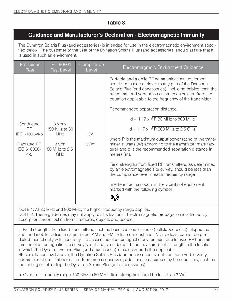
eleCTroMagneTIC eMIssIons and IMMunITy
DYNATRON SOLARIS® PLUS SERIES | SERVICE MANUAL REV. 6 | AUGUST 29, 2017 144
Table 3
Guidance and Manufacturer’s Declaration - Electromagnetic Immunity
The dynatron solaris Plus (and accessories) is intended for use in the electromagnetic environment speci-fied below. The customer or the user of the Dynatron Solaris Plus (and accessories) should assure that it is used in such an environment.
emissions Test
IeC 60601Test level
Compliance level electromagnetic environment guidance
Conducted rf
IeC 61000-4-6
radiated rfIeC 610000-
4-3
3 Vrms150 Khz to 80
Mhz
3 V/m80 Mhz to 2.5
ghz
3V
3V/m
Portable and mobile rf communications equipment should be used no closer to any part of the dynatron solaris Plus (and accessories), including cables, than the recommended separation distance calculated from the equation applicable to the frequency of the transmitter.
recommended separation distance
d = 1.17 x P 80 Mhz to 800 Mhz
d = 1.17 x P 800 Mhz to 2.5 ghz
where P is the maximum output power rating of the trans-mitter in watts (W) according to the transmitter manufac-turer and d is the recommended separation distance in meters (m).
Field strengths from fixed RF transmitters, as determined by an electromagnetic site survey, should be less than the compliance level in each frequency range
Interference may occur in the vicinity of equipment marked with the following symbol:
noTe 1: at 80 Mhz and 800 Mhz, the higher frequency range applies.noTe 2: These guidelines may not apply to all situations. electromagnetic propagation is affected by absorption and reflection from structures, objects and people.
a. Field strengths from fixed transmitters, such as base stations for radio (cellular/cordless) telephones and land mobile radios, amateur radio, aM and fM radio broadcast and TV broadcast cannot be pre-dicted theoretically with accuracy. To assess the electromagnetic environment due to fixed RF transmit-ters, an electromagnetic site survey should be considered. If the measured field strength in the location in which the dynatron solaris Plus (and accessories) is used exceeds the applicablerf compliance level above, the dynatron solaris Plus (and accessories) should be observed to verify normal operation. If abnormal performance is observed, additional measures may be necessary, such as reorienting or relocating the dynatron solaris Plus (and accessories).
b. Over the frequency range 150 KHz to 80 MHz, field strengths should be less than 3 V/m.

eleCTroMagneTIC eMIssIons and IMMunITy
DYNATRON SOLARIS® PLUS SERIES | SERVICE MANUAL REV. 6 | AUGUST 29, 2017 145
Table 4
Recommended separation distance between portable and mobile RF communications equipment and the Dynatron Solaris Plus (and accessories)The dynatron solaris Plus (and accessories) is intended for use in an electromagnetic environment in which radiated rf disturbances are controlled. The customer or the user of the dynatron solaris Plus (and accessories) can help prevent electromagnetic interference by maintaining a minimum distance between portable and mobile rf communications equipment (transmitters) and the dynatron solaris Plus (and accessories) as recommended below, according to the maximum power of the communications equipment.
separation distance (meters) according to frequency of transmitter
rated maximum output power of transmitter
W
150 khz to 80 Mhz
d = 1.17 x P
80 Mhz to 800 Mhz
d = 1.17 x P
800 Mhz to 2.5 ghz
d = 2.33 x P
0.01 0.12 0.12 0.23
0.1 0.37 0.37 0.74
1 1.2 1.2 2.3
10 3.7 3.7 7.4
100 12 12 23
for transmitters at a maximum output power listed above, the recommended separation distance (d) in meters (m) can be estimated using the equation applicable to the frequency of the transmitter, where P is the maximum output power rating of the transmitter in watts (W) according to the transmitter manufac-turer.
noTe 1: at 80 Mhz and 800 Mhz, the separation distance for the higher frequency range applies.
noTe 2: These guidelines may not apply to all situations. electromagnetic propagation is affected by absorption and reflection from structures, objects and people.

fInal qualITy CheCK (qC) CheCKoff sheeT
DYNATRON SOLARIS® PLUS SERIES | SERVICE MANUAL REV. 6 | AUGUST 29, 2017 146
Final Quality Check (QC) Checkoff Sheet
See the following pages for the graphical representations:

fInal qualITy CheCK (qC) CheCKoff sheeT
DYNATRON SOLARIS® PLUS SERIES | SERVICE MANUAL REV. 6 | AUGUST 29, 2017 147
Device Specific Procedure
QC, Assembly, Calibration, and Test D719 Check Sheet -1 of 9- DS0408A – REV 1
REVISION HISTORY REV. CO DESCRIPTION APPROVED DATE
0 12-0726 INITIAL RELEASE I. BROWN 2012-08-07 1 13-0402 UPDATED MICROCURRENT, 3WL QC CHANGES AND GENERAL UPDATE
DYNATRON SOLARIS PLUS D719 FINAL QUALITY CHECK (QC) CHECKOFF SHEET
Repair____RS____Production____ Software Version__________ (initials or mark) Refer to Test equipment operation manual and unit operating instructions/ manuals REPAIR/RS PROD
1 • Verify all keys function, all keys have feedback • Verify output turns off when STOP is pressed • Verify output will time out
2
INTERFERENTIAL: 42-55 Vpp (500ohm 10W load intensity 30) a) Static- High/Low (all channels) ± 4 Vpp
b) Target/ Sweep (all channels) c) Modify Features (mode, time, function, cancel) d) Verify current limit 50mA maximum with open load e) Verify conductance
3
PREMODULATED 42-55 Vpp (500ohm 10W load intensity 30) a) High/Low (all channels) b) High/Low alternating (all channels)
c) Modify Features (mode, time, cancel) d) Verify current limit 50mA maximum with open load e) Verify conductance
4
RUSSIAN STIM: 42-55 Vpp (500ohm 10W load intensity 30) a) One Channel Normal (all channels) b) Two Channel Reciprocal (channel pairs)
c) Two Channel Co-contraction (channel pairs)
5
BI-PHASIC: 42-55 Vpp (500ohm 10W load intensity 30) a) One Channel Normal (all channels) b) Two Channel Reciprocal (channel pairs)
c) Two Channel Co-contraction (channel pairs)
6
MICROCURRENT PADS: a) Verify no load, Freq .3Hz, turn off conductance; select Conductance and then
select OFF. At 50 uA +/-4% and at 990 uA +/-1% b) Verify the polarity changes. c) Verify conductance.
7 HIGH VOLT PADS:
a) No load, set device to 50 V, verify 42-52 V output. b) Verify that polarity changes.
8
MULTI-STIM PROBE: a) No load, Verify DC output, change Pulse Duration to 500. 0-20 mA b) Verify DC polarity change
c) Verify Hi-Volt output d) Verify Hi-Volt polarity change
e) Verify micro-current output f) Verify micro-current polarity change g) Verify micro-current audible tone h) Verify UP/DOWN key works i) Verify ON/OFF key works j) Verify conductance
Serial Number

fInal qualITy CheCK (qC) CheCKoff sheeT
DYNATRON SOLARIS® PLUS SERIES | SERVICE MANUAL REV. 6 | AUGUST 29, 2017 148
Device Specific Procedure
QC, Assembly, Calibration, and Test D719 Check Sheet -2 of 9- DS0408A – REV 1
Refer to Test equipment operation manual and unit operating instructions/ manuals REPAIR/RS PROD
9
TRI-WAVE LIGHT MEZZANINE OUTPUT: a) Verify treatment selections work b) Verify light pad operation c) Verify light probe operation
Refer to Table for probe and pad treatment times
Wave length Combination
DCP3 6 Joules
DLP3 10 Joules
IR / Red / Blue 1:00 min 8:42 min
10 Labels:
a) Apply Serial Number Label
Earth/Enclosure/Patient Leakages(Enclosure/Patient: tester clip to surface of enclosure or Patient lead ) NORMAL (no fault condition + neutral switch closed) Earth Leakage: Normal/Reversed Polarity, Earth switch depressed (<500 uA) / Enclosure Leakage: Normal/Reversed Polarity, Chassis switch depressed(<100uA) / Patient Leakage: Normal/Reversed Polarity, Chassis switch depressed(<100uA) / SINGLE FAULT (fault condition/ neutral switch open) Earth Leakage: Normal/Reversed Polarity, Earth switch depressed(<1000uA) / Enclosure Leakage: Normal/Reversed Polarity, Chassis switch depressed(<500uA) / Patient Leakage: Normal/Reversed Polarity, Chassis switch depressed(<500uA) /
ACCEPTANCE: Initials: Date: Technician
QC Inspector

fInal qualITy CheCK (qC) CheCKoff sheeT
DYNATRON SOLARIS® PLUS SERIES | SERVICE MANUAL REV. 6 | AUGUST 29, 2017 149
Device Specific Procedure
QC, Assembly, Calibration, and Test D719 Check Sheet -3 of 9- DS0408A – REV 1
DYNATRON SOLARIS PLUS ULTRASOUND
FINAL QUALITY CHECK (QC)CHECK SHEET Head SN: 5cm______________________10cm______________________2cm_______________________ (initials or mark)
Refer to Test equipment operation manual and unit operating instructions/ manuals REPAIR/RS PROD 1 Verify head temp.
2 Verify coupling.
3 Verify soundhead serial number
4 Combo with stim: Verify stim output through soundhead, using combo cable
5 Verify ultrasound output power
5cm 2.5 Watts (0.5) 5 Watts (1.0) 10 Watts (2.0) 1,2,3 MHz 2.4 – 2.6 4.9 – 5.1 9.8 – 10.2 10cm 5 Watts (0.5) 10 Watts (1.0) 20 Watts (2.0) 1,2 MHz 4.9 – 5.1 9.8 – 10.2 18.0 – 20.4 3 MHz 4.9 – 5.1 9.8 – 10.2 2cm 1 Watt (0.5) 2 Watts (1.0) 4 Watts (2.0) 1,2,3 MHz 0.9 – 1.1 1.9 – 2.1 3.5 – 4.1
Repair/RS: Record Parameters Before Calibration 2cm 1 mHz 2 mHz 3 mHz 5cm 1 mHz 2 mHz 3 mHz 10cm 1 mHz 2 mHz 3 mHz Freq Freq Freq Imped Imped Imped
Production & Repair/RS: Parameters Durring Calibration
2cm 1 mHz 2 mHz 3 mHz 5cm 1 mHz 2 mHz 3 mHz 10cm 1 mHz 2 mHz 3 mHz Freq Freq Freq Imped Imped Imped Volts Volts Volts
Repair/RS: Output as Recieved Calibrated Output
5cm 2.5W (0.5) 5Watts (1.0) 10W (2.0) 5cm 2.5W (0.5) 5Watts (1.0) 10W (2.0) 1 MHz 1 MHz 2 MHz 2 MHz 3 MHz 3 MHz
10cm 5W (0.5) 10Watts (1.0) 20W (2.0) 10cm 5W (0.5) 10Watts (1.0) 20W (2.0) 1 MHz 1 MHz 2 MHz 2 MHz 3 MHz 3 MHz
2cm 1W (0.5) 2W (1.0) 4W (2.0) 2cm 1W (0.5) 2W (1.0) 4W (2.0) 1 MHz 1 MHz 2 MHz 2 MHz 3 MHz 3 MHz
ACCEPTANCE: Initials:
Date:

dynaTron solarIs® Plus lIMITed WarranTy
DYNATRON SOLARIS® PLUS SERIES | SERVICE MANUAL REV. 6 | AUGUST 29, 2017 150
Dynatron Solaris® Plus Limited WarrantyDYNATRONICS CORPORATION warrants the Dynatron Solaris Plus 705, 706, 707, 708, and 709 products and the applicator soundheads, Peltier ThermoStim Probe, Tri-wave Light Probe, and Tri-Wave Light Pad (excluding other accessories) that are purchased with the unit to be free from factory defects in materials and workmanship under normal use for TWO YEARS from the date of purchase by the original owner. Accessories that accompany this product (which are listed as “accessories” on a list included with each unit) are warranted for 90 DAYS. If this product is defective within the warranty period, DYNATRONICS will, subject to the conditions set forth below:
(1) repair or replace defective parts at no charge within a reasonable period of time with new or remanufactured parts, at DYNATRONICS’ option; and
(2) provide labor for the repair or replacement of defective parts under this warranty without charge.
Parts used for replacement under this warranty are warranted for the remainder of the original warranty period. THE REPAIR OR REPLACEMENT OF DEFECTIVE PARTS SHALL CONSTITUTE THE SOLE AND EXCLUSIVE REMEDY IN THE EVENT OF A BREACH OF WARRANTY.
REGISTRATION REQUIRED. In order for this warranty to be valid, the warranty registration card (included with the product) must be filled out and returned to DYNATRONICS within 30 days of purchase by the original owner. A copy of an invoice or receipt may be requested to verify purchase date.
REPAIRS. All repairs must be performed by an authorized service facility. Any modifications or repairs by unauthorized parties will void this warranty.
OBTAINING WARRANTY SERVICE. Authorization by DYNATRONICS is required before obtaining service under this warranty. Therefore, before shipping or delivering this product to an authorized service facility for warranty service, call DYNATRONICS and obtain a return authorization number.
PACKAGING AND SHIPPING. Any unit shipped to an authorized service facility for service under this warranty must be in the original shipping carton, freight prepaid, fully insured, and properly packed to prevent damage. DYNATRONICS is not liable for any damage to the unit while in transit. Include a summary of the problem with the product. Write the return authorization number obtained from DYNATRONICS on the shipping label.
SHIPPING COSTS. Within the first 30 days of the warranty period, DYNATRONICS will pay all necessary shipping costs associated with obtaining service under this warranty. After the first 30 days of the warranty period, the owner is responsible for all costs associated with shipping the product to an authorized service facility. DYNATRONICS will pay all costs associated with shipping the product back to the owner after service is completed, and will ship the product using the same carrier or type of carrier and service that was used by the owner for the incoming shipment.
EXCLUSIONS. Any defect, malfunction or failure caused by or resulting from improper installation, service, maintenance or repair, or from abuse, neglect, transportation, accident, act of God, or other cause beyond the control of DYNATRONICS will not be covered by this limited warranty. ANY IMPLIED WARRANTIES COVERING THIS PRODUCT, INCLUDING BUT NOT LIMITED TO WARRANTIES OF MERCHANTABILITY OR FITNESS FOR A PARTICULAR PURPOSE, ARE LIMITED IN DURATION TO ONE YEAR FROM THE DATE OF PURCHASE BY THE ORIGINAL OWNER. DYNATRONICS SHALL NOT IN ANY CASE BE LIABLE FOR SPECIAL, INCIDENTAL, CONSEQUENTIAL, INDIRECT, OR OTHER SIMILAR DAMAGES ARISING FROM BREACH OF WARRANTY, BREACH OF CONTRACT, NEGLIGENCE, OR ANY OTHER LEGAL THEORY EVEN IF DYNATRONICS HAS BEEN ADVISED OF THE POSSIBILITY OF SUCH DAMAGES. SOME STATES DO NOT ALLOW LIMITATIONS ON HOW LONG AN IMPLIED WARRANTY LASTS OR THE EXCLUSION OR LIMITATION OF INCIDENTAL OR CONSEQUENTIAL DAMAGES, SO THE ABOVE LIMITATION OR EXCLUSION MAY NOT APPLY TO YOU. THIS WARRANTY GIVES YOU SPECIFIC LEGAL RIGHTS, AND YOU MAY ALSO HAVE OTHER RIGHTS WHICH VARY FROM STATE TO STATE.
For more information concerning repairs, operation, or technical assistance, please contact the DYNATRONICS dealer nearest you, or contact DYNATRONICS directly at: the address below.
Dynatronics Corporation7030 Park Centre Drive • Salt Lake City, Utah 84121 • (801) 568-7000 (800) 874-6251