dynisco vertex™ melt hg free pressure sensors
TRANSCRIPT

P/N: 974155 | Rev: 030521 | ECO: 52129 www.dynisco.com
From lab to production, providing a window into the process
-1-
Hg free Intrinsically safe pressure sensors designed specifically for extrusion and
polymer processing applications
Operating Manual
Dynisco Vertex™ Melt Hg Free Pressure Sensors
P/N: 974155 | Rev: 030521 | ECO: 52129 www.dynisco.com
From lab to production, providing a window into the process
-2-
DYNISCO VERTEX QUICK START CARD This Quick Start Setup guide can be used by experienced instrumentation technicians to configure the sensor using the Zero and Span actuators or via the optional HART communications. For more detailed information, please consult the complete manual before operating. The Quick Start procedure is intended for users already familiar with the use of Melt Pressure Sensors and Instrumentation.
1. Insure the process connection is clean and clear of any debris and is machined to the proper dimensions. Machine tool kits with port gages are available (see sections 6 & 12 of manual)
2. Apply anti‐seize as appropriate then install the sensor into the process connection.
(Do NOT torque sensor into the hole at this time!)
3. Allow time for the sensor temperature to equalize to the process temperature. This will
help eliminate thread galling and ease removal later. There should be NO pressure applied at this time.
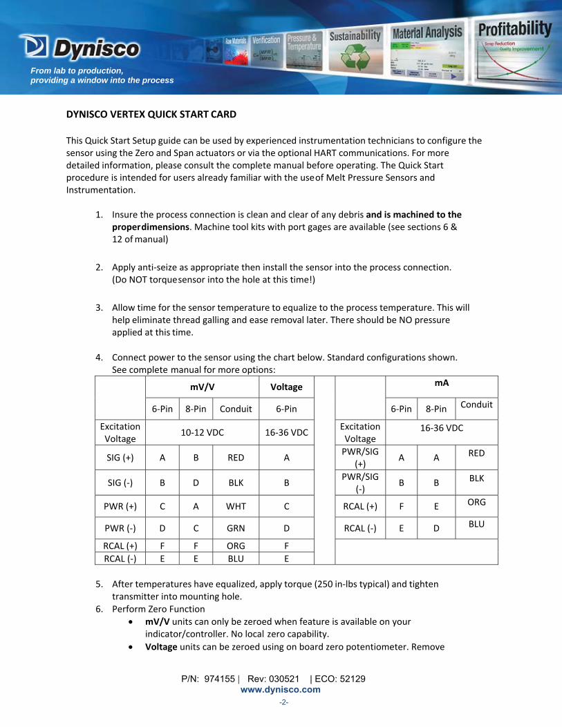
4. Connect power to the sensor using the chart below. Standard configurations shown.
See complete manual for more options:
mV/V Voltage mA
6‐Pin 8‐Pin Conduit 6‐Pin 6‐Pin 8‐Pin Conduit
Excitation Voltage
10‐12 VDC 16‐36 VDC Excitation Voltage
16‐36 VDC
SIG (+) A B RED A PWR/SIG
(+) A A RED
SIG (‐) B D BLK B PWR/SIG
(‐) B B BLK
PWR (+) C A WHT C RCAL (+) F E ORG
PWR (‐) D C GRN D RCAL (‐) E D BLU
RCAL (+) F F ORG F RCAL (‐) E E BLU E
5. After temperatures have equalized, apply torque (250 in‐lbs typical) and tighten transmitter into mounting hole.
6. Perform Zero Function
mV/V units can only be zeroed when feature is available on your indicator/controller. No local zero capability.
Voltage units can be zeroed using on board zero potentiometer. Remove
P/N: 974155 | Rev: 030521 | ECO: 52129 www.dynisco.com
From lab to production, providing a window into the process
-3-
seal screw and adjust potentiometer until desired output is achieved. Replace seal screw when complete.
mA units have a variety of on board Zero Adjustments types (based on configuration), i.e. potentiometer, pushbuttons, and HALL Effect Switches.
o For units with potentiometers, remove seal screw and adjust potentiometer until desired output is achieved. Replace seal screw when complete.
o For units with pushbuttons, remove seal screw, using a 2mm or smaller Allen Key, depress pushbutton for ½ sec, release pushbutton for ½ sec, depress pushbutton for ½ sec and release. Replace seal screw when complete.
o For units with HALL Effect Switches, unthread zero screw from endplate, depress screw, release screw, depress screw, release screw and return screw in endplate (failure to return the screw on units with HALL Effects Switches will cause the unit to go into failsafe).
DYNISCO VERTEX QUICK START SETUP GUIDE UTILIZING HART COMMUNICATOR
This section only applies to mA HART units.
1. Follow steps 1 through 5 from DYNISCO VERTEX QUICK START SETUP GUIDE. 2. Connect HART Handheld to the loop. 3. Power on the HART Handheld. See HART Command tree on the following page for
reference. 4. From the Main Menu:
a. Enter Tag (Quick Key 1, 3, 1). b. Set pressure units (Quick Key 1, 3, 2), if required. c. Set URV (Quick Key 1, 3, 3, 2) if output turndown (rescaling), is required. d. Perform Zero Trim (Quick Key 1, 2, 5, 1, 3, 1)
5. Verify loop output is zero (4mA). 6. Remove HART Handheld from the loop.
P/N: 974155 | Rev: 030521 | ECO: 52129 www.dynisco.com
From lab to production, providing a window into the process
-4-
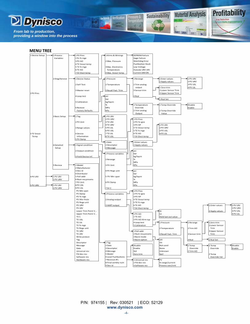
MENU TREE
1 Device Setup 1 Process
Variables
1 PV Pres 2 Pv % rnge
3 PV AO
4 TV Snout temp
5 TV % rnge
6 TV AO
7 SV Elect temp
1Alrms &Wrnings
2 Max. Pressure
3 Max. Electronics
Temperature
4 Max. Snout Temp
EEPROMFailure
Gage Failure
Watchdog Error
Pushbutton Stuck
Low Voltage
Outside URV LRV
Current SIM ON
2 Diag/Service 1 Device Status 1 Pressure 1 Rerange 1 Enter values
2 Apply values
2 Self Test 2 Temperature
3 Master reset 3 Recall Fact. Trim
2 Trim analog
output
3 Sensor trim
1 PV LRV 2 PV URV
3 PV USL
4 PV LSL
2 PV Pres
1 Zero trim
2 Lower Sensor Trim
3 Upper Sensor Trim
4 Loop test
5 Calibration
6 Restore
Factory Defaults
psi
bar
kg/Sqcm
%
MPa
KPa
4 Rcal
1 Rcal Set
1 Temperature
Override
2 Trim analog
Output
1 Temp Override Disable
Enable
2 Temp Override
Value
3 Basic Setup 1 Tag
2 PV Unit
3 Range values
3 TV Snout
Temp
4 Device
Information
5 PV Damp
1 PV LRV
2 PV URV
3 TV LRV
4 TV URV
5 PV LSL
6 PV USL
7 TV LSL
8 TV USL
1 PV Pres
2 PV % rgne
3 PV AP
4 TV Snout temp
5 TV % rnge
6 TV AO
7 SV Elect temp
1 PV LRV
2 PV URV
3 PV USL
4 PV LSL
4 Detailed
Setup
1 Signal condition
1 Date
2 Descriptor
3 Message
1 Enter values
2 Apply values
2 Output condition
1 Process variables
3 Field Device Inf.
2 Rerange
5 Review
psi
bar
kg/Sqcm
%
MPa
KPa
4 PV LRV 1 PV LRV 2 PV URV
1 Model
2 Manufacturer
3 Dev id
4 Distributor
5 Poll addr
6 Num req preams
7 PV Unit
8 PV USL
9 PV LSL
PV Min span
PV Damp
PV % rnge
PV Xfer fnctn
PV Rnge unit
PV URV
PV LRV
Lower Trim Point V…
Upper Trim Point V…
TV C
TV USL
TV LSL
TV % rnge
TV Rnge unit
TV URV
TV LRV
Write protect
Tag
Descriptor
Message
Date
Universal rev
Fld dev rev
Software rev
Hardware rev
3 PV Unit
4 PV Rnge unit
5 PV Min span
6 PV Damp
5 PV URV 1 PV LRV 2 PV URV
psi
bar
kg/Sqcm
%
MPa
KPa
7 SV C
1 Process variables
2 Analog output
3 HART output
1 PV Pres
2 PV % rgne
3 PV AP
4 TV Snout temp
5 TV % rnge
6 TV AO
7 SV Elect temp
1 Enter values
1 PV AO
2 TV AO
3 PV AO Alrm typ
4 Loop test
5 Calibration
Hi
Lo
Hold last out value
2 Apply values
1 PV LRV
2 PV URV
3 PV USL
4 PV LSL
1 Pressure 1 Rerange
2 Temperature 2 Trim AO
1 Poll addr
2 Num req preams
3 Burst mode
4 Burst option
3 Recall Fact. Trim 3 Sensor trim
1Zero trim
2 Lower Sensor
Trim
3 Upper Sensor
Trim
1 Tag
2 Date
3 Descriptor
4 Message
5 Model
6 Local Pushbuttons
7 Revision #'s
8 Final asmbly num
9 Dev id
Disable
Enable
Std
Zero trim
Off
On
Not used
None
Unknown
Spcl
4 Rcal 1 Rcal Set
1 Temp
Override
2 Trim AO
1 Temp
Override
Disable
Enable
2 Temp
Override Val
1 Universal rev
2 Fld dev rev
3 Software rev
PV
% range/current
Process vars/crnt
P/N: 974155 | Rev: 030521 | ECO: 52129 www.dynisco.com
From lab to production, providing a window into the process
-5-
TABLE OF CONTENTS
1 VERTEX CARE AND HANDLING ............................................................................................................................................. 6
2 GENERAL .............................................................................................................................................................................. 7
3 NOTES ON SAFETY .............................................................................................................................................................. 11
4 TECHNICAL DATA ............................................................................................................................................................... 18
5 TRANSPORT/DELIVERY/STORAGE ...................................................................................................................................... 23
6 INSTALLATION AND REMOVAL ........................................................................................................................................... 24
7 COMMISSIONING ............................................................................................................................................................... 32
8 UTILIZING THE HART COMMUNICATIONS.......................................................................................................................... 35
9 MAINTENANCE ................................................................................................................................................................... 47
10 TROUBLESHOOTING ........................................................................................................................................................... 49
11 DYNISCO CONTACT INFORMATION.................................................................................................................................... 50
12 ACCESSORIES ...................................................................................................................................................................... 51
13 APPROVALS/CERTIFICATES ................................................................................................................................................. 55
14 OUTLINE DRAWINGS .......................................................................................................................................................... 58
P/N: 974155 | Rev: 030521 | ECO: 52129 www.dynisco.com
From lab to production, providing a window into the process
-6-
1 VERTEXCAREANDHANDLING
Be sure that the port where the Vertex transducer will be installed is free of all residual dried polymer
from previous manufacturing processes (This is accomplished using Dynisco's machine whole tooling
kit part number 200100).
In applications where the Vertex transducer will be removed in between production runs, such as in
the manufacture of food products or medical tubing, only remove the Vertex when the polymer is at,
or near, full process temperature. This will insure that you are pulling the transducer tip from molten
conditions and therefore not causing any undue pulling effect on the diaphragm that could result in
damage to the tip and a transducer that is then out of specification.
If there is residual polymer material on the tip when the sensor is removed from a process port,
NEVER use a wire brush, wire wheel, blunt or sharp instrument to remove the polymer. There
are two acceptable ways of removing residual material from the tip of any pressure sensor:
After removing the Vertex sensor, carefully clean the diaphragm with a soft cloth or bronze wool
while the medium is still malleable. Do not attempt to clean the sensor by heating solidified polymer
with a torch.
A solvent bath consisting of glycol can be used to soften the polymer and improve removal. Place the
tip of the sensor into the solvent bath for a period of time as determined by when the residual
polymer softens. Be careful to not immerse the electronics in the bath. This bath can be heated using
heat elements to increase removal effectiveness and shorten cycle time. Then follow procedure “a.”
above.
When installing the Vertex sensor, it is important not to over‐torque the unit into place. The unit
should be hand tightened, and then tightened to the installation torque specified in section 4.4 with a
torque wrench.
Adjust zero after installing and heating the machine to operating temperature. Where filled
sensors are sensitive to vertical orientation changes, Vertex is sensitive to horizontal orientation
changes and installation torque. Reduce zero‐shift impact by setting zero and span after properly
installing the sensor in the process port.
Do not adjust the Span potentiometer with Rcal activated. Span potentiometer adjustments should
only be made with the unit installed into a calibrated pressure source at FS pressure.
P/N: 974155 | Rev: 030521 | ECO: 52129 www.dynisco.com
From lab to production, providing a window into the process
-7-
2 GENERAL
2.1 IMPORTANT INFORMATION .......................................................................................................................................... 7
2.2 COPYRIGHT ............................................................................................................................................................ 7
2.3 EXPLANATION OF ICONS ................................................................................................................................................ 8
2.4 ABBREVIATIONS ............................................................................................................................................................ 9
2.5 NAMING CONVENTION .................................................................................................................................................. 9
2.6 TRANSMITTER PRINCIPLES OF OPERATION ................................................................................................................... 9
2.7 CORRECT USE .......................................................................................................................................................... 10
2.8 USER’S OBLIGATIONS ................................................................................................................................................... 10
2.1 IMPORTANTINFORMATION This manual applies to the Vertex brand sensor product family only. This manual must be kept near the equipment in a readily and immediately accessible location at all times. The content of this manual must be read, understood and followed in its entirety. This applies in particular to the notes on safety. Following the safety instructions will help to prevent accidents, defects and malfunctions.
Dynisco will not be held liable for any injury, loss or damage resulting from failure to follow the instructions in this manual.
If the product malfunctions, in spite of having followed the operating instructions, please contact
customer service from our website: www.dynisco.com/contact
2.2 COPYRIGHT Copyright law requires that this manual be used for intended purposes only. It is strictly forbidden to allow reproduction of any kind “in whole or in part” to persons outside of Dynisco, without approval from Dynisco. HART is a registered trademark of HART Communication Foundation.
P/N: 974155 | Rev: 030521 | ECO: 52129 www.dynisco.com
From lab to production, providing a window into the process
-8-
ATTENTION
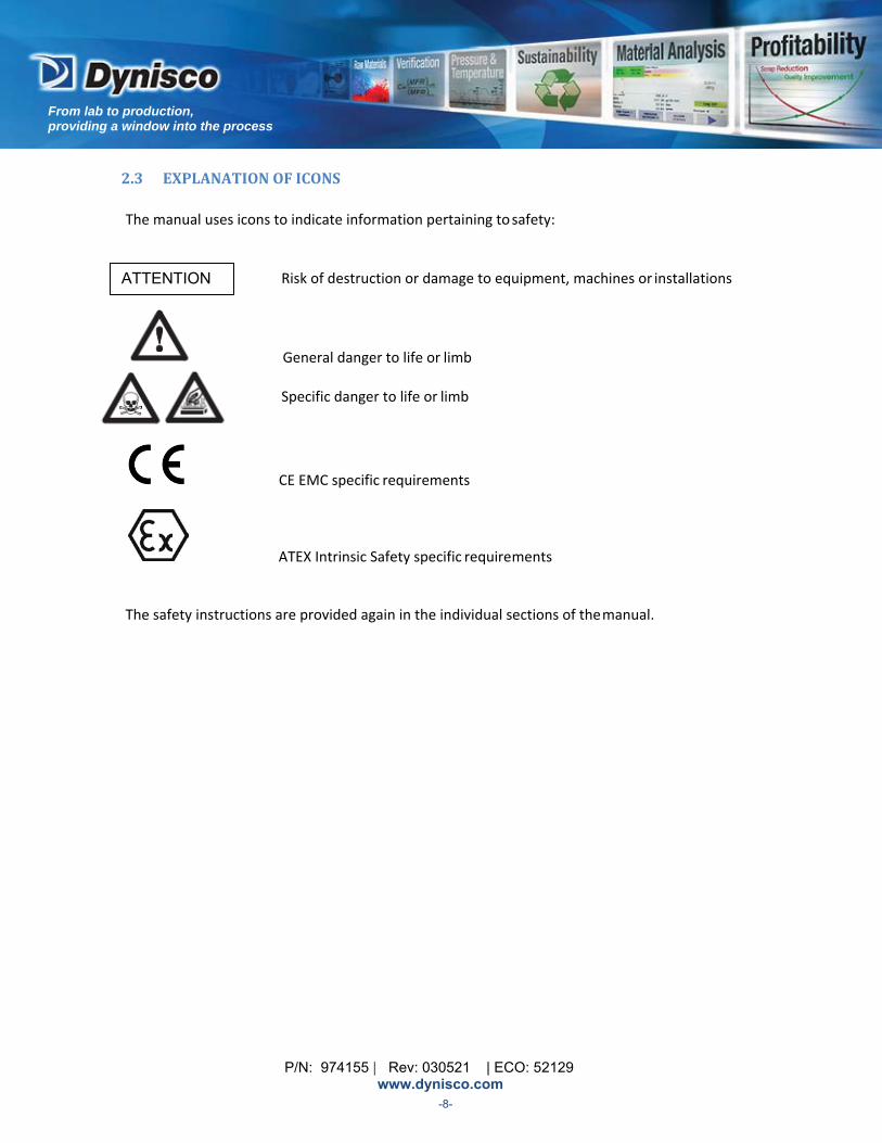
2.3 EXPLANATIONOFICONS
The manual uses icons to indicate information pertaining to safety:
Risk of destruction or damage to equipment, machines or installations
General danger to life or limb
Specific danger to life or limb
CE EMC specific requirements
ATEX Intrinsic Safety specific requirements
The safety instructions are provided again in the individual sections of the manual.
P/N: 974155 | Rev: 030521 | ECO: 52129 www.dynisco.com
From lab to production, providing a window into the process
-9-
2.4 ABBREVIATIONS
The following abbreviations are used: EMC Electromagnetic Compatibility ESD Electrostatic discharge Exc Excitation mA milliampere mV/V millivolt per volt (a standard pressure sensor output) Pwr Power Sig Signal T/C Thermocouple in‐lbs inch Pounds (torque) BSL Best Straight Line DD Device Descriptor EEPROM Electrically Erasable Programmable Read Only Memory FS Full Scale HART Highway Addressable Remote Transducer LRV Lower Range Value PT Pressure Transmitter PV Primary Variable (Pressure) RTD Resistance Temperature Detector (A very accurate temperature sensor) SV Secondary Variable (Electronics Temperature) TV Tertiary Variable (Snout Temperature) URV Upper Range Value Watchdog An internal monitor for the electronics
2.5 NAMINGCONVENTION Vertex Vertex Brand Pressure Sensor
2.6 TRANSMITTERPRINCIPLESOFOPERATION
The mechanical system consists of a diaphragm located on the sensor tip. The diaphragm is a metal plate designed to deflect in response to pressure applied to the tip. The diaphragm is in direct contact with the fluid media (gas or liquid) to be measured and its purpose is to convert the pressure of the media to mechanical deflection.
Inside the sensor, the diaphragm plate deflection is converted to a mV electrical signal. Electronic circuitry performs the signal conditioning necessary to convert that signal into the output (mV/V or 4‐20mA or voltage).
An optional J or K‐thermocouple process temperature output is also available. These outputs are from a customer accessible thermocouple included in the snout tip.
P/N: 974155 | Rev: 030521 | ECO: 52129 www.dynisco.com
From lab to production, providing a window into the process
-10-
An optional shunt calibration (Rcal) output is also available. Rcal is a method of generating an electrical output to match the electrical output that would be given in response to an applied pressure. Rcal is normally set to 80%FS so that all similar sensors calibrate at the same point to facilitate interchangeability. Rcal traces its routes to strain gage transducers. In strain gage technology, Rcal is normally a resistor inserted into the Wheatstone bridge to offset its output as if 80% pressure was applied. In the Vertex brand sensor, Rcal is an electrical simulation of 80% pressure and is created in the electronics circuitry. Do not adjust the Span potentiometer with Rcal activated. Span potentiometer adjustments should only be made with the unit installed into a calibrated pressure source at FS pressure.
2.7 CORRECTUSE
When using a Vertex brand sensor as a safety component in accordance with the EC Machine Directive, Annex IIc, the equipment manufacturer must take any necessary precautions to ensure that malfunction of the PT cannot cause damage or injury.
For installation in explosive gas atmospheres the device must be installed in accordance with European installation guidelines EN 60079‐14. For category 1 (zone 0) installations, over voltage protection of the electrical connections shall be in accordance to EN 60079‐14. When planning machinery and using one of the sensors from the Vertex brand sensor Family, follow the safety and accident prevention regulations that apply to your application, such as:
EN 60204, Electrical equipment in machines
EN 12100, Machine safety, general design guidelines
DIN 57 100 Part 410, Protection against electric shock
EN 60079‐0 Explosive atmospheres ‐ General Requirements
EN 60079‐11 Explosive atmospheres ‐ Intrinsically Safe Apparatus
EN 60079‐26 Special Requirements for EPL Ga
2.8 USER’SOBLIGATIONS
The operator or owner of the larger overall system, e.g. a machine, is responsible for following the safety and accident prevention regulations that apply to the specific application.
P/N: 974155 | Rev: 030521 | ECO: 52129 www.dynisco.com
From lab to production, providing a window into the process
-11-
3 NOTESONSAFETY
3.1 RISK OF DESTRUCTION OR DAMAGE TO EQUIPMENT, MACHINE, OR INSTALLATION ............................... 11
3.2 GENERAL DANGER TO LIFE OR LIMB .......................................................................................................... 11
3.3 CE EMC SPECIFIC REQUIREMENTS ............................................................................................................. 12
3.3.1 mV/V analog output ................................................................................................................................... 12
3.3.2 mA analog output ....................................................................................................................................... 12
3.3.3 Voltage analog output ................................................................................................................................ 12
3.4 ATEX INTRINSIC SAFETY APPROVAL SPECIFIC REQUIREMENTS .................................................................. 13
3.1 RISKOFDESTRUCTIONORDAMAGETOEQUIPMENT,MACHINE,ORINSTALLATION Avoid applying transverse loads to the rigid portion of the sensor protruding from the equipment/mounting port.
The Vertex brand sensor is an ESD sensitive component. Electrostatic discharge may damage the Vertex brand sensor. Take ESD precautions when contacting input/output pins or lead wires.
3.2 GENERALDANGERTOLIFEORLIMB The operator or owner of the larger overall system is responsible for following the safety and accident prevention regulations that apply to the specific application. Dynisco will not be held liable for any injury, loss or damage resulting from failure to follow the instructions in this manual. Electrical shock can result in death or serious injury. Avoid contact with the leads and terminals. High voltage that may be present on leads can cause electrical shock. Mounting and electrical connection of the PT must be done by specialists with EMC training, following all applicable regulations, and in pressure‐less, voltage‐free, intrinsically safe condition with the machine switched off. The machine must be secured against being switched back on! Deviation of the supply voltage from the value given in the technical specifications, or reverse polarity, can damage the pressure transmitter and cause malfunctions that can pose a risk of explosion.
Several configurations of Vertex are designed and approved for use in hazardous classified areas. Units intended for installation in these areas must bear the applicable approval agency label.
ATTENTION
P/N: 974155 | Rev: 030521 | ECO: 52129 www.dynisco.com
From lab to production, providing a window into the process
-12-
3.3 CEEMCSPECIFICREQUIREMENTS
The housing of the transmitter must be reliably connected to the local equipotential bonding system. The housing is electrically bonded to the process equipment through the process connection.
3.3.1 mV/Vanalogoutput All mV/V PTs need to have a shield connection to ground at the process connection and instrumentation ends.
All mV/V PTs with conduit fitting (electrical connection codes 6*C) have a connection between the conduit cable shield and the case internally at the conduit fitting.
For mV/V PTs with connector fitting, it is the customer’s responsibility to insure there is a connection between the connector cable shield and the mating connector.
3.3.2 mAanalogoutput All mA PTs need to have a shield connection to ground at the process connection end.
For ATEX IS approved mA PTs, only connect the case and/or shield leads to ground at the instrumentation end if a high level of assurance exists that there is potential equalization between each end of the circuit to avoid the danger of circulating fault currents.
All mA PTs with conduit fitting (electrical connection codes 3*C, 5*C) have connections between the conduit cable shield and case lead to the case internally at the conduit fitting.
For mA PTs with connector fitting, it is the customer’s responsibility to insure there is a connection between the connector cable shield and the mating connector.
3.3.3 Voltageanalogoutput All V PTs need to have a shield connection to ground at the process connection end. All V PTs with connector fitting, it is the customer’s responsibility to insure there is a connection between the connector cable shield and the mating connector.

P/N: 974155 | Rev: 030521 | ECO: 52129 www.dynisco.com
From lab to production, providing a window into the process
-13-
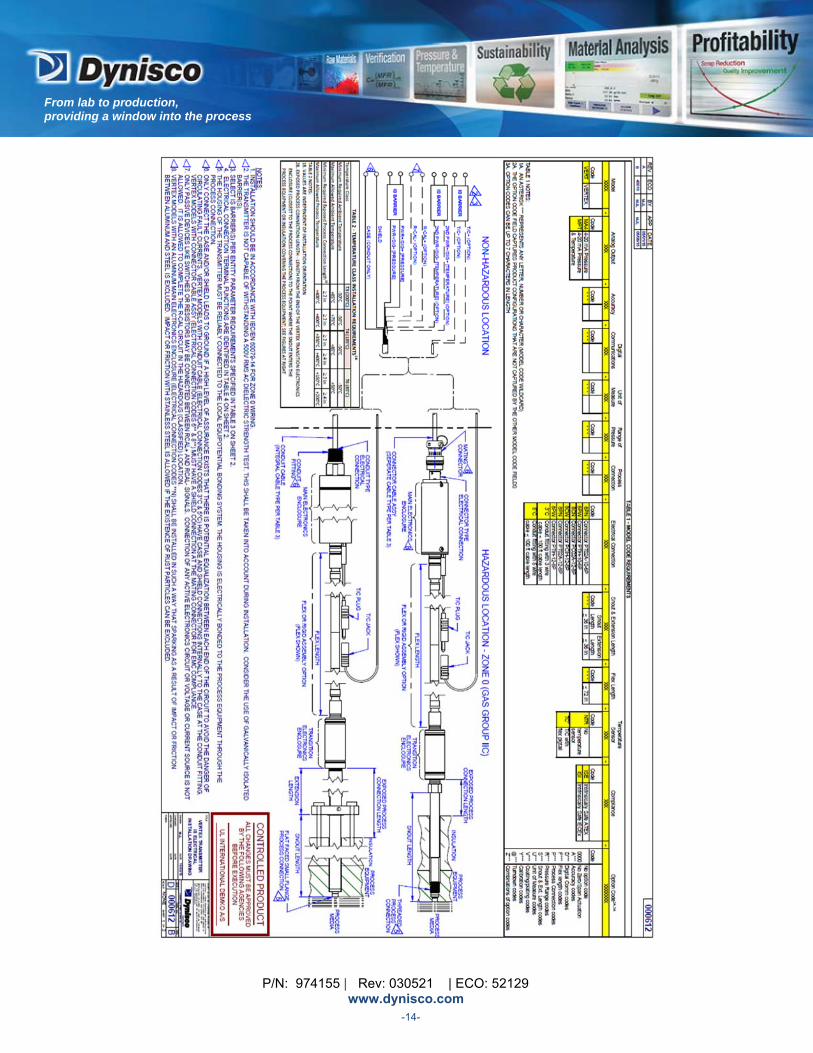
3.4 ATEXINTRINSICSAFETYAPPROVALSPECIFICREQUIREMENTS
This section only applies to PTs with ATEX IS option.
Equipment Marking Information Model Number: (Please review the calibration sheet that came with your PT shipment) Range: (Please review the calibration sheet that came with your PT shipment) Input: 24VDC Output: 4‐20mA Stem: (Please review the calibration sheet that came with your PT shipment) Flex: (Please review the calibration sheet that came with your PT shipment) ATEX Approval Markings:
Manufacturer Address: Dynisco Instruments www.dynisco.com Franklin, MA 02038
Instructions for safe putting into service & installation After installing the device, but before operating the device, the user must check that the complete installation and wiring is intrinsically safe. Special care must be taken to insure that the power supply is a certified apparatus. Also review control drawing 000612, which is included at the end of this section.
Instructions for safe use Review control drawing 000612, which is included at the end of this section.
Maintenance (servicing and emergency repair), assembly, dismantling and adjustment The PT does not require any instructions for safe maintenance, assembly, dismantling or adjustment
Safe electrical and pressure parameters and maximum surface temperature limits Maximum allowed PT pressure: (Please review the calibration sheet that came with your PT shipment) Also review control drawing 000612, which is included at the end of this section.
Special Conditions of use Review control drawing 000612, which is included at the end of this section.
P/N: 974155 | Rev: 030521 | ECO: 52129 www.dynisco.com
From lab to production, providing a window into the process
-14-
P/N: 974155 | Rev: 030521 | ECO: 52129 www.dynisco.com
From lab to production, providing a window into the process
-15-
P/N: 974155 | Rev: 030521 | ECO: 52129 www.dynisco.com
From lab to production, providing a window into the process
-16-
P/N: 974155 | Rev: 030521 | ECO: 52129 www.dynisco.com
From lab to production, providing a window into the process
-17-
P/N: 974155 | Rev: 030521 | ECO: 52129 www.dynisco.com
From lab to production, providing a window into the process
-18-

P/N: 974155 | Rev: 030521 | ECO: 52129 www.dynisco.com
From lab to production, providing a window into the process
-19-
4 TECHNICALDATA
4.1 MODEL CODE BREAKDOWN ............................................................................................ 20
4.2 PERFORMANCE CHARACTERISTICS ............................................................................... 20
4.2.1 ACCURACY ......................................................................................................................... 20
4.2.2 RESOLUTION ..................................................................................................................... 20
4.2.3 REPEATABILITY ................................................................................................................ 20
4.2.4 OVERLOAD PRESSURE (MAX PRESSURE WITHOUT INVALIDATING SPECIFIED ACCURACY) ........................................................................................................................ 20
4.2.5 BURST PRESSURE ............................................................................................................. 20
4.2.6 RESPONSE TIME ............................................................................................................... 20
4.3 ELECTRICAL DATA ........................................................................................................... 21
4.4 INSTALLATION SPECIFICATIONS .................................................................................... 21
4.5 TEMPERATURE SPECIFICATIONS ................................................................................... 21
4.6 INSTALLATION INFLUENCE ............................................................................................ 22
4.7 TEMPERATURE INFLUENCE ............................................................................................ 22
4.8 EMC REQUIREMENTS ....................................................................................................... 23
4.9 MATERIALS ....................................................................................................................... 23
4.10 ENVIRONMENTAL PROTECTION TO ANSI/IEC-60529 & ANSI/NEMA-250 ................ 23
4.11 WEIGHT ............................................................................................................................. 23
4.12 DIMENSIONS ..................................................................................................................... 23
P/N: 974155 | Rev: 030521 | ECO: 52129 www.dynisco.com
From lab to production, providing a window into the process
-20-
4.1 MODELCODEBREAKDOWN Please see Vertex datasheet on www.dynisco.com
4.2 PERFORMANCECHARACTERISTICS
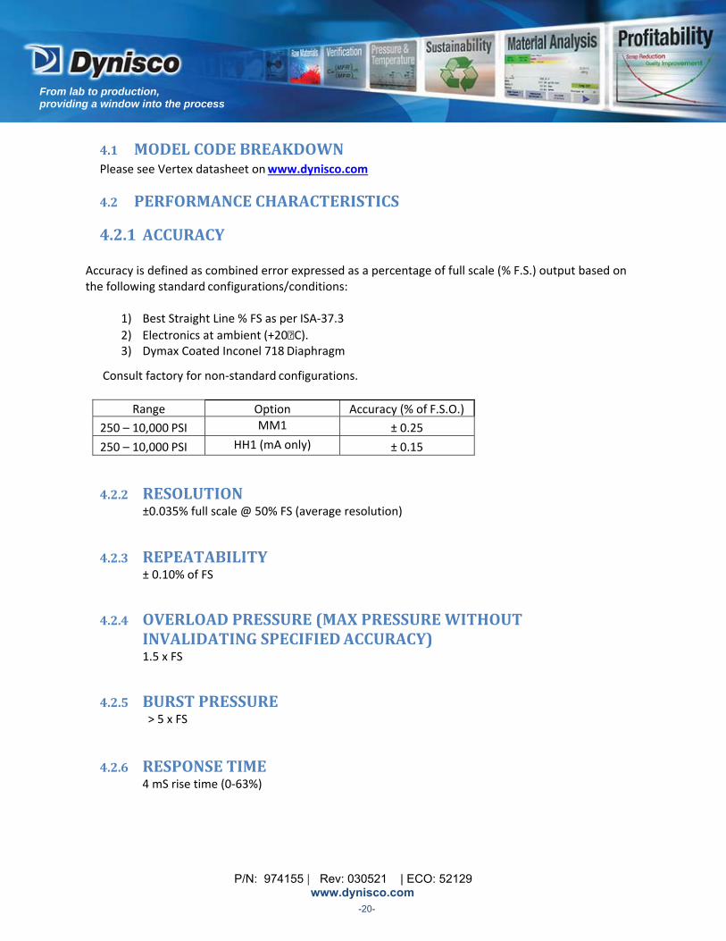
4.2.1ACCURACY Accuracy is defined as combined error expressed as a percentage of full scale (% F.S.) output based on the following standard configurations/conditions:
1) Best Straight Line % FS as per ISA‐37.3
2) Electronics at ambient (+20 C). 3) Dymax Coated Inconel 718 Diaphragm
Consult factory for non‐standard configurations.
Range Option Accuracy (% of F.S.O.)
250 – 10,000 PSI MM1 ± 0.25
250 – 10,000 PSI HH1 (mA only) ± 0.15
4.2.2 RESOLUTION ±0.035% full scale @ 50% FS (average resolution)
4.2.3 REPEATABILITY ± 0.10% of FS
4.2.4 OVERLOADPRESSURE(MAXPRESSUREWITHOUTINVALIDATINGSPECIFIEDACCURACY) 1.5 x FS
4.2.5 BURSTPRESSURE > 5 x FS
4.2.6 RESPONSETIME 4 mS rise time (0‐63%)
P/N: 974155 | Rev: 030521 | ECO: 52129 www.dynisco.com
From lab to production, providing a window into the process
-21-
4.3 ELECTRICALDATA Output Signal 2‐wire 4‐20 mA or mV/V or voltage mV/V Specifications 3.3 mV/V mA Specifications 4‐20 mA, endpoints set by zero/span actuators voltage Specifications 0‐5V, 0‐10V, 1‐6V, or 1‐11V set by zero/span actuators T/C Specifications +/‐ 2°C Current Consumption < 30 mA Supply Voltage 4‐20mA or voltage: 16‐36V (Note: sensor incorporates overvoltage
protection and reverse polarity protection and will not operate if inputs are reversed). mV/V: 10V recommended, 10‐12V
4.4 INSTALLATIONSPECIFICATIONS
Installation Torque 250 in‐lbs. recommended
300 in‐lbs max (Transducers installed at a mounting torque above this may damage unit and may be difficult to remove even when anti‐seize compound is applied).
Removal Torque Do not exceed 500 in‐lbs
Flex bend radius 1 inch (25 mm) minimum
4.5 TEMPERATURESPECIFICATIONS
Electronics Housing Operating Temperature Range ‐58 to +185°F (‐50 to +85°C) Compensated Temperature Range +68 to +150°F (+20 to +65°C)
Flex and Transition
Operating Temperature Range ‐58 to +300°F (‐50 to +150°C) Compensated Temperature Range +68 to +300°F (+20 to +150°C)
Rigid Snout
Operating Temperature Range ‐58 to +750°F (‐50 to +400°C) Compensated Temperature Range +68 to +660°F (+20 to +350°C)
P/N: 974155 | Rev: 030521 | ECO: 52129 www.dynisco.com
From lab to production, providing a window into the process
-22-
4.6 INSTALLATIONINFLUENCE
Installation Torque zero shift < 3% FS typical @ 250 in‐lb Rotational Zero shift ± 1.5% FS typical in horizontal orientation, insignificant in
vertical orientation
4.7 TEMPERATUREINFLUENCE
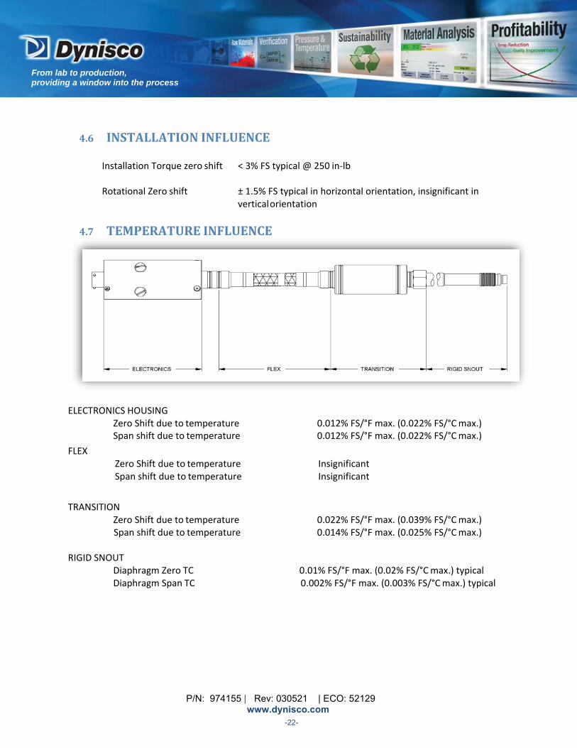
ELECTRONICS HOUSING
Zero Shift due to temperature 0.012% FS/°F max. (0.022% FS/°C max.) Span shift due to temperature 0.012% FS/°F max. (0.022% FS/°C max.)
FLEX Zero Shift due to temperature Insignificant Span shift due to temperature Insignificant
TRANSITION Zero Shift due to temperature 0.022% FS/°F max. (0.039% FS/°C max.)
Span shift due to temperature 0.014% FS/°F max. (0.025% FS/°C max.)
RIGID SNOUT Diaphragm Zero TC 0.01% FS/°F max. (0.02% FS/°C max.) typical Diaphragm Span TC 0.002% FS/°F max. (0.003% FS/°C max.) typical
P/N: 974155 | Rev: 030521 | ECO: 52129 www.dynisco.com
From lab to production, providing a window into the process
-23-
4.8 EMCREQUIREMENTS Please review EMC requirements section 3.3
4.9 MATERIALS
Standard Diaphragm Inconel 718 (Dymax coated)
Standard Wetted Parts 17‐4PH UNS Mat No. S17400
4.10 ENVIRONMENTALPROTECTIONTOANSI/IEC‐60529&ANSI/NEMA‐250
Ingress Protection = IP54 (IP67 if the unit is welded and the temperature sensor code is “NTR”).
Welded units have an IP67 rating. For welded connector versions, a mating cable with special connector (6PW, 8PW, or 8CW) is required to maintain the IP67 rating. See section 12 for a table of the Dynisco Part Numbers for these mating cables.
4.11 WEIGHT
The weight varies depending on product configuration. Typical weight range is 1 to 3 pounds.
4.12 DIMENSIONS
The dimensions vary based on product configuration. Review the outline drawings in section 14.

P/N: 974155 | Rev: 030521 | ECO: 52129 www.dynisco.com
From lab to production, providing a window into the process
-24-
5 TRANSPORT/DELIVERY/STORAGE
5.1 TRANSPORT ............................................................................................................................................. 23
5.2 SCOPE OF DELIVERY ................................................................................................................................. 23
5.3 STORAGE .................................................................................................................................................. 23
The Vertex brand sensor is an ESD sensitive component. Electrostatic discharge may damage the Vertex brand sensor. Take ESD precautions.
5.1 TRANSPORT Do not let the Vertex sensor be damaged by other items during transit.
Use only the original packaging.
Report transport damage to Dynisco immediately in writing.
5.2 SCOPEOFDELIVERY Vertex sensor with vinyl diaphragm protection cap.
Calibration sheet (including safety instructions if ATEX IS)
Mounting Bracket (included with PTs with flex), see section 12.
(The latest version of the operating manual is available for download at www.dynisco.com
5.3 STORAGE Store the Vertex sensor in original packaging.
Protect against dust and moisture.
Insure that diaphragm protective cap is in place at all times.
P/N: 974155 | Rev: 030521 | ECO: 52129 www.dynisco.com
From lab to production, providing a window into the process
-25-
6 INSTALLATIONANDREMOVAL 6.1 SENSOR AS‐RECEIVED .............................................................................................................................. 24
6.2 GENERAL MOUNTING INFORMATION ..................................................................................................... 25
6.3 ELECTRICAL CONNECTION ....................................................................................................................... 28
6.4 CONNECTION ASSIGNMENTS .................................................................................................................. 29
NOTES: Follow all Notes on Safety in Section 3 during installation. Refer to Installation Specifications in Section 4.4.
6.1 SENSORAS‐RECEIVED
Note‐ The Vertex threads and tip have a straw colored heat tint because each sensor is conditioned to very high temperatures prior and during calibration. The diaphragm tip also has a Dymax coating. After conditioning, each sensor is then polished up to the threads for aesthetics (see following fig.) It is not necessary to clean the threads or remove the oxide from the tip. If there are specific cleanliness requirements for your process, refer to section 1 for how to clean the Vertex tip.
P/N: 974155 | Rev: 030521 | ECO: 52129 www.dynisco.com
From lab to production, providing a window into the process
-26-
6.2 GENERALMOUNTINGINFORMATION Protect the tip/diaphragm Do not remove the protective cap on the Vertex brand sensor snout tip until ready to install. If the cap is not in place, do not allow the tip to strike any object – the diaphragm may be dented inadvertently. Aluminum thread caps can be ordered from Dynisco for best protection of the diaphragm tip on spare sensors. (Part numbers can be found in section 12).
Check the port before mounting the sensor Before mounting the Vertex brand sensor, check the process connection carefully. The Vertex brand Sensor must only be mounted in process connections that satisfy the requirements below. A process connection that does not satisfy these requirements can damage the sensor. Damage to the sensor is commonly caused by installing into an improperly machined hole. By forcing a snout into an undersized or eccentric hole, the sensor diaphragm may be damaged and as a result the sensor may not function as specified. Insure the process connection is clear of any debris and is machined to the proper dimensions. Dynisco offers a cleaning tool kit designed for use in removing excess plastic from standard mounting holes for pressure and temperature sensors. (See manual section 12). The abrasion from threading a sensor into a mounting hole with an incorrect thread size may damage the sensor threads. This damage may prevent a proper seal, resulting in material leakage, and the instrument may not function as specified. The proper dimensions for the mounting hole must be used to avoid thread galling (welding via diffusion at point contacts over time at temperature and pressure). The threads are, an industry standard of ½ ‐ 20 UNF 2B. A mounting well gage plug should be used to verify that the mounting hole is correctly machined and cleaned. It is good practice to check the mounting hole before installing the sensor. One procedure is to coat a gauge plug (Included in the cleaning kit, or available separately ‐ see section 12 for part numbers) with Dykem machine blue on surfaces below the thread. Insert the gauge plug into the mounting hole and rotate the plug until surface binding is encountered. Remove and inspect. Blue should only be scraped off of the 45 degree sealing chamfer. If blue has been removed from other surfaces, the mounting hole has not been machined properly. Machining a port For cases when a hole must be machined for the sensor, Dynisco offers a Transducer Mounting Hole Machining Tool Kit (See section 12). The Machining kit contains all of the necessary drills and taps to prepare a standard 1/2 ‐ 20 UNF sensor mounting hole. The kit contains the special pilot drill required to machine the 45 degree seat. (Consult Dynisco for additional information or information about kits for other Mounting holes.) Careful attention should be paid to correctly machine the mounting port. Failure to use the recommended mounting port may result in erroneous pressure measurement, difficult sensor removal, premature sensor failure, process fluid leaks, and personnel hazard. Positioning a sensor requires input from a Process Engineer. Bear in mind that when a sensor is positioned too far upstream in the barrel, un‐melted plastic pellets may abrade against the transducer tip, resulting in damage.
P/N: 974155 | Rev: 030521 | ECO: 52129 www.dynisco.com
From lab to production, providing a window into the process
-27-
After verifying the port, prepare the tip In applications such as plastics extrusion involving high temperature operation and/or repeated thermal cycling a good high quality anti‐seize compound should be applied to the threaded surfaces of the sensor and 45° seat before mounting. (High temperature anti‐seize compound prevents seizing, galling, and cold welding of the sensor.) Make sure that anti‐seize does not contaminate the wetted surfaces if it is not compatible with the process.
Install the Sensor After applying the anti‐seize, install the sensor into the mounting hole. Allow time for the sensor snout temperature to equalize to the process temperature before tightening the sensor. This will help eliminate thread galling and ease removal later. There should be NO pressure applied at this time.
After temperatures have equalized tighten the sensor into the mounting hole. Always use a torque wrench applied to the designated wrench flats while screwing the sensor in and out. Do not exceed the torque specification, in section 4.4 or apply the tool to the housing or housing/sensor connection.
During installation, take care not to damage the electrical connector. This is probably the most vulnerable part of the Sensor, other than the sensing diaphragm itself. Denting the connector shell or bending a pin could put the sensor out of commission.
When installing a sensor with a flex, use the mounting bracket provided to secure the electronics housing. Take care to align the housing so the zero and span adjustment access holes can be reached with a screwdriver. Make sure that the electronics is not secured while installing or removing the sensor from the mounting port though. The electronics must be free to rotate as the snout rotates. Avoid kinking or crushing the flexible stem. Do not violate the minimum flex bend radius as specified in section 4.4.

P/N: 974155 | Rev: 030521 | ECO: 52129 www.dynisco.com
From lab to production, providing a window into the process
-28-
Attempt to minimize exposure to high temperatures The Vertex brand sensor can be used in media temperatures up to +400⁰C (based on configuration). As stated in the temperature specifications section (section 4.5) of this manual, the maximum allowed operating temperature for the electronics housing is +85⁰C and the maximum allowed operating temperature of the transition housing is +150⁰C.
Approximations of the operating temperatures of the housings can be obtained by measuring the bottom surfaces of the housings closest to the process connection. Exceeding these maximum operating temperature values can result in PT malfunction and damage. Do not install the PT in places where these temperatures are exceeded.
The operating temperature of the transition housing can be strongly influenced by the exposed process connection length. Exposed process connection length is defined as the length from the end of the transition electronics enclosure (closest to the process connection) to the point where the snout enters the process equipment or insulation covering the process equipment.
For rigid configuration PTs (no flex) the operating temperature of the electronics housing can also be strongly influenced by the exposed process connection length, because the electronics housing is directly connected to the transition housing in this configuration. For PTs with a flex, the electronics and transition housings are separated by the flex and therefore the operating temperature of the electronics housing is more strongly influenced by the ambient temperature.
The installation orientation of the rigid snout with respect to the barrel also has an influence on transition housing operating temperature.
The temperature rise in the electronics and transition housings due to electrical self heating is minimal (depending on configuration, approx 5‐6⁰C max in the electronics housing and approx 2‐3⁰C max in the transition housing).
Increasing the exposed process connection length can significantly decrease the transition housing temperature. Similarly, using PTs with a flex will minimize the process temperature influence on the electronics housing. Orienting the process connection in a horizontal or under the barrel position instead of directly above the barrel (vertical position) will also decrease the influence of process temperature.
It is the customer’s responsibility to insure that the maximum specified temperatures of the electronics enclosures (transition and electronics housing) are not exceeded. Please consult the factory if you have any questions.

P/N: 974155 | Rev: 030521 | ECO: 52129 www.dynisco.com
From lab to production, providing a window into the process
-29-
When removing the Sensor
Hazard! To avoid personal injury, verify that no residual pressure remains in the system before loosening snout. The Vertex sensor can be very hot when removed. WEAR PROTECTIVE GLOVES!
Make sure to loosen the electronics mounting bracket before attempting to remove the sensor. Make sure the barrel is warm enough so that any plastic present in the mounting port will be malleable while removing the sensor. If a sensor is removed from a cold extruder, material might adhere to the sensor tip causing damage. The snout may be damaged if threads have seized and excessive torque is applied. Use a torque wrench to remove the sensor, being careful to exceed to maximum removal torque level as specified in section 4.4. After removing the Vertex sensor, carefully clean the diaphragm of the sensor with a soft cloth or bronze wool while the medium is still malleable. Do not attempt to clean the sensor by heating solidified plastic with a torch.
It is important that the sensor mounting holes are kept clean and free of any plastic buildup. Before an extruder is cleaned, all sensors should be removed from the barrel. When they are removed, plastic is likely to flow into the mounting holes and harden. If this hard plastic residue is not removed extensive tip damage will result when the sensors are re‐inserted. A cleaning tool kit can be used to remove the contaminant plastic. It should be noted that overaggressive or repeated cleaning may produce “too deep” holes and result in damage to the sensor tip. If this is seen, spacers should be used to raise the sensor. If a transducer is positioned too far back in the mounting hole, a stagnant pool of melted plastic will build up between the transducer tip and the screw flights. Over time this plastic will degrade to carbon, which will prevent the transmission of an accurate pressure signal. On the other hand, if the transducer extends too far into the barrel the screw flights can shear off the unit’s sensor tip. After removing the sensor, the port can be plugged with a hole plug, if necessary. See the accessories in section 12. Always remove the sensor prior to cleaning the machine with abrasives or steel wire brushes. Also, do not clean the sensor with hard objects, such as a screwdriver, a wire brush, etc. This could possibly damage the sensor. Protect the tip after removal After removing the sensor, immediately protect the tip by installing the protective cap. Aluminum thread caps can be ordered from Dynisco for best protection of the diaphragm tip. (See section 12)
P/N: 974155 | Rev: 030521 | ECO: 52129 www.dynisco.com
From lab to production, providing a window into the process
-30-
6.3 ELECTRICAL CONNECTION
Wire the sensor per sections 3 and 6.4. Cable assemblies are available from Dynisco; for more information, please consult section 12 Accessories.
Avoid laying the cables in the direct vicinity of cables carrying higher voltages or switching inductive or capacitive loads.
6.4 CONNECTIONASSIGNMENTS Bendix mating connector Pin assignments (Top view, solder side)
4‐20mA Sensors The device is typically connected to a 24V power supply. The sensor is connected to external signal conditioning/readout instrumentation with an integral cable. See below for a cable of mating connectors:
# of Pins Connector Style Mating Connector
6 PT PT06A‐10‐6S(SR)
8 PT PT06A‐12‐8S(SR)
8 PC PC06A‐12‐8S(SR)
Wire according to the table below:
ANALOG OUTPUT MA4, MPT CONNECTION TYPE
SIGNAL
TERMINAL DESCRIPTION
1CONDUIT‐LEAD
COLOR
6‐PIN
8‐PIN
DYNISCO MATING CABLE
COLOR
PRIMARY 4‐20mA
PWR+/SIG+ RED A A RED
PWR‐/SIG‐ BLACK B B BLACK
CASE GREEN ‐ ‐ ‐
OPTIONAL RCAL RCAL+ ORANGE F E ORANGE
RCAL‐ BLUE E D BLUE
OPTIONAL SECONDARY 4‐20mA PWR+/SIG+ ORANGE N/A G VIOLET
PWR‐/SIG‐ BLUE N/A H YELLOW 1Units that have conduit leads are available with optional R‐Cal or temperature 4‐20mA signal, not both.
P/N: 974155 | Rev: 030521 | ECO: 52129 www.dynisco.com
From lab to production, providing a window into the process
-31-
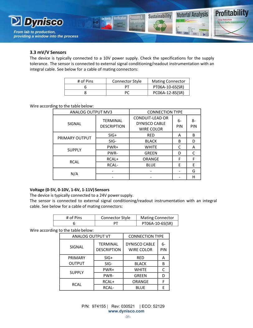
3.3 mV/V Sensors The device is typically connected to a 10V power supply. Check the specifications for the supply tolerance. The sensor is connected to external signal conditioning/readout instrumentation with an integral cable. See below for a cable of mating connectors:
# of Pins Connector Style Mating Connector
6 PT PT06A‐10‐6S(SR)
8 PC PC06A‐12‐8S(SR)
Wire according to the table below:
ANALOG OUTPUTMV3 CONNECTION TYPE
SIGNAL
TERMINAL DESCRIPTION
CONDUIT‐LEAD OR DYNISCO CABLE WIRE COLOR
6‐ PIN
8‐ PIN
PRIMARY OUTPUT SIG+ RED A B
SIG‐ BLACK B D
SUPPLY PWR+ WHITE C A
PWR‐ GREEN D C
RCAL RCAL+ ORANGE F F
RCAL‐ BLUE E E
N/A ‐ ‐ ‐ G
‐ ‐ ‐ H
Voltage (0‐5V, 0‐10V, 1‐6V, 1‐11V) Sensors The device is typically connected to a 24V power supply. The sensor is connected to external signal conditioning/readout instrumentation with an integral cable. See below for a cable of mating connectors:
# of Pins Connector Style Mating Connector
6 PT PT06A‐10‐6S(SR)
Wire according to the table below:
ANALOG OUTPUT VT CONNECTION TYPE
SIGNAL TERMINAL
DESCRIPTIONDYNISCO CABLE WIRE COLOR
6‐ PIN
PRIMARY OUTPUT
SIG+ RED A
SIG‐ BLACK B
SUPPLY PWR+ WHITE C
PWR‐ GREEN D
RCAL RCAL+ ORANGE F
RCAL‐ BLUE E

P/N: 974155 | Rev: 030521 | ECO: 52129 www.dynisco.com
From lab to production, providing a window into the process
-32-
Optional Thermocouple Temperature Indication
Dynisco follows industry standard colors and connectors for thermocouples.
Use extension wire to connect the thermocouple output to the measurement system. Extension grade wires are made of the same metals as a higher‐grade thermocouple wire. They are used to connect it to a measuring instrument some distance away without introducing additional junctions between dissimilar materials. It is important to match your extension wire type to your thermocouple element type. Otherwise, errors can be introduced into your system.
P/N: 974155 | Rev: 030521 | ECO: 52129 www.dynisco.com
From lab to production, providing a window into the process
-33-
7 COMMISSIONING
7.1 WHY A SENSOR SHOULD BE REZEROED ................................................................................................... 32
7.2 UTILIZING THE ZERO AND SPAN ACTUATORS .......................................................................................... 32
7.3 AVOID COLD STARTS! .............................................................................................................................. 33
7.4 THE OPTIONAL TEMPERATURE OUTPUT ................................................................................................. 33
7.5 Rcal OUTPUT ............................................................................................................................................ 34
7.1 WHYASENSORSHOULDBEREZEROED The sensor output must be nulled at zero pressure after installation when the machine has stabilized at operating temperature to correct for temperature effects as well as orientation, torque, side loading, etc. All of these effects can be compensated for by setting the sensor zero after the machine has stabilized at operating temperature.
Typically, your instrumentation can be used to Rezero the unit. A 4‐20mA or voltage unit can also be rezeroed locally using its actuators. 7.2 UTILIZINGTHEZEROANDSPANACTUATORS When the sensor output needs to be corrected due to mounting location and temperature shift, the zero actuator can be used. Please wait until the process has been brought to operating temperature before zeroing. The zero procedure is only recommended after the process temperature has stabilized, the snout has been tightened to the specified torque, and the sensor electronics housing has been permanently installed. Normally a Rezero is all that is required after installation since the sensor span has been calibrated at the factory. In the event the full scale output is not correct when checked against a calibrated pressure source or dead weight tester, the sensor span can be adjusted via the Span actuator. Span adjustments can only be performed when applying a known calibrated full scale pressure to the sensor. The span actuator should never be used without zeroing the sensor with the zero actuator first.
Do not adjust the Span potentiometer while Rcal is engaged!
ZERO AND SPAN PROCEDURE 1. Connect Power Supply and readout electronics to Vertex sensor.
2. If commissioning on the bench with a dead weight tester or calibrated pressure source, ensure pressure connection is free of leaks.
3. Apply power to the Vertex sensor and observe output with zero pressure applied. The output should indicate zero pressure. If not, proceed to step 4.
4. Perform Zero Function
mV/V units can only be zeroed when this feature is available on your indicator/controller. No
local zero capability.
Voltage units can be zeroed using on board zero potentiometer. Remove seal screw and adjust potentiometer until desired output is achieved. Replace seal screw when complete.
P/N: 974155 | Rev: 030521 | ECO: 52129 www.dynisco.com
From lab to production, providing a window into the process
-34-
mA units have a variety of on board Zero Adjustments types (based on configuration), i.e. potentiometer, pushbuttons, and HALL Effect Switches.
o For units with potentiometers, remove seal screw and adjust potentiometer until desired output is achieved. Replace seal screw when complete.
o For units with pushbuttons, remove seal screw, using a 2mm or smaller Allen Key, depress pushbutton for ½ sec, release pushbutton for ½ sec, depress pushbutton for ½ sec and release. Replace seal screw when complete.
o For units with HALL Effect Switches, unthread zero screw from endplate, depress screw, release screw, depress screw, release screw and return screw in endplate (failure to return the screw on units with HALL Effects Switches will cause the unit to go into failsafe).
5. Steps past this point are not part of a normal bench setup and should only be performed by qualified individuals. The Vertex sensor has been factory calibrated with highly accurate pressure generators. Span adjustment should only be performed on a calibrated pressure generator at 100%FS.
6. Apply Full Scale pressure and verify output. If output indication is incorrect, adjust the span
potentiometer.
7.3 AVOIDCOLDSTARTS!
In plastics, both the sensor and extruder can be damaged if the extruder is not brought up to operating temperature before the machinery begins operating. A sufficient “soak time” must be provided for the plastic to go from its solid to molten state before the extruder drive is started.
7.4 THEOPTIONALTEMPERATUREOUTPUT
The sensor can also detect the temperature of the tip. J and K thermocouple outputs are available as an option. The thermocouple is an integral part of the sensor/flex assembly and must be specified when ordering the sensor. Thermocouple extension wire should be used between the sensor and the thermocouple indicator for best accuracy. Changes in metallurgy along the length of the thermocouple wiring (such as terminal strips or changes in thermocouple type wire) will introduce another undesirable thermocouple junction (which may affect the measurement.)

P/N: 974155 | Rev: 030521 | ECO: 52129 www.dynisco.com
From lab to production, providing a window into the process
-35-
7.5 RcalOUTPUT An optional shunt calibration/Rcal output is also available. Rcal is a method of generating an electrical output to match the electrical output that would be given in response to an applied pressure. Rcal is normally set to 80%FS so that all similar sensors calibrate at the same point to facilitate interchangeability.
The Rcal pins on the sensor are normally left open. When the pins are electrically shorted, the sensor will simulate an applied pressure of 80% of the sensor full scale output. This eliminates the need for a cumbersome calibrated pressure source when scaling associated instrumentation.
The purpose of Rcal is to make it possible to match the sensor to the Pressure Indicator/Controller with a “two point calibration.” (Two points define a line.) Setting up the instrument in this fashion is much more accurate through a single point offset adjustment.
When the sensor is fully installed and the machine is at operating temperature and at zero pressure, the indicator may be “zeroed” using whatever mechanism nulls it. Afterward, the Rcal pins on the sensor may be shorted to simulate a pressure of 80% full scale to complete the calibration and allow the indicator span to be adjusted.
Caution ‐ Do not adjust Span with Rcal activated. The Rcal signal of Vertex is a fixed voltage added to the Zero Output. It is not influenced by Span potentiometer adjustments!

P/N: 974155 | Rev: 030521 | ECO: 52129 www.dynisco.com
From lab to production, providing a window into the process
-36-
8 UTILIZINGTHEHARTCOMMUNICATIONS
8.1 CONNECTING THE HART HANDHELD COMMUNICATOR ................................................................... 36
8.2 ALARM & SATURATION VALUES BURST MODE ................................................................................. 39
8.3 ALARM & SATURATION VALUES IN MULTIDROP MODE ................................................................... 39
8.4 TRANSMITTER FUNCTIONS VIA HART ............................................................................................... 40
8.5 RERANGING VIA HART ....................................................................................................................... 42
8.6 RESETTING TO FACTORY DEFAULT SETTINGS ................................................................................... 44
8.7 DEFINITION OF “RESTORE FACTORY DEFAULTS” .............................................................................. 45
8.8 HART COMMUNICATOR FAST KEY SEQUENCES ................................................................................ 45
The zero procedure is only recommended after the process temperature has stabilized and the electronics housing has been permanently installed. When the zero trim function is selected (HART Quick key 1,2,5,1,3,1) the output will be corrected to reflect zero pressure. This is done by the transmitter electronics automatically by adjusting digital PV to zero and analog output will be 4 mA. Normally a Zero Trim is all that is required after installation since the Transmitter span has been calibrated at the factory. In the event the Full Scale output is not correct when checked against a calibrated pressure source or dead weight tester, the Transmitter span can be adjusted by performing the Sensor Trim function. This is performed by first applying Zero Pressure and selecting Lower Sensor Trim (HART Quick Key 1, 2, 5, 1, 3, 2) and following the prompts on the HART Communicator. When complete, apply a known calibrated full scale pressure to the Transmitter and selecting Upper Sensor Trim (HART Quick Key 1, 2, 5, 1, 3, 3) and follow the prompts on the HART Communicator. When complete, the transmitter electronics will have adjusted the digital PV to correct to full scale output.
Never perform upper sensor trim without performing lower sensor trim first.
ATTENTION
P/N: 974155 | Rev: 030521 | ECO: 52129 www.dynisco.com
From lab to production, providing a window into the process
-37-
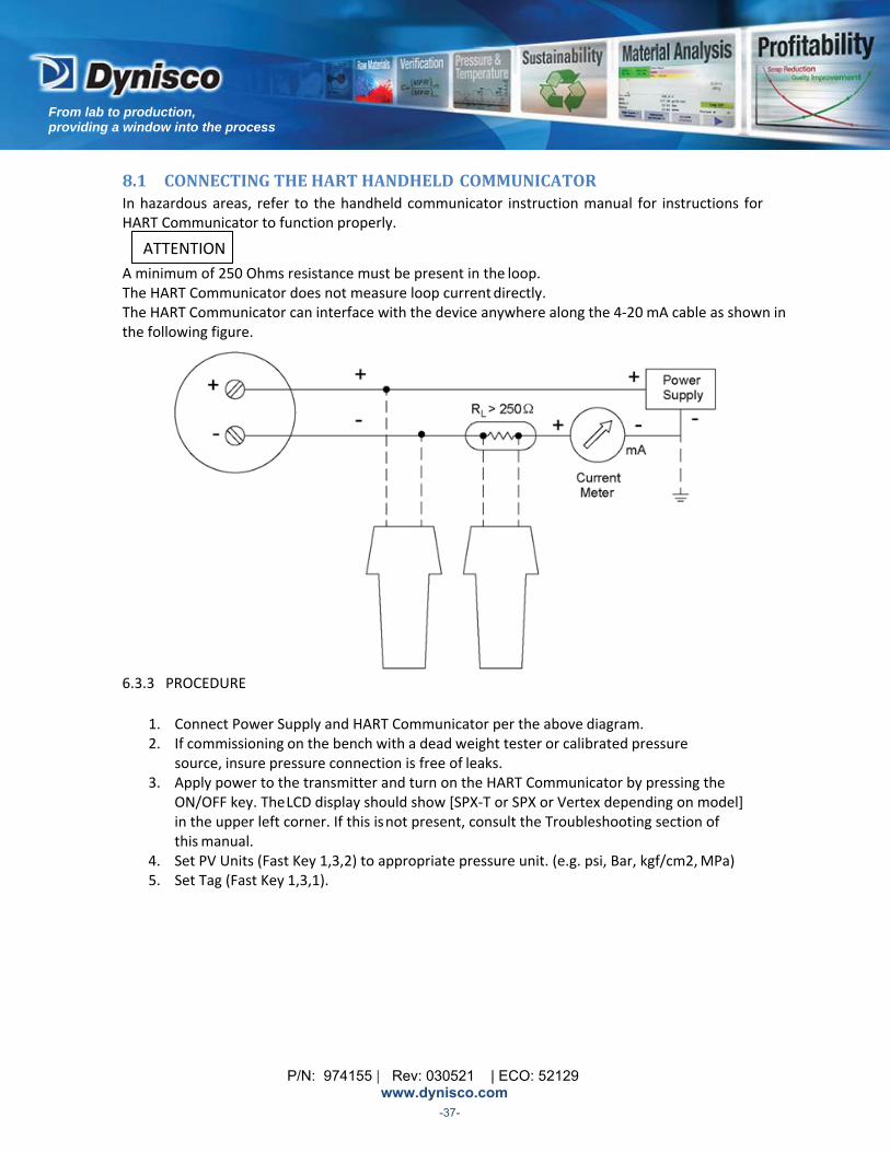
8.1 CONNECTINGTHEHARTHANDHELDCOMMUNICATOR In hazardous areas, refer to the handheld communicator instruction manual for instructions for HART Communicator to function properly.
A minimum of 250 Ohms resistance must be present in the loop. The HART Communicator does not measure loop current directly. The HART Communicator can interface with the device anywhere along the 4‐20 mA cable as shown in the following figure.
6.3.3 PROCEDURE
1. Connect Power Supply and HART Communicator per the above diagram. 2. If commissioning on the bench with a dead weight tester or calibrated pressure
source, insure pressure connection is free of leaks. 3. Apply power to the transmitter and turn on the HART Communicator by pressing the
ON/OFF key. The LCD display should show [SPX‐T or SPX or Vertex depending on model] in the upper left corner. If this is not present, consult the Troubleshooting section of this manual.
4. Set PV Units (Fast Key 1,3,2) to appropriate pressure unit. (e.g. psi, Bar, kgf/cm2, MPa) 5. Set Tag (Fast Key 1,3,1).
ATTENTION
P/N: 974155 | Rev: 030521 | ECO: 52129 www.dynisco.com
From lab to production, providing a window into the process
-38-
6. If transmitter output needs to be re‐ranged, set the appropriate LRV (Fast Key 4,1) and URV (Fast Key 4,2)
Note: URV cannot be turned down below the PV Minimum span (Fast Key 1,4,1,5) 7. Set Lower Trim (Fast Key 1,2,5,1,3,1) 8. Verify the transmitter output. Zero pressure output should read 4 mA.
Steps past this point are not part of a normal bench setup and should only be performed by qualified individuals, as the device is highly stable and has been factory calibrated with highly accurate pressure generators. This function should only be performed on such equipment.
9. Next, using calibrated pressure source, apply pressure equal to value set in URV in step 6.
Output should equal 20 mA. If output does not equal 20 mA proceed to step 10. 10. To calibrate full scale output, first apply pressure equal to full scale pressure of unit.
Next perform Upper Sensor Trim (Fast Key 1,2,5,1,3,2). Output should now equal full scale pressure.
11. If Transmitter Output Damping is required, set PV Damping (Fast Key 1,3,5) to the appropriate value.
12. Press the left arrow key until the HART Communicator is off‐line then turn the power off.
The pressure transmitter is now ready to be installed in the process.
ATTENTION
P/N: 974155 | Rev: 030521 | ECO: 52129 www.dynisco.com
From lab to production, providing a window into the process
-39-
The device has a 4‐20 mA output proportional to pressure for normal operating conditions. However, unlike a traditional sensor, the device performs self‐diagnostic routines continually during operation. If a special condition is detected, the transmitter drives its analog output outside the normal saturation values to indicate that investigation is necessary. (This condition is called fail‐safe mode alarm.) The conditions detected by the self‐diagnostic routines (and the corresponding effect on the analog output) are listed later in this section.
When a special condition is detected, the device goes into fail‐safe mode and the transmitter output goes high, by default. However, using a HART communicator, the transmitter can also be configured to drive its output low or to freeze the output where it was just before the fail‐safe was detected. The actual analog output levels are indicated below.
A low alarm (3.6 mA) is possible but not recommended because HART communications are not guaranteed until the cause of the alarm is removed.
Using the HART communicator, the specific condition that triggered the fail‐safe mode alarm can be read for diagnostic purposes. (See Status in the HART menu tree.)
In a fail‐safe condition the PV is not affected and can still be read using the handheld HART communicator. For process related fail‐safe conditions, the transmitter will remain in the alarm state until the source of error disappears. If certain electronics errors are detected, the fail‐safe condition will latch until a reset is performed by either cycling the power or through a software command.
NAMUR Compliant Saturation and Alarm Values
4 ‐ 20 mA Saturation 4 ‐ 20 mA Alarm
Low 3.8 mA 3.6 mAHigh 20.5 mA >21 mA
You can alter the actual transmitter mA output values by performing an analog output trim using the HART Communicator.
When a transmitter is in an alarm condition, the analog output displayed by the handheld indicates the alarm value of the analog output – NOT the value the transmitter would have, if the sensor had not detected the failure.
P/N: 974155 | Rev: 030521 | ECO: 52129 www.dynisco.com
From lab to production, providing a window into the process
-40-
Special Conditions and the Corresponding Analog Output Condition Alarm Value (fail safe) EEPROM failure detected Set to configured fail safe mode Cold start Set to fail safe mode low Pressure above upper limit Unchanged Pressure below lower limit Unchanged Electronics temp above upper limit Unchanged Electronics temp above lower limit Unchanged Strain gage open detected Set to configured fail safe mode Analog output saturated Unchanged
Watchdog error detected Unchanged
Zero/Span Actuator stuck Set to configured fail safe mode Low voltage detected Unchanged Outside URV or LRV Unchanged Rcal simulation on Unchanged
8.2 ALARM&SATURATIONVALUESBURSTMODE No special requirements are defined for the burst mode.
8.3 ALARM&SATURATIONVALUESINMULTIDROPMODE If the device is in multidrop mode, the NAMUR levels are no longer achievable. Instead the fail safe condition is indicated by the field device status and the additional diagnostics.
P/N: 974155 | Rev: 030521 | ECO: 52129 www.dynisco.com
From lab to production, providing a window into the process
-41-
8.4 TRANSMITTERFUNCTIONSVIAHART Zero Trim (1,2,5,1,3,1) Digital Correction to zero which affects the digital output. This differs from Lower Sensor Trim in that zero trim is ONLY performed at zero pressure. Lower Sensor Trim (1,2,5,1,3,2) Digital Correction to zero which affects the digital output. This differs from Zero Trim in that Lower Sensor Trim can be performed at pressures above zero.Note: This must be performed before Upper Sensor Trim. Only perform this function with a known calibrated pressure source.
Upper Sensor Trim (1,2,5,1,3,3) Digital correction to Full Scale which affect digital output. Note: Lower Sensor Trim must be performed before Upper Sensor Trim. Only perform this function with a known calibrated pressure source. Digital to Analog trim (1,2,5,1,2) This is used to match the digital representation of the analog output with its actual analog loop current. Note: This should only be performed with a known Calibrated Current (mA) meter. Reranging The device allows for the 4 mA and 20 mA points (LRV and URV respectively) to be adjusted so that output resolution can be improved. A Re‐range or “Turndown” ratio of 6:1 is possible. Accuracy specifications remain dependent upon the Full Sensor Range without any turndown applied. Three methods of Re‐ ranging the transmitter are outlined below. Note: If pressure applied to the transmitter is not in the range of the 6:1 turndown ratio, the transmitter will reject the Span attempt. This will be indicated by the output not adjusting to 20 mA after a few attempts using the Span Actuator. Reranging TV (MPT option only) On a device with the MPT option, there is a second 4‐20mA output that is proportional to the snout temperature. By default the TV LRV and TV URV are set to 0 and 400C respectively. The secondary 4‐20mA output can be reranged by changing TV LRV and TV URV. Reranging via Zero/Span Actuators When HART Communication is not used, LRV and URV values are entered by applying zero pressure to the device and “Rezeroing” by:
a. For units with Pushbuttons
i. Do not remove seal screw when the circuit is live in a hazardous area.
ii. Remove zero pushbutton seal screw.
iii. Using a 2mm or smaller Allen key, depress the pushbutton for a ½ second.
iv. Release pushbutton for a ½ second.
v. Depress the pushbutton again for a ½ second and release.
P/N: 974155 | Rev: 030521 | ECO: 52129 www.dynisco.com
From lab to production, providing a window into the process
-42-
b. For units with HALL Switches
i. Unthread Zero screw from endplate
ii. Depress screw
iii. Release screw
iv. Depress screw
v. Release screw
vi. Restore screw in endplate
Note: The screw must be threaded into the endplate for normal operation. Failing to do so will cause the device to go into failsafe. The LRV and URV have now been adjusted to zero the device without affecting the span. After Rezeroing, it is possible to set the span by adjusting the URV with the span actuator. The span actuator should never be used to adjust the URV without using the zero actuator to set the LRV first.
URV or Full Scale Turndown is performed by applying any pressure, within the 6:1 ratio of the transmitter that you want to be the 20 mA point. When the pressure is held steady: a. For units with Pushbuttons
i. Do not remove seal screw when the circuit is live in a hazardous area.
ii. Remove span pushbutton seal screw.
iii. Using a 2mm or smaller Allen key, depress the pushbutton for a ½ second.
iv. Release pushbutton for a ½ second.
v. Depress the pushbutton again for a ½ second and release.
b. For units with HALL Switches
i. Unthread Span screw from endplate
ii. Depress screw
iii. Release screw
iv. Depress screw
v. Release screw
vi. Restore screw in endplate
Note: The screw must be threaded into the endplate for normal operation. Failing to do so will cause the device to go into failsafe.
The device has now adjusted the URV 20 mA point to match the pressure applied.

P/N: 974155 | Rev: 030521 | ECO: 52129 www.dynisco.com
From lab to production, providing a window into the process
-43-
8.5 RERANGINGVIAHART
Rerange LRV (4) This is the pressure at which the transmitter will output 4 mA as entered directly by the user. Changing the LRV affects the transmitter span so the is range is limited by the minimum span value found in Fast Key (1,4,1,5)
Rerange URV (5)
This is the pressure at which the transmitter will output 20 mA as entered directly by the user. This range is limited by the minimum span value found in Fast Key (1,4,1,5)
Rerange TV LRV (1,3,3,3) MPT option only This is the temperature at which the transmitter will output 4 mA on the secondary mA output as entered directly by the user.
Rerange TV URV (1,3,3,4) MPT option only
This is the temperature at which the transmitter will output 20 mA on the secondary mA output as entered directly by the user.
Rerange LRV By Applying Pressure (1,2,5,1,1,1,1) This is done by applying a known pressure and initiating the procedure so that the transmitter adopts the pressure as the 4 mA point.
Note: This should only be performed with a Calibrated Pressure Source. Rerange URV By Applying Pressure (1,2,5,1,1,1,2) This is done by applying a known pressure and initiating the procedure so that the transmitter adopts the pressure as the 20 mA point. Note: This should only be performed with a Calibrated Pressure Source. Recall Factory Trim (1,2,5,3) This is used to restore the Zero, Lower, and Upper Trim to the Values as set from the Factory.
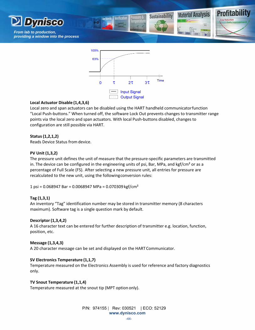
R‐Cal Set % (1,2,5,1,4,1) This is used on versions with a Rcal. By activating R‐Cal, the output will be set to the percentage of span set by this function. Default is 80%. Setting Rcal to 0%, disables the Rcal function. Damping (1,3,5) The damping time constant affects the speed with which the primary output signal reacts to changes in pressure as shown in the figure on the following page. Damping is off by default but values between 0 and 30 seconds can be set using the handheld communicator. The damping value must be entered in integers. If non‐integers are entered, the system rounds to the next integer.
P/N: 974155 | Rev: 030521 | ECO: 52129 www.dynisco.com
From lab to production, providing a window into the process
-44-
Local Actuator Disable (1,4,3,6) Local zero and span actuators can be disabled using the HART handheld communicator function “Local Push‐buttons.” When turned off, the software Lock Out prevents changes to transmitter range points via the local zero and span actuators. With local Push‐buttons disabled, changes to configuration are still possible via HART.
Status (1,2,1,2) Reads Device Status from device. PV Unit (1,3,2) The pressure unit defines the unit of measure that the pressure‐specific parameters are transmitted in. The device can be configured in the engineering units of psi, Bar, MPa, and kgf/cm² or as a percentage of Full Scale (FS). After selecting a new pressure unit, all entries for pressure are recalculated to the new unit, using the following conversion rules: 1 psi = 0.068947 Bar = 0.0068947 MPa = 0.070309 kgf/cm²
Tag (1,3,1) An inventory “Tag” identification number may be stored in transmitter memory (8 characters maximum). Software tag is a single question mark by default. Descriptor (1,3,4,2) A 16 character text can be entered for further description of transmitter e.g. location, function, position, etc. Message (1,3,4,3) A 20 character message can be set and displayed on the HART Communicator.
SV Electronics Temperature (1,1,7) Temperature measured on the Electronics Assembly is used for reference and factory diagnostics only. TV Snout Temperature (1,1,4) Temperature measured at the snout tip (MPT option only).
P/N: 974155 | Rev: 030521 | ECO: 52129 www.dynisco.com
From lab to production, providing a window into the process
-45-
Poll Address (1,4,3,3,3) Use in Multidrop mode allows more than one transmitter (up to 15) on a single loop. If this value is other than zero, the transmitter is in Multidrop mode. An example of Multidrop mode would be a group of HART devices wired in parallel on a single powered loop and each device being assigned a unique Poll address (1‐15). The HART communicator would prompt for the individual address of the transmitter to communicate with and would only poll that specific device. All others would remain unchanged. Note: Analog output is set to 4mA when in multi‐drop mode.
Burst Mode (1,4,2,3,1) When the device is used in Burst Mode, the transmitter outputs one‐way digital communications from the transmitter to the Host. Communication rate is faster since the transmitter does not have to be polled to send data. Information transmitted in Burst Mode includes Pressure Variable, Analog Output value, Pressure in % of range. Access to other information can still be obtained through normal HART Comms. 8.6 RESETTINGTOFACTORYDEFAULTSETTINGS
The factory settings for the sensor (including zero and span) can be restored if they are changed inadvertently using the Zero/Span Actuators or the HART communicator. The list of parameters restored is shown below.
Make sure Control System is in Manual mode. Temporary loss of Loop Output during Electronics Re‐boot may occur.
To reset the sensor using the actuators, use the following procedure:
a. For units with Pushbuttons
i. Do not remove seal screw when the circuit is live in a hazardous area.
ii. Remove zero and span pushbutton seal screws.
iii. Using a 2mm or smaller Allen key, depress the pushbuttons for a ½ second.
iv. Release pushbuttons for a ½ second.
v. Depress the pushbuttons again for a ½ second and release.
b. For units with HALL Switches
i. Unthread Zero and Span screws from endplate
ii. Depress screws
iii. Release screws
iv. Depress screws
v. Release screws
vi. Restore screws in endplate
Note: The screws must be threaded into the endplate for normal operation. Failing to do so will cause the device to go into failsafe. At this point, the LRV and URV will be set to factory defaults.
P/N: 974155 | Rev: 030521 | ECO: 52129 www.dynisco.com
From lab to production, providing a window into the process
-46-
8.7 DEFINITIONOF“RESTOREFACTORYDEFAULTS” 1. Restore LRV and URV to their values at shipment.
2. Restore the Pressure Unit (psi, Bar, etc.) to its value at shipment.
3. Set the Analog Output Alarm Level to its value at shipment.
4. Remove all Pressure Damping
5. Clear all Sensor and Analog Output Trim values.
6. Clear Burst Mode.
7. Restore the Address to Zero.
8. Restore the Rcal option to its value at shipment. (Enable or Disable the Rcal option.)
9. Set actuators to the settings they were when shipped from DYNISCO.
8.8 HARTCOMMUNICATORFASTKEYSEQUENCES Below defines the HART Communicator Fast Key sequences. Fast Keys are a means of supplying a shortcut to navigate through the menu tree. HART Communicator Fast Key sequences
Function Fast Key Sequence
Read PV Pressure 2
Read % of Full Scale 1,1,2
Read Analog Output (PV) 1,1,3
Read SV Electronics Temperature 1,1,7
Read Peak Pressure Value 1,2,1,2
Read Peak Electronic Temp Value (SV) 1,2,1,3
Read Sensor Diagnostic Status 1,2,1,1
Read PV Minimum Span 1,4,1,5
Perform Sensor Self‐Test 1,2,2
Perform Sensor Master Reset 1,2,3
Perform Loop Test 1,2,4
Perform D/A Trim (PV) 1,2,5,1,2
Perform Zero Trim 1,2,1,3,1
Perform Lower Sensor Trim 1,2,5,1,3,2
Perform Upper Sensor Trim 1,2,5,1,3,3
Recall Factory Trim 1,2,5,3
Set Rcal % 1,2,5,1,4,1
Set Tag 1,3,1
Set PV Unit 1,3,2
Set Lower Range Value (LRV) (PV) 1,3,3,1
Set Upper Range Value (URV) (PV) 1,3,3,2
Display Lower Set Limit (LSL) (PV) 1,3,3,5
Display Upper Set Limit (USL) (PV) 1,3,3,6
Set Date 1,3,4,1
Set Descriptor 1,3,4,2
Set Message 1,3,4,3
Set PV Damping 1,3,5
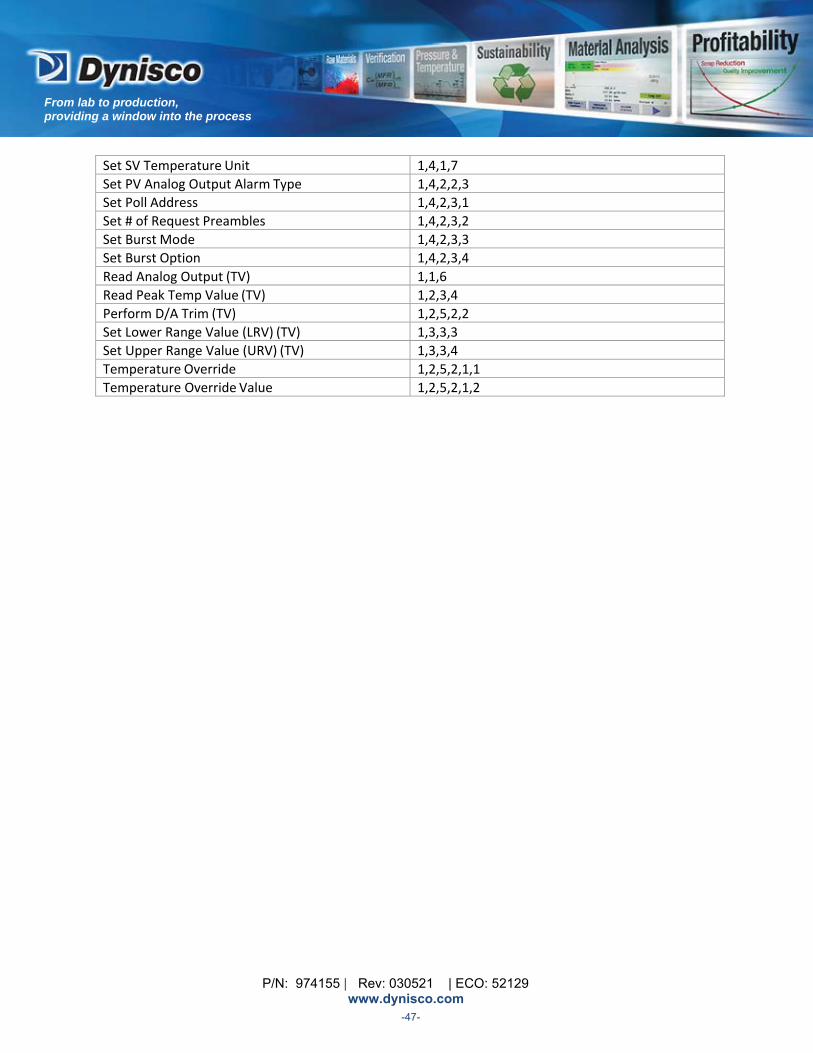
P/N: 974155 | Rev: 030521 | ECO: 52129 www.dynisco.com
From lab to production, providing a window into the process
-47-
Set SV Temperature Unit 1,4,1,7
Set PV Analog Output Alarm Type 1,4,2,2,3
Set Poll Address 1,4,2,3,1
Set # of Request Preambles 1,4,2,3,2
Set Burst Mode 1,4,2,3,3
Set Burst Option 1,4,2,3,4
Read Analog Output (TV) 1,1,6
Read Peak Temp Value (TV) 1,2,3,4
Perform D/A Trim (TV) 1,2,5,2,2
Set Lower Range Value (LRV) (TV) 1,3,3,3
Set Upper Range Value (URV) (TV) 1,3,3,4
Temperature Override 1,2,5,2,1,1
Temperature Override Value 1,2,5,2,1,2
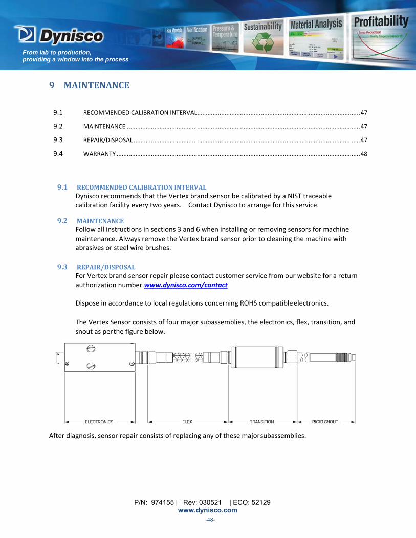
P/N: 974155 | Rev: 030521 | ECO: 52129 www.dynisco.com
From lab to production, providing a window into the process
-48-
9 MAINTENANCE
9.1 RECOMMENDED CALIBRATION INTERVAL ............................................................................................... 47
9.2 MAINTENANCE ........................................................................................................................................ 47
9.3 REPAIR/DISPOSAL .................................................................................................................................... 47
9.4 WARRANTY .............................................................................................................................................. 48
9.1 RECOMMENDEDCALIBRATIONINTERVAL Dynisco recommends that the Vertex brand sensor be calibrated by a NIST traceable calibration facility every two years. Contact Dynisco to arrange for this service.
9.2 MAINTENANCE Follow all instructions in sections 3 and 6 when installing or removing sensors for machine maintenance. Always remove the Vertex brand sensor prior to cleaning the machine with abrasives or steel wire brushes.
9.3 REPAIR/DISPOSAL
For Vertex brand sensor repair please contact customer service from our website for a return authorization number.www.dynisco.com/contact
Dispose in accordance to local regulations concerning ROHS compatible electronics.
The Vertex Sensor consists of four major subassemblies, the electronics, flex, transition, and snout as per the figure below.
After diagnosis, sensor repair consists of replacing any of these major subassemblies.

P/N: 974155 | Rev: 030521 | ECO: 52129 www.dynisco.com
From lab to production, providing a window into the process
-49-
9.4 WARRANTY
The Vertex brand sensor Series Dynisco Pressure Sensors will provide excellent service and superior performance if proper care is taken during handling, installation, and use. This DYNISCO product is warranted under terms and conditions set forth in the Dynisco web pages. Go to www.dynisco.com and click on the "warranty" link under the “Post‐Sales Support” tab at the top of the web page for complete details.
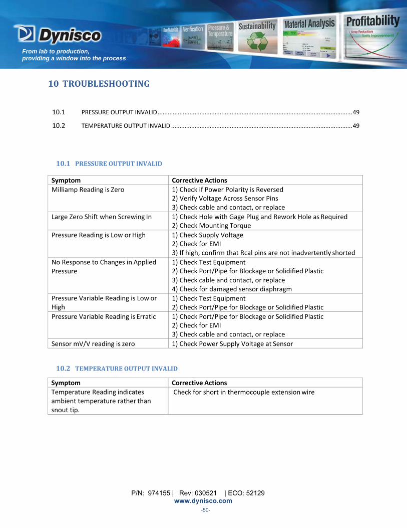
P/N: 974155 | Rev: 030521 | ECO: 52129 www.dynisco.com
From lab to production, providing a window into the process
-50-
10 TROUBLESHOOTING
10.1 PRESSURE OUTPUT INVALID .................................................................................................................... 49
10.2 TEMPERATURE OUTPUT INVALID ............................................................................................................ 49
10.1 PRESSUREOUTPUTINVALID
Symptom Corrective Actions
Milliamp Reading is Zero 1) Check if Power Polarity is Reversed 2) Verify Voltage Across Sensor Pins 3) Check cable and contact, or replace
Large Zero Shift when Screwing In 1) Check Hole with Gage Plug and Rework Hole as Required 2) Check Mounting Torque
Pressure Reading is Low or High 1) Check Supply Voltage 2) Check for EMI 3) If high, confirm that Rcal pins are not inadvertently shorted
No Response to Changes in Applied Pressure
1) Check Test Equipment 2) Check Port/Pipe for Blockage or Solidified Plastic 3) Check cable and contact, or replace 4) Check for damaged sensor diaphragm
Pressure Variable Reading is Low or High
1) Check Test Equipment 2) Check Port/Pipe for Blockage or Solidified Plastic
Pressure Variable Reading is Erratic 1) Check Port/Pipe for Blockage or Solidified Plastic 2) Check for EMI 3) Check cable and contact, or replace
Sensor mV/V reading is zero 1) Check Power Supply Voltage at Sensor
10.2 TEMPERATUREOUTPUTINVALID
Symptom Corrective Actions
Temperature Reading indicates ambient temperature rather than snout tip.
Check for short in thermocouple extension wire

P/N: 974155 | Rev: 030521 | ECO: 52129 www.dynisco.com
From lab to production, providing a window into the process
-51-
11 DYNISCOCONTACTINFORMATION
Please visit our website for up to date contact information: www.dynisco.com/contact
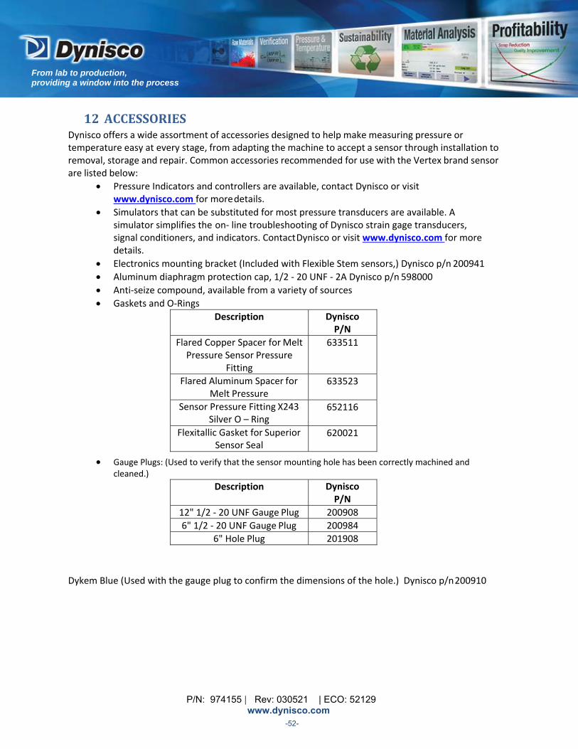
P/N: 974155 | Rev: 030521 | ECO: 52129 www.dynisco.com
From lab to production, providing a window into the process
-52-
12 ACCESSORIES Dynisco offers a wide assortment of accessories designed to help make measuring pressure or temperature easy at every stage, from adapting the machine to accept a sensor through installation to removal, storage and repair. Common accessories recommended for use with the Vertex brand sensor are listed below:
Pressure Indicators and controllers are available, contact Dynisco or visit www.dynisco.com for more details.
Simulators that can be substituted for most pressure transducers are available. A simulator simplifies the on‐ line troubleshooting of Dynisco strain gage transducers, signal conditioners, and indicators. Contact Dynisco or visit www.dynisco.com for more details.
Electronics mounting bracket (Included with Flexible Stem sensors,) Dynisco p/n 200941
Aluminum diaphragm protection cap, 1/2 ‐ 20 UNF ‐ 2A Dynisco p/n 598000
Anti‐seize compound, available from a variety of sources
Gaskets and O‐Rings
Description Dynisco P/N
Flared Copper Spacer for Melt Pressure Sensor Pressure
Fitting
633511
Flared Aluminum Spacer for Melt Pressure
633523
Sensor Pressure Fitting X243 Silver O – Ring
652116
Flexitallic Gasket for Superior Sensor Seal
620021
Gauge Plugs: (Used to verify that the sensor mounting hole has been correctly machined and cleaned.)
Description Dynisco P/N
12" 1/2 ‐ 20 UNF Gauge Plug 200908
6" 1/2 ‐ 20 UNF Gauge Plug 200984
6" Hole Plug 201908
Dykem Blue (Used with the gauge plug to confirm the dimensions of the hole.) Dynisco p/n 200910

P/N: 974155 | Rev: 030521 | ECO: 52129 www.dynisco.com
From lab to production, providing a window into the process
-53-
Transducer Mounting Hole Tool kits
o Machining a mounting port: 1/2 ‐ 20 UNF sensor mounting hole machining tool kit, Dynisco p/n 200925. The Transducer Mounting Hole Machining Tool Kit contains all of the necessary drills and taps to prepare a standard 1/2 ‐ 20 UNF transducer mounting hole. The kit contains the special pilot drill required to machine the 45 degree seat. All tools included in this kit are made of premium grade, high strength tool steel. Consult factory for tool kits for other port configurations.
o Spare 29/64 Pilot Drill (included in Machining Tool Kit) Dynisco p/n200924
o Cleaning: 1/2 ‐ 20 UNF sensor mounting hole cleaning tool kit, Dynisco p/n 200100. The
cleaning tool kit was designed for use in removing excess plastic from mounting holes for pressure and temperature sensors. Installation of sensors into improperly cleaned or sized holes is one of the major causes of damage to the sensors. Consult factory for tool kits for other port configurations.
P/N: 974155 | Rev: 030521 | ECO: 52129 www.dynisco.com
From lab to production, providing a window into the process
-54-
Cables and Connectors
o The cable assemblies provide the electrical hookup from the sensor to the display
instrumentation. The assemblies consist of a sensor mating connector and a length of shielded, 6 conductor cable with stripped leads.
o 6 pin (Bendix PT06A‐10‐6S(SR) Connector) cable assemblies for 6‐pin sensors (not for
IP67 units)
Length (ft)
Dynisco P/N
10 929008
20 929020
40 929022
60 929024
80 929025
100 929026
o For IP67 units that have connectors:
6‐Pin (PT) 8‐Pin (PT) 8‐Pin (PC) Length (ft) Part No. Length (ft) Part No. Length (ft) Part No.
20 801850 20 801141 Contact Factory 40 801851 100 80174460 801852 80 801853 100 801854 120 801855 140 801856 160 801857 250 801858 5 801859
P/N: 974155 | Rev: 030521 | ECO: 52129 www.dynisco.com
From lab to production, providing a window into the process
-55-
o Accessories to retrofit sensor to existing cabling: 1' Cable Assembly
To Adapt 6‐pin sensors to existing Mating Connector and Wiring for 8‐pin sensors, Dynisco p/n 800860
Connector only:
Cable Mounted 6 ‐ Pin Connecter, Dynisco p/n 711170
o Bulk cable: 6 Conductor, 22 AWG, Braided RFI Shielded Cable, Thermoplastic Rubber Jacket,
Dynisco p/n 800024 Teflon‐Coated Cable, 6 ‐ Conductor for High Temperature Applications, Dynisco p/n 800005
o Connectors: Bendix PT06A ‐ 10 ‐ 6S (SR) 6 Socket, Cable Mount, Dynisco p/n 711600
o Thermocouple connectors: Type J Thermocouple, Female Connector Only, Dynisco p/n 753000 Type J Thermocouple, Male Connector Only, Dynisco p/n 753001 Type K Thermocouple, Female Connector Only, Dynisco p/n 753007 Type K Thermocouple, Male Connector Only, Dynisco p/n 753008
o Thermocouple extension wire… Available from a variety of sources
1/2‐20 Type L Adaptor An adaptor can be ordered which would allow mounting the 1/2‐20 Vertex into a Button Seal (Taylor Bulb) port configuration. Consult factory as these are built to order.

P/N: 974155 | Rev: 030521 | ECO: 52129 www.dynisco.com
From lab to production, providing a window into the process
-56-
13 APPROVALS/CERTIFICATES 13.1 EC DECLARATION OF CONFORMITY ......................................................................................................... 56
13.2 EC‐TYPE EXAMINATION CERTIFICATE ...................................................................................................... 57

P/N: 974155 | Rev: 030521 | ECO: 52129 www.dynisco.com
From lab to production, providing a window into the process
-57-
13.1 EUDECLARATIONOFCONFORMITY
P/N: 974155 | Rev: 030521 | ECO: 52129 www.dynisco.com
From lab to production, providing a window into the process
-58-
13.2 EU‐TYPEEXAMINATIONCERTIFICATE See section 3.4
P/N: 974155 | Rev: 030521 | ECO: 52129 www.dynisco.com
From lab to production, providing a window into the process
-59-
14OUTLINEDRAWINGS

P/N: 974155 | Rev: 030521 | ECO: 52129 www.dynisco.com
From lab to production, providing a window into the process
-60-
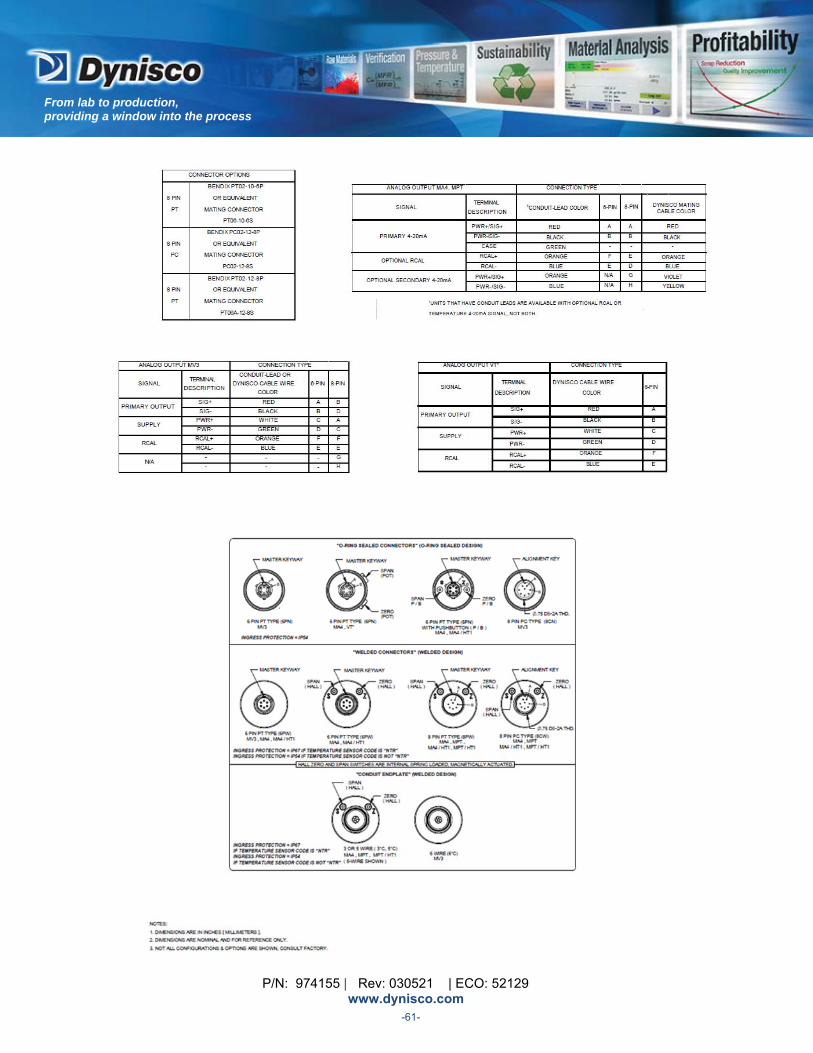
P/N: 974155 | Rev: 030521 | ECO: 52129 www.dynisco.com
From lab to production, providing a window into the process
-61-