dynjet® flex 140 - smithco.com
TRANSCRIPT

DYNA JET® FLEX 7140 INSTALLATION, SETUP AND USER GUIDE
Software Version 1.03with optional Dual Nozzle Mode

ii www.teejet.com
DynaJet® Flex 7140Table of ContentsDYNAJET® FLEX OVERVIEW 1
INSTALLATION 1CONSOLE 1
INSTALLATION 2
DynaJet Flex® Drivers ...................................................................................................................................................................................2Power ..................................................................................................................................................................................................................2Nozzle Harnesses ............................................................................................................................................................................................2CAN Cables & Terminators ...........................................................................................................................................................................2DynaJet Flex® Interface ................................................................................................................................................................................2Boom Interface Module (BIM) (optional) ...............................................................................................................................................2Pressure Sensor Interface(optional) .........................................................................................................................................................2
INITIAL STARTUP 5Favorites .............................................................................................................................................................................................................5Setup ...................................................................................................................................................................................................................5
Units .........................................................................................................................................................................................6Number of Sections .................................................................................................................................................................6Number of Nozzles ..................................................................................................................................................................6Maximum Pressure Sensor Value ...........................................................................................................................................6
Nozzle Selection ..............................................................................................................................................................................................7Select Nozzle Series ........................................................................................................................................................7Select Nozzle Capacity ....................................................................................................................................................7
Ready to Pressure Test the System ...........................................................................................................................................................7
OPERATIONS 8Work Screen ......................................................................................................................................................................................................8
On Screen Indicators ...............................................................................................................................................................8Droplet Size Chart............................................................................................................................................................8
Diagnostics .......................................................................................................................................................................................................9Error Warnings .............................................................................................................................................................................................. 10
USER SETTINGS 12
DYNAJET FLEX® NOZZLE SELECTION 14Nozzle Selection Example ........................................................................................................................................................................ 15
TUNING DYNAJET FLEX® 16Tuning the Control Console Valve ......................................................................................................................................................... 16Tuning the DynaJet Flex System ............................................................................................................................................................ 16
55295 E-CHEMSAVER® MAINTENANCE INSTRUCTIONS 17General Disassembly and Reassembly................................................................................................................................................. 17
APPLICATION RATES AT GIVEN SPEED AND NOZZLE CAPACITY 18
SPEED RANGE AVAILABLE AT GIVEN N NOZZLE SIZE AND APPLICATION RATE 20

198-05345-ENUS R1
DynaJet® Flex 7140DYNAJET® FLEX OVERVIEWThe DynaJet Flex controller works in conjunction with an existing rate controller that regulates flow via a control valve or pump regulation to achieve a target application rate while maintaining target droplet size(s) when a speed change occurs. This system only works with automatic rate controllers that use flow based monitoring systems and not pressure based monitoring systems. Automatic rate controllers equipped for both flow and pressure based control should have the pressure-based system disabled to work in conjunction with DynaJet Flex.
The independent automatic rate controller loop performs the same as it would if the DynaJet Flex controller were not present. The DynaJet Flex controller changes flow output to each individual nozzle based upon input provided from the operator about the optimum droplet size (pressure) for the application.
INSTALLATION CONSOLEThe DynaJet Flex console is designed to provide years of service under typical agricultural and turf operating conditions. A tight fitting enclosure means that typical dusty environments will not cause operational problems. While occasional splashing of water will not damage the unit, the DynaJet Flex console is not designed for direct exposure to rain. Take care not to operate the DynaJet Flex console in wet conditions.
Figure 1: DynaJet Flex 7140 Console Front and Back
to DynaJet Flex Interface Harness Connection
Power Switch
USB Port
Standard RAM Bracket
Bright Touch Screen
Safety InformationTeeJet Technologies is not responsible for damage or physical harm caused by failure to adhere to the following safety requirements.As the operator of the vehicle, you are responsible for its safe operation.
The DynaJet Flex is not designed to replace the vehicle’s operator.Be sure that the area around the vehicle is clear of people and obstacles before and during engagement.The DynaJet Flex is designed to support and improve efficiency while working in the field. The driver has full responsibility for the quality and work related results.

2 www.teejet.com
DynaJet® Flex 7140
CAN Start Terminator (female)at Boom Section 1
DynaJet Solenoids
to CAN connection
DynaJet Solenoids
Power Distribution Module
Tip Harness
DynaJet Driver
DynaJet Solenoids DynaJet Solenoids
Tip Harness
DynaJet Driver
DynaJet Solenoids DynaJet Solenoids
Tip Harness
DynaJet Driver
DynaJet Solenoids DynaJet Solenoids
Tip Harness
DynaJet Driver
INSTALLATIONDynaJet Flex® Drivers There will be one DynaJet Flex Driver 78-05124 per eight (8) nozzles.
• Mount each DynaJet Flex Driver centered within the eight (8) nozzles it controls.
PowerPower will be sourced from the battery using the 60 amp fused cable 45-05943.
Power from the battery will be routed to the boom using the 6 gauge power cables 45-05942-xx
The Power Distribution Modules 78-05121-xx will connect to the 45-05942-xx cables.
Power will then route from 78-05121-xx to each DynaJet Flex Driver 78-05122 using cables 45-05971-xx, and 45-05997-xx or 45-05998-xx.
Nozzle HarnessesWhen installing Nozzle Harnesses 45-04005-xx-xx always start with Section 1 and continue to the last section.
Nozzle Harnesses are designed for your specific nozzle spacing.
Always start with nozzle #1 and work left to right (while facing in the machine’s forward direction.
CAN Cables & TerminatorsThe Start Terminator 45-04006-START must be connected to the DynaJet Flex Driver 78-05124 for Section 1.
CAN cables must be connected in series.
The End Terminator 45-04006-END must be connected to the Driver Module 78-05124 for the last section.
DynaJet Flex® InterfaceThe DynaJet Flex Interface 78-05123 connects to the DynaJet Flex Interface Harness 45-10193:
The DynaJet Flex Interface Harness connects to
a. The Console 75-30119 (extension cable may be used)b. Power 12V for powering the CANc. CANd. Pressure Sensore. Boom Sense
The DynaJet Flex Interface can be mounted in the cab or outside depending upon your installation.
Boom Interface Module (BIM) (optional)The Boom Interface Module (BIM) 78-05091 is used by the DynaJet Flex System for boom sense.
The BIM Harness connects between the BIM and the CAN.
On the BIM Harness 45-10195, the Boom Sense Wires (or flying leads) are supplied to tie into existing machine boom section 12V ON/0V OFF outputs.
If not using 45-10195, some machine specific harnesses are available.
The BIM can be mounted in the cab or outside depending upon your installation.
Pressure Sensor Interface(optional)Pressure Sensor Interface 78-05133 can be used if the DynaJet Flex Interface is mounted in the cab and there is a substantial distance to the boom.
• The Pressure Sensor Interface should be mounted close to the boom manifold.
Figure 2: Installation Diagram

398-05345-ENUS R1
DynaJet® Flex 7140Fi
gure
3: S
yste
m D
iagra
m
(A) D
ynaJ
et 71
40 C
onso
le w/
RAM
Moun
t Kit
90
-028
87
Kit in
clude
s: Co
nsole
and
Mou
nt
(K) S
enso
r Cab
le
45-0
5887
: 3' /
1 m
45-0
5886
: 25'
/ 7.6
m
(G) P
ress
ure S
enso
r
16-0
5015 (H
) Boo
m Ha
rness
45
-101
78 to
IC18
45
-101
79 to
Rav
en 44
0
45-1
0181
to R
aven
Env
izio
45
-101
86 to
15 S
ectio
n Boo
m Ha
rnes
s(J
) CAN
Ter
mina
tor
45-0
4006
-END
(L) D
river
Har
ness
45
-040
05-0
6-20
: 6 no
zzle,
20” /
50 cm
spac
ing
45-0
4005
-06-
20-E
ND: 6
nozz
le, 20
" / 50
cm sp
acing
w/te
rmina
tion
45
-040
05-0
6-20
-STA
RT: 6
nozz
le, 20
" / 50
cm sp
acing
w/te
rmina
tion
45
-040
05-0
8-20
: 8 no
zzle,
20” /
50 cm
spac
ing
45-0
4005
-08-
20-E
ND: 8
nozz
le, 20
" / 50
cm sp
acing
w/te
rmina
tion
45
-040
05-0
8-20
-STA
RT: 8
nozz
le, 20
" / 50
cm sp
acing
w/te
rmina
tion
(M)
Nozz
le Ex
tensio
n
45-
0400
1-40
: 40"
/ 1 m
4
5-04
001-
80: 8
0" / 1
m
(I) C
AN T
erm
inator
45
-040
06-S
TART
(F) D
ynaJ
et Fle
x Driv
er
78-0
5124
(E
) CAN
Exte
nsion
Cab
le
45-0
4006
-03:
3’ / 1
m
45-0
4006
-07:
7’ / 2
m
45-0
4006
-13:
13’ /
4 m
45-0
4006
-20:
20’ /
6 m
to Ba
ttery
Powe
r
to Ba
ttery
Powe
r
to Ba
ttery
Powe
r
(C) D
ynaJ
et Fle
x Inte
rface
Har
ness
45
-101
93
(D) D
ynaJ
et Fle
x Inte
rface
78
-051
23
(B) C
onso
le Ex
tensio
n Cab
le
45-0
5900
: 5' /
1.5 m
45
-059
01: 1
0' / 3
m
45-0
5902
: 20'
/ 6 m
45
-059
03: 4
0' / 1
2 m
to Ba
ttery
Powe
r

4 www.teejet.com
DynaJet® Flex 7140Item Part # Description IllustrationA 90-02887 DynaJet Flex 7140 Console
B 45-05900: 5' / 1.5 m 45-05901: 10' / 3 m 45-05902: 20' / 6 m 45-05903: 40' / 12 m
Console Extension Cable
C 45-10193 DynaJet Flex Interface Harness
D 78-05123 DynaJet Flex Interface
E 45-04006-03: 3' / 1 m 45-04006-07: 7' / 2 m 45-04006-13: 13' / 4 m 45-04006-20: 20' / 6 m
CAN Extension Cable
F 78-05124 DynaJet Flex Driver
G 16-05015 Pressure Sensor
H 45-10178 to IC18 45-10179 to Raven 440 45-10181 to Raven Envizio 45-10186 to 15 Section Boom Harness
Boom Harness
I 45-05855 CAN Terminator-START
J 45-05856 CAN Terminator-END
K 45-05887: 3' / 1 m 45-05886: 25' / 7.6 m
Pressure Sensor Cable
L 45-04005-06-20: 6 nozzle, 20” / 50 cm spacing 45-04005-06-20-END: 6 nozzle, 20" / 50 cm spacing w/termination 45-04005-06-20-START: 6 nozzle, 20" / 50 cm spacing w/termination 45-04005-08-20: 8 nozzle, 20” / 50 cm spacing 45-04005-08-20-END: 8 nozzle, 20" / 50 cm spacing w/termination 45-04005-08-20-START: 8 nozzle, 20" / 50 cm spacing w/termination
Driver Harness
M 45-04001-40: 40" / 1 m 45-04001-80: 80" / 2 m
Nozzle Extension

598-05345-ENUS R1
DynaJet® Flex 7140INITIAL STARTUPThis section will explain basic setup of the values required for first-time setup of a DynaJet Flex system. When these settings are completed, initial operation and fine-tuning should be possible.
To access setup menu from the work screen, touch center of the screen.
1. Select from:►Favorites – The FAVORITE icon represents favorite spray
nozzles. This function automatically stores the most recent five (5) nozzles chosen. Use this to quickly access your most frequently used spray nozzles.
►Setup – The SETUP icon is used to access settings. This will enter the configuration menu.
►Nozzle Selection – The SPRAY NOZZLE icon is used to select the spray nozzle style and capacity. Once chosen here, the spray nozzle style and capacity is automatically added to the favorites list.
►Diagnostics – The DIAGNOSTICS icon is used to diagnose and operating issues of the system and booms. The Diagnostics menu is described in the Operations Chapter.
2. Press HOME icon to return to the main work screen.Figure 4: Options Menu
FavoritesThe favorite icon represents favorite spray nozzles. This function automatically stores the most recent five (5) nozzles chosen. Use this to quickly access your most frequently used spray nozzles.
Figure 5: Favorites
Work Screen
Setup The setup icon is used to access settings. This will enter the configuration menu. Selections are automatically saved when adjusted.
NOTE: Not all settings are listed below. See “User Settings” section of this guide for additional settings and details.
Figure 6: Setup
Previous Page
Next Page
Change Value
Work Screen

6 www.teejet.com
DynaJet® Flex 7140UnitsSets the units to US (psi) or Metric (bar).
Figure 7: Units
Number of SectionsSet the number of boom sections. This should match the number of sections used on the spray controller. Range is 1 to 15.
Figure 8: Number of Sections
Number of NozzlesSet the number of nozzles for each section. This value should match the number of nozzles used on the spray controller. When programming is complete, values should match and show in green. Range is 1 to 120.
►Green matching values indicate a match between the number of nozzles detected and the number of nozzles programmed.
►Red mismatching values indicate a mismatch between the number of nozzles detected and the number of nozzles programmed.
NOTE: Mismatched values will stop screen advancement until number of nozzles detected and number of nozzles programmed match.
Figure 9: Number of Nozzles – Match
Figure 10: Number of Nozzles – Mismatch
Maximum Pressure Sensor ValueVerify this value by looking at the pressure sensor description. Values will be either 10 bar (145 psi) or 25 bar (363 psi).
If pressure value displayed on the DynaJet Flex console are not accurate compared to a mechanical gauge, adjust this value until there is a match.
►Increasing the value will reduce the pressure value displayed during operation
►Decreasing this value will increase the pressure value displayed during operation
Figure 11: Max Pressure Sensor Value

798-05345-ENUS R1
DynaJet® Flex 7140Nozzle Selection
Accesses the nozzle selection process to select which nozzle is to be used. At this time only TeeJet nozzles are supported.
Figure 12: Nozzle Selection
Select Nozzle SeriesUse the green up and down arrows to highlight the correct spray nozzle series/family.
Figure 13: Select Nozzle Series
Select Nozzle CapacityWith the correct nozzle capacity highlighted, select the HOME icon to return to operating mode. The selected nozzle will be active and will automatically be added to the favorites list.
Figure 14: Select Nozzle Capacity
Ready to Pressure Test the System1. Ensure that current rate control system is operating at the optimum level. Set DynaJet Flex operating mode to manual and set PWM duty
cycle at 100%. This will make the system operate as if DynaJet Flex was not present. Use this configuration to verify the rate control system is operating normally.
2. Keep DynaJet Flex operating mode on manual and change PWM duty cycle to 50%. Use this configuration to verify the rate control system is operating normally.
3. Confirm boom section functionality by observing the row of rectangles below the on the operating display. Switch the master switch ON (on rate control or other boom section control switches) and individual sections one at a time. Make sure each section appropriately changes color to blue. With the master switch OFF, all active sections will be gray again.
4. Start pump and ensure no leaks.5. Verify pressure on mechanical gauge matches the digital pressure display within reason. If not, adjust max pressure sensor value as
previously described.6. Configure in PWM mode DynaJet Flex at duty cycle of 50%. Confirm each e-ChemSaver (ECS) is pulsating.At this point the system is functioning. Further details for fine-tuning the system are available in the User Settings section of this guide.

8 www.teejet.com
DynaJet® Flex 7140OPERATIONSPrior to operation, all settings and configurations must be established. Please contact a dealer or TeeJet Customer service representative with questions about system operations. TeeJet Technologies is not responsible for misuse or incorrect operation of the system. Settings are automatically saved when selected. Select functions may not be visible due to OEM settings, available equipment or sensors.
Work ScreenOn Screen IndicatorsCurrent Droplet Size – Displays the current droplet size using both the appropriate color droplet icon and size letter code.
PWM Duty Cycle – Displays the current PWM duty cycle as a percentage.
Active Solenoid (Dual Nozzle Mode only) – Displays if one or both sets of solenoids are active.
Actual Pressure – Displays the actual pressure.
Boom Status►Blue – turned on (Single Nozzle Mode or Dual Nozzle Mode
single solenoid active)►Green – turned on (Dual Nozzle Mode both solenoids active)►Empty – turned off
Current Nozzle Selection – Displays the current selected nozzle. Pressure Gauge
►Red Diamond – actual pressure►Colors – droplet size
Operation Modes► Dual Nozzle Mode – user can operate in Nozzle Mode or Manual
Mode with the option to choose between the use of single solenoid or dual solenoid.
Nozzle Mode (Pressure) – when the user changes the desired drop sizes choices (via the droplet size selectors checkboxes) the system will recalculate the desired pressure. It will then adjust the PWM duty cycle to attempt to attain the desired pressure in the system.
Manual Mode (PWM) – The user can manually adjust the PWM duty cycle to attempt to attain the desired pressure in the system.
Single Solenoid – one set of solenoids active Dual Solenoid – both sets of solenoids active
► Single Nozzle Mode – user can operate in Nozzle Mode or Manual Mode.
Nozzle Mode (Pressure) – When the user changes the desired drop sizes choices (via the droplet size selectors checkboxes) the system will recalculate the desired pressure. It will then adjust the PWM duty cycle to attempt to attain the desired pressure in the system.
Manual Mode (PWM) – The user can manually adjust the PWM duty cycle to attempt to attain the desired pressure in the system.
Droplet Size Selectors► Red X and grayed out – Not selected
Droplet Size ChartWhen choosing a spray nozzle that produces droplet sizes in one of the eight droplet size classification categories, it is important to remember that a single nozzle can produce different droplet size classifications at different pressures. A nozzle might produce medium droplets at low pressures, while producing fine droplets as pressure is increased.
Category Symbol Color CodeExtremely Fine XF VioletVery Fine VF RedFine F OrangeMedium M YellowCoarse C BlueVery Coarse VC GreenExtremely Coarse XC WhiteUltra Coarse UC Black
Work Screen – Dual Nozzle ModeFigure 15: Nozzle Mode
Active Solenoids
Current Operation Mode
Droplet Size Selectors
Current Nozzle Selection
Pressure Gauge
Boom Status
Operation Mode Selector(change to Manual Mode)
PWM Duty Cycle
Actual Pressure
Current Droplet Size

998-05345-ENUS R1
DynaJet® Flex 7140Figure 16: Manual Mode, Single Solenoid
Manual AdjustmentChange Nozzle Mode (Single Solenoid)
Single Solenoid Active
Operation Mode Selector (change to Nozzle Mode)
Figure 17: Manual Mode, Dual Solenoid
Manual AdjustmentChange Nozzle Mode (Dual Solenoid)
Dual Solenoids Active
Work Screen – Single Nozzle Mode Figure 18: Nozzle Mode
Current Operation Mode
Droplet Size Selectors
Current Nozzle Selection
Pressure Gauge
Boom Status
Operation Mode Selector(change to Manual Mode)
PWM Duty Cycle Actual PressureCurrent Droplet Size
Figure 19: Manual Mode
Operation Mode Selector(change to Nozzle Mode)
Manual Adjustment
DiagnosticsThe DIAGNOSTICS icon accesses diagnostic information. This will display a system overview and indicate if system components are operating properly.
Figure 20: Diagnostics
Navigating Diagnostic PagesUse the next page and previous page icons to navigate between drivers. To navigate between nozzles on the selected driver, use the Next Nozzle button.
System Overview ►Page Navigation – indicates current page/total pages►Console Version – displays the current software version►Pressure Sensor – displays pressure sensor status►Boom Interface – symbol indicating the boom interface►DynaJet Flex Interface – indicates the interface version and type►Start Terminator – displays status of the start terminator►End Terminator – displays status of the end terminator►Drivers – displays the number of drivers detected►Nozzles – displays the number of nozzles detected►Current Errors – tracks the number of current errors ►Ignored Errors – tracks the number of ignored errors►Refresh Error Log – clears out tallied current and ignored errors

10 www.teejet.com
DynaJet® Flex 7140Figure 21: System Overview
Ignored ErrorsCurrent Errors
Boom Interface
Page Navigation
Start Terminator Driver and Nozzle Detection
Pressure Sensor
Refresh Error Log
Console Version DynaJet Flex Interface
End Terminator
Driver and Nozzle Overview
►Driver Information – displays the numeric position of the driver, current voltage, software version, and type. Drivers are numbered from left to right while facing in the machine’s forward direction.
►Nozzle InformationNozzles are designated two ways:
►Nozzle Number – numbered from left to right while facing in the machine’s forward direction.
►Nozzle Location – numbered from left to right while facing in the machine’s forward direction by driver number and nozzle number including an A or B distinction for the solenoid position.
►Next Nozzle – navigates through nozzle information Figure 22: Driver and Nozzle Overview – Dual Nozzle Mode
Driver Information
Next Nozzle
Nozzle Information
Figure 23: Driver and Nozzle Overview – Single Nozzle Mode
Driver Information
Next Nozzle
Nozzle Information
Error WarningsIf there is an active error, a warning screen will appear indicating the offending system component in red with an Error Warning icon.
Refresh Error Log – press this button to clear the error log Next Error – press this button to view the next error when multiple errors occur
Ignore Error – press this button to disregard an error.Figure 24: Error Warning Navigation
Refresh Error Log
Next Error
Ignore Error
Terminator ErrorsTerminator Errors indicate that the specified terminator is not detected.
Figure 25: Terminator Error

1198-05345-ENUS R1
DynaJet® Flex 7140Driver Module ErrorDriver Module Errors indicate that the specified driver is not detected.
Figure 26: Driver Module Error
Nozzle Sensor ErrorNozzle Sensor Errors indicate which nozzle is in error by displaying the nozzle number, nozzle location and current Amps.
Figure 27: Nozzle Sensor Error
Pressure Sensor ErrorIndicates when a pressure sensor is not detected.
Figure 28: Pressure Sensor Error
Pressure Sensor InterfaceSystems equipped with a Pressure Sensor Interface will indicate whether Interface has lost contact with the CAN.
Figure 29: Pressure Sensor Interface Error
Nozzle Mode Errors►Minimum Duty Cycle Error – the desired pressure is not being
maintained by the system.►High Pressure Error – the actual pressure is above the High
Pressure alarm value.►Outside Droplet Size Error – droplet size is not being maintained
by the system. Figure 30: Nozzle Mode – Minimum Duty Cycle Error
Figure 31: Nozzle Mode – High Pressure Error

12 www.teejet.com
DynaJet® Flex 7140Figure 32: Nozzle Mode – Outside Droplet Size Error
Manual Mode Errors►High Pressure Error – the actual pressure is above the High
Pressure alarm value.►Low Pressure Error – the actual pressure is below the
recommended nozzle pressure range.Figure 33: Manual Mode – High Pressure Error
Figure 34: Manual Mode – Low Pressure Error
USER SETTINGSIf there are questions concerning the setup of the DynaJet Flex, please contact your dealer or TeeJet Customer service
representative for clarification before operation. TeeJet Technologies is not responsible for misuse or incorrect operation of the system.
Setup is used to configure Units, Display Brightness, Key Beep, Number of Sections, Boom Section On/Off Beep, Maximum Pressure Sensor Value, Minimum Duty Cycle, Control Hold Delay, Fine Gain, Coarse Gain, and Coarse Gain On/Off.
Display BrightnessSets the brightness level of the display. Range is 5% to 100% in 5% increments.
UnitsSets the units to US (psi) or Metric (bar).
Key BeepEnable/disable all beeping from console.
Number of SectionsSet the number of boom sections. Range is 1 to 15.

1398-05345-ENUS R1
DynaJet® Flex 7140Number of Nozzles (Per Section)Set the number of nozzle locations for each boom section. Range is 1 to 120.
Section Number
Number of nozzle locations in this section
Boom Section On/Off BeepEnable/disable beep when a boom section is turned on or off.
Pressure Sensor MaxSets the value from the pressure sensor description. Either 10 bar (145 psi) or 25 bar (363 psi).
Minimum Duty CycleSets the minimum duty cycle to which the DynaJet Flex will control. Default is 30%, minimum is 20%.
Higher values reduce the overall control range of the system.
Control Hold DelayWhen any boom switch changes state, DynaJet Flex will not make control adjustments for the specified time period. Range is 0.0 to 10.0 seconds. Default is 1.0 second.
Coarse GainThis is the more aggressive gain setting and will have the largest impact on the stability and function of the DynaJet Flex system. Coarse gain makes major adjustments to duty cycle to attempt to bring actual pressure back to the target. A Coarse Gain setting that is too high will result in pressure oscillation. Range is 1 to 20. Default is 4.
Fine GainAllows the control system to make minor adjustments when close to the target, with the goal of stable pressures and minimal overshoot of target. Range is 1 to 20. Default is 6.

14 www.teejet.com
DynaJet® Flex 7140DYNAJET FLEX® NOZZLE SELECTIONSelection of the proper spray nozzle for use with the DynaJet Flex system is much like selecting the spray nozzle for a traditional spraying operation. Along with the extra application flexibility, DynaJet Flex brings a few other nozzle-related considerations that will be summarized below.
1. Duty Cyclea. DynaJet Flex controls nozzle flow rate by varying the portion of time that each nozzle is ‘on’ vs. ‘off’. The on time is referred to as Duty Cycle.
The range of duty cycle available is typically 30% to 100%, meaning that the nozzles on the machine will have the approximately 30% to 100% of their rated flow capacity.
b. With the DynaJet Flex System: • Standard Mode Spray Nozzle Flow Capacity = Spray Nozzle Size x Duty Cycle • Dual Nozzle Mode Spray Nozzle Flow Capacity = Spray Nozzle Size x Duty Cycle x 2 c. By varying the duty cycle, the DynaJet Flex is essentially varying spray nozzle capacity on the fly. When more pressure is required, the
nozzle capacity (duty cycle) is reduced. When higher nozzle capacity is required, the duty cycle is increased.d. Although the operator has a much more flexible and forgiving application system with DynaJet Flex, care should be taken to select spray
nozzles that give the best possible results.e. When selecting a spray nozzle, review the DynaJet Flex nozzle selection charts and select a spray nozzle capacity that produces the target
application rate at a duty cycle of about 70% when running at expected travel speeds. In other words, choose nozzle capacity and desired pressure/droplet size closer to the high end of the speed (or rate) range than to the lower end. This will provide plenty of adjustment range for DynaJet Flex to reduce duty cycle when travel speed slows, while also providing additional capacity if travel speed increases above the planned speed.
• The default setting for minimum duty cycle is 30%. This means the system will not adjust the duty cycle below 30% ‘on’. While this setting can be set as low as 20% by the operator, the higher default value provides a more uniform application at lower speeds.
2. Spray Nozzle Selectiona. The DynaJet Flex system is not compatible with all spray nozzles. Approved nozzle families are XR TeeJet, DG TeeJet, Turbo TwinJet, Turbo
TeeJet, and Air Induction Turbo TwinJet 60.b. Different nozzle styles have different droplet size characteristics across the range of operating pressures. The spray nozzle style should be
selected based on the desired droplet size at the pressures expected to be in use for your application.c. Always use spray nozzles with 110° (or wider) spray pattern. These spray nozzle part numbers will typically include the 110 in their name –
for example TT11006VP or XR11006-VS. 80° spray nozzles are not recommended with DynaJet Flex.3. Spray Height
a. In order to achieve the best possible spray coverage, make sure to keep spray height at or above 20″ from the nozzle to the target.

1598-05345-ENUS R1
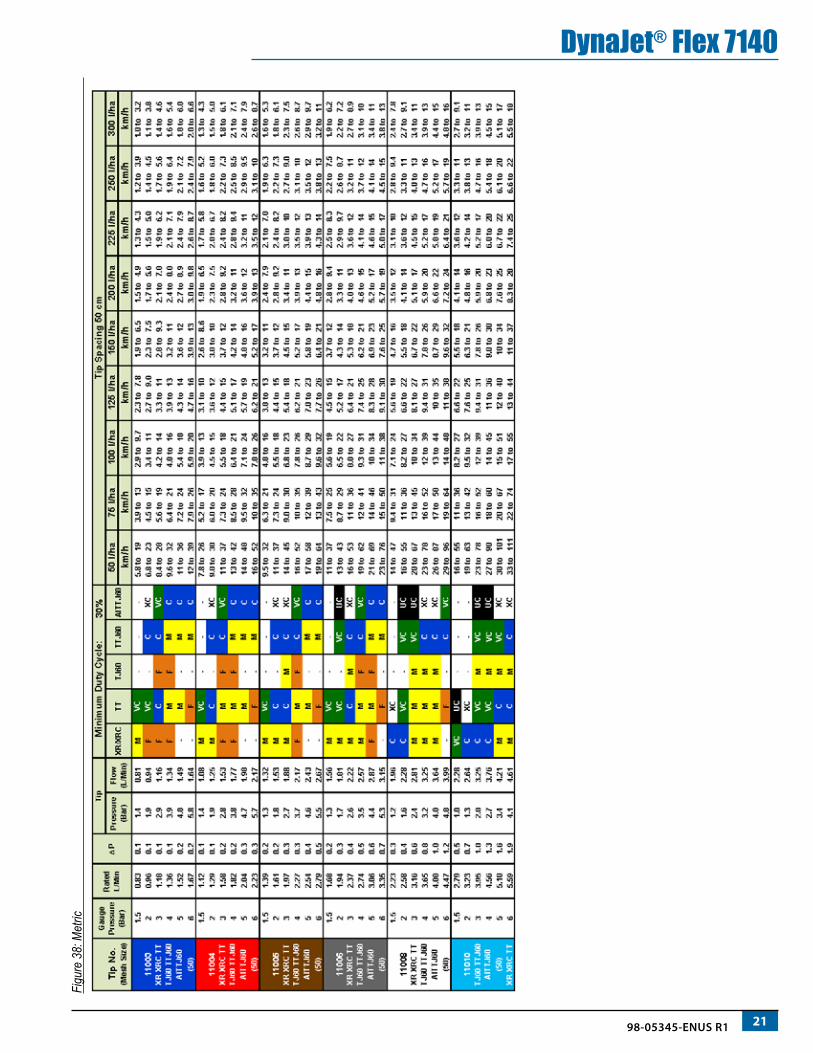
DynaJet® Flex 7140Nozzle Selection Example
These columns show flow rates at various pressures. The Delta P represents pressure loss through the DynaJet Flex solenoid valve, and the resulting Nozzle PSI and Flow show actual values at the spray nozzle.
These columns show droplet sizes for different styles of spray nozzle at given pressures. Use these columns to choose the best nozzle style for your application.
Just like a normal nozzle chart, these columns show rates available at given speeds. The only difference is the range of values that corresponds to the range of flows available with DynaJet Flex.
If the operator wants to apply 15 GPA at 10 MPH, he would look in the 10 MPH column, and find the row that shows 15 GPA with room above and below to compensate for higher and lower speeds that may be experienced in the field. In this case a TT11006 at 40-50 PSI will work very well.
The next consideration is droplet size. The chart shows that a Turbo TeeJet (TT) nozzle will give Very Coarse (VC) droplets in this pressure range, and a Turbo TwinJet (TTJ60) will give Coarse (C) droplets. The benefit of the TT is that the operator could select droplets from VC to M all at the same rate and speed.

16 www.teejet.com
DynaJet® Flex 7140TUNING DYNAJET FLEX®Tuning the Control Console ValveThe following procedure will help determine the rate controller valve gain that is the most aggressive value that will work over all pressure ranges with the DynaJet Flex in manual mode set to different duty cycles. The most aggressive value will be found by increasing the valve gains or other controller specific settings until system oscillates and then decrease those setting to make sure the system is stable at that value.
The tests will confirm that pulsing of flow through the solenoids doesn’t affect rate controller stability even when duty cycle is below 50%.
Ensure product pump is providing flow greater than the maximum demand of the system.
Adjust target application rate or machine speed to deliver minimum and maximum operating pressures for the nozzle in use under the following conditions (rate control must be operating in automatic mode for these tests):
1. DynaJet Flex duty cycle set to 100%.i. Set rate controller gains/values with operating pressure at minimum. Controller gain value at minimum pressure: _____________
ii. Set rate controller gains/values with operating pressure at maximum. Controller gain value at maximum pressure: _____________
2. DynaJet Flex duty cycle set to 50%.
i. Set rate controller gains/values with operating pressure at minimum. Controller gain value at minimum pressure: _____________
ii. Set rate controller gains/values with operating pressure at maximum. Controller gain value at maximum pressure: _____________
3. DynaJet Flex duty cycle set to “Minimum Duty Cycle” value (default is 30%)
i. Set rate controller gains/values with operating pressure at minimum. Controller gain value at minimum pressure: _____________
ii. Set rate controller gains/values with operating pressure at maximum. Controller gain value at maximum pressure: _____________
4. Set rate controller valve gain to the highest value that will work with all previous scenarios. This will be the lowest gain value found in the previous 6 tests. This value should not need to be changed again.
5. If the system does not control acceptably with this gain value at all manual duty cycle settings, then something is wrong with the system that needs to be resolved before trying to tune the DynaJet Flex System.
Tuning the DynaJet Flex SystemThe following steps will use Coarse Gain and Fine Gain to tune the DynaJet Flex System. Coarse Gain will be increased until the system is oscillating across the target pressure. Once that is occurring then Fine Gain will be increased to smooth/eliminate the oscillation. A Coarse Gain too low will cause the system to be stable but slow to get on target. A Coarse Gain too high will cause the system to overshoot target when a speed change happens. A Fine Gain too low will allow the system to continue to oscillate. A Fine Gain too high will cause the system to oscillate extremely rapidly and cause a thumping in the system. The lower the target pressure, the higher the Fine Gain can be set, so the tuning needs to be done at highest pressure/ smallest droplet size that the machine will typically be operating. Speed changes will be required for the best tuning possible. Simulated speed changes are preferred, but driving the machine is ok. Steady speeds are required.
1. Set console to Nozzle Mode and choose the nozzle being used.
2. Set Coarse Gain to 2 and Fine Gain to 2.
2.1 Disable Jump Point by setting value to 0.
2.2 Choose the highest pressure/smallest droplet size that will typically be used
2.3 Run the system and view the PSI on the DynaJet Flex when changing speed. Increase the Coarse Gain until system is oscillating across target pressure. Most machines operate with a setting between 4-6 for Coarse Gain.
3. Once Coarse Gain is determined, then using the same speed changes as before begin increasing Fine Gain until the oscillations stop and the target rate and target pressure are stable. Most machines operate with a setting between 8-12 for Fine Gain.
4. After Coarse Gain and Fine Gain have been set, then select a lower pressure/larger droplet size and run the machine using the same speed changes. Typically, the settings will not have to be changed for the lower pressure applications.
5. If more than one nozzle size is going to be used on the machine, then run a test with the same values for Coarse Gain and Fine Gain for the other nozzles. Always check at the highest pressure/smallest droplet size that will typically be used.
1798-05345-ENUS R1
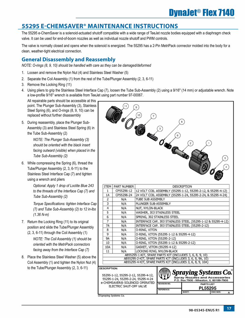
DynaJet® Flex 714055295 E-CHEMSAVER® MAINTENANCE INSTRUCTIONSThe 55295 e-ChemSaver is a solenoid-actuated shutoff compatible with a wide range of TeeJet nozzle bodies equipped with a diaphragm check valve. It can be used for end-of-boom nozzles as well as individual nozzle shutoff and PWM controls.
The valve is normally closed and opens when the solenoid is energized. The 55295 has a 2-Pin MetriPack connector molded into the body for a clean, weather-tight electrical connection.
General Disassembly and ReassemblyNOTE: O-rings (8, 9, 10) should be handled with care as they can be damaged/deformed
1. Loosen and remove the Nylon Nut (4) and Stainless Steel Washer (5)2. Separate the Coil Assembly (1) from the rest of the Tube/Plunger Assembly (2, 3, 6-11)3. Remove the Locking Ring (11)4. Using pliers to grip the Stainless Steel Interface Cap (7), loosen the Tube Sub-Assembly (2) using a 9/16″ (14 mm) or adjustable wrench. Note
a low-profile 9/16″ wrench is available from TeeJet using part number 97-00067.All repairable parts should be accessible at this point. The Plunger Sub-Assembly (3), Stainless Steel Spring (6), and O-rings (8, 9, 10) can be replaced without further disassembly
5. During reassembly, place the Plunger Sub-Assembly (3) and Stainless Steel Spring (6) in the Tube Sub-Assembly (2)
NOTE: The Plunger Sub-Assembly (3) should be oriented with the black insert facing outward (visible) when placed in the Tube Sub-Assembly (2)
6. While compressing the Spring (6), thread the Tube/Plunger Assembly (2, 3, 6-11) to the Stainless Steel Interface Cap (7) and tighten using a wrench and pliers
Optional: Apply 1 drop of Loctite Blue 243 to the threads of the Interface Cap (7) and Tube Sub-Assembly (2)
Torque Specifications: tighten Interface Cap (7) and Tube Sub-Assembly (2) to 12 in-lbs (1.36 N-m)
7. Return the Locking Ring (11) to its original position and slide the Tube/Plunger Assembly (2, 3, 6-11) through the Coil Assembly (1)
NOTE: The Coil Assembly (1) should be oriented with the MetriPack connectors facing away from the Interface Cap (7)
8. Place the Stainless Steel Washer (5) above the Coil Assembly (1) and tighten the Nylon Nut (4) to the Tube/Plunger Assembly (2, 3, 6-11)

18 www.teejet.com
DynaJet® Flex 7140A
PPLICATIO
N R
ATES AT GIV
EN SPEED
AN
D N
OZZLE C
APA
CITYFigure 35: US

1998-05345-ENUS R1
DynaJet® Flex 7140Fi
gure
36:
Met
ric

20 www.teejet.com
DynaJet® Flex 7140SPEED
RA
NG
E AVAILA
BLE AT G
IVEN
N N
OZZLE SIZE A
ND
APPLIC
ATION
RATE
Figure 37: US
2198-05345-ENUS R1
DynaJet® Flex 7140Fi
gure
38:
Met
ric

22 www.teejet.com
DynaJet® Flex 7140Figure 39: Dual Tip M
ode - US

2398-05345-ENUS R1
DynaJet® Flex 7140Fi
gure
40:
Dua
l Noz
zle M
ode
– M
etric

24 www.teejet.com
DynaJet® Flex 7140Figure 41: Dual Tip M
ode – US – Turf


DYNA JET® FLEX 7140INSTALLATION, SETUP AND USER GUIDE
www.teejet.com
An innovative new product from TeeJet makes spraying more efficient and more productive. The DynaJet Flex system uses a touch screen controller and individual solenoids to control each spray nozzle. This innovative system works along with an existing rate controller, and allows the operator to choose specific droplet sizes that will be used for a particular job. The rate controller manages application rate, and the DynaJet Flex system uses PWM technology to control system pressure and thereby control spray droplet size. Droplet size data is built into the controller so setup is easy and droplet sizes can be changed on the go. PWM control of each nozzle delivers very large ranges of speeds and application rates with a single spray nozzle and with consistent spray quality.
98-05345-ENUS-LT R1 English-US © TeeJet Technologies 2017
Copyrights© 2017 TeeJet Technologies. All rights reserved. No part of this document or the computer programs described in it may be reproduced, copied, photocopied, translated, or reduced in any form or by any means, electronic or machine readable, recording or otherwise, without prior written consent from TeeJet Technologies.
TrademarksUnless otherwise noted, all other brand or product names are trademarks or registered trademarks of their respective companies or organizations.
Limitation of LiabilityTEEJET TECHNOLOGIES PROVIDES THIS MATERIAL “AS IS” WITHOUT WARRANTY OF ANY KIND, EITHER EXPRESSED OR IMPLIED. NO COPYRIGHT LIABILITY OR PATENT IS ASSUMED. IN NO EVENT SHALL TEEJET TECHNOLOGIES BE LIABLE FOR ANY LOSS OF BUSINESS, LOSS OF PROFIT, LOSS OF USE OR DATA, INTERRUPTION OF BUSINESS, OR FOR INDIRECT, SPECIAL, INCIDENTAL, OR CONSEQUENTIAL DAMAGES OF ANY KIND, EVEN IF TEEJET TECHNOLOGIES HAS BEEN ADVISED OF SUCH DAMAGES ARISING FROM TEEJET TECHNOLOGIES SOFTWARE.