e 16-06 module 3a angular exp joints general boa ag · bending moments of angular expansion joints...
TRANSCRIPT
Expansion Joints Guide Module 3a - Angular Expansion Joints General - Standard Program (EFB) - Installation Instructions

2
Expansion Joints Guide Summary Module 3a 1 ANGULAR EXPANSION JOINTS GENERAL 3
1.1 Layout of hinge systems 4 1.2 Hinged expansion joint systems in general 5 1.3 Calculation of systems 6
1.3.1 Two pin I-system 6 1.3.2 Three pin I-system 8 1.3.3 Three pin L-system 9 1.3.4 Three pin U-system 11 1.3.5 Three pin Z1-system 12 1.3.6 Three pin Z2a-system 13 1.3.7 Three pin Z2b-system 14 1.3.8 Two pin gimbal I-system 16 1.3.9 Three pin gimbal L-system 18
2 STANDARD PROGRAM BOA ANGULAR EXPANSION JOINTS (EFB) 21
2.1 General 21 2.2 Reduction 21
2.2.1 Expansion capacity 21 2.2.2 Temperature related movement and pressure reduction 22
2.3 Angular expansion joints 22 2.3.1 Type AW (with weld ends) 22 2.3.2 Type AFS (with fixed flanges) 23 2.3.3 Type AFB (with flared flanges) 23 2.3.4 Type KAW (Gimbal expansion joint with weld ends) 23
3 INSTALLATION INSTRUCTIONS ANGULAR EXPANSION JOINTS 24
3.1 General safety recommendations 24 3.2 Angular expansion joints 25 3.3 Installation advice 26
BOA Expansion Joints Guide
15-11
Elastomer Formed Bellows (EFB):
• several to multi-ply (2 to 16 layers)
• high flexibility
• short construction length
• low displacement forces
• big movement capacity
• small corrugation height
• vibration absorbing

3
1 Angular Expansion Joints General The basic element of the angular (hinged) expansion joint is also the multi-ply bellows in austenitic steel. Contrary to axial expansion joints, the bellows of the angular expansion joint is not stressed in the direction of the tube axis, i.e. by elongation and compression, but is working in a lateral articulation. The hinge assembly attached outside the expansion joint absorbs not only the reaction force, but limits also the angular rotation. Depending on the desired deflection capacity of the bellows, it will be longer or shorter. Angular expansion joints are appropriate for the compensation of both long pipe sections of district heating systems as well as short boiler and turbine room pipelines in plane or three-dimensional pipe systems. If space is limited, the installation of a lateral or pressure balanced expan-sion joint should be considered. Contrary to axial and lateral expansion joints being independent compensating units, angular and gimbal expansion joints are only elements of an expansion system. A minimum of two and a maximum of three expansion joints form a statically defined system. Angular expansion joints are usually installed with 50% prerestraint. Preferably the prerestraint should be made on the already completed hinge system. While prerestraining, the pipeline’s installation temperature must be considered, especially pipelines above ground level. The prere-straint value may be taken from the prerestraint diagram. Angular expansion joints: distance The longer the distance L1 between two angular expansion joints is, the bigger the movement that can be compensated by the expansion system, and the smaller become the displacement forces. The rotation center of the hinges lies on the same axis as the bellows’ center (see fig. 1). Gimbal expansion joints utilize a round or square gimbal joint to take up the reaction forces. This enables three dimensional rotation around the X- and Z-axis (see fig. 2). Anchor points, pipe guide supports Angular expansion joints make no special demands on pipe supports or guides in contrast to axial expansion joints. Even swing hangers may be sufficient. Additional supports are unnecessary for short turbine house pipelines. The weight of the pipe legs between the angular expansion joints must be absorbed by appropriate hangers or supports in a way not to hinder the movement of the angular expansion joints. Appropriate pipe guides placed before and after each hinge system are necessary in long pipelines. Pipe guides having been fitted too tightly may become jammed. In a two-pin-system, pipe guides dimensioned with too little clearance may provoke deadlocks, which may jerkily free themselves leading to signif-icant additional loads. Hinged expansion joints in a two-pin-I-expansion system follow an arc due to their angular rotation (see fig. 3). The pipe guides should fulfil the following requirements:
• take up the weight of the pipeline and the expansion joints
• guide the expanding pipeline in its longitudinal axis
• provide sufficient clearance s to assure that pipe movements not compensated by expansion joints, resulting both from the thermal
expansion ∆L of the pipeline displacement L, and the arc height h, can be compensated by the continuing pipeline without causing the guide to jam.
Fig. 1
Fig. 2
s ≥ h + ∆L [mm]
BOA Expansion Joints Guide
4
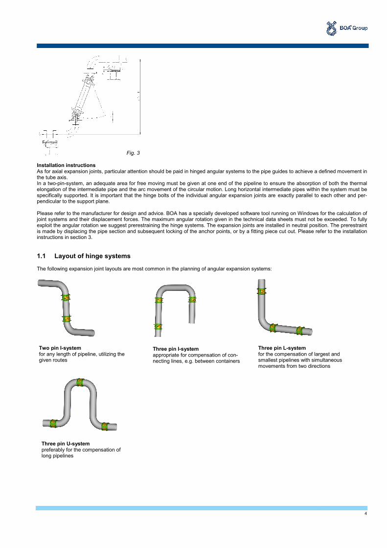
Installation instructions As for axial expansion joints, particular attention should be paid in hinged angular systems to the pipe guides to achieve a defined movement in the tube axis. In a two-pin-system, an adequate area for free moving must be given at one end of the pipeline to ensure the absorption of both the thermal elongation of the intermediate pipe and the arc movement of the circular motion. Long horizontal intermediate pipes within the system must be specifically supported. It is important that the hinge bolts of the individual angular expansion joints are exactly parallel to each other and per-pendicular to the support plane. Please refer to the manufacturer for design and advice. BOA has a specially developed software tool running on Windows for the calculation of joint systems and their displacement forces. The maximum angular rotation given in the technical data sheets must not be exceeded. To fully exploit the angular rotation we suggest prerestraining the hinge systems. The expansion joints are installed in neutral position. The prerestraint is made by displacing the pipe section and subsequent locking of the anchor points, or by a fitting piece cut out. Please refer to the installation instructions in section 3.
1.1 Layout of hinge systems The following expansion joint layouts are most common in the planning of angular expansion systems:
Fig. 3
Two pin I-system for any length of pipeline, utilizing the given routes
Three pin U-system preferably for the compensation of long pipelines
Three pin I-system appropriate for compensation of con-necting lines, e.g. between containers
Three pin L-system for the compensation of largest and smallest pipelines with simultaneous movements from two directions
5
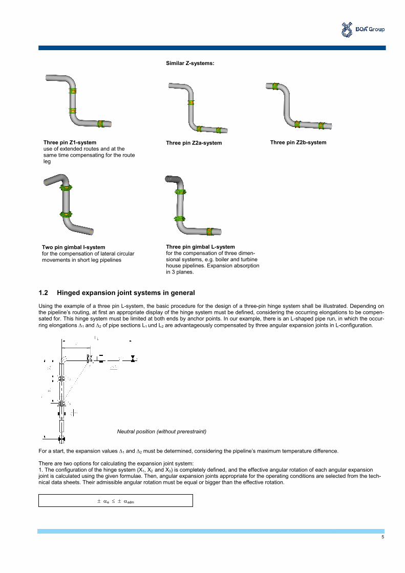
1.2 Hinged expansion joint systems in general Using the example of a three pin L-system, the basic procedure for the design of a three-pin hinge system shall be illustrated. Depending on the pipeline’s routing, at first an appropriate display of the hinge system must be defined, considering the occurring elongations to be compen-sated for. This hinge system must be limited at both ends by anchor points. In our example, there is an L-shaped pipe run, in which the occur-
ring elongations ∆1 and ∆2 of pipe sections L1 und L2 are advantageously compensated by three angular expansion joints in L-configuration.
For a start, the expansion values ∆1 and ∆2 must be determined, considering the pipeline’s maximum temperature difference. There are two options for calculating the expansion joint system: 1. The configuration of the hinge system (X1, X2 and X3) is completely defined, and the effective angular rotation of each angular expansion joint is calculated using the given formulae. Then, angular expansion joints appropriate for the operating conditions are selected from the tech-nical data sheets. Their admissible angular rotation must be equal or bigger than the effective rotation.
Three pin Z1-system use of extended routes and at the same time compensating for the route leg
Similar Z-systems:
Three pin Z2a-system Three pin Z2b-system
Three pin gimbal L-system for the compensation of three dimen-sional systems, e.g. boiler and turbine house pipelines. Expansion absorption in 3 planes.
Neutral position (without prerestraint)
± αe ≤ ± αadm
Two pin gimbal I-system for the compensation of lateral circular movements in short leg pipelines

6
2. After selecting the appropriate angular expansion joints, the required hinge distances X1 and X3 are calculated. It should be noted that the
nominal angular deflections ± α of the technical data sheets must be converted into admissible angular deflections ± αadm, according to section "Reduction", if the operating conditions exceed the rated conditions. In order to obtain the smallest possible bending angle of the expansion joints, the hinge distances X1 and X3 should be as large as possible and practicable, the distance X2 as small as possible. If applicable, the pipe elbow may be welded directly to the expansion joint. Thus, a straight piece of pipe is not necessary.
The calculation formulae for the bending angle of three-pin hinge systems are approximations sufficiently accurate for practical use. In almost plane systems, in which the intermediate joint approaches the prerestrained position of the stretched position (see fig. Installation position), a more accurate angle calculation is required. In such cases, please inquire.
In order to achieve optimum utilization of the admissible angular rotation ± αadm of hinged ex-pansion joints, a 50% pretrestraint of the system is required. If prerestraint is not possible, the angular rotation to one side of the center line doubles. Usually, this requires an angular expan-sion joint with a larger nominal angular rotation.
Anchor and nozzle loads can be determined using the calculation formulae for displacement forces F and bending moments M.
1.3 Calculation of systems 1.3.1 Two pin I-system Required hinge distance
With the admissible angular rotation αadm and 50% prerestraint, the minimum distance X1 between the hinges is:
± αadm = ± α ∙ K∆ (tB) ∙ KL
Operating position
Installation position (50% prerestrained)
7
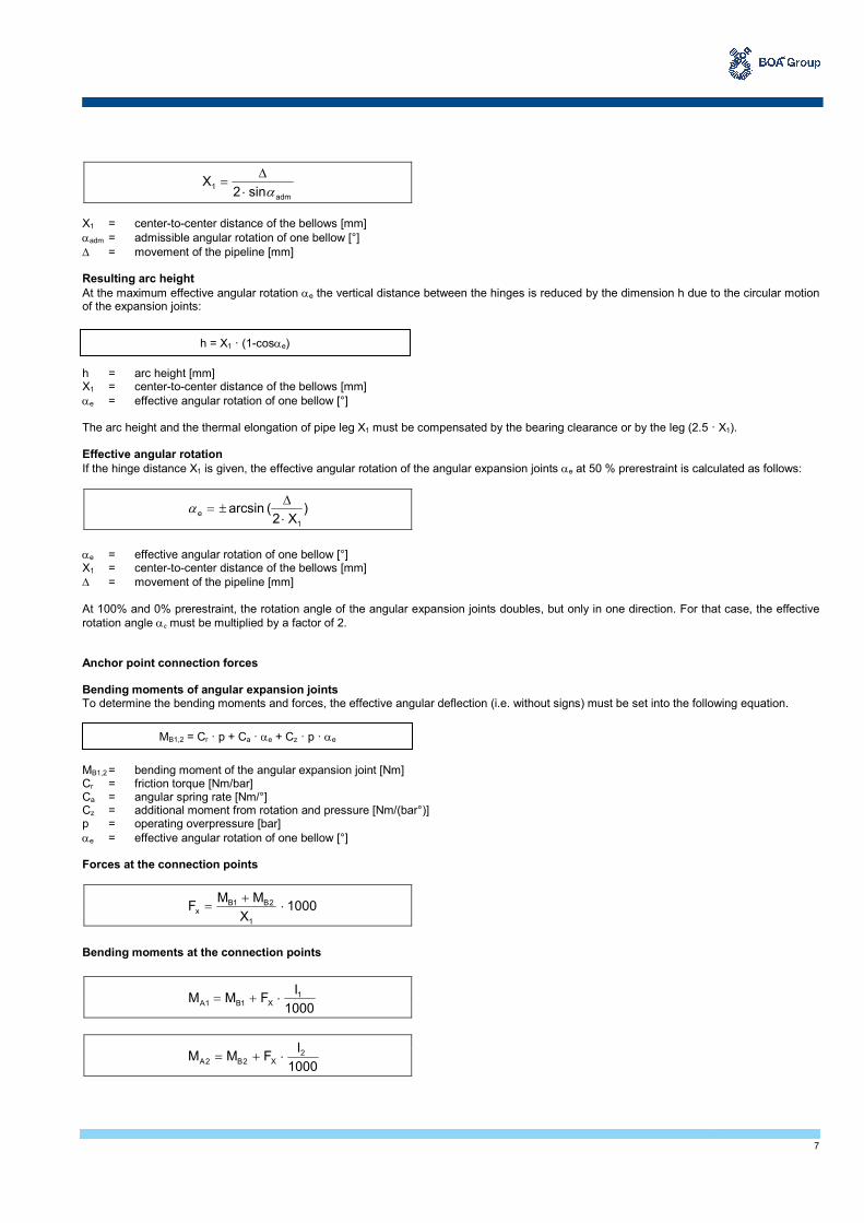
X1 = center-to-center distance of the bellows [mm]
αadm = admissible angular rotation of one bellow [°]
∆ = movement of the pipeline [mm] Resulting arc height
At the maximum effective angular rotation αe the vertical distance between the hinges is reduced by the dimension h due to the circular motion of the expansion joints: h = arc height [mm] X1 = center-to-center distance of the bellows [mm]
αe = effective angular rotation of one bellow [°] The arc height and the thermal elongation of pipe leg X1 must be compensated by the bearing clearance or by the leg (2.5 · X1). Effective angular rotation
If the hinge distance X1 is given, the effective angular rotation of the angular expansion joints αe at 50 % prerestraint is calculated as follows:
αe = effective angular rotation of one bellow [°] X1 = center-to-center distance of the bellows [mm]
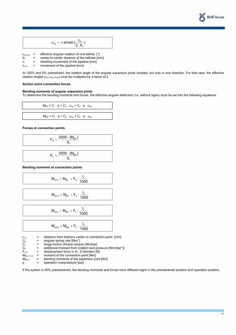
∆ = movement of the pipeline [mm] At 100% and 0% prerestraint, the rotation angle of the angular expansion joints doubles, but only in one direction. For that case, the effective
rotation angle αe must be multiplied by a factor of 2. Anchor point connection forces Bending moments of angular expansion joints To determine the bending moments and forces, the effective angular deflection (i.e. without signs) must be set into the following equation. MB1,2 = bending moment of the angular expansion joint [Nm] Cr = friction torque [Nm/bar] Ca = angular spring rate [Nm/°] Cz = additional moment from rotation and pressure [Nm/(bar°)] p = operating overpressure [bar]
αe = effective angular rotation of one bellow [°] Forces at the connection points
Bending moments at the connection points
adm
1sin2
Xα⋅
∆=
h = X1 · (1-cosαe)
)X2
(arcsin1
e⋅
∆±=α
MB1,2 = Cr · p + Ca · αe + Cz · p · αe
1000X
MMF
1
2B1Bx ⋅
+=
1000
IFMM 1
X1B1A ⋅+=
1000
IFMM 2
X2B2A ⋅+=
8
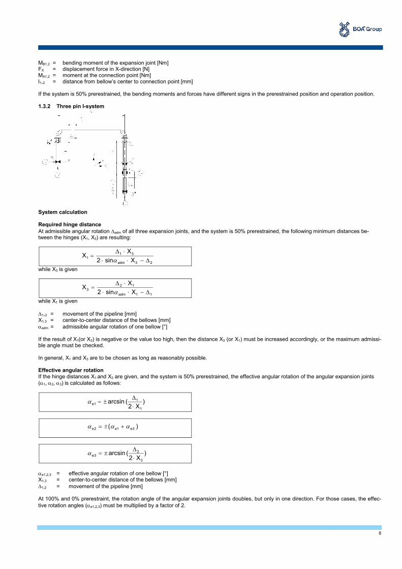
MB1,2 = bending moment of the expansion joint [Nm] FX = displacement force in X-direction [N] MA1,2 = moment at the connection point [Nm] l1,2 = distance from bellow’s center to connection point [mm] If the system is 50% prerestrained, the bending moments and forces have different signs in the prerestrained position and operation position. 1.3.2 Three pin I-system System calculation Required hinge distance
At admissible angular rotation ∆adm of all three expansion joints, and the system is 50% prerestrained, the following minimum distances be-tween the hinges (X1, X3) are resulting:
while X3 is given
while X1 is given
∆1,2 = movement of the pipeline [mm] X1,3 = center-to-center distance of the bellows [mm]
αadm = admissible angular rotation of one bellow [°] If the result of X1(or X3) is negative or the value too high, then the distance X3 (or X1) must be increased accordingly, or the maximum admissi-ble angle must be checked. In general, X1 and X3 are to be chosen as long as reasonably possible. Effective angular rotation If the hinge distances X1 and X3 are given, and the system is 50% prerestrained, the effective angular rotation of the angular expansion joints
(α1, α2, α3) is calculated as follows:
αe1,2,3 = effective angular rotation of one bellow [°] X1,3 = center-to-center distance of the bellows [mm]
∆1,2 = movement of the pipeline [mm] At 100% and 0% prerestraint, the rotation angle of the angular expansion joints doubles, but only in one direction. For those cases, the effec-
tive rotation angles (αe1,2,3) must be multiplied by a factor of 2.
23adm
311
Xsin2
XX
∆−⋅⋅
⋅∆=
α
11adm
123
Xsin2
XX
∆−⋅⋅
⋅∆=
α
)X2
(arcsin1
11e
⋅
∆±=α
)( 3e1e2e ααα +±=
)X2
(arcsin3
23e
⋅
∆±=α

9
Anchor point connection forces Bending moments of angular expansion joints To determine the bending moments and forces, the effective angular deflection (i.e. without signs) must be set into the following equations. MB1,2,3 = bending moment of the expansion joint [Nm] Cr = friction torque [Nm/bar] Ca = angular spring rate [Nm/°] Cz = additional moment from rotation and pressure [Nm/(bar°)] p = operating overpressure [bar]
αe1,2,3 = effective angular rotation of one bellow [°] Forces at the connection points
Bending moments at the connection points
MB1,2,3 = bending moment of the expansion joint [Nm] FX,Z = displacement force in X-, Z-direction [N] MA1,2 = moment at the connection point [Nm] l1,2 = distance from bellow’s center to connection point [mm] If the system is 50% prerestrained, the bending moments and forces have different signs in the prerestrained position and operation position. 1.3.3 Three pin L-system
MB1 = Cr · p + Ca · αe1 + Cz · p · αe1
MB2 = Cr · p + Ca · αe2 + Cz · p · αe2
MB3 = Cr · p + Ca · αe3 + Cz · p · αe3
1000X
MMF
3
3B2BX ⋅
+=
1000X
MMF
1
2B1BZ ⋅
+=
1000
IFMM 1
X1B1A ⋅+=
1000
IFMM 2
X3B2A ⋅+=

10
Required hinge distance
At admissible angular rotation αadm of all three expansion joints, and the system is 50% prerestrained, the following minimum distances be-tween the hinges (X1, X3) are resulting:
while X2 and X3 are given
while X1 and X2 are given
∆1,2 = movement of the pipeline [mm] X1,2,3 = center-to-center distance of the bellows [mm]
αadm = admissible angular rotation of one bellow [°] If the result of X1 (or X3) is negative or the value too high, then the distance X3 (or X1) must be increased accordingly, or the maximum admissi-ble angle must be checked. In general, X1 and X3 are to be chosen as long as reasonably possible, whereas X2 as small as possible. Effective angular rotation If the hinge distances X1 and X3 are given, and the system is 50% prerestrained, the effective angular rotation of the angular expansion joints
(α1, α2, α3) is calculated as follows:
αe1,2,3 = effective angular rotation of one bellow [°] X1,,2,3 = center-to-center distance of the bellows [mm]
∆1,2 = movement of the pipeline [mm] At 100% and 0% prerestraint, the rotation angle of the angular expansion joints doubles, but only in one direction. For those cases, the effec-
tive rotation angles (αe1,2,3) must be multiplied by a factor of 2. Anchor point connection forces Bending moments of angular expansion joints To determine the bending moments and forces, the effective angular deflection (i.e. without signs) must be set into the following equations. MB1,2,3 = bending moment of the expansion joint [Nm] Cr = friction torque [Nm/bar] Ca = angular spring rate [Nm/°] Cz = additional moment from rotation and pressure [Nm/(bar°)] p = operating overpressure [bar] αe1,2,3 = effective angular rotation of one bellow [°] Forces at the connection points
23adm
2311
Xsin2
)XX(X
∆−⋅⋅
+⋅∆=
α
11adm
21123
Xsin2
)XXX
∆−⋅⋅
⋅∆+⋅∆=
α
)X2
(arcsin1
11e
⋅
∆±=α
)( 3e1e2e ααα +±=
)XX2
XX(arcsin
31
21123e
⋅⋅
⋅∆+⋅∆±=α
MB1 = Cr · p + Ca · αe1 + Cz · p · αe1
MB2 = Cr · p + Ca · αe2 + Cz · p · αe2
MB3 = Cr · p + Ca · αe3 + Cz · p · αe3
1
2Z2B1BX
X
1000)
1000
XFMM(F ⋅⋅++=
11
Bending moments at the connection points
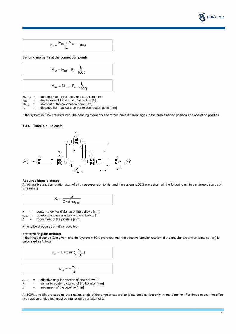
MB1,2,3 = bending moment of the expansion joint [Nm] FX,Z = displacement force in X-, Z-direction [N] MA1,2 = moment at the connection point [Nm] l1,2 = distance from bellow’s center to connection point [mm] If the system is 50% prerestrained, the bending moments and forces have different signs in the prerestrained position and operation position. 1.3.4 Three pin U-system Required hinge distance
At admissible angular rotation ∆adm of all three expansion joints, and the system is 50% prerestrained, the following minimum hinge distance X1 is resulting:
X1 = center-to-center distance of the bellows [mm]
αadm = admissible angular rotation of one bellow [°]
∆ = movement of the pipeline [mm] X2 is to be chosen as small as possible. Effective angular rotation
If the hinge distance X1 is given, and the system is 50% prerestrained, the effective angular rotation of the angular expansion joints (α1, α2) is calculated as follows:
αe1,2, = effective angular rotation of one bellow [°] X1 = center-to-center distance of the bellows [mm]
∆ = movement of the pipeline [mm] At 100% and 0% prerestraint, the rotation angle of the angular expansion joints doubles, but only in one direction. For those cases, the effec-
tive rotation angles (αe) must be multiplied by a factor of 2.
1000X
MMF
3
3B2BZ ⋅
+=
1000
IFMM 1
Z1B1A ⋅+=
1000
IFMM 2
X3B2A ⋅+=
adm
1sin2
Xα⋅
∆=
)X2
(arcsin1
11e
⋅
∆±=α
2
1e2e
αα ±=

12
Anchor point connection forces Bending moments of angular expansion joints To determine the bending moments and forces, the effective angular deflection (i.e. without signs) must be set into the following equations. MB1,2 = bending moments of the expansion joint [Nm] Cr = friction torque [Nm/bar] Ca = angular spring rate [Nm/°] Cz = additional moment from rotation and pressure [Nm/(bar°)] p = operation overpressure [bar] αe1,2 = effective angular rotation of one bellow [°] Forces at connection points
Bending moments at connection points MB1,2 = bending moments of the expansion joint [Nm] MA = moment at the connection point [Nm] FX = displacement force in X-direction [N] X1 = center-to-center distance of the bellows [mm] If the system is 50% prerestrained, the bending moments and forces have different signs in the prerestrained position and operation position. 1.3.5 Three pin Z1-system Required hinge distances and effective angular rotation The layout of the expansion joints is the same as for the three pin L-system, but with an additional leg. The calculation formulae of the required hinge distances and the effective angular rotation may be taken from section 1.3.3 "Three pin L-system". Anchor point connection forces Bending moments of angular expansion joints To determine the bending moments and forces, the effective angular deflection (i.e. without signs) must be set into the following equations.
MB1 = Cr · p + Ca · αe1 + Cz · p · αe1
MB2 = Cr · p + Ca · αe2 + Cz · p · αe2
1000X
MMF
1
2B1BX ⋅
+=
MA = MB2
MB1 = Cr · p + Ca · αe1 + Cz · p · αe1
MB2 = Cr · p + Ca · αe2 + Cz · p · αe2
MB3 = Cr · p + Ca · αe3 + Cz · p · αe3

13
MB1,2,3 = bending moments of the expansion joint [Nm] Cr = friction torque [Nm/bar] Ca = angular spring rate [Nm/°] Cz = additional moment from rotation and pressure [Nm/(bar°)] p = operation overpressure [bar] αe1,2,3 = effective angular rotation of one bellow [°] Forces at connection points
Bending moments at connection points
MB1,2,3 = bending moments of the expansion joint [Nm] FX,Z = displacement force in X-, Z-direction [N] MA1,2 = moment at the connection point [Nm] l1,2 = distance from bellow’s center to connection point [mm] If the system is 50% prerestrained, the bending moments and forces have different signs in the prerestrained position and operation position. 1.3.6 Three pin Z2a-system Required hinge distances and effective angular rotation The layout of the expansion joints is the same as for the three pin L-system, but with an additional leg. The calculation formulae of the required hinge distances and the effective angular rotation may be taken from section 1.3.3 "Three pin L-system". Anchor point connection forces Bending moments of angular expansion joints To determine the bending moments and forces, the effective angular deflection (i.e. without signs) must be set into the following equations.
1000)XX
X)MM(
X
MM(F
3
23B2B
1
2B1BZ
1
⋅⋅
⋅++
+=
1000X
MMF
3
3B2BX ⋅
+=
1000
IFMM 1
Z1B2A ⋅+=
1000
IF
1000
IFMM 3
Z2
X3B2A ⋅−⋅+=
MB1 = Cr · p + Ca · αe1 + Cz · p · αe1
MB2 = Cr · p + Ca · αe2 + Cz · p · αe2
MB3 = Cr · p + Ca · αe3 + Cz · p · αe3

14
MB1,2,3 = bending moments of the expansion joint [Nm] Cr = friction torque [Nm/bar] Ca = angular spring rate [Nm/°] Cz = additional moment from rotation and pressure [Nm/(bar°)] p = operation overpressure [bar] αe1,2,3 = effective angular rotation of one bellow [°] Forces at connection points
Bending moments at connection points
MB1,2,3 = bending moments of the expansion joint [Nm] FX,Z = displacement force in X- bzw. Z-direction [N] MA1,2 = moment at the connection point [Nm] l1,2 = distance from bellow’s center to connection point [mm] If the system is 50% prerestrained, the bending moments and forces have different signs in the prerestrained position and operation position. 1.3.7 Three pin Z2b-system Required hinge distances
At admissible angular rotation ∆adm of all three expansion joints, and the system is 50% prerestrained, the following minimum hinge distances X1 and X3 are resulting:
while X2 and X3 are given
while X1 and X2 are given
X1,2,3 = center-to-center distance of the bellows [mm]
∆1,2 = movement of the pipeline [mm]
αzul = admissible angular rotation of one bellow [°]
1000)XX
X)MM(
X
MM(F
3
23B2B
1
2B1BZ
1
⋅⋅
⋅++
+=
1000X
MMF
3
3B2BX ⋅
+=
1000
IF
1000
IFMM 0
X1
Z1B1A ⋅−⋅+=
1000
IFMM 2
X3B2A ⋅+=
23adm
31211
4Xsin8
)X4X8(X
∆⋅−⋅⋅
⋅+∆+⋅⋅∆=
α
11adm
211213
4Xsin8
X4)X8(X
∆⋅−⋅⋅
∆⋅⋅+∆+⋅⋅∆=
α
15
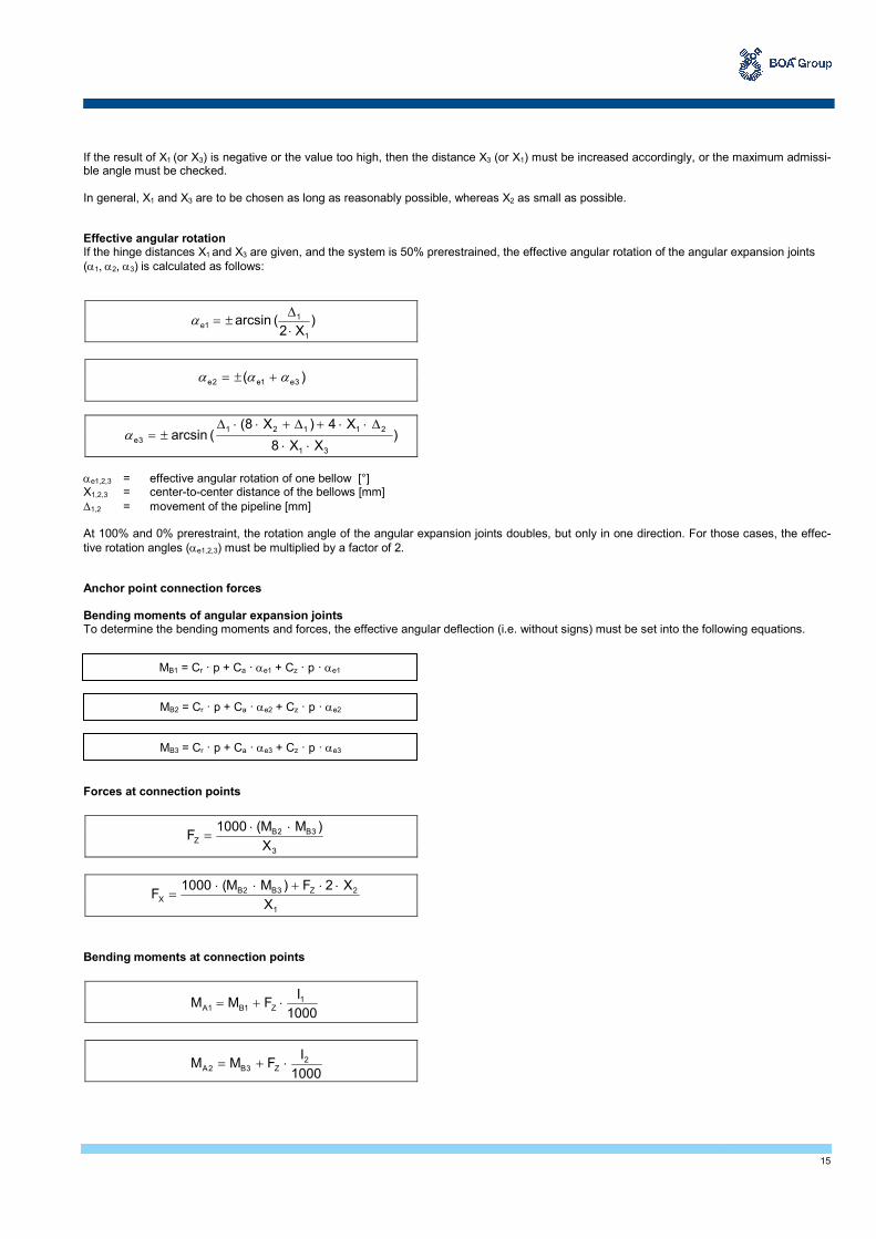
If the result of X1 (or X3) is negative or the value too high, then the distance X3 (or X1) must be increased accordingly, or the maximum admissi-ble angle must be checked. In general, X1 and X3 are to be chosen as long as reasonably possible, whereas X2 as small as possible. Effective angular rotation If the hinge distances X1 and X3 are given, and the system is 50% prerestrained, the effective angular rotation of the angular expansion joints
(α1, α2, α3) is calculated as follows:
αe1,2,3 = effective angular rotation of one bellow [°] X1,2,3 = center-to-center distance of the bellows [mm]
∆1,2 = movement of the pipeline [mm] At 100% and 0% prerestraint, the rotation angle of the angular expansion joints doubles, but only in one direction. For those cases, the effec-
tive rotation angles (αe1,2,3) must be multiplied by a factor of 2. Anchor point connection forces Bending moments of angular expansion joints To determine the bending moments and forces, the effective angular deflection (i.e. without signs) must be set into the following equations. Forces at connection points
Bending moments at connection points
)X2
(arcsin1
11e
⋅
∆±=α
)( 3e1e2e ααα +±=
)XX8
X4)X8((arcsin
31
21121
3e⋅⋅
∆⋅⋅+∆+⋅⋅∆±=α
MB1 = Cr · p + Ca · αe1 + Cz · p · αe1
MB2 = Cr · p + Ca · αe2 + Cz · p · αe2
MB3 = Cr · p + Ca · αe3 + Cz · p · αe3
3
3B2BZ
X
)MM(1000F
⋅⋅=
1000
IFMM 1
Z1B1A ⋅+=
1000
IFMM 2
Z3B2A ⋅+=
1
2Z3B2BX
X
X2F)MM(1000F
⋅⋅+⋅⋅=
16
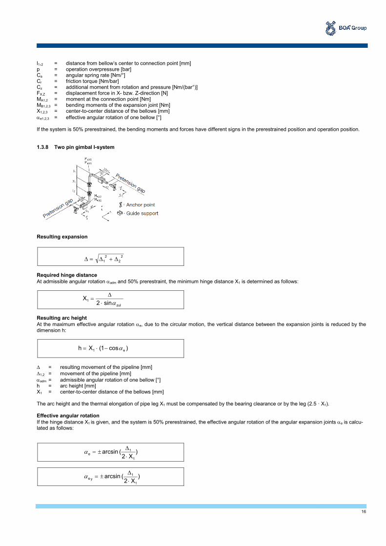
l1,2 = distance from bellow’s center to connection point [mm] p = operation overpressure [bar] Ca = angular spring rate [Nm/°] Cr = friction torque [Nm/bar] Cz = additional moment from rotation and pressure [Nm/(bar°)] FX,Z = displacement force in X- bzw. Z-direction [N] MA1,2 = moment at the connection point [Nm] MB1,2,3 = bending moments of the expansion joint [Nm] X1,2,3 = center-to-center distance of the bellows [mm]
αe1,2,3 = effective angular rotation of one bellow [°] If the system is 50% prerestrained, the bending moments and forces have different signs in the prerestrained position and operation position. 1.3.8 Two pin gimbal I-system Resulting expansion
Required hinge distance
At admissible angular rotation αadm and 50% prerestraint, the minimum hinge distance X1 is determined as follows:
Resulting arc height
At the maximum effective angular rotation αe, due to the circular motion, the vertical distance between the expansion joints is reduced by the dimension h:
∆ = resulting movement of the pipeline [mm]
∆1,2 = movement of the pipeline [mm]
αadm = admissible angular rotation of one bellow [°] h = arc height [mm] X1 = center-to-center distance of the bellows [mm] The arc height and the thermal elongation of pipe leg X1 must be compensated by the bearing clearance or by the leg (2.5 · X1). Effective angular rotation
If the hinge distance X1 is given, and the system is 50% prerestrained, the effective angular rotation of the angular expansion joints αe is calcu-lated as follows:
2
2
2
1 ∆+∆=∆
zul
1sin2
Xα⋅
∆=
)cos1(Xh e1 α−⋅=
)X2
(arcsin1
1e
⋅
∆±=α
)X2
(arcsin1
1
ye⋅
∆±=α
17
αex,,ey = effective angular rotation of one bellow [°] X1 = center-to-center distance of the bellows [mm]
∆ = resulting movement of the pipeline [mm]
∆1,2 = movement of the pipeline [mm] At 100% and 0% prerestraint, the rotation angle of the angular expansion joints doubles, but only in one direction. For that case, the effective
rotation angles (αe, αex, αey) must be multiplied by a factor of 2. Anchor point connection forces Bending moments of angular expansion joints To determine the bending moments and forces, the effective angular deflection (i.e. without signs) must be set into the following equations.
Forces at connection points
Bending moments at connection points
l1,2 = distance from bellow’s center to connection point [mm] Ca = angular spring rate [Nm/°] Cr = hinge friction (friction torque) [Nm/bar] Cz = additional moment from rotation and pressure [Nm/(bar°)] FX,Z = displacement force in X-, Z-direction [N] MAX, Y1,2 = moment at the connection point [Nm] MBX,Y = bending moments of the expansion joint [Nm] p = operation overpressure [bar] If the system is 50% prerestrained, the bending moments and forces have different signs in the prerestrained position and operation position.
)X2
(arcsin1
2ex
⋅
∆±=α
MBY = Cr · p + Ca · αey + Cz · p · αey
MBX = Cr · p + Ca · αex + Cz · p · αex
1
BYX
X
)M(2000F
⋅=
1
BXY
X
)M(2000F
⋅=
1000
IFMM 1
XBY1AY ⋅+=
1000
IFMM 2
XBY2AY ⋅+=
1000
IFMM 1
YBX1AX ⋅+=
1000
IFMM 2
YBX2AX ⋅+=

18
1.3.9 Three pin gimbal L-system W1 = 1 angular expansion joint (angular rotation in one plane) W2,3 = 1 gimbal expansion joint each (angular rotation in a circular plane)
The expansion of the equipment nozzle or connecting neck must be added to the expansion of the pipe legs ∆1, ∆2, or ∆3, if both move in the same direction, and must be subtracted if they move in opposite directions. Effective angular rotation If the hinge distances X1 and X3 are given, and the system is 50% prerestrained, the effective angular rotation of the angular expansion joints
(α1, α2, α3) is calculated as follows:
X1,2,3 = center-to-center distance of the bellows [mm]
αe1,2,3,x,,y = effective angular rotation of one bellow [°]
∆1,2,3 = movement of the pipeline [mm] At 100% and 0% prerestraint, the rotation angle of the angular expansion joints doubles, but only in one direction. For that case, the effective
rotation angles αe1,2,3,x,,y must be multiplied by a factor of 2. In general, X1 and X3 are to be chosen as long as reasonably possible, whereas X2 as small as possible.
)X2
(arcsin1
1
1e⋅
∆±=α
)( y3e1e1e ααα +±=
)XX2
XX(arcsin
31
1221y3e
⋅⋅
⋅∆+⋅∆±=α
)X2
(arcsin3
3y3ex2e
⋅
∆±== αα
)(2
y2e
2
x2e2e ααα +±=
)(2
y3e
2
x3e3e ααα +±=

19
Anchor point connection forces Bending moments of angular expansion joints To determine the bending moments and forces, the effective angular deflection (i.e. without signs) must be set into the following equations. Forces at connection points
Bending moments at connection points
MB1Y = Cr · p + Ca · αe1 + Cz · p · αe1
MB2Y = Cr · p + Ca · αe2y + Cz · p · αe2y
MB3Y = Cr · p + Ca · αe3y + Cz · p · αe3y
MB2X = Cr · p + Ca · αe2x + Cz · p · αe2x
MB3X = Cr · p + Ca · αe3x + Cz · p · αe3x
3
Y3BY2BX
X
)MM(1000F
+⋅=
3
X3BX2BY
X
)MM(1000F
+⋅=
1000
XFMM 2
XY2B0 ⋅+=
1
0Y1BZ
X
)MM(1000F
+⋅=
1000
IFMM 1
ZY1B1AY ⋅−−=
1000
IFMM 2
XY3B2AY ⋅+=
1000
XFMM 2
YX2B1AX ⋅−−=
1000
IF
1000
IFMM 3
Z2
YX3B2AX ⋅+⋅−−=
1000
IXFM 11
Y1AZ
+⋅=
1000
IFM 3
X2AZ ⋅−=

20
l1,2,3 = distance from bellow’s center to connection point [mm] Ca = angular spring rate [Nm/°] Cr = hinge friction (friction torque) [Nm/bar] Cz = additional moment from rotation and pressure [Nm/(bar°)] FX,Y,Z = displacement force in X-, Y-, Z-direction [N] MAX,Y,Z1,2 = moment at the connection point [Nm] MB1,2,3,X,Y = bending moments of the expansion joint [Nm] p = operation overpressure [bar] If the system is 50% prerestrained, the bending moments and forces have different signs in the prerestrained position and operation position.
21
2 Standard Program BOA Angular Expansion Joints (EFB)
2.1 General Expansion joints manufactured by BOA AG Switzerland are formed in the elastomer process (EFB). The core element is the multi-ply metal bellows (2 to 16 layers) made of austenitic steel. Expansion joints produced by this method have a large expansion capacity and are very flexible. They are especially appropriate to compensate for thermal expansion and minor misalignment during installation. Their advantages are:
• BOA AG has over 70 years experience in manufacturing expansion joints
• multi-ply construction of the bellows, made of high-grade stainless steel (1.4571 and 1.4541), which means high resistance against ageing, temperature, UV-rays and most of aggressive media.
• very low spring rate due to the multi-ply construction of the bellows.
• large movements at short construction lengths
• due to reasonable stocks, various types in different sizes and pressure ranges are usually available at short time. Inner sleeve Inner sleeves protect the bellows and prevent it from being stimulated to oscillate by the fluid. The installation of an inner sleeve is recommend-ed in the following cases:
• abrasive media
• large temperature variations
• flow rates higher than approx. 8m/s for gaseous media
• flow rates higher than approx. 3m/s for liquid media When installing, the flow direction must be observed! The designation for the design with/without inner sleeve for angular expansion joints (type AW) and gimbal expansion joints (KAW) is the following: Expansion joint types marked with* are available either with or without inner sleeve (extra charge for inner sleeve). Expansion joint types marked "B" do not need an inner sleeve because of their short length. Expansion joint types marked "L" have always an inner sleeve. Example: Type AW16-3B = Basic version without inner sleeve Type AW16-3L = Basic version with inner sleeve Type AW16-2* = Basic version without inner sleeve, but may be equipped with inner sleeve.
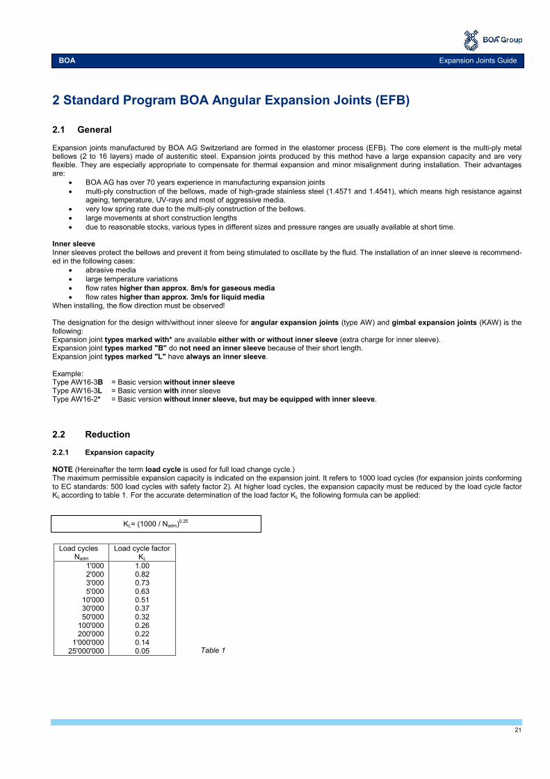
2.2 Reduction 2.2.1 Expansion capacity NOTE (Hereinafter the term load cycle is used for full load change cycle.) The maximum permissible expansion capacity is indicated on the expansion joint. It refers to 1000 load cycles (for expansion joints conforming to EC standards: 500 load cycles with safety factor 2). At higher load cycles, the expansion capacity must be reduced by the load cycle factor KL according to table 1. For the accurate determination of the load factor KL the following formula can be applied:
BOA Expansion Joints Guide
KL= (1000 / Nadm)0.29
Load cycles Nadm
Load cycle factor KL
1'000 2'000 3'000 5'000
10'000 30'000 50'000
100'000 200'000
1'000'000 25'000'000
1.00 0.82 0.73 0.63 0.51 0.37 0.32 0.26 0.22 0.14 0.05
Table 1

22
2.2.2 Temperature related movement and pressure reduction NOTE The admissible operating pressure is determined by the nominal pressure considering the reduction factor KP according to tab. 2. At higher
temperatures, the expansion capacity K∆ has to be reduced according to the reduction factors.
1) linear interpolation for intermediate values
2.3 Angular expansion joints 2.3.1 Type AW (with weld ends)
• As a standard, expansion joints of type AW are manufactured in nominal diameters from DN 40 to DN 1000 mm and in pressure ranges of PN 16, 25 and 40. For PN 6 and 10, standard designs from DN 350 to DN 1000 are available.
• In type designation, PN is extended by the figure 1, 2, 3 and 4, depending on the construction dimension. AW 6-1 means e.g.: shortest expansion joint for pressure range PN 6; AW 25-4 means: the longest expansion joint for pressure range PN 25.
• As a standard, weld ends and tie rods are made of carbon steel and are primer coated.
• As special designs, also angular expansion joints type AFS (with fixed flanges) and of type AFB (with flared flanges) are manufac-tured.
• The design type I or II is indicated in the last column of the standard tables (see fig.). Design I Design II Available only without inner sleeve Optionally available with or without inner sleeve
Reduction factors 1) for pressure [KP]
and expansion capacity [K∆]
Temperature °C KP K∆
-10...20 50 100 150
1.00 0.92 0.87 0.83
1.00 0.97 0.94 0.92
200 250
0.79 0.74
0.90 0.88
300 350 400
0.67 0.60 0.53
0.86 0.85 0.84
Table 2

23
2.3.2 Type AFS (with fixed flanges)
• AFS are angular expansion joints with a raised face. The bellows and flanges are welded tightly together. The nominal expansion ca-pacity is either ±15 or 10°.
• As a standard, expansion joints of type AFS are manufactured in nominal diameters from DN 40 to DN 600 mm and in pressure ranges of PN 16 and 25.
• In type designation, PN 16 or 25 is extended by the figure 1, 2, 3 and 4, depending on the construction dimension. AFS 16-1 e.g. means: shortest expansion joint for pressure range PN 16, AFS 25-3: longer expansion joint for pressure range PN 25.
2.3.3 Type AFB (with flared flanges)
• AFB are angular expansion joints with a flared flange. The nominal expansion capacity is ±15° or less for larger DN types.
• As a standard, AFB expansion joints are manufactured in nominal diameters from DN 40 to DN 300 mm and in pressure ranges of PN 6 and 10.
• In type designation, PN 6 or 10 is not extended by a figure indicating the construction dimension. 2.3.4 Type KAW (Gimbal expansion joint with weld ends)
• As a standard, KAW expansion joints are manufactured in nominal diameters from DN 40 to DN 1000 mm and in pressure ranges of PN 6, 10, 16, 25 and 40.
• As a standard, weld ends and tie rods are made of carbon steel and are primer coated.
• As special designs, also gimbal expansion joints with fixed flanges or with flared flanges may be manufactured. Design I Design II Available only without inner sleeve Optionally available with or without inner sleeve

24
3 Installation Instructions Angular Expansion Joints 3.1 General safety recommendations Prior to installation and start-up, installation and start-up instructions must be read and observed. Installation, start-up and maintenance work shall only be performed by qualified and authorized staff. Maintenance Angular and gimbal expansion joints are maintenance free. CAUTION Prior to disassembly and maintenance, the system must be
• depressurized,
• cooled down,
• emptied.
Otherwise there is a risk of accident! Transport, packaging and storage
• The consignment must be checked for completeness upon receipt.
• Any transport damage must be reported to the carrier and the manufacturer.
• At an intermediate storage we recommend to use the original packaging. Admissible ambient conditions for storage and transport:
• ambient temperature - 4°C to +70 °C
• relative humidity up to 95%. Angular and gimbal expansion joints must be protected against wetness, humidity, dirt, shocks and damage. Warranty A warranty claim requires professional installation and start-up in accordance with installation and start-up instructions. The necessary installa-tion, start-up and maintenance work must be performed by qualified and authorized staff. Operating pressure NOTE
• The permissible operating pressure results in the nominal pressure considering the reduction factors given in section 2.2 "Reduction".
• At higher temperatures, the expansion capacity has to be reduced according to the reduction factors (see section 2.2). Start-up and check Before starting-up check if
• the pipeline is installed with sufficient inclination to avoid water pockets
• there is sufficient drainage
• pipe anchors and pipe supports/ guides are firmly installed prior to filling and pressure testing the system
• the expansion joint is not stressed by torsion, especially not expansion joints with socket attachment
• the flow direction has been observed for expansion joints with inner sleeves
• the steel bellows is free of dirt, welding, plaster or mortar splatters or any other soiling; clean if necessary
• all screwed connections are tightened properly
• the general due diligence requirements to avoid corrosion damage are observed, such as water treatment, or prevention of galvanic corrosion in copper and galvanized pipes.
Insulation Expansion joints may be insulated exactly as the pipeline.
• If no coating is provided, protect the bellows by means of a slidable metal sleeve to avoid insulation material dropping into the convolu-tions.
• If the expansion joint is to be placed under plaster, a protective cover is essential. This ensures the bellows’ function, protects against soiling and avoids contact with structure materials.
. Improper operation
• The limits given in the technical data of the standard range must not be exceeded.
• Swinging suspensions adjacent to expansion joints are not permitted.
• Do not clean the newly installed pipeline by blowing it with steam to avoid water hammers and unacceptable vibration stimulating of the bellows.
System start-up CAUTION
• During pressure testing and operation, the allowable test pressure or operating pressure defined for the expansion joint must not be ex-ceeded.
• Excessive pressure peaks as a consequence of valves closing too abruptly, water hammers etc. are not permitted.
• Avoid contact with aggressive media.
• The start-up of steam lines must be performed such that the condensate has time to drain off.
BOA Expansion Joints Guide
25
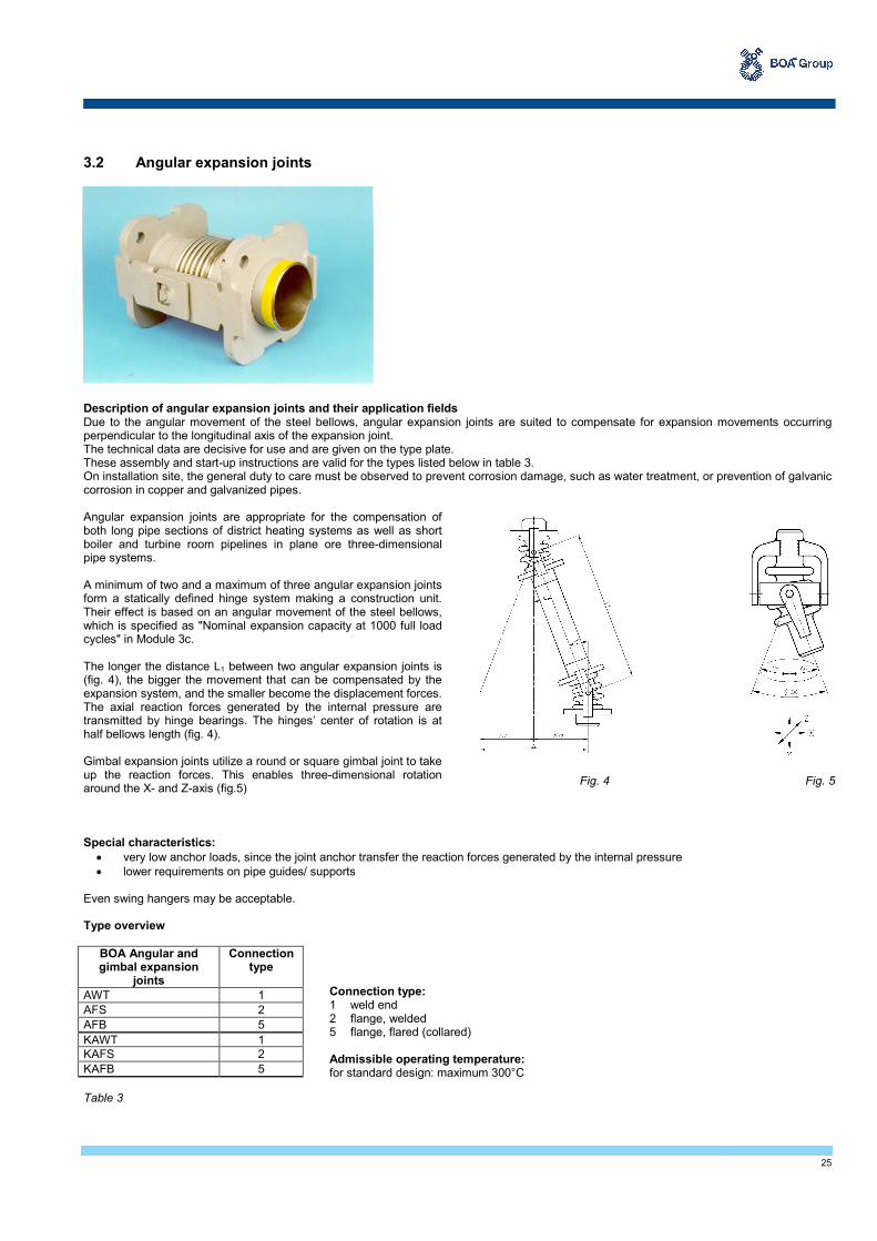
3.2 Angular expansion joints Description of angular expansion joints and their application fields Due to the angular movement of the steel bellows, angular expansion joints are suited to compensate for expansion movements occurring perpendicular to the longitudinal axis of the expansion joint. The technical data are decisive for use and are given on the type plate. These assembly and start-up instructions are valid for the types listed below in table 3. On installation site, the general duty to care must be observed to prevent corrosion damage, such as water treatment, or prevention of galvanic corrosion in copper and galvanized pipes. Angular expansion joints are appropriate for the compensation of both long pipe sections of district heating systems as well as short boiler and turbine room pipelines in plane ore three-dimensional pipe systems. A minimum of two and a maximum of three angular expansion joints form a statically defined hinge system making a construction unit. Their effect is based on an angular movement of the steel bellows, which is specified as "Nominal expansion capacity at 1000 full load cycles" in Module 3c. The longer the distance L1 between two angular expansion joints is (fig. 4), the bigger the movement that can be compensated by the expansion system, and the smaller become the displacement forces. The axial reaction forces generated by the internal pressure are transmitted by hinge bearings. The hinges’ center of rotation is at half bellows length (fig. 4). Gimbal expansion joints utilize a round or square gimbal joint to take up the reaction forces. This enables three-dimensional rotation around the X- and Z-axis (fig.5) Special characteristics:
• very low anchor loads, since the joint anchor transfer the reaction forces generated by the internal pressure
• lower requirements on pipe guides/ supports
Even swing hangers may be acceptable.
Type overview
BOA Angular and gimbal expansion
joints
Connection type
AWT 1
AFS 2
AFB 5
KAWT 1
KAFS 2
KAFB 5
Table 3
Fig. 4 Fig. 5
Connection type: 1 weld end 2 flange, welded 5 flange, flared (collared) Admissible operating temperature: for standard design: maximum 300°C

26
3.3 Installation advice Assembly
• Anchor points and pipe guides must be firmly installed before filling and pressure testing the system.
• Expansion joints must be installed without being subject to torsion.
• The steel bellows must be protected against damage and dirt (e.g. welding, plaster or mortar splatter).
• Steam pipelines should be installed in such a way that water hammers are avoided. This can be achieved by adequate drainage, insu-lation, by preventing water pockets and by sufficient inclination of the line.
• Observe the flow direction while installing expansion joints with inner sleeves.
• Avoid the installation of expansion joints in the immediate vicinity of pressure reducers, hot steam coolers and shut-down valves, if high-frequency oscillations are expected due to turbulence. Otherwise special measures must be installed (e.g. thick-walled sleeves, perfo-rated disks, calming sections etc.).
• If high frequency vibrations or turbulence or high flow speed are expected, we recommend the installation of expansion joints with inner sleeve.
• Inner sleeves are also recommended for expansion joints with DN ≥ 150, if the flow speed of air, gas or steam media exceeds 8 m/s, or 3 m/s in case of liquid media.
Pipe guides, pipe supports
• When installing angular and gimbal expansion joints (fig. 6), which can take up lateral expansion only in one plane, pay attention to consistency between the di-rection of the pipe expansion and the movement capability of the expansion joints (perpendicular to the bolt axis). The nominal angular expansion capacity can be taken from Module 3c. Angular expansion joints have no special de-mands on guide supports. For short-leg boiler and turbine room pipelines guide bearing is not necessary.
• The weight of the pipeline (including medium and insulation) and all wind and additional loads must be absorbed by suitable pipe hangers or supports. Move-ments of the expansion joint must not be hindered!
• Long pipe sections before and after the hinge system need a guide support.
Anchor points
• Only one hinge system is allowed between two anchor points. The anchor points must absorb the inherent resistance of the expan-sion joint, resulting from the bending resistance of the bellows and the pin friction of the hinge supports as well as the frictional forces of the guides/supports.
NOTE Pipe guides with excessive frictional resistance resulting from a too high surface pressure, dirt or corrosion deposits may block and cause considerable pressure peaks in the pipeline, its anchors and connections.
Fig. 6
Diagram 1
Steam / gas
Nominal size DN
Flo
w s
pee
d
v [m
/s]
Liquid

27
Prerestraint Angular and lateral expansion joints are usually installed with 50% prerestraint of their expansion capacity. It is advisable to carry out prere-straining on the completely installed system.
• While prerestraining, consider the installation temperature of the pipeline, particularly for above ground level pipelines.
• If the installation temperature differs from the lowest design temperature, reduce the prerestraint in accordance with the prerestraint di-agram 2
Prerestraint diagram Example to diagram 2 Hinge system for a pipeline measuring 140 m in length: Lowest temperature is -7°C. Highest temperature is +293°C. The maximum anticipated thermal movement equals 500 mm at the temperature difference of 300°C. The hinge system or expansion joint shall be prerestrained by 50% of the pipelines expansion = 250mm (i.e. acting in opposite direction of the pipeline movement). While installing, pay special attention to the correct restraining. Temperature while installing shall not be -7°C but +20°C. This re-sults in a thermal expansion of the pipeline of 45 mm (see diagram 2). This amount must be subtracted from the original prerestraint value of the hinge system or expansion joint: 250 – 45 = 205 mm. The prerestraint diagram (2) allows determining the prerestraint value directly without calculation: 1. Temperature difference between installation temperature and lowest temperature: +20°C – (-7°C) = 27°C. 2. Length of pipeline to be compensated for: 140 m 3. Draw a vertical line from the "27°C" point towards the beam com-ing from "0 - 140m". 4. Draw a horizontal line from this intersection to the line "Thermal expansion of pipeline in mm"; the result is, as stated above, 45 mm. 5. Draw a straight line from the "45 mm" point to "Total anticipated movement", this equals 500 mm, and go further to "Prerestraint of hinge system/ expansion joint in mm". The intersection shows a prerestraint of 205 mm. This is the value by which the hinge system must be prerestrained during installation.
Diagram 2
.
205
Prerestraint of expansion joint in mm

28
www.boagroup.com Subject to changes 15-11