e-compass sensor toolbox user’s guide · e-compass sensor toolbox user guide 1 introduction this...
TRANSCRIPT

Freescale Semiconductor Document Number: ECOMPASSSTUGUser Guide Rev. 2, 04/2013
© 2012-2013 Freescale Semiconductor, Inc. All rights reserved.
Contents
E-Compass Sensor Toolbox User Guide
1 IntroductionThis User’s Guide describes the operation of the Freescale Sensor Toolbox e-compass and magnetic calibration software which supports the two e-compass evaluation kits identified in Table 1.
The e-compass kits are for the MAG3110, MMA8451 and FXOS8700CQ devices which are part of the Freescale Xtrinsic sensor portfolio.
1.1 Kit ContentsThe two kits contain the parts shown in Table 2.
Table 1. E-Compass Kits and Usage
Kit Number For Device
RD4247MAG3110 MAG3110
MMA8451
RD4247FXOS8700 FXOS8700CQ
1 Introduction . . . . . . . . . . . . . . . . . . . . . . . . . . . . . . . . . . . 11.1 Kit Contents. . . . . . . . . . . . . . . . . . . . . . . . . . . . . . . 11.2 System Requirements . . . . . . . . . . . . . . . . . . . . . . . 21.3 Reference C Source Code Available Under
Click-Through License. . . . . . . . . . . . . . . . . . . . . . . 22 Hardware Assembly . . . . . . . . . . . . . . . . . . . . . . . . . . . . 23 Software Installation . . . . . . . . . . . . . . . . . . . . . . . . . . . . 34 Quick Start Demonstration . . . . . . . . . . . . . . . . . . . . . . . 55 eCompass Software Interface Screen. . . . . . . . . . . . . . . 7
5.1 Magnetometer Frame . . . . . . . . . . . . . . . . . . . . . . . 75.2 Accelerometer Frame . . . . . . . . . . . . . . . . . . . . . . . 85.3 Calibrated Mag Frame. . . . . . . . . . . . . . . . . . . . . . . 85.4 Hard Iron Vector and Inverse Soft Iron
Matrix Frames . . . . . . . . . . . . . . . . . . . . . . . . . . . . . 95.5 Compass Frame . . . . . . . . . . . . . . . . . . . . . . . . . . . 95.6 Calibration Frame . . . . . . . . . . . . . . . . . . . . . . . . . 105.7 Orientation and Virtual Gyro Frame . . . . . . . . . . . 11
6 Orientation Screen. . . . . . . . . . . . . . . . . . . . . . . . . . . . . 146.1 Euler Angles (deg) Frame . . . . . . . . . . . . . . . . . . . 156.2 Quaternion Frame . . . . . . . . . . . . . . . . . . . . . . . . . 156.3 Angle and Axis Frame . . . . . . . . . . . . . . . . . . . . . . 166.4 Rotation Matrix Frame. . . . . . . . . . . . . . . . . . . . . . 16
7 Navigation Screen . . . . . . . . . . . . . . . . . . . . . . . . . . . . . 168 Advanced Settings Screen . . . . . . . . . . . . . . . . . . . . . . 179 Data Log File Format. . . . . . . . . . . . . . . . . . . . . . . . . . . 1810 Calibration Save File Format . . . . . . . . . . . . . . . . . . . . . 2011 Using the USB Interface Board and Sensor Interface
Board with other Sensor Daughter Boards . . . . . . . . . . 2212 Related Documentation and Revision History . . . . . . . . 23

E-Compass Sensor Toolbox User’s Guide, Rev. 2
2 Freescale Semiconductor, Inc.
1.2 System RequirementsThe RD4247MAG3110 and RD4247FXOS8700 kits require the following:
• Windows® XP, Windows 7, or Vista in 32- and 64-bit versions• Freescale's sensor toolbox software available for download at:
http://www.freescale.com/sensortoolbox• Adobe® Shockwave®
If Shockwave is not installed on your PC, follow the installation instructions at:
http://get.adobe.com/shockwave/
1.3 Reference C Source Code Available Under Click-Through License
The e-compass and magnetic calibration algorithms in this Sensor Toolbox demonstration are offered free of charge for use with Freescale sensors. The fact sheet, ECOMPASSFS.pdf, and the reference software are available for download at:
http://www.freescale.com/ecompass.
2 Hardware AssemblyThe RD4247MAG3110 and RD4247FXOS8700 kits enable a PC to communicate with the sensor devices using a USB cable. This section explains assembly of the kit’s hardware which is shown in Figure 1.
To assemble the Sensor Toolbox kit’s hardware:1. Align the Pin-1 arrow of the daughter board to the Pin-1 arrow of the interface board.2. Insert the daughter board to the Sensor interface board.3. Insert the assembled daughter and interface boards into the LFSTBUSB USB interface board.
When the board assembly is complete, the compass pointing direction is as shown by the red, Compass Pointing Direction arrow in Figure 1.
4. Plug one end of the USB cable to the assembled boards and the other end to a spare USB port.
Table 2. E-Compass Kits’ Contents
Kit Contains
RD4247MAG3110 Daughter board with MMA8451 accelerometer and MAG3110 magnetometer
Sensor interface board
LFSTBUSB USB interface board
RD4247FXOS8700 Daughter board with FXOS8700CQ single-package accelerometer and magnetometer
Sensor interface board
LFSTBUSB USB interface board

E-Compass Sensor Toolbox User’s Guide, Rev. 2
Freescale Semiconductor, Inc. 3
Figure 1. PCB assembly
3 Software InstallationThis installation procedure is for the e-compass software release v6.1.0.0 and later as developed for the RD4247MAG3110 and RD4247FXOS8700 Sensor Toolbox kits.
Installation1. Navigate a web browser to freescale.com/sensortoolbox and click Download Software for
eCompass kits.2. Read the Freescale software license agreement and click I Accept to download the installer.3. Click Save and specify the location on your PC for storage of the installation file.4. Extract the zip file to a location of your choosing.5. Double-click on the setup file and follow the installation instructions.
Launch1. At the end of installation, a desktop shortcut will appear. Double-click on the shortcut to run the
e-compass software.a) If the Sensor Toolbox board does not have the compatible firmware flashed, one of two
notification windows in Figure 2 will be displayed.
Figure 2. Incompatible or old firmware messages
Sensor daughter board with
Sensor interface board
USB interface board
MMA8451 accelerometer and MAG3110 magnetometer

E-Compass Sensor Toolbox User’s Guide, Rev. 2
4 Freescale Semiconductor, Inc.
b) Click OK, and the firmware upload progress window appears as shown in Figure 3.
Figure 3. Upload progress screen
2. The launch screen shown in Figure 4 will appear. Click the eCompass button to launch the application.
Figure 4. E-Compass software launch screen
The application is now ready for use. (See the Section 4, “Quick Start Demonstration”.)The Navigation screen uses a Google Maps™ demonstration powered by Adobe® Shockwave®. See Section 1.2, “System Requirements” for download information.
E-Compass Sensor Toolbox User’s Guide, Rev. 2
Freescale Semiconductor, Inc. 5
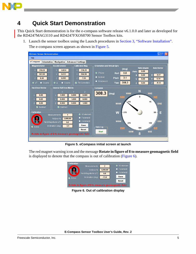
4 Quick Start DemonstrationThis Quick Start demonstration is for the e-compass software release v6.1.0.0 and later as developed for the RD4247MAG3110 and RD4247FXOS8700 Sensor Toolbox kits.
1. Launch the sensor toolbox using the Launch procedures in Section 3, “Software Installation”.The e-compass screen appears as shown in Figure 5.
Figure 5. eCompass initial screen at launch
The red magnet warning icon and the message Rotate in figure of 8 to measure geomagnetic field is displayed to denote that the compass is out of calibration (Figure 6).
Figure 6. Out of calibration display
This needs to be a full view ofthe display with the “out of calibration”window showing.

E-Compass Sensor Toolbox User’s Guide, Rev. 2
6 Freescale Semiconductor, Inc.
2. Ensure that the e-compass PCB assembly is held away from any source of magnetic interference such as magnets, steel desks or filing cabinets, or a notebook PC, and then rotate the PCB assembly about its three axes.The magnetometer sensor measures the earth's geomagnetic field at different orientations. When a minimum of 40 measurements is available, the calibration software computes the sensor and the PCB assembly’s magnetic calibration parameters. The calibration quality icon will then display four or five green bars denoting a high quality calibration, the advisory text will display Calibrated and the calibration Fit Error % should be 5% or less.
Figure 7. In calibration display
The e-compass is now calibrated and will display the correct e-compass pointing direction on the dial in the Compass frame as shown in Figure 8.
Figure 8. E-Compass heading display

E-Compass Sensor Toolbox User’s Guide, Rev. 2
Freescale Semiconductor, Inc. 7
5 eCompass Software Interface ScreenThis section describes in detail each element of the eCompass screen shown in Figure 9.
Figure 9. eCompass screen
5.1 Magnetometer FrameThe Magnetometer frame displays the parameters of the raw magnetometer measurement—that is, before correction for hard and soft iron magnetic interference, but after mapping to the selected operating system coordinate frame (iPhone®, Android™ or Windows 8).
The units of the measurement can be toggled between µT and integer bit counts using the uT and Counts radio buttons.
Figure 10. Magnetometer frame
E-Compass Sensor Toolbox User’s Guide, Rev. 2
8 Freescale Semiconductor, Inc.
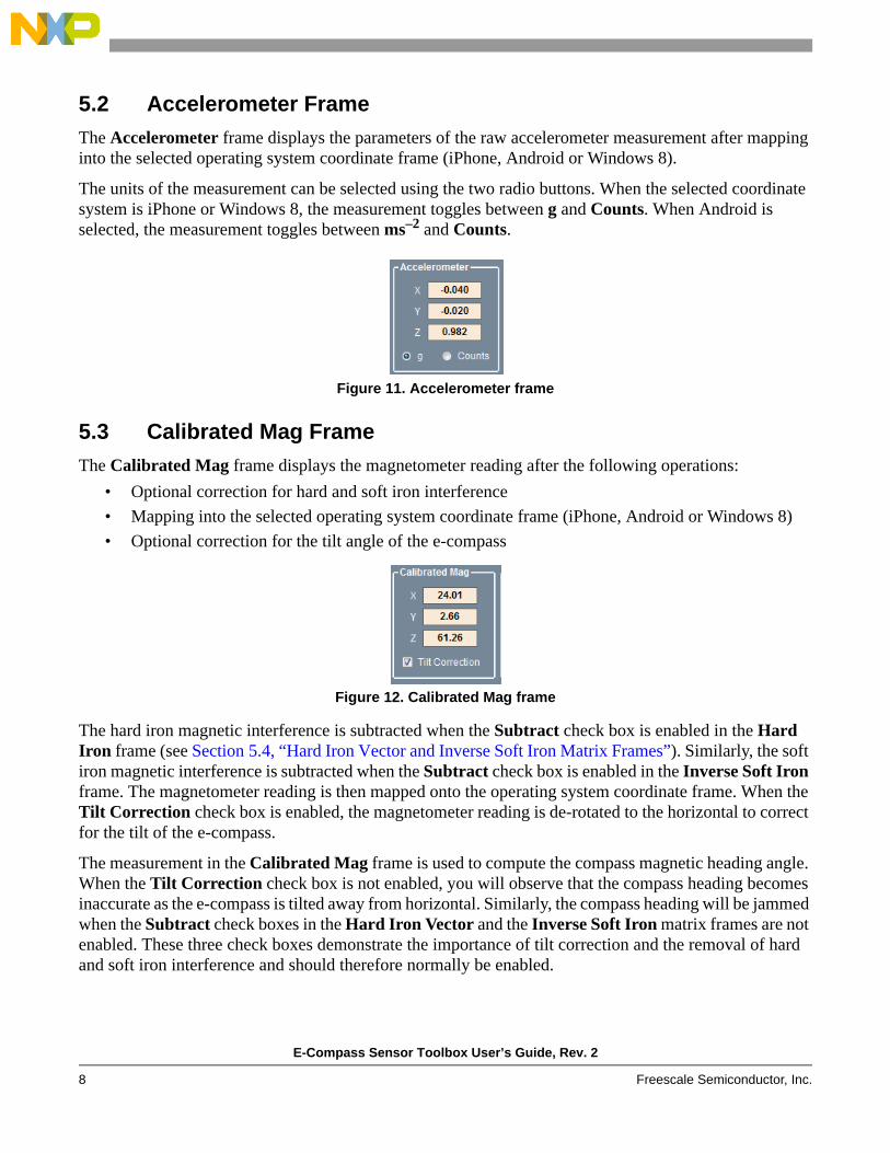
5.2 Accelerometer FrameThe Accelerometer frame displays the parameters of the raw accelerometer measurement after mapping into the selected operating system coordinate frame (iPhone, Android or Windows 8).
The units of the measurement can be selected using the two radio buttons. When the selected coordinate system is iPhone or Windows 8, the measurement toggles between g and Counts. When Android is selected, the measurement toggles between ms–2 and Counts.
Figure 11. Accelerometer frame
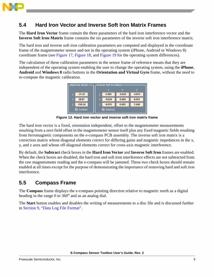
5.3 Calibrated Mag FrameThe Calibrated Mag frame displays the magnetometer reading after the following operations:
• Optional correction for hard and soft iron interference• Mapping into the selected operating system coordinate frame (iPhone, Android or Windows 8) • Optional correction for the tilt angle of the e-compass
Figure 12. Calibrated Mag frame
The hard iron magnetic interference is subtracted when the Subtract check box is enabled in the Hard Iron frame (see Section 5.4, “Hard Iron Vector and Inverse Soft Iron Matrix Frames”). Similarly, the soft iron magnetic interference is subtracted when the Subtract check box is enabled in the Inverse Soft Iron frame. The magnetometer reading is then mapped onto the operating system coordinate frame. When the Tilt Correction check box is enabled, the magnetometer reading is de-rotated to the horizontal to correct for the tilt of the e-compass.
The measurement in the Calibrated Mag frame is used to compute the compass magnetic heading angle. When the Tilt Correction check box is not enabled, you will observe that the compass heading becomes inaccurate as the e-compass is tilted away from horizontal. Similarly, the compass heading will be jammed when the Subtract check boxes in the Hard Iron Vector and the Inverse Soft Iron matrix frames are not enabled. These three check boxes demonstrate the importance of tilt correction and the removal of hard and soft iron interference and should therefore normally be enabled.
E-Compass Sensor Toolbox User’s Guide, Rev. 2
Freescale Semiconductor, Inc. 9
5.4 Hard Iron Vector and Inverse Soft Iron Matrix FramesThe Hard Iron Vector frame contain the three parameters of the hard iron interference vector and the Inverse Soft Iron Matrix frame contains the six parameters of the inverse soft iron interference matrix.
The hard iron and inverse soft iron calibration parameters are computed and displayed in the coordinate frame of the magnetometer sensor and not in the operating system (iPhone, Android or Windows 8) coordinate frame (see Figure 17, Figure 18, and Figure 19 for the operating system differences).
The calculation of these calibration parameters in the sensor frame of reference means that they are independent of the operating system enabling the user to change the operating system, using the iPhone, Android and Windows 8 radio buttons in the Orientation and Virtual Gyro frame, without the need to re-compute the magnetic calibration.
Figure 13. Hard iron vector and inverse soft iron matrix frame
The hard iron vector is a fixed, orientation independent, offset to the magnetometer measurements resulting from a zero field offset in the magnetometer sensor itself plus any fixed magnetic fields resulting from ferromagnetic components on the e-compass PCB assembly. The inverse soft iron matrix is a correction matrix whose diagonal elements correct for differing gains and magnetic impedances in the x, y, and z axes and whose off-diagonal elements correct for cross-axis magnetic interference.
By default, the Subtract check boxes in the Hard Iron Vector and Inverse Soft Iron frames are enabled. When the check boxes are disabled, the hard iron and soft iron interference effects are not subtracted from the raw magnetometer reading and the e-compass will be jammed. These two check boxes should remain enabled at all times except for the purpose of demonstrating the importance of removing hard and soft iron interference.
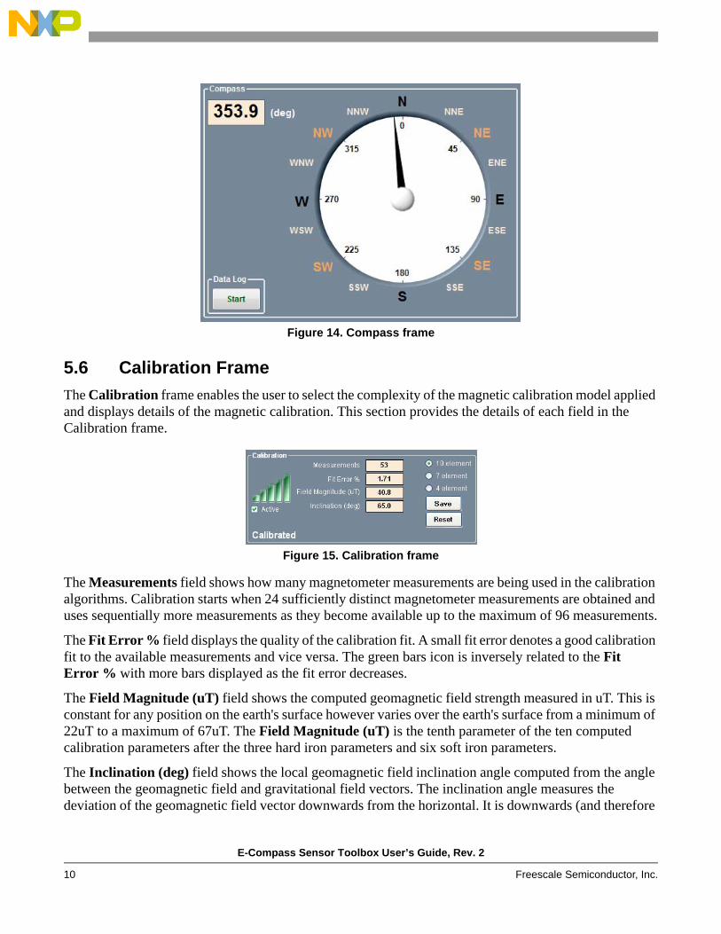
5.5 Compass FrameThe Compass frame displays the e-compass pointing direction relative to magnetic north as a digital heading in the range 0 to 360o and as an analog dial.
The Start button enables and disables the writing of measurements to a disc file and is discussed further in Section 9, “Data Log File Format”.
E-Compass Sensor Toolbox User’s Guide, Rev. 2
10 Freescale Semiconductor, Inc.
Figure 14. Compass frame
5.6 Calibration FrameThe Calibration frame enables the user to select the complexity of the magnetic calibration model applied and displays details of the magnetic calibration. This section provides the details of each field in the Calibration frame.
Figure 15. Calibration frame
The Measurements field shows how many magnetometer measurements are being used in the calibration algorithms. Calibration starts when 24 sufficiently distinct magnetometer measurements are obtained and uses sequentially more measurements as they become available up to the maximum of 96 measurements.
The Fit Error % field displays the quality of the calibration fit. A small fit error denotes a good calibration fit to the available measurements and vice versa. The green bars icon is inversely related to the Fit Error % with more bars displayed as the fit error decreases.
The Field Magnitude (uT) field shows the computed geomagnetic field strength measured in uT. This is constant for any position on the earth's surface however varies over the earth's surface from a minimum of 22uT to a maximum of 67uT. The Field Magnitude (uT) is the tenth parameter of the ten computed calibration parameters after the three hard iron parameters and six soft iron parameters.
The Inclination (deg) field shows the local geomagnetic field inclination angle computed from the angle between the geomagnetic field and gravitational field vectors. The inclination angle measures the deviation of the geomagnetic field vector downwards from the horizontal. It is downwards (and therefore

E-Compass Sensor Toolbox User’s Guide, Rev. 2
Freescale Semiconductor, Inc. 11
positive) in the northern hemisphere. The magnetic inclination angle should not be confused with the magnetic declination angle which is the angle by which the geomagnetic field direction deviates from true geomagnetic north.
The 10 element, 7 element and 4 element radio buttons determine the complexity of the calibration model fitted to the stored magnetometer measurements.
• The 10 parameters of the 10 element model as discussed in Section 5.4, “Hard Iron Vector and Inverse Soft Iron Matrix Frames”:— three elements of the hard iron vector— six elements of the soft iron matrix— geomagnetic field strength
• The 7 element model fits a simplified soft iron matrix with three non-zero elements on the leading diagonal but with zero off-diagonal elements. The three hard iron vector components and the geomagnetic field strength are, however, retained giving a total of 7 fitted calibration elements.
• The 4 element model further simplifies the soft iron matrix to an identity matrix but again retains the three hard iron vector components and the geomagnetic field strength giving a total of 4 fitted calibration elements.
The Active check box enables and disables the updating of the magnetic calibration. This should normally be left enabled because the calibration software contains intelligent algorithms to determine whether or not to update the magnetic calibration. If the magnetic calibration needs to be frozen for any reason, simply disable this check box.
The Save button prompts for a disc filename and writes out details of the measurements stored in the magnetic buffer and additional details of the calibration. The file format is discussed further in Section 10, “Calibration Save File Format”.
The Reset button performs the equivalent of a power on reset. The magnetometer measurement buffer is flushed and the calibration reset.
5.7 Orientation and Virtual Gyro FrameThe Orientation and Virtual Gyro Frame enables users to select among the operating systems iPhone, Android and Windows 8 using the respective radio button.
Figure 16. Orientation and virtual gyro frame
The Roll, Pitch and Yaw fields are the three Euler angles which define the orientation of the PCB assembly relative to a starting position when the e-compass is flat and pointing northwards. For the iPhone and Android standards, the compass heading angle equals the yaw angle. For Windows 8, however, the compass heading angle is the negative of the yaw angle.

E-Compass Sensor Toolbox User’s Guide, Rev. 2
12 Freescale Semiconductor, Inc.
The iPhone also known as the aerospace or NED (x=North, y=East, z=Down) coordinate system is shown in Figure 17 together with hypothetical FXOS8700CQ sensor coordinates (in yellow). The FXOS8700CQ sensor frame depends on the orientation of the device on the circuit board and may not be aligned with the operating system coordinate frame. The sensor and operating system coordinate frames are automatically aligned by the software using the Hardware Abstraction Layer (HAL) matrices displayed in the Advanced Settings tab.
Figure 17. iPhone or aerospace NED coordinate system
The Android coordinate system is shown in Figure 18 together with hypothetical FXOS8700CQ sensor coordinates (in yellow). This is an example of an ENU (x=East, y=North, z=Up) coordinate system. Note that the Android rotation angles are defined with the opposite sign to standard mathematical usage.
Figure 18. Android coordinate system
N, x
E, y
D, z
Compass Pointing Direction
Roll ϑ-180 to 180 deg
Yaw ϑ0 to 360 deg
Pitch ϑ-90 to 90 deg
xz
y
Pitch θYaw ψ
Roll φ
N, y
E, x
U, z
Compass Pointing Direction
Roll ϑ-90 to 90 degYaw ϑ
0 to 360 deg
Pitch ϑ-180 to 180 deg
xz
y
Pitch θ
Yaw ψ Roll φ

E-Compass Sensor Toolbox User’s Guide, Rev. 2
Freescale Semiconductor, Inc. 13
The Windows 8 coordinate system is shown in Figure 19 together with hypothetical FXOS8700CQ sensor coordinates (in yellow). This is another example of an ENU (x=East, y=North, z=Up) coordinate system but notice that the rotation angles are specified in the normal mathematical usage and therefore opposite in sense to Android. As a result, the Windows 8 Compass heading angle is 360 degrees minus the Windows 8 yaw angle.
Figure 19. Windows 8 coordinate system
The iPhone coordinate system defines the sign of the accelerometer output so as to measure positive gravity or the negative of linear acceleration. When the e-compass is flat on the table with the z axis pointed down and aligned with gravity, the iPhone z axis reading is therefore +1g.
The Android coordinate system takes the opposite approach and defines the accelerometer output to be positive for acceleration and negative for gravity. When the e-compass is flat on the table, the z axis is pointed upwards giving a negative acceleration (positive gravity) aligned along the downwards negative z axis. The resulting measurement is therefore positive and, because Android uses units of ms–2 in preference to g, has a value of 9.81 ms–2.
The Windows 8 coordinate system differs again and defines the acceleration output to be positive for gravity and negative for linear acceleration. When the e-compass is flat on the table, the z axis is pointed upwards giving a negative gravitational reading of –1g because Windows 8 measures acceleration in units of g.
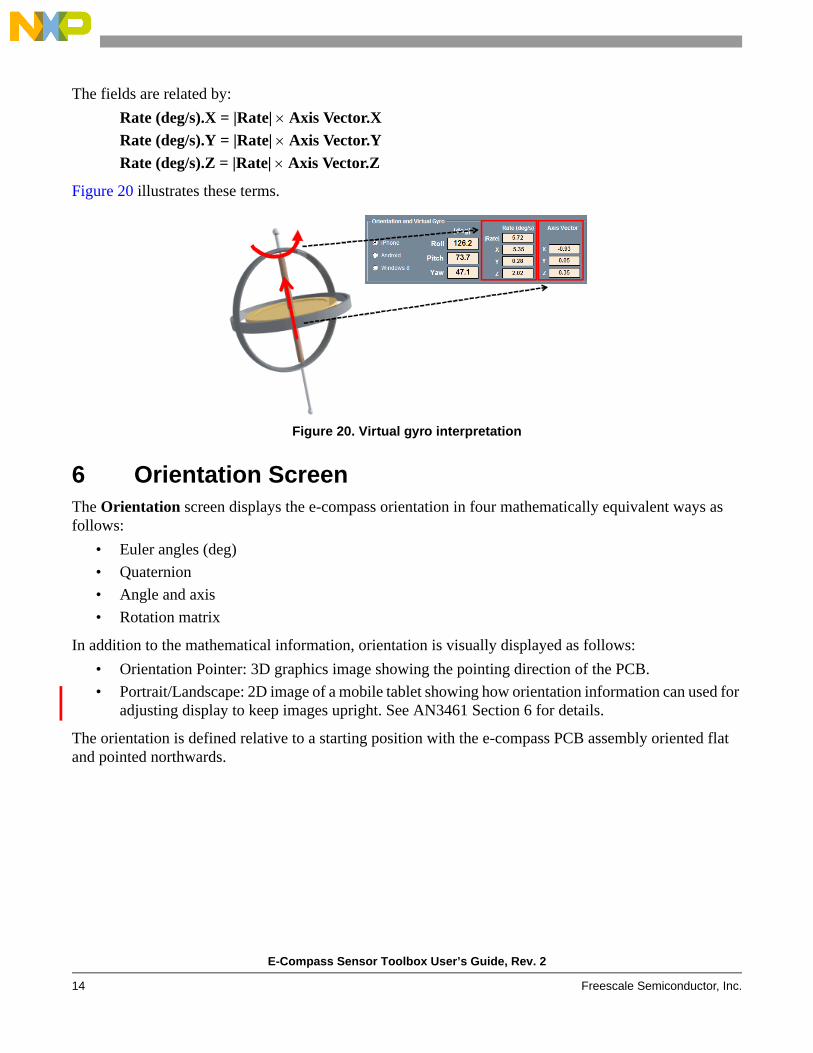
The remaining seven fields show the output from the virtual gyro computed from the accelerometer and magnetometer sensors. A real gyro sensor directly measures angular rotation rates, whereas a virtual gyro indirectly computes the rotation rate from the accelerometer and magnetometer sensors on the assumption of zero linear acceleration.
The Axis Vector X, Y and Z fields show the three x, y, and z parameters of the normalized instantaneous axis about which the e-compass is rotating.
The |Rate| field shows the total angular velocity in degrees per second about this axis. The X, Y and Z parameters show the x, y, and z parameters of the angular velocity.
N, y
E, x
U, z
Compass Pointing Direction
Roll ∗-90 to 90 degYaw ∗
0 to 360 deg
Pitch ∗-180 to 180 deg
Pitch θ
Yaw ψRoll φ
E-Compass Sensor Toolbox User’s Guide, Rev. 2
14 Freescale Semiconductor, Inc.
The fields are related by:Rate (deg/s).X = |Rate| × Axis Vector.XRate (deg/s).Y = |Rate| × Axis Vector.YRate (deg/s).Z = |Rate| × Axis Vector.Z
Figure 20 illustrates these terms.
Figure 20. Virtual gyro interpretation
6 Orientation ScreenThe Orientation screen displays the e-compass orientation in four mathematically equivalent ways as follows:
• Euler angles (deg)• Quaternion• Angle and axis• Rotation matrix
In addition to the mathematical information, orientation is visually displayed as follows:• Orientation Pointer: 3D graphics image showing the pointing direction of the PCB.• Portrait/Landscape: 2D image of a mobile tablet showing how orientation information can used for
adjusting display to keep images upright. See AN3461 Section 6 for details.
The orientation is defined relative to a starting position with the e-compass PCB assembly oriented flat and pointed northwards.

E-Compass Sensor Toolbox User’s Guide, Rev. 2
Freescale Semiconductor, Inc. 15
Figure 21. Orientation screen
6.1 Euler Angles (deg) FrameThe Euler Angles (deg) frame shows the same Roll, Pitch, Yaw and Compass orientation angles displayed on the eCompass screen shown in Figure 9.
6.2 Quaternion FrameThe Quaternion frame shows the four parameters of the rotation quaternion for the e-compass orientation. When the current e-compass orientation results from a rotation by angle η about the normalized rotation axis n, then the quaternion q has the value:
Eqn. 1
where:
Eqn. 2
The scalar and vector parameters of the quaternion have the values provided in Equation 3.
q η2---⎝ ⎠⎛ ⎞ n η
2---⎝ ⎠⎛ ⎞sin+cos=
n nxi nyj nzk+ +=

E-Compass Sensor Toolbox User’s Guide, Rev. 2
16 Freescale Semiconductor, Inc.
Eqn. 3
6.3 Angle and Axis FrameThe Angle and Axis frame displays the same information as the Quaternion frame but in a more intuitive manner.
The Deg field is the rotation angle η in units of degrees.
The X, Y, and Z fields display the three components of the normalized rotation axis .
6.4 Rotation Matrix FrameThe Rotation Matrix frame contains the 3x3 rotation matrix R defining the orientation of the e-compass PCB assembly. It is related to the orientation quaternion by:
Eqn. 4
7 Navigation ScreenThe Navigation screen uses the three e-compass orientation angles, roll, pitch, and compass heading, to navigate the Google Maps display. The roll and pitch angles move the display in the horizontal x and y directions respectively while the compass angle rotates the display.
For this demonstration to function the PC must be connected to the internet and Adobe Shockwave must be installed. See Section 1.2, “System Requirements” for download information.
q0n2---⎝ ⎠⎛ ⎞cos=
qx nxn2---⎝ ⎠⎛ ⎞sin=
qy nyn2---⎝ ⎠⎛ ⎞sin=
qz nzn2---⎝ ⎠⎛ ⎞sin=
n̂
R
2 q0
2 qx2+( ) 1– 2 qxqy q0qz+( ) 2 qxqz q0qy–( )
2 qxqy q0qz–( ) 2 q0
2 qy2+( ) 1– 2 qyqz q0qx+( )
2 qxqz q0qy+( ) 2 qyqz q0qx–( ) 2 q0
2 qz2+( ) 1–
=

E-Compass Sensor Toolbox User’s Guide, Rev. 2
Freescale Semiconductor, Inc. 17
Figure 22. Navigation screen
8 Advanced Settings ScreenThe Advanced Settings screen enables the user to select advanced controls, although the user is seldom required to change these settings. This section explains each field of the Advanced Settings screen.
Figure 23. Advanced settings screen
E-Compass Sensor Toolbox User’s Guide, Rev. 2
18 Freescale Semiconductor, Inc.
The Magnetometer Alignment HAL frame and the Accelerometer Alignment HAL frame contain the Hardware Abstraction Layer (HAL) matrices used to align the magnetometer and accelerometer sensor x, y, and z axes to the coordinate system of the current operating system. The HAL matrices are automatically changed when the operating system is changed among the iPhone, Android and Windows 8 operating systems and there is normally no need for the user to change these settings.
The Orientation and Virtual Gyro Low Pass Filters frame includes the Averaging (samples) menu enabling the user to set the 1/e time constant (in samples) of the single pole exponential low pass filter smoothing on the roll, pitch, yaw and compass heading angles and the virtual gyro data. The default setting is 16 samples which equates to 0.32s 1/e convergence at the default 50Hz sampling frequency.
The Magnetic Calibration Settings frame includes the Calibration Interval (samples) menu and enables the user to change the interval (in samples) between each execution of the calibration. The default value is 40 samples, which at a sampling rate of 50Hz corresponds to a calibration every 0.8s.
The Sampling Rate frame displays the current sampling rate and internal settings of the magnetometer sensor. This is not adjustable by the user.
The Platform Information frame displays details of the specific sensors being used.
The Reset button returns the contents of the Advanced Settings screen to their default values.
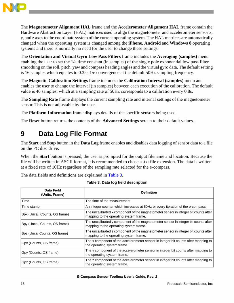
9 Data Log File FormatThe Start and Stop button in the Data Log frame enables and disables data logging of sensor data to a file on the PC disc drive.
When the Start button is pressed, the user is prompted for the output filename and location. Because the file will be written in ASCII format, it is recommended to chose a .txt file extension. The data is written at a fixed rate of 10Hz regardless of the sampling rate selected for the e-compass.
The data fields and definitions are explained in Table 3.Table 3. Data log field description
Data Field(Units, Frame)
Definition
Time The time of the measurement
Time stamp An integer counter which increases at 50Hz or every iteration of the e-compass.
Bpx (Uncal, Counts, OS frame)The uncalibrated x component of the magnetometer sensor in integer bit counts after mapping to the operating system frame.
Bpy (Uncal, Counts, OS frame)The uncalibrated y component of the magnetometer sensor in integer bit counts after mapping to the operating system frame.
Bpz (Uncal Counts, OS frame)The uncalibrated z component of the magnetometer sensor in integer bit counts after mapping to the operating system frame.
Gpx (Counts, OS frame)The x component of the accelerometer sensor in integer bit counts after mapping to the operating system frame.
Gpy (Counts, OS frame)The y component of the accelerometer sensor in integer bit counts after mapping to the operating system frame.
Gpz (Counts, OS frame)The z component of the accelerometer sensor in integer bit counts after mapping to the operating system frame.

E-Compass Sensor Toolbox User’s Guide, Rev. 2
Freescale Semiconductor, Inc. 19
Bpx (Uncal, uT, OS frame)The uncalibrated x component of the magnetometer sensor in uT after mapping to the operating system frame.
Bpy (Uncal, uT, OS frame)The uncalibrated y component of the magnetometer sensor in uT after mapping to the operating system frame.
Bpz (Uncal, uT, OS frame)The uncalibrated z component of the magnetometer sensor in uT after mapping to the operating system frame.
Gpx (g, OS frame)The x component of the accelerometer sensor in units of g (iPhone and Windows 8) or ms–2 (Android) in the operating system coordinate frame.
Gpy (g, OS frame)The y component of the accelerometer sensor in units of g (iPhone and Windows 8) or ms–2 (Android) in the operating system coordinate frame.
Gpz (g, OS frame)The z component of the accelerometer sensor in units of g (iPhone and Windows 8) or ms–2 (Android) in the operating system coordinate frame.
Bcx (Cal, uT, OS frame)The calibrated x component of the magnetometer sensor in uT in the operating system coordinate frame.
Bcy (Cal, uT, OS frame)The calibrated y component of the magnetometer sensor in uT in the operating system coordinate frame.
Bcz (Cal, uT, OS frame)The calibrated z component of the magnetometer sensor in uT in the operating system coordinate frame.
Hard iron x (uT, Magnetometer frame)The x component of the hard iron offset in units of uT in the magnetometer sensor coordinate frame.
Hard iron y (uT, Magnetometer frame)The y component of the hard iron offset in units of uT in the magnetometer sensor coordinate frame.
Hard iron z (uT, Magnetometer frame)The z component of the hard iron offset in units of uT in the magnetometer sensor coordinate frame.
Inv soft iron [x][x] (Magnetometer frame)The xx component of the inverse soft iron matrix in the magnetometer sensor coordinate frame.
Inv soft iron [x][y] (Magnetometer frame)The xy (and yx) component of the inverse soft iron matrix in the magnetometer sensor coordinate frame.
Inv soft iron [x][z] (Magnetometer frame)The xz (and zx) component of the inverse soft iron matrix in the magnetometer sensor coordinate frame.
Inv soft iron [y][y] (Magnetometer frame)The yy component of the inverse soft iron matrix in the magnetometer sensor coordinate frame.
Inv soft iron [y][z] (Magnetometer frame)The yz (and zy) component of the inverse soft iron matrix in the magnetometer sensor coordinate frame.
Inv soft iron [z][z] (Magnetometer frame)The zz component of the inverse soft iron matrix in the magnetometer sensor coordinate frame.
Roll (deg, OS frame) The roll angle as defined by the selected operating system.
Pitch (deg, OS frame) The pitch angle as defined by the selected operating system.
Yaw (deg, OS frame) The yaw angle as defined by the selected operating system.
Compass (deg, OS frame) The compass heading angle as defined by the selected operating system.
Virtual Gyro X (deg/s) The angular velocity around x-axis
Virtual Gyro Y (deg/s) The angular velocity around y-axis
Virtual Gyro Z (deg/s) The angular velocity around z-axis
Table 3. Data log field description (Continued)
Data Field(Units, Frame)
Definition

E-Compass Sensor Toolbox User’s Guide, Rev. 2
20 Freescale Semiconductor, Inc.
10 Calibration Save File FormatThe Save button in the Calibration frame of the eCompass screen enables advanced users to save and therefore visualize the magnetic calibration.
The user is prompted for the filename and folder for the calibration file. The calibration file is a simple tab delimited ASCII text file that can be opened with Notepad or Microsoft Excel® so a .txt file extension is recommended. Equation 1 provides a calibration file with annotations in italic.
Example 1. Calibration file
The magnetometer measurement buffer has 125 elementsMagnetic Buffer Size 125
The 10 element calibration model has been selectedNumber of calibration parameters 10
The components of the hard iron vector:Hard iron Vx (uT, magnetometer frame) -16.66Hard iron Vy (uT, magnetometer frame) 36.01Hard iron Vz (uT, magnetometer frame) -193.83
The components of the inverse soft iron matrix invWInverse Soft Iron (magnetometer frame) invW[x][x] [x][y] [x][z] 0.848 -0.126 0.003Inverse Soft Iron (magnetometer frame) invW[y][x] [y][y] [y][z] -0.126 1.167 -0.039Inverse Soft Iron (magnetometer frame) invW[z][x] [z][y] [z][z] 0.003 -0.039 1.028
The components of the magnetometer measurement ellipsoid matrix AEllipsoid matrix (magnetometer frame) A[x][x] [x][y] [x][z] 0.805 -0.080 0.065Ellipsoid matrix (magnetometer frame) A[y][x] [y][y] [y][z] -0.080 1.433 0.096Ellipsoid matrix (magnetometer frame) A[z][x] [z][y] [z][z] 0.065 0.096 0.885
The estimated geomagnetic field strength in uT at the current locationGeomagnetic field B (uT) 60.6
The low pass filtered estimate of the geomagnetic inclination angle in degGeomagnetic inclination (deg) 61.8
The fit error % (lower is better) of the current magnetic calibration to the measured dataCalibration fit error % 3.25
The number of magnetometer measurements used for the calibrationMeasurements used in calibration 67
The time stamp (integer counter) and the magnetometer components for elements in the measurement bufferTime stamp Bx (uT, magnetometer frame) By (uT, magnetometer frame) Bz (uT, magnetometer frame)63473 -30.10 5.20 -248.2063493 -49.90 14.20 -152.50…

E-Compass Sensor Toolbox User’s Guide, Rev. 2
Freescale Semiconductor, Inc. 21
63488 -1.20 32.80 -149.20264 -66.00 11.00 -233.80
The script in Example 2 can be copied and pasted into Mathematica to visualize the data distribution of raw and calibrated magnetic measurements. Copy the text between the lines of Example 2.
Example 2. Data to visualize the distribution of raw and calibrated magnetic measurements
rawdata={{-30.10,5.20,-248.20},{-49.90,14.20,-152.50},…{-69.80,32.90,-235.10},{-66.00,11.00,-233.80}}caldata={{-7.68,-32.15,-54.74},{-25.29,-22.89,43.24},…{-44.80,4.68,-42.48},{-38.81,-21.42,-40.28}}plot1 = ListPointPlot3D[rawdata, AxesLabel -> {Bx, By, Bz}, Axes -> True, BaseStyle -> {FontSize -> 14}, BoxRatios -> Automatic, PlotStyle -> Directive[Red, PointSize[0.02]]]a={{0.8046744,-0.07999535,0.06546545},{-0.07999535,1.432992,0.09600001},{0.06546545,0.09600001,0.8847731}}plot2=RegionPlot3D[{x-(-16.66085),y-(36.01439),z-(-193.8288)}.a.{x-(-16.66085),y-(36.01439),z-(-193.8288)}<3674.934,{x,-16.66085-120,-16.66085+120}, {y,36.01439-120,36.01439+120}, {z,-193.8288-120,-193.8288+120},PlotPoints -> 100, Mesh -> None, AxesLabel -> {Bx, By, Bz}, BaseStyle -> {FontSize -> 14}, AxesLabel -> Automatic, PlotStyle -> Opacity[0.5]]plot3 = ListPointPlot3D[caldata, AxesLabel -> {Bx, By, Bz}, Axes -> True, BaseStyle -> {FontSize -> 14}, BoxRatios -> Automatic, PlotStyle -> Directive[Blue, PointSize[0.02]]]plot4=RegionPlot3D[x*x+y*y+z*z<3674.934, {x,-100,100}, {y,-100,100}, {z,-100,100},
PlotPoints -> 100, Mesh -> None, AxesLabel -> {Bx, By, Bz}, BaseStyle -> {FontSize -> 14}, AxesLabel -> Automatic, PlotStyle -> Opacity[0.5]]Show[plot1, plot2, PlotRange -> Automatic]Show[plot3, plot4, PlotRange -> Automatic]Show[plot2, plot4, PlotRange -> Automatic]Show[plot1, plot2, plot3, plot4, PlotRange -> Automatic]
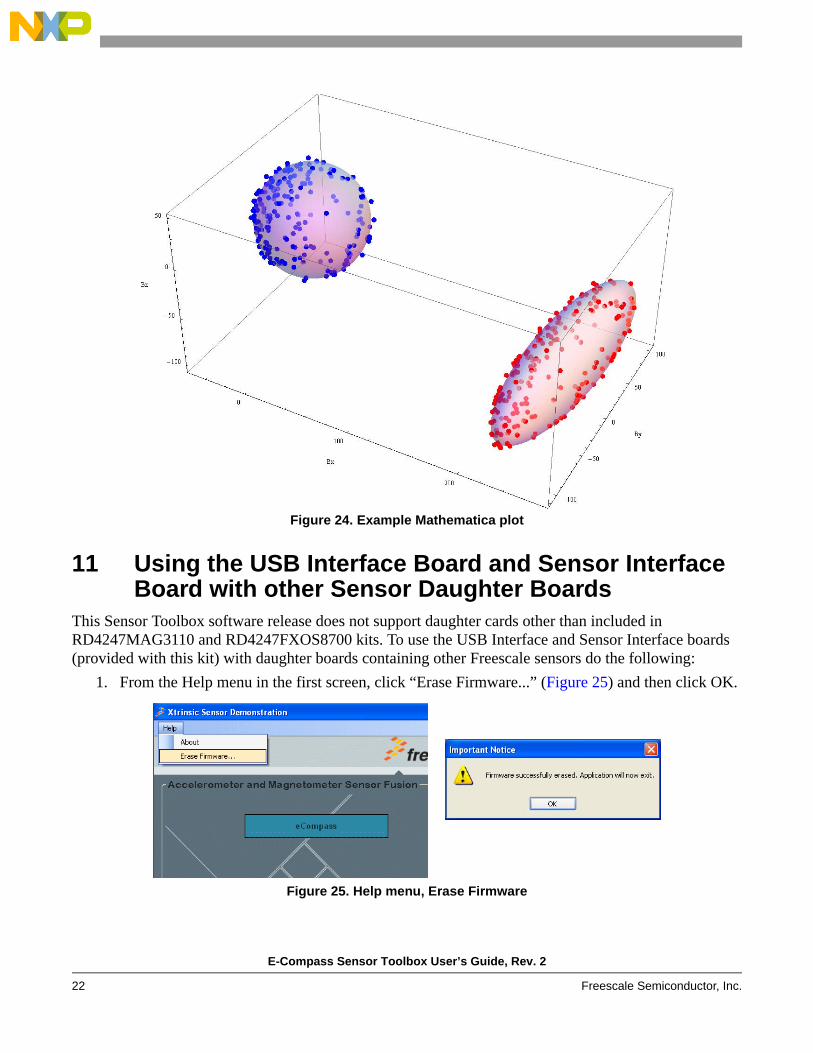
An example Mathematica plot is show in Figure 24.
E-Compass Sensor Toolbox User’s Guide, Rev. 2
22 Freescale Semiconductor, Inc.
Figure 24. Example Mathematica plot
11 Using the USB Interface Board and Sensor Interface Board with other Sensor Daughter Boards
This Sensor Toolbox software release does not support daughter cards other than included in RD4247MAG3110 and RD4247FXOS8700 kits. To use the USB Interface and Sensor Interface boards (provided with this kit) with daughter boards containing other Freescale sensors do the following:
1. From the Help menu in the first screen, click “Erase Firmware...” (Figure 25) and then click OK.
Figure 25. Help menu, Erase Firmware

E-Compass Sensor Toolbox User’s Guide, Rev. 2
Freescale Semiconductor, Inc. 23
2. Install and use the latest comprehensive (not the one for e-compass boards) Sensor Toolbox release from http://www.freescale.com/sensortoolbox.
12 Related Documentation and Revision HistoryThe features and operations of the FXOS8700CQ, MAG3110, and MMA8451 sensor devices are described in a variety of documents. To find the most-current versions of these documents and other, related documents:
1. Go to the Freescale homepage at:
http://www.freescale.com/2. In the Keyword search box at the top of the page, enter the device number.3. In the Refine Your Results area on the left, click Documentation.
Table 4. Revision History
Revision number
Revision date
Description of changes
1 12/2012
• Updated screen shots throughout for the change from software v5.0.0 to v6.0.0. • Expanded Section 3, “Software Installation” instructions. • Added visual orientation descriptions to Section 6, “Orientation Screen”. • Added Section 11, “Using the USB Interface Board and Sensor Interface Board with other Sensor
Daughter Boards”.
2 04/2013 • Added Section 1.3, “Reference C Source Code Available Under Click-Through License”. • Updated Section 4, “Quick Start Demonstration”.

ECOMPASSSTUGRev. 204/2013
Information in this document is provided solely to enable system and software
implementers to use Freescale products. There are no express or implied copyright
licenses granted hereunder to design or fabricate any integrated circuits based on the
information in this document.
Freescale reserves the right to make changes without further notice to any products
herein. Freescale makes no warranty, representation, or guarantee regarding the
suitability of its products for any particular purpose, nor does Freescale assume any
liability arising out of the application or use of any product or circuit, and specifically
disclaims any and all liability, including without limitation consequential or incidental
damages. “Typical” parameters that may be provided in Freescale data sheets and/or
specifications can and do vary in different applications, and actual performance may
vary over time. All operating parameters, including “typicals,” must be validated for each
customer application by customer’s technical experts. Freescale does not convey any
license under its patent rights nor the rights of others. Freescale sells products pursuant
to standard terms and conditions of sale, which can be found at the following address:
freescale.com/salestermsandconditions.
Freescale, the Freescale logo, CodeWarrior, ColdFire, Energy Efficient Solutions logo,
and Kinetis are trademarks of Freescale Semiconductor, Inc., Reg. U.S. Pat. & Tm. Off.
ColdFire+ and Xtrinsic are trademarks of Freescale Semiconductor, Inc.
All other product or service names are the property of their respective owners.
© 2013 Freescale Semiconductor, Inc. All rights reserved.
How to Reach Us:Home Page:freescale.comWeb Support:freescale.com/support