e-content of engineering graphics for the students …
TRANSCRIPT

E-CONTENT OF ENGINEERING GRAPHICS FOR THE STUDENTS OFCOMPUTER, ELECTRICAL & MECHANICAL ENGINEERING
PREPARED BY: - SH PAWAN BALODA& SH HITESH AGGARWAL
CHAPTER-6
GRAPHICS USING CAD
MEANING AND REQUIREMENT OF COMPUTER GRAPHICS
Computer graphics is the discipline of generating images with the help ofcomputers. Computer graphics is responsible for displaying art and image dataeffectively and meaningfully to the consumer. It is also used for processing imageand data received from the physical world.
COMPUTER-AIDED DESIGN (CAD)
It is the use of computers to aid in the creation, modification, analysis, oroptimization of a design. CAD software is used to
increase the productivity of the designer improve the quality of design improve communications through documentation to create a database for manufacturing
SCREEN STRUCTURE AND TOOLBARS
Toolbars contain buttons that start commands.
The Quick Access toolbar at the top of the application window is displayed bydefault. It contains frequently used commands as well as standard commands foropening and saving your file.
A toolbar is of two types
1. FLOATING TOOLBAR A floating toolbar can be displayed anywhere onscreen, and it can be drag it to a new location, resize it, or dock it.

2. DOCKED TOOLBAR A docked toolbar can be attached to any edge of thedrawing area.
AUTOCAD COORDINATE SYSTEMS
There are two different coordinate systems used in AutoCAD.
1. Cartesian (rectangular) Coordinate System It uses the “x” distance(left/right) and the “y” distance (up/down).
2. Polar Coordinate System It uses the distance between points (length ormagnitude) and the angle (direction or vector).
DRAWING LIMITS
It Sets limits to the boundary and size of the current drawing. The user mustspecify the lower left-hand corner and the upper right-hand corner. This settingmay be turned on or off – when on, points may not be specified outside thecurrently set limits.

UNITS
It specifies the display format and precision. This command dictates whether theunits are displayed as decimals or as a fraction, as well as how many decimalplaces the number will go. Also specifies how angles will be represented, either asdecimal degrees, radians, etc., as well as how angles will be measured, i.e.clockwise vs. counterclockwise.
COMMANDS FOR DRAWING ENTITIES
Line: It allows the sequential drawing of one or more straight lines. Once engaged,this command elicits a prompt of “From point:”, at which point the user specifies astarting point for a line, or they may press RETURN, which starts the line at theend of the previous line or arc that was drawn. Next, the prompt “To point:” isdisplayed, allowing the user to specify a sequence of points to which the line willextend. They may also type the letter C to close the polygon, or the letter U to undothe previous line segment, or they may simply press RETURN to complete thecommand.
Point: It draws a single marker/point, which is, by default, a single dot, but may bechanged to something else if desired.
Circle: It draws a circle by letting the user specify the center point, then dictatingthe circle’s size by entering a value for either the circle’s radius or its diameter.Another option to creating a circle with this command is to specify three points onthe circle’s circumference, two end-points of its diameter, or its radius along withtwo other lines or circles to which the new circle will be tangential.
Arc: This command draws arcs, and, like circles, may be dictated in one of severalways. The various methods for constructing arcs with this command are as follows:
(1) Specify three different points,(2) Starting point, center, and end point,(3) Starting point, center, and included angle,(4) Starting point, center, and length of chord,(5) Starting point, ending point, and radius,(6) Starting point, ending point, and included angle,

(7) Starting point, ending point, and starting direction, and finally,(8) Starting point and direction of previous line or arc, plus ending point.
Ellipse: Ellipses are constructed by specifying the two end points of one of themajor or minor axes, followed by a distance value defining half the length of theother axis. An ellipse is defined by a major (long) axis and a minor (short) axis.
Pline: Draws 2D polylines, which are continuous sequences of straight lines and/orarc segments with varying line length, dictated by the user.
Polygon: It Draws regular polygons by entering the number of edges, thenspecifying the shape’s center and radius, or by locating the endpoints of any of itsedges. Once created, polygons are to be treated as closed polylines.
Hatch: Within one or many closed boundaries, a cross-hatch pattern may becreated with the Hatch command. The boundaries must be well-defined; otherwise,the cross-hatch may leak out unexpectedly. The user may select pre-determinedpatterns supplied by AutoCAD, or they may enter their own and add them to theset that’s already there.
Bhatch: A newer command in the AutoCAD quiver, it helps the user to better usethe previously discussed Hatch command. It supports boundary hatching, allowingthe user to pick a point that is adjacent to the boundary they wanted, and this newcommand lets AutoCAD search for the nearest entity, and then constructs a closedboundary by tracing in a counterclockwise fashion to look for intersection points aswell as connecting lines or arcs. Bhatch is convenient in that it allows the user topreview adjustments without having to start over each time.
Dtext: Allows you to draw text dynamically, changing text height and rotation,allowing it to be moved, centered, stretched between two points, aligned, overscored, underscored, have symbols added, fonts changed, etc.
PRACTICE OF LINE COMMAND
To draw a straight line in AutoCAD:
1. Activate the LINE command

2. Click on the starting (Do not hold your click)
3. move your mouse
4. Click to indicate the ending point (Do not hold the click)
5. Press on the ESC key on your keyboard to end the process
For Example
To draw a vertical line of 50 units of length
1 – Click on the LINE icon
2 – Click once in the drawing area
3 – Activate the ORTHO mode if it is not activated
4 – Move the cursor away from the first point in the desired direction. For drawinga vertical line, you can only go either upward or downward
5 – Type 50 on your keyboard and hit ENTER on your keyboard twice
To draw a horizontal line, just change the direction in step 4 to either left or right.

UTILITY COMMANDS
These are some basic and useful commands that may be used more than other morespecific commands.
Redraw: Refreshes the program and re-displays the graphics on the screen,but without extraneous graphics, such as blips, that may have been leftbehind from earlier operations.
Save: Saves all current changes and drawings to be saved to the disk. Aswith any important project done on a computer, it’s best to get into the habitof saving regularly, especially during long drawing sessions, to prevent anywork from being lost.
End: Finishes the current session, saves the work, and takes you back toAutoCAD’s main menu.
Quit: Finishes the current session, but does NOT save the changes that weremade to the current drawing, then returns you to the main menu.
DRAWING AND MANIPULATION COMMANDS
These commands alter drawings, allows enlarging and reducing views, maintaininggraphic accuracy, and manipulating space and viewports, among other things.
Moving Around the Drawing Area
Zoom Scale: Allows the user to enter a magnification or reduction factor.Numbers less than 1 will reduce the drawing, those greater than 1 willexpand it. The Zoom Scale amount is applied to the entire drawing, anddoesn’t change the actual size of the entities, simply the magnification.
Zoom Extents: Commands AutoCAD to display all of the current drawing’sgraphics, using the largest possible image, not necessarily extending it to theuser-defined limits.
Zoom All: Displays the drawing to the drawing limits.

Zoom Window: Prompts the user to define which part of the drawing is tobe magnified, by defining the lower left-hand and upper right-hand cornersof the box to be zoomed in on.
Zoom Center: The user enters a point, which the program uses as the centerof an area to be magnified, and then they enter a value to be applied to thenew, magnified image’s height.
Zoom Left Corner: Like Zoom Center, the specified point is the lower left-hand corner of the new display.
Zoom Previous: Commands the program to revert back to the prior viewdisplayed. Up to five views may be stacked up for comparison.
Zoom Dynamic: The most powerful of the Zoom options, it allows forquick movement around the drawing.
Pan: Permits panning across the current drawing without changing the scale.
Vpoint: Establishes a viewpoint from anywhere in space, which may beentered as a 3D point, a spherical point, or dynamic (simply press RETURNinstead of entering a specific point).
Dview: Provides a dynamic tool for viewing an object in 3D as either aparallel projection or a perspective. Using a camera along with targetconcept, AutoCAD is able to manipulate the viewing position, direction ofview, focal length, and viewing distance.
Plan: Puts the user back in plan view when done working in 3D.
MODEL SPACE, PAPER SPACE, VIEWPORTS
Tile mode: Switching Tile mode to off (setting the value to 0), turnsAutoCAD to paper space. Setting the value to 1, AutoCAD switches tomodel space.
V ports: Only available when Tile mode is on, it allows the user to establishup to 16 viewports on the screen, so that each one holds a different view ofthe drawing. It allows to work in only one viewport at a time, but may easilymove among the different ones.

View: Saves the current view under a name the user specifies, or restores apreviously saved view, and may be used in model or paper space,
M view: Used when Tile mode is off, M view creates and defines variousviewports’ characteristics while in paper space. They may be turned on andoff and linked with views that have been previously saved with the previousView command.
M space: Also used when Tile mode is off, this command allows the user toswitch to model space, and then edit their drawing inside a paper spaceviewport.
P space: With Tile mode off and model space active, the user may switchback to paper space and edit graphics.
DRAWING TOOLS
UCS: The User Coordinate System (UCS) is set up to be positioned andoriented anywhere in 3D space. After the UCS is implemented, the previous2D drawing is now done in the X-Y plane of the new UCS. The user is nowable to easily draw anywhere in space, and also aids when drawing in 2D.
Snap: Sets up a grid that is both invisible and orthogonal, square orrectangular, which all points entered with the mouse may be locked onto.
Grid: This command sets up a visible grid of white dots that is used forreferencing purposes.
Axis: Similar to the Grid command, except the white dots are replaced withtwo intersecting axes with tick marks.
Ortho: When turned on, ortho mode makes all lines drawn with the mouseparallel to the axes.
O snap: (Object Snap) In O snap’s “Running Mode”, it allows points to beprecisely located on reference points of existing objects. They may beoverridden by selecting different object snap modes for a specific entry.
Aperture: Sets the size of the O snap target box, where values ranging from1-50 screen units are valid.

DELETION COMMANDS
Only two commands are in this group, used to delete objects and entities.
Erase: This removes a selected group of entities, which may be enteredbefore or after the command itself is entered.
Oops: Restores the most recently deleted object group from using theprevious Erase command. This command may not be repeated, as it onlyrestores one group of deleted objects.
Transformation Commands
The following group of commands allows the user to select a group of objects thatneed to be transformed in one way or another.
Move: The user may dictate the direction and length of a move of specifiedobjects by indicating two points which define a vector between the objects.
Copy: Similar to the Move command, Copy does not affect the originalgroup of objects, with the copied objects being completely independent ofthe original objects.
Rotate: Providing a specific base point and angle, the user may rotate anobject of their choosing with this command. Negative angles will provide aclockwise rotation, while a positive angle gives a counterclockwise rotation.
Scale: Enlarge or shrink a selected group of objects by selecting a base pointfor the scaling as well as applying a factor for which to scale.
Mirror: This command produces a mirror copy of a selected object groupby specifying the two ends of the mirror line. Then, the mirrored objectsmay be deleted or kept, depending upon the user’s preference.
Stretch: Allows the user to move a portion of a drawing while retaining itsconnections to other parts of the drawing, thus stretching it out. Blocks,Hatch patterns, and Text entities may NOT be stretched.
Array: Produces multiple copies of selected objects that are arranged in arectangular or circular pattern.

Offset: Constructs a new entity parallel to an existing one. This could be asingle line, poly line, arc, circle, or curve.
ERROR RECOVERY COMMANDS
These commands bring back errors made during the editing process.
U: The U command undoes the most recent drawing or editing and may beused repeatedly, all the way back to the beginning of the session.
Redo: This command is used immediately after an error to redo what wasundone.
Undo: This is like the U command but a bit more complicated. It is able toundo several commands at once, allows the user to set mark points and laterundo back to those points, and to group operations together and undo themsimultaneously.
COMMANDS THAT CHANGE EXISTING ENTITIES
These commands allow different editing changes to be made to existing entities.
Change: This command covers a lot of ground, with two basic maincapabilities: first, use this command to change properties that all entitiespossess, for example, layer name, color, line type. Second, change thegeometry and attributes of specific types of entities.
Pedit: This is the command used to make changes to polylines, such aswidth, taper, closing an opening, breaking one into two, moving, adding, anddeleting vertices, etc.
Break: This command splits an already existing line, arc, circle, or poly lineinto two separate parts, producing an erased portion in between them.
Trim: This command trims parts of certain objects in a drawing in order tofinish them precisely at some cutting edge (or edges) that are established byone or more other objects. One or several lines, arcs, circles or polylinesmust first be identified to serve as cutting edges, which may be selected byany of the methods available. Next, pointing is used to select the parts of the

objects that are to be trimmed. Many objects may be selected in this way fortrimming, including ones that had been specified as cutting edges.
Extend: Complementing the Trim command, Extend operates similarly, butthe selected lines are extended to end exactly at the specified boundaryedges.
Fillet: This command connects two existing lines, circles, or arcs by addingan arc with a specific radius (a fillet), and allows the user to change thecurrent default radius prior to filleting.
Chamfer: Like the Fillet command, this one chamfers, or cuts away, as incarpentry, corners with a straight edge.
Divide: Divides an object into a specified number equal part, from 2 to32,767 parts.
Measure: This measures an object, from one end to the other.
ENQUIRY COMMANDS
These commands are used to obtain information a drawing’s object’s position andnature.
List: Lists stored information about any selected entities found within thecurrent drawing.
Dist: Calculates and displays the distance and angle between two points in adrawing.
Area: Calculates and displays any region’s area and perimeter, as long as itis defined by a sequence of specified points on the drawing, as long as theyform a closed polygon.
Poly line is basically a composite curve which is a combination of linear and arcsegments in AutoCAD.
Grid is a rectangular pattern of lines over the drawing area. Using the grid issimilar to placing a sheet of grid paper under a drawing. The grid helps you align

and visualize the distance between objects. The grid does not appear in the plotteddrawing.
Snap restricts the movement of the crosshairs cursor to an interval that you define.When snap mode is on, the cursor adheres or “snaps” to an invisible grid. Snapmode is useful for specifying precise points with the cursor.
Ortho is short for orthogonal, which means either vertical or horizontal. Like theother options on the status bar, Ortho is not really a command; it is adrawing mode which can either be turned on or off. Ortho mode can be toggled onor off in one of three ways. The quickest way is just to click on the ORTHO buttonon the status bar. The appearance of the button tells you whether Ortho is currentlyturned on or turned off. When Ortho is turned on, the ORTHO button appearspressed in.

CHAPTER-7
COMMON SYMBOLS AND CONVENTIONS USED IN ENGINEERING
Engineering drawing abbreviations and symbols are used to communicate anddetail the characteristics of an engineering drawing
ELECTRICAL ENGINEERING SYMBOLS
Name Electrical Symbol Function Description
GroundA connection to earth. Used for zero potential referenceand electrical shock protection.
Chassis Connected to the chassis of the circuit.
Battery Supplies electrical energy.
Resister A resistor restricts the flow of current
Capacitor A capacitor stores electric charge.
AccumulatorAccumulators are designed to increase or relievepressure in the system.
AntennaAn antenna is a radio antenna that can be made of asimple wire, with a center-fed driven element.
Loop Antenna A loop antenna is a radio antenna
CrystalA crystal oscillator creates an electrical signal with avery precise frequency.
Circuit BreakerA circuit breaker protects an electrical circuit fromdamage caused by overload or short circuit.
Fuse A type of sacrificial current protection device.
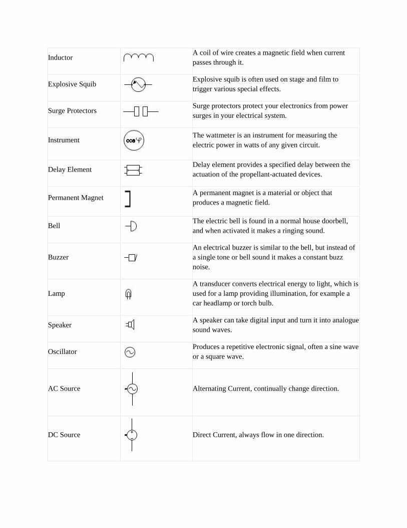
InductorA coil of wire creates a magnetic field when currentpasses through it.
Explosive SquibExplosive squib is often used on stage and film totrigger various special effects.
Surge ProtectorsSurge protectors protect your electronics from powersurges in your electrical system.
InstrumentThe wattmeter is an instrument for measuring theelectric power in watts of any given circuit.
Delay ElementDelay element provides a specified delay between theactuation of the propellant-actuated devices.
Permanent MagnetA permanent magnet is a material or object thatproduces a magnetic field.
BellThe electric bell is found in a normal house doorbell,and when activated it makes a ringing sound.
BuzzerAn electrical buzzer is similar to the bell, but instead ofa single tone or bell sound it makes a constant buzznoise.
LampA transducer converts electrical energy to light, which isused for a lamp providing illumination, for example acar headlamp or torch bulb.
SpeakerA speaker can take digital input and turn it into analoguesound waves.
OscillatorProduces a repetitive electronic signal, often a sine waveor a square wave.
AC Source Alternating Current, continually change direction.
DC Source Direct Current, always flow in one direction.

CIVIL ENGINEERING SANITARY FITTING SYMBOLSCIVIL ENGINEERING SANITARY FITTING SYMBOLSCIVIL ENGINEERING SANITARY FITTING SYMBOLS

CHAPTER-8
DEVELOPMENT OF SURFACES
The development of surface of an object means the unrolling and unfolding of allsurfaces of the object on a plane.
If the surface of a solid is laid out on a plain surface, the shape thus obtained iscalled the development of that solid.
METHODS OF DEVELOPMENT
Parallel-Line Method
It is used for developing prisms and single curved surfaces like cylinders, in whichall the edges/generation of lateral surfaces are parallel in each other.
Radial-line Method
It is employed for pyramids and single curved surfaces like cones in which theapex is taken as centre and the slant edge or generator as radius of its development.
Triangulation Method
It is used for developing transition pieces.
Approximate Method
It is employed for double curved surfaces like spheres, as they are theoretically notpossible to develop. The surface of the sphere is developed by approximatemethod. When the surface is cut by a series of cutting planes, the cut surfaces iscalled a zone.

CHAPTER-9
DETAILED AND ASSEMBLY DRAWING
A detailed drawing is a production drawing, furnishing complete information forthe construction or manufacturing of various parts.
This information may be classified as:
1. Shape description
This refers to the selection of number of views to describe the shape of the part.The part may be drawn in either pictorial or orthographic projection. Sectionalviews, auxiliary views and enlarged detailed views may be added to the drawing inorder to provide a clear image of the part.
2. Size description
Size and location of the shape features are shown by proper dimensioning. Themanufacturing process will influence the selection of some dimensions, such asdatum feature, tolerances, etc.
3. Specifications
This includes special notes, material, heat treatment, finish, general tolerances andnumber required.
4. Additional information
Information such as drawing number, scale, method of projection, date, names ofthe parts, etc., come under additional information which is included in the titleblock.
WORKING ASSEMBLY DRAWING
It is usually made for simple machines or jobs, consisting of a relatively smallernumber of simple parts. All the dimensions and information necessary for themanufacture of a part and for the assembly of the parts are given directly on theassembly drawing. Separate views of specific parts, in enlargement, showing themating of parts, may also be drawn, in addition to the regular assembly drawings.

CHAPTER-10
SCREW THREADS
Screw threads are used in fasteners such as bolts and screws, and also to provide alinear motion drive which may transmit power. There are several different types ofscrew thread used for different purposes.
Threads are applied to many devices for various purposes such as
1. It is used to transmit power.
2. It increases the efficiency of the applied effort.
3. It controls movement in a micrometer.
4. It holds parts together as in the case of fastening.

Description of Terms
1. Root
It is the bottom portion of the surface of a thread which joins the sides of theadjacent threads.
2. Crest
It is the top portion of the surface of a thread which joins the sides of the samethreads.
3. Flank
It is the surface of a thread that connects the crest with the root.
4. Angle of the Thread
It is the angle included between the sides of the two adjacent threads and measuredon an axial plane.
5. Depth of the Thread
It is the distance between the crest and the root of a thread which is measurednormal to the axis on an axial plane.
6. Nominal Diameter
It is the diameter of the cylindrical rod on which the threads are cut. This diameterspecifies the size of the screw.
7. Major Diameter
It is the diameter of an imaginary coaxial cylinder which bounds the crest of anexternal thread or the roots of an internal thread.
8. Minor, or Core, or Root Diameter
It is the diameter of an imaginary coaxial cylinder which bounds the roots of anexternal thread or the crests of an internal thread.

9. Pitch Diameter
It is the diameter of the thread at which an imaginary coaxial cylinder that can bepassed so as to cut the thread so that the width will be equal to the width of thegroove.
10. Pitch
It is the distance from a point on a screw thread to the corresponding point on thenext thread, measured parallel to the axis.
11. Lead
It is the axial distance advanced by a nut for its one full turn over a threaded rod.
On a single start thread, the lead and the pitch are identical.
On a double start thread, the lead is twice the pitch
On a triple start thread, the lead is three times the pitch.
Thus, the lead may also be defined as the product of the pitch and number of starts.
TYPES OF THREAD
V-THREADThe Bureau of Indian Standards has adopted V-thread profile recommended by theInternational Organization for Standards, ISO, a metric screw thread for use in ourcountry. These types of screw threads are also known as Unified Thread. It hasa 60° thread angle.

SQUARE THREAD
Since these types of screw threads are in the form of a square, it is called Squarethread. The flanks or the sides of this thread are perpendicular to the axis of thethread. The depth and thickness of the thread are equal to half the pitch.
ACME THREAD
This thread is the modified form of a square thread. Unlike the square thread, it iseasier to cut and stronger at the root. The angle of the thread is 29°.
SINGLE AND MULTI-THREADS
In a piece of work, it is possible to have several separate and independent threadsrunning along with it. Accordingly, there are a single threaded screw and multipleor multi-start threaded screw.
The independent threads are called starts, and we may have single-start, two-start,three-start, etc.
SINGLE THREADED SCREW
For one complete turn round the screw or bolt then there is a movement of onethread the screw is called single threaded screw.
MULTI-START THREADED SCREWS
There is a movement of more than one thread, the screw is called multiple ormulti-start threaded screws.
In the case of a three-start thread, for one complete turn, the thread advances threetimes as far if it were a single thread. Multi-start threads are used in those caseswhere rapid movement or motion is required.
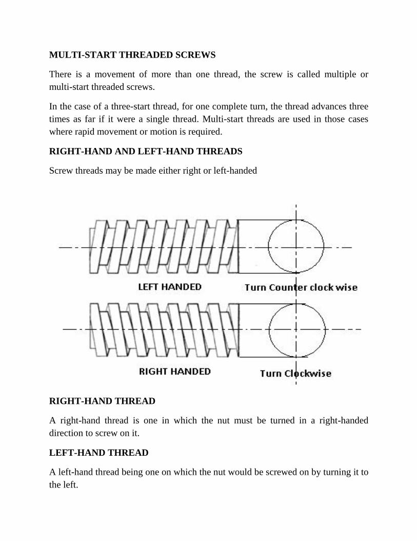
RIGHT-HAND AND LEFT-HAND THREADS
Screw threads may be made either right or left-handed
RIGHT-HAND THREAD
A right-hand thread is one in which the nut must be turned in a right-handeddirection to screw on it.
LEFT-HAND THREAD
A left-hand thread being one on which the nut would be screwed on by turning it tothe left.
MULTI-START THREADED SCREWS
There is a movement of more than one thread, the screw is called multiple ormulti-start threaded screws.
In the case of a three-start thread, for one complete turn, the thread advances threetimes as far if it were a single thread. Multi-start threads are used in those caseswhere rapid movement or motion is required.
RIGHT-HAND AND LEFT-HAND THREADS
Screw threads may be made either right or left-handed
RIGHT-HAND THREAD
A right-hand thread is one in which the nut must be turned in a right-handeddirection to screw on it.
LEFT-HAND THREAD
A left-hand thread being one on which the nut would be screwed on by turning it tothe left.

NUTS
The bolt and nut joint or screwed fastening is a temporary joint. A bolt is used tojoin two assembled parts with the help of a mating part, the nut. A screw is used tojoin two parts by making its own thread in the joining part while screwing itself.Anut is an internally threaded component joined to the externally threadedbolt.
BOLT
A bolt and nut in combination is a fastening device used to hold two parts together.The body of the bolt, called shank is cylindrical in form, the head; square orhexagonal in shape, is formed by forging.
FOUNDATIONS BOLTS
Foundation bolts are used for fixing machines to their foundations. Foundationbolts are made by forging from mild steel or wrought iron rods. The bolt sizedepends upon the size of the machine and the magnitude of the forces that act onthem when the machine is in operation.
RAG BOLT
This bolt consists of a tapered body, square or rectangular in cross-section, thetapered edges being grooved. A rag foundation bolt is set first in lead and then incement concrete.
LEWIS BOLT
It is a removable foundation bolt. The body of the bolt is tapered in width on oneside. To use this bolt, a pit is produced in cement concrete, by using a foundationblock. Once the concrete sets-in, the bolt is placed in it so that the tapered boltsurface, bears against the tapered face of the pit. A key is then inserted, bearingagainst the straight surfaces of the pit and the bolt. This arrangement makes thebolt firm in the bed. However, the bolt may be removed by withdrawing the key
EYE BOLT
This is the simplest form of all foundation bolts. In this, one end of the bolt isforged into an eye and a cross piece is fixed in it.

CHAPTER-11
KEYS AND COTTERS
A key is employed to connect two pieces, like shaft and a gear, in such a way thatthere is no relative rotational movement between the shaft and the parts mountedon it. Key is always made of steel because it is subjected to shearing and torsionalstresses. It is inserted in the axial direction between the shaft and the boss or hub ofthe mating piece. A keyway is the groove cut in the shaft as well as in the hub, toaccommodate the key.
Keys may be classified as follows:
(i) Taper keys and (ii) parallel or feather keys.
(i)Taper keys
It is tapered (standard taper of this key is 1 in 100) in thickness but uniform inwidth. A taper key joint prevents relative rotational as well as axial movementbetween the two pieces. The types of taper keys are;
(1) Sunk taper key
It is a standard form of key and may be either of square or rectangular cross-sections. Half part of its nominal thickness is sunk in the shaft key way and theremaining half portion fits in the keyway inside the hub of the mating piece.
(2) Saddle keys
They are also made in two forms i.e. hollow and flat. A hollow saddle key has itsunderside hollow to fit the curved surface of the shaft.
(3)Round key (pin key)
It is of circular cross-section, usually tapered along the length and is inserted in ahole drilled partly in the shaft and partly in the hub of mating piece.
(4) Gib-head
It is a taper key is usually provided with a head, called a gib-head, to facilitate itsremoval.

(ii) Parallel or feather keys
When there is a requirement of sliding or axial movement of mating piece on theshaft, a feather key is used. It is a sunk key of uniform width and thickness. It maybe of various cross sections like rectangular, square or dove-tail. This key may besecured to either the shaft by means of two cap-screws, having countersunk headsor the mating piece and free to slide in the keyways in the shaft. These keys arealso classified as peg feather key, single headed and double headed feather key.
WOODRUF KEY
It is a sunk key in the form of a segmental part of a circular disc having uniformthickness. It is inserted into a corresponding form of a circular keyway cut in theshaft so that the some portion projects outside.
COTTER JOINTS
A cotter is a flat wedge-shaped piece of rectangular cross section and made ofsteel. It is used to connect two rods rigidly subjected to compressive or tensileforces and is inserted at 90 0 to the axes of the rods. It is tapering in width,generally on one side only but uniform in thickness. The bearing edge of the cotterand the bearing slots are generally made semicircular. This joint is not suitable forconnecting the rotating members.
VARIOUS TYPES OF JOINTS The most commonly used types of cotter jointsare
SPIGOT AND SOCKET JOINTS
A spigot joint is a type of pipe fitting connection that is inserted into another pipefitting. The spigot end typically has the same outer diameter as the pipe and isusually fitted into another joint called a bell or socket.

GIB AND COTTER JOINT
A gib and cotter joint is usually used in strap end (or big end) of a connecting rodIn such cases, when the cotter alone (i.e. without gib) is driven, the frictionbetween its ends and the inside of the slots in the strap tends to cause the sides ofthe strap to spring open (or spread) outwards.
In order to prevent this, gib are used which hold together the ends of the strap.
KNUCKLE JOINT
A knuckle joint is a mechanical joint used to connect two rods which are undera tensile load, when there is a requirement of small amount of flexibility, orangular moment is necessary. There is always axial or linear line of action of load.The knuckle joint assembly consists of the following major components:
1. Single eye.
2. Double eye or fork
3. Knuckle pin.

APPLICATIONS
1. Tie rod joint of roof truss.2. Tension link in bridge structure.3. Link of roller chain.4. Tie rod joint of jib crane.5. The knuckle joint is also used in tractor.

CHAPTER-12
INTRODUCTION TO COUPLING
A coupling is a device used to connect two shafts together at their ends for thepurpose of transmitting power. The primary purpose of couplings is to join twopieces of rotating equipment while permitting some degree of misalignment or endmovement or both.
USES
Shaft couplings are used in machinery for several purposes. A primary function isto transfer power from one end to another end (ex: motor transfer power to pumpthrough coupling).
USES
To provide protection
To connect driving and the driven part
To reduce the transmission of shock loads from one shaft to another
TYPES
MUFF COUPLING
It is the simplest form of rigid coupling, consists of a hollow cylinder whose innerdiameter is same as shaft. It is fitted over the ends of the two shafts by means ofgib head key. The power is transmitted from one shaft to the other shaft by meansof a key and a sleeve or muff.

FLANGE COUPLING (PROTECTED)
Flange Coupling is a type of connector between rotating flanges that have two setsof flanges. One of these flanges is immobile at the end of each shaft. To completethe process of transferring power, both the flanges are fastened together with manynuts and screws.

FLEXIBLE COUPLING
The function of a flexible coupling is to transmit torque from the driver to thedriven machine while making allowances for minor shaft misalignment and shaftend position changes between the two machines.
Shaft misalignment exists when the centerlines of two shafts joined by a couplingdo not coincide.
Fig. shows the various types of misalignment and shaft end position changes thatcan occur.