e-perm alpha surface monitor - digital library/67531/metadc709292/...bmmvame \/ . 1? doe/em-xxxx...
TRANSCRIPT

WSRC-TR-99-00460
E-Perm Alpha Surface Monitor.
by
V. Fricke
Westinghouse Savannah River CompanySavannah River SiteAiken, South Carolina 29808
C. Mayo
S. Salaymeh
DOE Contract No. DE-AC09-96SR18500
This paper was prepared in connection with work done under the above contract number with the U. S.Department of Energy. By acceptance of this paper, the publisher ancf/or recipient acknowledges the U. S.Government’s right to retain a nonexclusive, royalty-free license in and to any copyright covering this paper, alongwith the right to reproduce and to authorize others to reproduce all or part of the copyrighted paper.

BmmvAmE.\/
1? DOE/EM-XXXX
Summary RepoiT
I
E-PERM@Alpha SurfaceMonitor
Deactivation and Decommissioning Focus Area
Prepared for
U.S. Depar~ment of EnergyOffice of Environmental Management
Office of Science and Technology
December, 1999
WSRC-TR-99-O0460
—
DISCLAIMER
This report was prepared as :an account of work sponsored by an agency of the United StatesGovernment Neither the United States Government nor any agency thereof, nor any of theiremp!oyees, makes any warranty, express or implied, or assumes any legal liability or responsibilityfor the accuracy, completeness, or usefulness of any information, apparatus, product or processdisclosed, or represents that its use would not infringe privateIy owned rights. Reference herein toany specific commercial product process or service by trade name, trademark, manufacturer, orotherwise does not necessarily constitute or imply its endorsement recommendation, or favoringby the United States Government or any agency thereof. The views and opinions of authorsexpressed herein do not necessarily state or reflect th”oseof the United States Government or anyagency thereof.
This report has been reproduced directly from the best available copy.
Available for sale to the public, in paper, from: U.S. Department of Commerce, National Technic+Information Service, 5285 Port Royal Roa& Springfield, VA 22161, phone: (800) 553-6847fax: (703) 605-6900email: orders@ ntis.fedworld.govonline ordering: http:hww.ntis.govlordering.htm.
AvaiIable electronically at http:hww.doe.govlbridgeAvailable for a processing fee to U.S. Department of Energy and its contractors, in paper, from:U.S. Department of Energy, Office of Scientific and Technical Information, P.O. Box 62, OakRidge, TN 37831-0062, phone: (865) 576-8401fax: (865) 576-5728email: reports @adonis.osti.gov
.— — ——
WSRC-TR-99-O0460
. ... ,,, . . . .. .... . .— .--. ——..

DISCLAIMER
Portions of this document may be illegiblein electronic image products. Images areproduced from the best available originaldocument.
.--- .-,..-m - .,:7--7. ,. ... , , ,..:-. .-. m--?’-.: ..mnzw-’m%c-?- ,T ---- T-. ..7;.. -.7-7 :.--.-.%..
.- ---T?rsxTz—=7-mGlr-7----- - - ,-.77-=- --- --.: -,-r ------
E-PERM@ Passive Electret[on Chamber
OST Reference # 2315
Deactivation and DecommissioningFocus Area
Demonstrated at321-M Fuel Fabrication Facility
Large-Scale Demonstration and Deployment ProjectSavannah River Site
Aiken, South Carolina
WSRC-TR-99-O0460

WSRC-TR-99-O0460
Summary Report
Purpose of this document
Innovative Technology Summary Reports are designed to provide potential users with theinformation they need to quickly determine if a technology would apply to a particularenvironmental management problem. They are also designed for readers who may recommendthat a technology be considered by prospective users.
Each report describes a technology, system, or process that has been developed and tested withfunding from DOE’s Office of Science and Technology (OST). A report presents the full range ofproblems that a technology, system, or process will address and its advantages to the DOEcleanup in terms of system performance, cost, and cleanup effectiveness. Most reports includecomparisons to baseline technologies as well as other competing technologies. Information about -commercial availability and technology readiness for implementation is also included. InnovativeTechnology Summary Reports are intended to provide summary information. References formore detailed information are provided in an appendix.
Efforts have been made to provide key data describing the performance, cost, and regulatoryacceptance of the technology. If this information was not available at the time of publication, theomission is noted.
All published Innovative Technology Summary Reports are available on the OST web site athttp://OST.em.doe. gov under “Publications.”
WSRC-TR-99-O0460

EBSUMMARY
H TECHNOLOGY DESCRIPTION
❑ PERFORMANCE
❑‘ TECHNOLOGY APPLICABILITY AN”D
ALTERNATIVES
H COST
❑c REGULATORY AND POLICY ISSUES
❑ LESSONS LEARNED
APPENDICES
❑A References
13Dw
H
Technology Cost Comparison
Acronyms and Abbreviations
WSRC-TR-99-O0460
1
5
8
11
13
17
18
19
20
xx

SECTION 1
i
The E-PERM@ Alpha Surface Monitor is an integrating electret ion chamber innovative technologyused to measure alpha radiation on surfaces of materials. The technology is best used onsurfaces with low contamination levels such as areas with potential for free release, but can alsobe used in areas with higher levels of contamination. Measurement accuracy and production ofthe E-PERM@ Alpha Surface Monitor compared favorably with the baseline technology. Theinnovative technology cost is approximately 38% higher than the baseline with an average unitcost per reading costing $6.04 vs. $4.36; however, the flexibility of the E-PERM@ Al~ha SurfaceMonitor may offer advantages in ALARA, reduction of operato~error, waste minimi~ation, andmeasurement accuracy.
■ Technology Summary
The E-PERM@ Alpha Surface Monitor is a small, stand alone, integrating electret ion chamber(EIC) used to measure alpha radiation on surfaces of materials. The system is composed of asmall ion chamber with a mylar window to contain the ions produced by the interaction of alpharadiation with air and a sensor to collect and measure the ions produced. A separatemicroprocessor provides the hardware to measure and process data.
Problem b
Many Department of Energy sites have a need to quickly and cheaply characterize surfaces foruranium, plutonium, and other alpha emitting radionuclides. A method that minimizes waste,reduces personnel exposure, and reduces costs is needed to efficiently characterize excessfacilities.
How It Works
When ionizing alpha radiation from a contaminated surface enters an electret ion chamber, theradiation causes ionization by stripping electrons from atoms of air in the chamber. The ejectedelectrons are attracted to a positively charged piece of Teflon”, called the electret, mountedinside an ion chamber. The electrons collect on the surface of the electret and neutralize itscharge. After the designated exposure time has elapsed, the electret is removed from thechamber. Using a portable charge reader, the electret’s final voltage is read. The difference inthe electret’s initial and final voltages is a function of exposure time and the alpha contaminationlevel to which the chamber has been exposed. After the charge reader measures the change inthe electret’s voltage, this data is used to calculate the contamination level. Data can bedownloaded to a personal computer to provide databases and aid in reporting.
Potential Markets
a-,i~t U. S. Department of Energy WSRC-TR-99-O0460 1
In addition to SRS, Oak Ridge National Laboratory, Rocky Flats, Fernald, the Nevada Test Site,Hanford, and the Tonopah Test Range have the need to characterize surfaces with alphaproducing radionuclides.

Figure 1. SPER2 Microprocessor, electret, and 180 cm2 ion chamber.
Advantages Over the Baseline
The baseline technology is the hand probe and smear method. The advantages of the E-PERM@Alpha Surface Monitor are:
●
●
●
●
●
●
Simple to use and analyze. Semiskilled technician sufficient.
Small size and weight. Units can be easily located in difficult-to-reach areas. Units can beplaced on floors, walls, and ceilings.
Minimizes personnel exposure. Units can be set in position and left until exposure time iscomplete. Technician does not stay in radiation area during survey.
Eliminates operator error and fatigue.
Microprocessor collects, stores, and analyzes data to make repotting easier and quicker.
Robust technology. The electrets are unaffected by shock, humidity, and temperature.
Limitations of Technology
Surfaces where the EICS are placed should be relatively flat and smooth to form an enclosedspace with the EIC. Gaps between the EIC and surface being monitored may cause erroneousreadings.
@
Ji j ~ U.S. Department of Energy WSRC-TR-99-O0460 2
. .—,.-- . .— ----- . .

Demonstration Summary
The E-PERMQ Alpha Surface Monitor demonstration was held in the 321-M Fuel FabricationFacility located at the Savannah River Site (SRS) during the period June 16, 1999 to August 24,1999. The 321 -M facility was used to manufacture fuel and target assemblies for irradiation in thesite production reactors. The facility was de-inventoried in 1995, leaving the process area a highcontamination area, contaminated with highly enriched uranium. Other parts of the buildingremain posted radiological areas with lower levels of contamination. Some overhead areas havelow level contamination. During deactivation of the facility, surveys are necessary to establish thecontamination levels in the facility.
Key Results
The key results of the innovative technology demonstration are:
. Measurements with the EICS showed satisfactory agreement with the baseline technologyand NIST traceable standards.
. Productivity was approximately the same as the baseline; however, productivity shouldincrease in surveys with large numbers of readings.
. The cost of performing characterization work with the EICS is higher on the average than thebaseline.
. In addition to those advantages listed above, there is no radioactive waste produced andmeasurement accuracy can be improved with longer exposure times if necessary.
. The EICS are most efficient in areas where access with the baseline technology is difficult orlimited (e.g., overheads, gloveboxes) and for final surveys using the MARSSIM guidelines.
Regulatory/Policy Issues
None
Availability
The E-PERM@ Alpha Surface Monitor is available from Rad Elec Inc.
Future Plans
The E-PERM@ Alpha Surface Monitor technology will become an alternative to the hand probeand smear method of characterization at SRS. The technology may be used when technologycapabilities meet job requirements and objectives.
Contacts
Technical
Jeffrey Lee, Westinghouse Savannah River Company, (803) 725-0652; jeffrevw.lee@srs. aovCecil May, Savannah River Technology Center, (803) 725-581 3; [email protected] Salaymeh, Savannah River Technology Center, (803) 725-1628;saleem.salaVmeh @?srs.uovVito Casella, Savannah River Technology Center, (803) 725-1302; vito.casella@srs. aovLorin Stieff, Rad Elect Inc., (301) 949-9508; lstieff@aoLcom
@
.. .1J
U.S. Department of Energy WSRC-TR-99-O0460 3

Management
Cecil May, Test Engineer, Westinghouse Savannah River Company, (803) 725-5813,[email protected] Pierpoint, Project Manager, Westinghouse Savannah River Company, (803) 725-0649,john.~ierpoint@ srs.qov
321-M Large-Scale Demonstration and Deployment Project
Martin Salazar, U.S. Department of Energy, Savannah River Operations Office; (803) 557-3617;martin. [email protected] Mishra, U.S. Department of Energy, Savannah River Operations Office; (803) 725-7239;qeorcie.mishra@ srs.qov
John Duda, Federal Energy Technology Center, (304) 285-4217, [email protected]
Licensing Information
No licensing or permitting activities were required to support this demonstration,
Web Site
The 321-M LSDDP Internet address is httW/www.srs.qov/qeneral/srtech/lstd/index.htm
Other
All published Innovative Technology Summary Reports are available online at http://em-50.em.doe.gov. The Technology Management System, also available through the EM50 Website, provides information about OST programs, technologies, and problems. The OST Reference#for the E-PERM@ Alpha Surface Monitor technology is 2315.
@
e,
i ~t U.S. Department of Energy WSRC-TR-99-O0460 4

SECTION 2 .
Overall Process Definition
The E-PERM@ alpha monitor is a small, stand alone, integrating electret ionization chamber(EIC). The E-PERM@ alpha monitor consists of:
● An electret● The ion chamber housing● A portable electret voltage reader
When ionizing alpha radiation from a contaminated surface enters the ion chamber through a thinaluminized mylar window, the radiation causes ionization by stripping electrons from atoms of airin the chamber. The ejected electrons are attracted to the electret mounted inside the ionchamber. The electrons collect on the surface of the electret and overtime partially neutralize theinitial charge.
After the designated exposure time has elapsed, the electret is removed from the chamber and itsfinal voltage is measured using an electret charge reader. The difference in the electret’s initialand final voltages is a function of the alpha contamination level it has been exposed to and thetime of the exposure. The voltage drop and exposure time are converted to contamination levelsby either a hand-held computer or a microprocessor reader that can provide immediatecontamination levels in dpm/100 cm2.
E/ectret
The electret is a positively charged Teflon@ disc that serves as both the source of an electrostaticfield and a sensor. The electrets are very stable and are unaffected by shock, humidity,temperature, and will hold charges for long period of times if not exposed to ionizing radiation.The electret is available in the following thicknesses and sensitivities:
● 0.127 mm (long-term exposure, low sensitivity). 1.524 mm (standard sensitivity). 4.572 mm (short-term exposure, high sensitivity)
Each electret can be used for multiple measurements. The number of measurements dependson the voltage drop for each measurement. Each electret has an initial charge of approximately700 volts and can be used down to approximately 200 volts. Acceptable readings can be madewith a minimum drop of 15-20 volts. During the demonstration, a 30-volt drop gave accuratemeasurements. In general, the higher the voltage drop, the better the accuracy. Once theelectret has been discharged, it cannot be recharged and must be discarded.
Ion Chamber
The ion chamber provides a holder for the electret and a chamber for containing the ionsproduced by the alpha radiation. Ion chambers are available in two sizes: 1)48 cm2, and 2) 180cmz. The chambers are made of electrically conducting plastic and have windows covered with athin aluminized mylar film to protect the electret from dust and other particles. Other materialsmay be used as window covers for background measurements and measurements of otherradionuclides.
@
*,i ~f U.S. Department of Energy WSRC-TR-99-O0460 5

Electret Voltage Reader
There are two electret voltage readersavailable. A hand held reader, called theSPERI is suitable for relatively small numbersof electret measurements. It is easily protectedfrom contamination in contaminated areas.The voltage readings, electret serial numbers,locations, deployment times, and radiationlevels must be manually recorded andcalculated.
The SPER2 Microprocessor Electret Reader isdesigned to manage data associated with largenumbers of measurements. The reader iscombined with a barcode reader and computerhardware that stores measurement data. Thedata can be downloaded to a personalcomputer (PC) to calculate radiation levels andcreate databases and reports. The unit ispackaged in a rugged case and can be used inthe field for onsite measurement. [t is notrecommended to take the unit into highlycontaminated areas.
Goals and Objectives
-w- —=’ ““”-’””:”?~”-——’” -~.- —- ----- ..” . -- .~.
\
. .’7. ,. ..,– .._ ~-u-”;:;~-l
~ {~,.—~.y-. — .
k .. — .;
-.,, .-$vky: -... - - - ------
.—
Figure 2. SPER2 Microprocessor, electret,and 48 cm2 ion chambers
The goals and objectives of the E-PERM@ demonstration were to:
. locate and quantify HEU contamination in selected areas in 321 M● compare and evaluate against the baseline hand probe and smear surveys● provide sufficient data for deployment at SRS and within the DOE complex
The E-PERM@ technology has potential for use at any DOE facility that has alpha contaminatedsurfaces.
System Operation
The E-PERM@ EIC is a passive detector that requires no external electrical power or batteries.The ionization chambers, with electrets installed, are small, lightweight chambers that can beeasily affixed to most flat surfaces. The 48 cm2 ionization chambers are approximately 1 5/8 in.(4 cm) highby31/4 in. (8 cm) in diameter. The 180 cm2chambers are approximately 3 1/4 in. (8cm) high by 7 5/1 6 in. (19 cm) in diameter. The chambers and electrets weigh only 6 to 8ounces.
Atypical sequence of activities to measure alpha contaminated surfaces is as follows:
1.
2.
Make initial electret voltage readings using SPER2 data logging reader and barcode reader.This initial reading records the electret serial number, location, initial voltage, and initial time.The time can also be manually entered to accurately record the electret placement time.
Load electrets into the ion chambers.
@
* J
i ~r U.S. Department of Energy WSRC-TR-99-O0460 6

3.
4.
5.
6.
7.
Determine approximate exposure time and deploy detectors at selected locations. Recordelectret serial number and location. Exposure times will depend on the radiation level. A fewhours will be sufficient in areas with higher radiation levels. For very low levels, overnightexposures may be used. In these cases, the detectors maybe deployed in the afternoon andremoved the next morning.
After exposure time has elapsed, collect detectors. Electrets should either be removed fromthe ion chambers or covers placed on the chambers to prevent additional exposure of theelectret.
Make final electret voltage readings using SPER2 data logging reader and barcode reader.The final reading provides the final voltage readings and times required to compute theradiation levels.
Connect the SPER2 reader to a PC and download data for reporting purposes.
For every 10 detectors deployed, one beta/gamma background detector should be deployedand anajyzed the same way as the other d~ectors. -
. .
Figure 3. Electret Ion Chamber placed in Tube Cleaning Room
Manpower Skills and Training Requirements
The EICS and SPER2 microprocessor are simple and easy to use and require no special operatortraining. A short orientation session given by the manufacturer and lasting approximately twohours is normally required.
Secondary Waste
The electrets do not normally come in contact with contaminated surfaces. Spent electrets wouldnormally be clean waste. The ion chambers maybe contaminated on the external surfaces incontact with contamination. The chambers are not contamination resistant and may bedecontaminated if necessary. If decontamination is not possible, the ion chambers may becomelow level waste. There is no hazardous waste created by the technology.
m+,i ~r U.S. Department of Energy WSRC-TR-99-O0460 7
.
_. ——._ ._.
SECTION 3
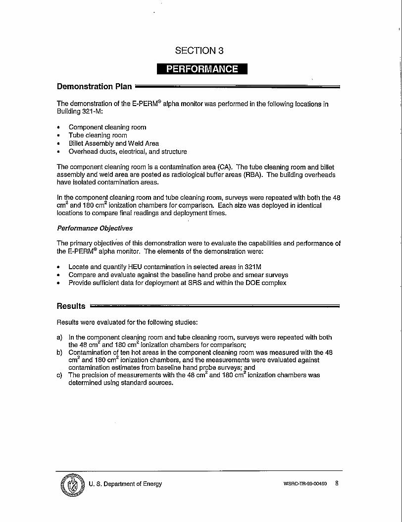
Demonstration Plan
The demonstration of the E-PERM@ alpha monitor was performed in the following locations inBuilding 321-M:
. Component cleaning room
. Tube cleaning room
. Billet Assembly and Weld Area
. Overhead ducts, electrical, and structure
The component cleaning room is a contamination area (CA). The tube cleaning room and billetassembly and weld area are posted as radiological buffer areas (RBA). The building overheadshave isolated contamination areas.
In the component cleaning room and tube cleaning room, surveys were repeated with both the 48cmz and 180 cm2 ionization chambers for comparison. Each size was deployed in identicallocations to compare final readings and deployment times.
Performance Objectives
The primary objectives of this demonstration were to evaluate the capabilities and performance ofthe
●
●
●
E-PERM@ alpha monitor. The elements of the demonstration were:
Locate and quantify HEU contamination in selected areas in 321 MCompare and evaluate against the baseline hand probe and smear surveysProvide sufficient data for deployment at SRS and within the DOE complex
Results
Results were evaluated for the following studies:
a)
b)
c)
In the component cleaning room and tube cleaning room, surveys were repeated with boththe 48 cm2 and 180 cm2 ionization chambers for comparison;Contamination of ten hot areas in the component cleaning room was measured with the 48cm2 and 180 cm2 ionization chambers, and the measurements were evaluated againstcontamination estimates from baseline hand probe surveys; andThe precision of measurements with the 48 cm2 and 180 cm2 ionization chambers wasdetermined using standard sources.
@i ~r ~ U.S. Department of Energy WSRC-TR-99-O0460 8

,.
Figure 4. Positioning of Large ChamberEICS in Component Cleaning Room.
Alpha measurements were performed withboth the 48 cm2 and 180 cm2 ionizationchambers in the component cleaning roomand tube cleaning room. Each size wasdeployed at the same locations to comparefinal readings and deployment times. Twenty-five chambers and three backgroundchambers of each size were used to measuretwenty-five locations in each room. Thebackground chambers contained a carboncoated Tyvek window to remove alpharadiation. The exposure time for the 48 cm2chambers was 22 hours, while the 180 cm2chambers were exposed for 6 hours.
A comparison of results for the small and large electret ionization chambers is shown in Table 1.Since the large chambers (LC) measured about four times the area that the small chambers (SC)measured, the results are not directly comparable. Both chambers verified that the contaminationwas below 100 dpm alpha/100 cm2 for forty-six of these areas. Also, both chambers measuredthe contamination levels for four of the areas to be above 100 dpm alphall 00 cm2 with agreementto within a factor of two (SC/LC = 1.5). This agreement is considered acceptable, since differentareas of the same location are being measured..
Table 1. Comparison of Large Chamber (LC) and Small Chamber (SC) EIC Results for theComponent Cleaning Room (CCR) and Tube Cleaning Room (TCR)
Average Average SC/LC AverageArea Surveyed Results SC Results LC Data (4)>100 Probe Surve
(dpm/100cm2) (dpm/100cm2) dptil OOcm2 (dprrdl OOcm{
CCR (25 low alpha locations) 77 73 1.5TCR (25 low alpha locations) 11 13CCR (1Ohot areas) 654 780 724
Contamination of ten hot areas in the component cleaning room was measured with the 48 cm2and 180 cm2 ionization chambers? and the measurements were evaluated against contaminationestimates from baseline hand probe surveys. Background measurements were performed at thelocations where the ambient radon and gamma radiation was high enough to contribute to theresponse of the electret ionization chambers. Again, since the large chambers measured aboutfour times the area that the small chambers measured, the results are not directly comparable.
In general, the electret ionization chamber (EIC) results showed about the same level ofcontamination as the hand probe surveys. In a few instances, the agreement between the handprobe and EIC results showed a variation greater than a factor of two, but this would be expectedsince the contamination is not uniformly distributed in these areas.
The 48 cm2 ionization chamber had advantages of a lower background and less sensitivity forhigh-level contamination measurements. However, the 180 cm2 ionization chamber hadadvantages of a shorter exposure time, a larger measurement area and was more sensitive forlow level contamination areas.
Based on duplicate measurements of NIST traceable standard alpha sources, the measurementprecision for voltage changes of about 40 volts was determined to be better than 37. for the 48cm2 chambers and better than 4’ZOfor the 180 cm2 chambers.
@
., “r ; U.S. Department of Energy. .*
WSRC-TR-99-O0460 9
Both the 48 cm2 and 180 cm2 ionization chambers were able to show that contamination wasbelow 100 dpm/100 cm2 alpha (uranium-235), and the results showed satisfactory agreementwith estimates from hand probe surveys. Results from these studies suppott the potential use ofthis technology as a method to measure alpha (U-235) surface contamination at SRS and withinthe DOE complex.
@
. .
i j U. S. Department of Energy WSRC-TR-99-O0460 10

SECTION 4
Competing Technologies
The hand probe and smear method is the baseline technology usually selected for measuringalpha contamination on material surfaces.
Hand probe and smear method disadvantages:
. Accuracy is dependent on operator technique. Probe scanning speed and distance to thesurface being scanned determine the accuracy of the method. Sensitivity decreasesmarkedly when scan speed and distance is increased.
● Probing of large surface areas may become tedious and prone to operator error. Accuracymay decline after several hours of surveying.
. The alpha scintillation detectors used in hand probing are fragile. The mylar window is easilypunctured and requires replacement. Calibration and maintenance are routine tasks.
. Hand probe and smear is a slow process requiring manpower to scan, count smears, andwrite reports.
Technology Applicability
The E-PERM@ EIC technology addresses the disadvantages of the baseline technology. The EICeliminates the potential inaccuracies caused by operator technique and has potential for reducingthe overall manhours required for the surveying process. Since the EICS are passive detectors,they can be placed in position and left until the monitoring time is complete. An operator does notremain in the area and is free to perform other work. Data is stored in the SPER2 microprocessorduring the initial and final voltage readings. The data can be downloaded to a PC and used toreduce the manhours required to manually create final survey reports. Additional advantages andbenefits of the EICS are shown in Table 2.
Measurement applications include:
. Measurement of contaminated surfaces and swipes
. Qualifying measurements for free release of contaminated sites
. Secondary verification of other monitoring systems
. Ideal for monitoring large areas using the Multi-Agency Radiation Survey and SiteInvestigation Manual (MARSSIM) guidelines
@i j U.S. Department of Energy WSRC-TR-99-O0460 11
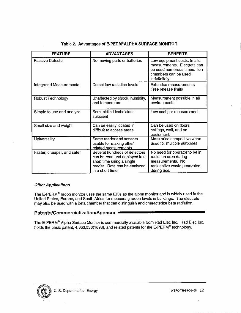
Table 2. Advantages of E-PERM@ALPHA SURFACE MONITOR
FEATURE ADVANTAGES BENEFITS
Passive Detector No moving parts or batteries Low equipment costs. In situmeasurements. Electrets canbe used numerous times. Ionchambers can be usedindefinitely.
Integrated Measurements Detect low radiation levels Extended measurementsFree release limits
Robust Technology Unaffected by shock, humidity, Measurement possible in alland temperature environments
Simple to use and analyze Semi-skilled technicians Low cost per measurementsufficient
Small size and weight Can be easily located in Can be used on floors,difficult to access areas ceilings, wall, and on
ewment.Universality Same reader and sensors More price competitive when
usable for making other used for multiple purposesrelated me~urements
Faster, cheaper, and safer Several hundreds of detectors No need for operator to be incan be read and deployed in a radiation area duringshort time using a single measurements. Noreader. Data can be analyzed radioactive waste generatedin a short time during use.
Other Applications
The E-PERM” radon monitor uses the same EICS as the alpha monitor and is widely used in theUnited States, Europe, and South Africa for measuring radon levels in buildings. The electretsmay also be used with a beta chamber that can distinguish and characterize beta radiation.
Patents/Commercialization/Sponsor
The E-PERM@ Alpha Surface Monitor is commercially available from Rad Elec Inc. Rad Elec Inc.holds the basic patent, 4,853,536(1 898), and related patents for the E-PERM@ technology.
Q?,ij i U.S. Department of Energy WSRC-TR-99-O0460 12
..

SECTION 5
Introduction / Methodology
This cost analysis compares the innovative E-PERM@ Alpha Surface Monitor technology with thebaseline probe and smear technology. These two comparable technologies characterize andmeasure contamination levels. Both technologies were demonstrated at DOE-Savannah RiverSite (SRS) and the data was recorded. The innovative technology uses electret ionizationchambers (EIC) and an electret reader. The baseline technology uses a hand probe and swipe ofthe surface to determine contamination levels.
The cost analysis was based on recorded data performance of both innovative and baselinetechnologies. This analysis presents realistic estimates that represent actual characterizationwork within SRS. The site demonstration of the innovative technology was based on datarecorded by the EIC. The data was collected on site during the Large Scale Demonstration andDeployment Project (LSDDP) at building 321-M. Descriptions contained in later portions of thisanalysis detail any changes to the observed data.
The cost analysis compares the two characterization technologies: an innovative E-PERM@technology and a conventional characterization method using the probe and smear method. Costand performance data was collected for each technology during their respective demonstrations.The following cost elements were identified from the Hazardous, Toxic and Radioactive WasteRemedial Action Work Breakdown Structure NVBS) and Data Dictionary (HTRW RA WBS), USArmy Corps of Engineers. Data was collected to support a cost analysis based on thoseelements:
● mobilization● characterization. demobilization
Mobilization costs include the costs of initial electret readings and transporting technologyequipment to the work area. It includes any calibration and operational checks necessary forroutine use.
Characterization includes all direct and indirect activities associated with performingcharacterization work, placing and removing EICS, reading EICS, recording data, and reporting.
Demobilization includes clearing equipment from radiological areas and removal from the workarea.
Personal Protective Equipment (PPE) costs are included in this demonstration. Two sets ofPPEs are required when using EICS in contamination areas; one set to deploy the EICS, and oneset to retrieve them.
Cost Analysis
Data was collected during the demonstrations for the cost elements. Work was measured andunit costs determined on the basis of reading/measurements per hour. For each element, detailedcosts were determined from the data collected.
@
* -,i~f U.S. Department of Energy WSRC-TR-99-O0460 13

Labor rates used in the innovative technology analysis were those in effect for the SRS site laboragreement. There was no contaminated waste disposal required for this demonstration. Crewsfor the various activities were based on the recorded data. Indirect costs were omitted from theanalysis, since overhead rates can vary greatly among contractors. Engineering, qualityassurance, administrative costs and taxes were also omitted from the analysis. Adding sitespecific indirect costs to produce a site-specific unit cost that includes indirect costs can modifythe bare unit costs determined by the analysis.
Capital equipment costs for the innovative and baseline technologies are based on the cost ofownership. The cost of the ion chambers and reader is $8,730.00 with a useful life range of 5 to10 years. This report will assume a 10-year useful life. No information was collected todetermine the projected time of use per year. The following assumptions are made to assignequipment cost dollar figure to the project: 1) expected useful life of the new technologyequipment is 10 years; 2) equipment is operated 8 hours per day, 5 days a week for 50 weeks ayear. Based on these assumptions, the extended cost per hour of operation would beapproximately $0.44. The base/ine techno/ogyprobe equipment is considered as overhead costand is included in the Health Protection labor rate.
The cost of electrets depends on the number of electrets purchased and the number of timesused. For this demonstration, 56 were purchased at a costof$17.00 per electret. Each electretcan be used a number of times depending on the voltage drop of each reading. An average offifteen readings per electret was used to determine electret cost for each measurement. Thisgives an average cost of $1.13 per reading. The cost of 56 electrets was prorated based on the178 measurements taken during the demonstration.
The electret costs are based on the quantity purchased. The current unit cost ranges from$25.00 to $13.50 each. The lowest cost is based on the purchase of 500 units. Electret costs forsurveys with a large number of readings could be reduced by up to 20% depending on thenumber of electrets purchased.
The productivity for the two technologies is approximately the same, at 16 readings per houreach. The innovative technology is based on 178 EIC readings and the baseline technology isbased on 207 probe and smear readings.
The readings per hour for the EICS are based on the manhours required for the initial electretreadings, deployment, pickup, and final readings. Vendor experience shows that the number ofreadings per hour can be increased on projects with large number of readings. Manhours will bereduced with experience in using the process. Production can be significantly increased whenperforming final surveys using the MARSSIM guidelines.
A comparison of the unit cost elements is shown in Table 3. The mobilization and demobilizationcost are not included in the summary unit costs and the units are expressed in readings per hour.
Table 3. Summary Unit Cost Comparison
EPERM Probe and Smear I(lnnovativeTechnology) (Baseline Technology)
Cost Element Unit Production Cost Element Unit Production Ratecost Rate cost
Characterization $6.04 16 ReadingslHr Characterization $4.36 16 Readings JHrWork Work
@i~f U.S. Department of Energy WSRC-TR-99-O0460 14

Figure 5 is a cost comparison for the innovative and baseline technologies demonstration at SRS.Both technologies are based on the purchase of the equipment. The cost of the capitalinvestment will differ somewhat in each of the two technologies. Figure 6 is a projected costcomparison of the innovative and baseline technologies ranging from 100 to 5000 readings. Theestimated cost for both technologies are spread over their useful life.
The cost of performing the characterization work was found to be lower on the average in thebaseline technology, when the mobilization and demobilization cost were not included.
$lJOO
$1,000
‘m
$200
w-hw’ Mmikdion chamch-hation Dextdiliia+ian‘ TotalCost “
Figure 5. Estimated Cost Summary
100000
10000@-u:c)
1000
❑ InnovatkTechnoIo~, EPEEWl
EBaseline Technology,Prokwand smear
— mwRMI
— ‘Probe and Smear
100100 500 1000 5000
Readings/Counts
Figure 6. Projected Cost Comparison
ai j U.S. Department of Energy WSRC-TR-99-O0460 15

Cost Conclusions
The baseline technology does offer small cost savings over the innovative technology. The totalcost for the two comparative demonstrations are $1,193.81 (Innovative) and $1 ,022.32 (Baseline).The innovative technology is based on 178 readings. The EICS are hand carried and dispersedand retrieved. The baseline data is based on 207 readings. To give a meaningful comparisonthe innovative and baseline data are evaluated on a unit cost. This does not alter the unitproductivity. The unit costs per reading are $6.04 and $4.36 (innovative vs. baseline).
The innovative technology is approximately 38% higher than the baseline technology. Thereason for the cost difference is that there is no equipment expense shown for the baselinetechnology. The equipment cost is embedded in the hourly rate for the health protectiontechnician. The innovative technology equipment cost is arrived by assuming that each electretwill have a life of 15 readings and that a typical exposure time is one hour. The cost for theelectret reader and equipment is prorated at $0.44/Hr and electret at $1.1 3/reading. This equatesto approximately $1.57 per hour.
The innovative technology however does offers more flexibility over the baseline technology. TheEICS can be reused many times, workers do not handIes swipes, and the EICS can be left out forlonger periods to give accurate background checks/readings. There is less chance forcontamination of equipment and workers with the innovative technology.
\
.
@
~ T.; ;9 ~ U.S. Department of Energy WSRC-TR-99-O0460 16
SECTION 6
Regulatory Considerations
There are no Comprehensive Environmental Response, Compensation, and Liability Act(CERCLA) or other regulatory considerations related to this technology.
The use of this technology as an alternative to the baseline technology requires approval byresponsible site or facility health physics departments.
-—- .
-=.. ‘
I
!
1
,1
.
@
*Li~r ~ U.S. Department of Energy WSRC-TR-99-O0460 17
J
...
SECTION 7
ImplementationConsiderations
●
●
●
●
●
After the initial electret reading, the final reading of a measurement becomes the initialreading of the next measurement. If the time span between the measurements is lengthy,the electrets may lose voltage charge due to background or other radiation fields and must bere-read before using again.
During normal use, the electret may attract dust and other small particles that may causeerroneous readings. Pressurized dry air or nitrogen is recommended for removing theseparticles.
Do not touch the Teflon” surface of the electret. Touching will discharge the electret and itwill be useless.
Electret exposure times should be estimated to reduce overexposure or underexposure. Thiscan be done by estimating radiation levels from previous surveys or experience, or byperiodic electret readings after placement. The SPER1 reader is easily carried to areas ofdeployment for making periodic readings. Either way may prevent the complete discharge ofan electret and no useful data.
The EPERM technology can be used most efficiently both in areas where access with thebaseline technology ii fimited or difficult (e.g., overheads, gloveboxes), and for final surveysof areas using the MARSSIM guidelines.
Technology Limitations and Needs for Future Development
The E-PERM@ technology has potential application for measuring alpha contamination in pipesand on the surfaces of small items. A system designed to provide flowing air throughcontaminated pipe coupled with a chamber to contain the ions and hold the electret would providean inexpensive monitor. A similar system with a chamber to hold tools or small items and asecond ion chamber could do the same for small items.
The software that allows the downloading of data, stored in the SPER2 microprocessor, to a PCshould be updated and made more user friendly.
Limitations of the EIC areas follows:
. Surfaces where the EICS are placed should be relatively flat and smooth to form an enclosedspace with the EIC. Gaps between the EIC and surface being monitored may causeerroneous readings.
@
?,i if . U.S. Department of Energy WSRC-TR-99-O0460 18

APPENDIX A
Dua, S. K., P. Szerszen, R. Rose, J. Boudreaux, M. A. Ebadian, C. May, S. Salaymeh, and K.Kasper, 1999. Evaluation of Electret Ion Chambers for Measurement of Surface A~haContamination in Preparation for SRS-LSDDP. Paper presented at 2ndTopical Meeting onDecommissioning, Decontamination, & Reutilization of Commercial and GovernmentFacilities, September 1999.
Meacham, S. A., P. Kotrappa, and L. Stieff, 1999. Field Evacuation of the Racf Elec Inc’sE-PERI@’ A@ha Monitoring System.
Stieff, Lorin and Paul Kotrappa, 1997, Application of Passive Integrating E/ectret Ion Chambersfor Expedited Faclity Characterization. Paper presented at X-Change ’97, December 1997.
Westinghouse Savannah River Company, 321-M Large Scale Demonstration and DeploymentProject, Demonstration Test Plan, E-Perm@ Electret Ionization Chambers, March, 1999.
@
.i j ~ U.S. Department of Energy WSRC-TR-99-O0460 19

APPENDIX B
Introduction
The analysis in this appendix presents realistic cost comparisons between an innovative AlphaElectret Detection (EPERM) technology and the baseline probe and smear technology. Thebaseline uses a hand probe and surface smear technique to evaluate surface contaminationlevels. The innovative technology uses an electret ionization chamber (EIC). This chambercontains an electrically charged electret. As the EIC contacts negatively charged ions, its chargeis reduced. This reduction in charge is measured and correlated to a contamination level.
The selected activities being analyzed comes from Hazardous, Toxic, Radioactive WasteRemedial Action Work Breakdown Structure and Data Dictionary (HTRW RA WBS), USACE,1996. The HTRW RA WBS, developed by an interagency group, was used in this analysis toprovide consistency with the established national standards.
Some costs are omitted from this analysis so that it more realistically reflects a typical commercialapplication. The general and administrative (G&A) markup costs for the site contractor managingthe demonstration are omitted from this analysis. Overhead rates for each DOE site vary inmagnitude and in the way they are applied. Decision-makers seeking site-specific costs canapply their site’s G&A rate to this analysis without having to first back out the rates used at SRS.
The following assumptions were used as the basis for the innovative technology cost analysis:
●
●
●
●
●
Oversight, engineering, quality assurance, and some administrative cost for thedemonstration were not included.
As applicable, equipment hourly rates for innovative and baseline pieces of equipment reflectgovernment ownership, and are based on general guidance contained in the Office ofManagement and Budget’s (OMB) Circular No. A-94 for Cost Effectiveness Analysis.
Equipment unit rates are determined based on information recorded in the ACOE datacollection forms.
Standard labor rates established by the Savannah River Site for estimating D&D work wereused for the work performed by local crafts.
The analysis expresses all work on a per-square-foot basis.
@
.- J
i j ~ U.S. Department of Energy WSRC-TR-99-O0460 20
MOBILIZATION (WBS 331 .01}
Perform Electret Voltage Reading (Initial~ SRS labor to read the initial electret voltage, recorddata,
CHARACTERIZATION ACTIVITY - [WBS 331 .02),
Place Electrets: SRS labor to place electrets in desired location to measure contaminationlevels.
Remove Electrets: SRS labor to retrieve placed electrets.
Perform Electret Voltage Readings (Final) and Prepare Reports: SRS labor to read the finalvoltage from the electrets, record data and prepare contamination report.
Don/Removal of Personnel Protective Equipment, (PPE): Don and remove PPEs as requiredto perform work in a CA.
DEMOBILIZATION (WBS 331 .21)
Clear and Remove Equipment from Radiation Area: SRS labor to decontaminate/clear andremove equipment from CA.
The details of the cost analysis for the innovative and baseline technologies are summarizedTable B-1 and B-2.
in
@
+,i j . U.S. Department of Energy WSRC-TR-99-O0460 21
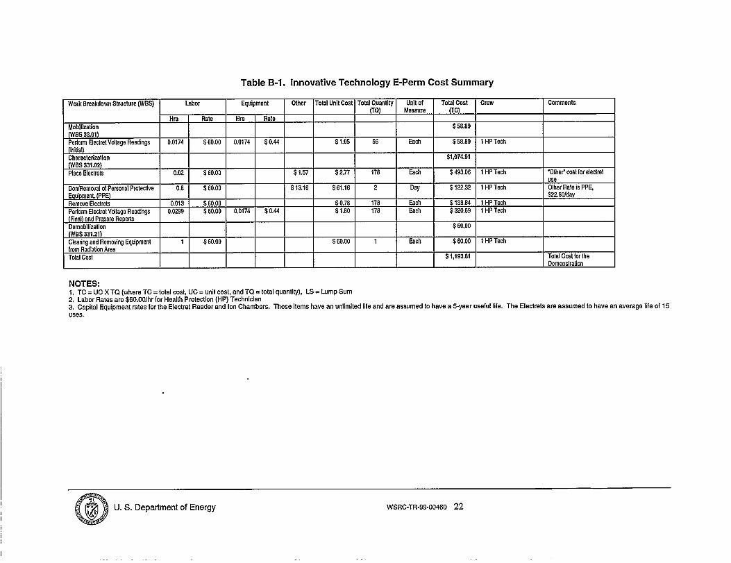
Table B-1. Innovative Technology E-Perm Cost Summary
Other I Total Unit Cost I Totsl QuantityWork Breakdown Structure (WBS) labor Equipment
Hrs Rate Hrs Rate
Mobilization(WBS 33.01)~donr Electrel Voltage Readings 0.0174 $60.00 0.0174 $0.44
Characterization(WBS 331.02)Place Eleclrels 0.02 $60.00
DordRemoval of Personal Protective 0.8 $60.00Equipment, (PPE)Remove Electrels 0.013 $60.00Perform Electret Vollage Readings 0,0299 $60.00 0.0174 $0.44(Final) and Prepare ReportsDemobilization(WBS 331.21)Cleating and Removing Equipmenl 1 $60.00from Radiation AreaTotal Cost
I I
$60.00 1
Unit of Total Coat Crew CommentsMeasure fTc)
$58.89
Each $58,89 1 HP Tech
$1,074.91
Each $493.06 1 HP Tech “Other” coat for eleclret
NOTES:1. TC = UC X TQ (where TC = total cost, UC = unit cost, and TQ = total quantity), LS = Lump Sum2. Labor Rates are $60.00/hr for Health Protection (HP) Technician3. Capital Equipment rates for the Electret Reader and Ion Chambers. These items have an unlimited life and are aaaumed to have a 5-year useful life. The Electrets are assumed to have an average fife of 15uses.
@i j ‘ U.S. Department of Energy WSRC-TR-99-O0460 22
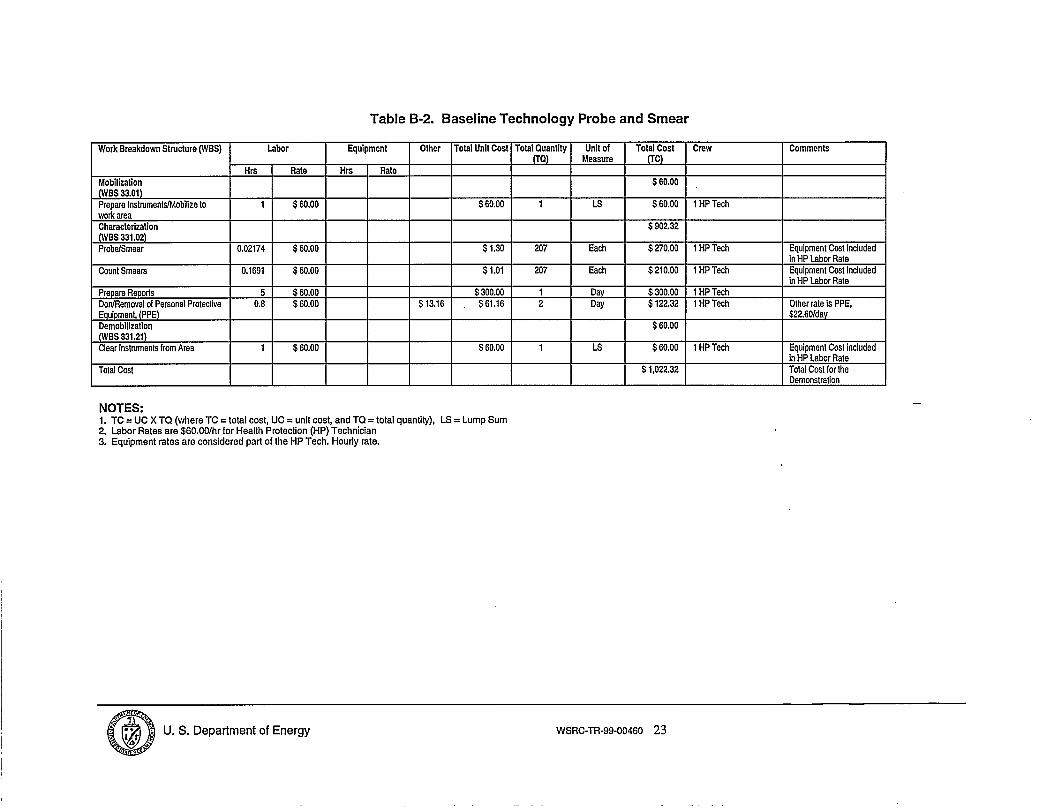
Table B-2. Baseline Technology Probe and Smear
Work Breakdown Structure (WBS) Labor Equipment
\Hrs Rate Hrs Rale
Mobilization(WBS 33.01)Prepare lnstrumenta/Mobifize to 1 $60.00work areaCharacterization(WBS 331.02)Probe/Smear 0.02174 $60.00
Count Smears 0.1691 $60.00
Prepare Reporta 5 $60.00DotiRemoval of Personal Protective 0.6 $60.00Equipment, (PPE)DemobilizationfWBS 331.21)Clear Inslmmenk from Area 1 $60.00
Total Cost
Other Total Unit Cost Tofal Quantity Unit of(TQ) Measure
I I I
I I I$60.00 1 LS
s300.00 1 Day$13.16 $61.16 2 Day
I I I
$60.00 1 LS
NOTES:1. TC = UC X TQ (where TC = total cost, UC = unit cost, and TQ = total quantity), LS = Lump Sum2. Labor Rates are $60.00/hr for Health Protection (HP) Technician3. Equipment rates are considered part of the HP Tech. Hourfy rate.
Total Cost(TC)
$60.00
$60.00
$902.32
$270.00
$210.00
$300.00$122.32
$60,00
$60.00
$1,022.32
Crew
1 HP Tech
1 HP Tech
1 HP Tech
1 HP Tech1 HP Tech
1HP Tech
Comments1
I
3Equipment Cosl includedin HP Labor RateEquipment Cost includedin HP Labor Rate
@i~r “ U.S. Department of Energy WSRC-TR-99-O0460 23

APPENDIX Cd
Acronym/Abbreviation Description
CA
CCR
DOE-SR
EIC
FDD
LC
LLW
LSDDP
Pc
RBA
RCO
Sc
SRS
SRTC
TCR
USACE
WSRC
Contamination area
Component Cleaning Room
Department of Energy – Savannah River
Electret Ionization Chamber
Facilities Decommissioning Division
Large ionization chamber
low level waste
Large Scale Demonstration and Deployment Project
Personal Computer
Radiological Buffer Area
Radiological Control Operations
Small ionization chamber
Savannah River Site
Savannah River Technology Center
Tube Cleaning Room
U. S. Army Corps of Engineers
Westinghouse Savannah River Company
aL.. —
+
4
i ~f
U. S. Department of Energy WSRC-TR-99-O0460 24