e-port home single installation guide - mounting systems
TRANSCRIPT

E-Port Home SingleInstallation guide

2
Congratulations on the purchase of the E-Port Home Single. It will provide you with numerous advantages – a covered spot for your vehicle, more independence from your electricity support, and – last but not least – a stylish and innovative design piece at your doorstep. In order for you to be fully satisfied with your product, we encourage you to get better acquainted with all the details included in the present guide.
Contents
1. Introduction 31.1 Brief description 31.2 About the Guide 31.3 Warnings 41.4 Safety 4
2. Technical description 52.1 Basic system information 52.2 Constituent components 62.3 Technical data 7
3. Important assembly instructions 3.1 Usage conditions 83.2 Preparation ahead of assembly 83.3 Aids and required tools 83.4 Assembly descriptions 8
4. Feet placement planning 9
5. Installation of transverse beams 105.1 Fixing the supports 105.2 Fixing the supports to the feet 11
6. Installation of the superstructure 126.1 Fixing the squares 126.2 Fixing the cross beams to the squares 126.3 Fixing the transverse lamellae 12
7. Fixing the trapezoidal sheet 137.1 Fixing the shield plate 14
8. Fixing the roof gutter 168.1 Downpipe 17
9. Planning the module area 18 for a transverse installation 19
10. Fixing the profile rails 19 for a transverse installation
11. Transverse installation of modules 2111.1 Fixing the Clickstones 2111.2 Fixing the modules from the outside 2311.3 Fixing the modules from the inside 2511.4 Fixing further rows 25

3E-Port Home Single
1. Introduction
1.1 Brief description
E-Port Home Double is a sturdy Double parking spot for a vehicle, allowing for an installation of up to 10 solar modules on its roof. The delivered items include the base frame of steel profiles and all other minor installation components to install the modules on the trapezoidal sheet root. The delivery also includes roof shield plates and a drainage system.
1.2 About the Guide
InstructionsThese instructions describe the installation of the E-Port Home system and fixing the PV modules on the roof. The guide also contains system-specific information on the planning of the work, safety indications and a list of the components to be installed.
Please read both this installation manual and the above mentioned documents carefully prior to any installation, maintenance or disassembly work. You will be provided with all information for safe and complete installation, maintenance and disassembly. However, if you have any questions after having read these documents, please contact Mounting Systems GmbH.
User groupThese installation instructions are intended for the following persons (user group):
• Skilled personnel• Instructed personnel
Skilled personnellSkilled personnel are persons who, on the basis of their professional training, are able to execute installation, maintenance and disassembly work properly.
Instructed personnelInstructed personnel are persons who have been instructed and taught appropriately regarding the assigned tasks and the possible risks in the event of improper conduct. An instructed person must have received instructions regarding the required safety devices, precautions, relevant regulations, accident prevention regulations as well as operating conditions and must have demonstrated their competence. The implemented work must be inspected and accepted by skilled personnel.
Guidance notesThe following guidance notes enhance the orientation when handling this installation manual:
Pictograms:
This symbol indicates important information and useful tips.
This Symbol indicates ways and means to make the installation process easier
i

4 Installation guide
1.3 Warnings
The following warnings are used in these Installation Instructions to indicate safety-related information. They include:
• Warning symbols (pictograms)• Signal words that identify the hazard level• Information about the type and source of the hazard• Information about the potential consequences if the hazard is disregarded • Measures for the prevention of hazards and the prevention of injuries or damage to property
The signal words of the warnings respectively indicate one of the following hazard levels:
1.4 Safety
All universally valid safety instructions for products of Mounting Systems GmbH are listed in the document “Installation manual for PV mounting systems – general part”. Please read this document carefully and observe the instructions given therein: Do not use the product in a manner other than intended, comply with the obligations of the owner and observe all general and specific safety instructions.
In addition, please observe the specific safety instructions given in this installation manual for all installation work. The specific safety instructions are positioned in each case directly with the respective installation step.
Indicates a potentially mortal danger, disregard for which may result in death or serious injury.
Indicates a potentially dangerous situation that may result in serious injury or damage to property.
Indicates a potentially dangerous situation that may result in injuries or damage to property if ignored.
Indicates potential danger that can result in damage to the property.
WARNING
CAUTION
ATTENTION
DANGER

5E-Port Home Single
2. Technical description 2.1 Basic system information
Below you will find the most important components of the system:
Picture 2.1-1 E-Port Home Single
Components of the E-Port Home Single:
a Supportb Squarec Trapezoidal sheetd Roof gutter
a
b
c
d
Picture 2.1-2 component weight
29kg1,5g
30kg
4kg
16kg
1kg
2kg
19kg
5.5kg

6 Installation guide
2.2 Constituent components
Check the delivery for completeness. Components of the vertical pipe in the drainage system (17-37) and the module installation kit (38) are not shown.
Foot = 4x
Cross brace = 2x
Transverse beam = 2x
Edge flashing short (400mm) = 5x Edge flashing long (1950mm) = 8x
Rear support = 2x
Sheet piece = 4x Sheet piece = 4x
Diagonal bracket left = 2x, right = 2x
Front support = 2x
Flashing holder = 3x Calotte = 76x
Square = 8x
Trapezoidal steel sheet = 4x
Unpacking and assembly require the participation of many people. The sheet metal components may bend out of shape.
CAUTION
1
84
11
15
2
9
5
12
16
3
10
7
14
14
6
13
13
Cross brace = 2x

7E-Port Home Single
2.3 Technical data
Part no. Count Designation
1 4 Foot
2 2 Rear support 80x80x3-2670mm
3 2 Front support 80x80x3-2230mm
4 2 Transverse beam 80x80x3-4345mm
5 4 Sheet piece
6 4 Sheet piece
7 2 Short cross brace
8 2 Long cross brace
9 8 Square
10 4 Transverse beam 80x80x3-4345mm
11 2 Diagonal bracket left
11 2 Diagonal bracket right
12 4 Trapezoidal steel sheet
13 1 Edge flashing short
14 2 Edge flashing long
15 3 Edge flashing long
16 76 Calotte – length 35_50mm
17 1 Roof gutter 120mm; 2m
18 1 Roof gutter 120mm; 2,4m
Part no. Count Designation
19 6 Gutter hook
20 2 Downpipe bend fi Ø90
21 1 Downpipe fi Ø90; 3m
22 1 Gutter bottom, left
23 1 Gutter bottom, right
24 1 Gutter connector
25 1 Drainage support 120/90
26 2 Downpipe clamp
27 1 Downpipe outlet
28 56 ISO 4017 - M16 x 120 (Bolt)
29 144 DIN 125 - A 17 (Washer)
30 72 ISO 4032 - M16 (Hex nut)
31 16 ISO 4017 - M16 x 110 ( Bolt)
32 30 M5,5x0,8 x 19 (Sheet metal screw )
33 76 M5,5x0,8 x 50 (Sheet metal screw )
34 16 Anchor bolt FAZ II 16/160
35 4 Cap
36 160 Screw cap – synthetic material,M16
37 40 ISO 4014 – M16x110
38 1 Module installation kit 720-1747 (frame height 33-45)
Set includes: • support structure for photovoltaic modules
• trapezoidal sheet for the entire structure (ca. 1,1m x 6,0m)
Foundation: Anchored in the ground
Easy installation not requiring special tools
Modules: Place for up to 10 modules (1.0m x 1.7m)
• for a module capacity of 300 Wp
• total power 3 kWp
Options: • Roof side shielding
• Drainage
Colour: Black, matt (RAL 9005)
Condition: No shadow
8 Installation guide
3. Important assembly instructions
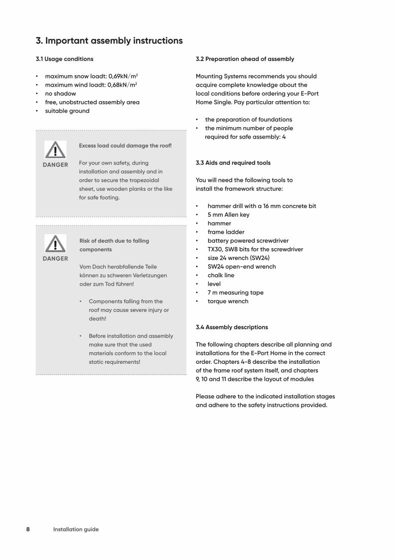
3.1 Usage conditions
• maximum snow loadt: 0,69kN/m2
• maximum wind loadt: 0,68kN/m2
• no shadow• free, unobstructed assembly area• suitable ground
3.2 Preparation ahead of assembly
Mounting Systems recommends you should acquire complete knowledge about the local conditions before ordering your E-Port Home Single. Pay particular attention to:
• the preparation of foundations• the minimum number of people required for safe assembly: 4
3.3 Aids and required tools
You will need the following tools to install the framework structure:
• hammer drill with a 16 mm concrete bit• 5 mm Allen key• hammer• frame ladder• battery powered screwdriver• TX30, SW8 bits for the screwdriver• size 24 wrench (SW24)• SW24 open-end wrench• chalk line• level• 7 m measuring tape• torque wrench
3.4 Assembly descriptions
The following chapters describe all planning and installations for the E-Port Home in the correct order. Chapters 4-8 describe the installation of the frame roof system itself, and chapters 9, 10 and 11 describe the layout of modules
Please adhere to the indicated installation stages and adhere to the safety instructions provided.
Excess load could damage the roof!
For your own safety, during installation and assembly and in order to secure the trapezoidal sheet, use wooden planks or the like for safe footing.
Risk of death due to fallingcomponents
Vom Dach herabfallende Teilekönnen zu schweren Verletzungenoder zum Tod führen!
• Components falling from the roof may cause severe injury or death!
• Before installation and assembly make sure that the used materials conform to the local static requirements!
DANGER
DANGER

9E-Port Home Single
4. Feet placement planning
A-A ( 1 : 50 )
A A
A
B
1
E
D
C
2 3 4 5
formatFormat
sheetBlatt
casc
drawing numberZeichnungsnummerMounting Systems GmbH
Mittenwalder Str. 9a15834 Rangsdorf
nameName
dateDatum
nameName
dateDatum
modificationÄnderung
status Zust.
acceptable toleranceZul. Abw.
surfaceOberfl.
drawer
scaleMaßstab
checked
Engineering
single carport
Einzelcarport
821-0100
weightGewicht
04.02.2020
______
index Index
field of applicationVerwendungsbereich
mountingsystems
a 27.03.20 dajaPos.13,30,33,34,40-42,46
bhinzugefügt. Blatt 04-06Pos.48,49 06.07.20 daja
4240 3000
3000
4240
42456100
2995
2363
5194
2820
4060
Measure the placement of the feet (1) and fix them in the measured positions. For this purpose, use the anchors installed in the prepared foundation.
Picture 4.-1
Make sure that the feet are aligned(1) properly so that the supports (2)and (3) can be installed in them asneeded.
ATTENTION
Installation steps:Fix the four feet in the concrete foundation; each foot is installed using four bolts (34).
Torque settings:• Bolt anchorr M16 - 110Nm

55Nm
10 Installation guide
5. Installation of transverse beams The supports (2) and (3) and transverse beams (4) must be laid out as needed beside both feet (1).
5.1 Fixing the supports
Installation steps:
• Fix the support (2) to the beam (4) using two sheet pieces (5), four M16x120 bolts, eight washers and four nuts.
• Fix the support (3) to the beam (4) by two sheet pieces (6), four M16x120 bolts, four washers and two nuts.
• The transverse beam (7) between the support (2) and beam (4) is fixed by two M16x110 bolts, four washers and two nuts.
• The transverse beam (8) between the support (3) and beam (4) is fixed by two M16x110 bolts, four washers and two nuts, just like in the step above.
Picture 5.-1
Picture 5.1-1
Picture 5.1-2
Picture 5.1-3
4
4
4
4
2
2 3
5
6
3
5
7
2
6
5
Picture 5.1-1.1
Picture 5.1-1.2
55Nm
35Nm

11E-Port Home Single
5.2 Fixing the supports to the feet
Installation steps:
• The screwed construction is to be placed in the feet (1).
• Then fix the supports to the feet (1) using four M16x100 bolts, eight washers and four nuts.
• Repeat item 5 and fox the other side component in the other two feet (1).
Picture 5.2-1
Risk of death due to fallingcomponents
Components falling from the roof maycause severe injury or death!
• Components that fall when the structure is erected may cause grave injury and component damage!
DANGER
1
31
45Nm

40Nm
40Nm
40Nm
12 Installation guide
6. Installation of the superstructure
6.1 Fixing the squares
Each square (9) is fixed to the beam (4) at the designated spot using two M16x110 bolts, four washers and two nuts
6.3 Fixing the transverse lamellae
Installation steps:• Fix the transverse lamellae (11 each on left
and right side) to the outer cross beams (10)• • Fixing of the beam (4) requires a M16x110 bolt,
two washers and a M16 nut.
• Fixing of the cross beam (10) requires a M16x110 bolt, two washers and a M16 nut.
• Next place the plates in the support openings and cover the nuts with caps.
6.2 Fixing the cross beams to the squares
The cross beams (10) are fixed to the ready squares (7) using one M16x110 bolt, two washers and one nut per square (9).
Picture 6.2-1
Picture 6.3-1Picture 6.1-1
9
9
11
4
10
4
10
Picture6.1-2
6.1-2 Position of bracket (9) see picture
10
10
10
10
13E-Port Home Single
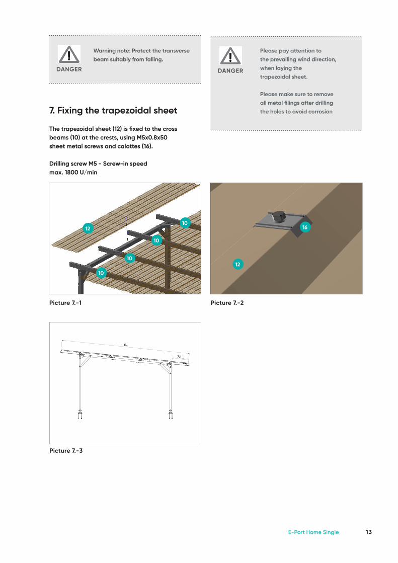
7. Fixing the trapezoidal sheet The trapezoidal sheet (12) is fixed to the cross beams (10) at the crests, using M5x0.8x50 sheet metal screws and calottes (16).
Drilling screw M5 - Screw-in speed max. 1800 U/min
Picture 7.-1 Picture 7.-2
12
1612
Warning note: Protect the transverse beam suitably from falling.
DANGER
Please pay attention tothe prevailing wind direction,when laying thetrapezoidal sheet.
Please make sure to remove all metal filings after drilling the holes to avoid corrosion
DANGER
A-A ( 1 : 25 )
A
B
1
E
D
C
2 3 4 5
Toleranz-klasse
c
m
von 0,5bis3
über 3bis 6
über 6bis 30
über 30bis 120
über 120bis 400
über 400bis 1000
über 1000bis 2000
über 2000bis 4000
Abw. für Längenmaße (Außen-,Innen-,Absatz-,Abstands-,Durchmesser-,Bearbeitungsmaße)
0,1 0,1 0,2 0,3 0,5 0,8 1,2 2,0
0,2 0,3 0,5 0,8 1,2 2,0 3,0 4,0
Abweichungen für Winkelmaße für den kürzeren Schenkels des betreffenden Winkels
bis 10
1°
1°,3´
über 10bis 50
0°,30´
1°
über 50bis 120
0°,20´
0°,30´
über 120bis 400
0°,10´
0°,15´
über 400
0°,5´
0°,10´
formatFormat
sheetBlatt
d.janczewski
drawing numberZeichnungsnummerMounting Systems GmbH
Mittenwalder Str. 9a15834 Rangsdorf
general tolerance / Allgemeintoleranz
nameNamedateDatum
DIN EN 12020-2: 2017-06
800,798 kg/m
acceptable tolerance / Zul. Abw.
material, semifinished productWerkstoff, Halbzeug
Einzelcarport
821-01001/1
19.03.2021
mountingsystems A3
drawerZeichner
controlkontrolliert engineering
Description
Beschreibung
Uncontrolled when printed Copyright © 2020 Mounting Systems GmbH Rangsdorf
Cross section values / Querschnitt Werte
Ix (cm^4) Iy (cm^4)
A(cm^2)
Y
X
total perimeter (mm)Gesamtumfang
weight / Gewicht
78 cm
6m
Picture 7.-3
14 Installation guide
Picture 7.1-1
Picture 7.1-2
Picture 7.1-3
14 1413
14
14
14
13
13
14 13 14
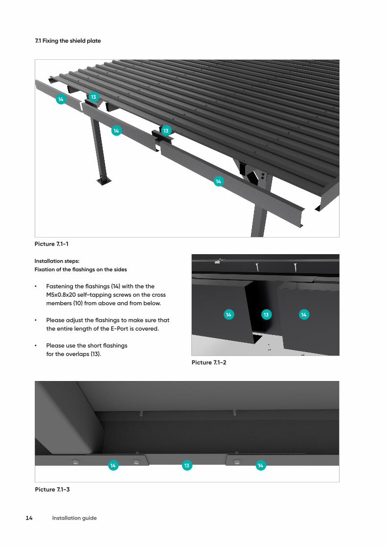
7.1 Fixing the shield plate
Installation steps:Fixation of the flashings on the sides
• Fastening the flashings (14) with the the M5x0.8x20 self-tapping screws on the cross members (10) from above and from below.
• Please adjust the flashings to make sure that the entire length of the E-Port is covered.
• Please use the short flashings for the overlaps (13).

15E-Port Home Single
Picture 7.1-6 Picture 7.1-7
14 14
Picture 7.1-4 Picture 7.1-5
14
12
15
Please use two self-tapping screws each to fix the overlap at the corner from above and from below.
Installation steps:Fixation of the flashings at the front and backside
• Fasten the flashing (14) with the flashing holder (15) to the trapezoidal sheet (12), using a self-tapping screw from above and below through the flashing.

16 Installation guide
Picture 8.1-1
Installation of the gutter connectors:
• Both gutter components must be slid together, then insulate the opening above and below the connection.
• Correct the installation by extending the middle piece above the rear end of the roof gutter and then above the front edge of the gutter.
• Manually compress the middle piece so that it touches with the roof gutter.
• Then bend the latches to so that the clamps close.
8. Fixing the roof gutter
Installation steps:
• In the roof gutter (17) cut out an opening where the downpipe is to be fixed (21)
• Install the roof gutter to the sheet metal crests using the roof hooks/ clamps and sheet metal screws.
• Pick even distances between the roof hooks.
Fixing the hooks to the gutter:
• Space six hooks along the entire roof length (distance between hooks - ca. 84 cm).
• The roof hooks are attached to the trapezoidal sheet from below and with the help of two screws / rivets per hook from above, please make sure that there is a fall of 2% in the direction of the downpipe.
Picture 8.-2
Picture 8.-1
Picture 8.-3
17
17
25
20
19
17 24 18
21
Picture 8.-4
Y
X

17E-Port Home Single
Picture 8.1-2
Picture 8.1-3
21
3
26
27
X [cm] 80 70 60
Connector length[cm]
ca. 70 ca. 60 ca. 50
8.1 DownpipeThe three metre downpipe is divided into thepipe proper and the connector.
• The downpipe hopper is fixed to the roof gutter using the prepared opening.
• Fix the downpipe to the support (3) with clamps.
• The connector length is determined by the roof overhang.
• Measure the value of X and use the table below to calculate the length of the middle component.
• Cut away pieces of the drain pipe will serve as connectors.
• Fix the downpipe clamp ca. 10 cm below the lower square and above the upper square.

18 Installation guide
For a transverse installation, use short rail pieces (GS 1/15 CS) of 100 mm. Determine the spacing using the outer dimensions of the installed modules and the spa-cing of the sheet metal crests. Adhere to the positioning of the clamping points as described by the manufactu-rer. The spacing of the rails is determined as follows:
1 Module field height: vertical module count x (module width + 19 mm) + 41 mm
2 Module field width: horizontal module count x module length (+ possible sum total of gaps)
3 Module length
4 Module width
5 Vertical spacing between two rail pieces: Module width – 82 mm (free space between rails, tolerance +/ - 1 mm)
6 Free space between modules = 17-19 mm
7 Spacing between rail components along module column: ca. 1/ 2 x module length, depending on spacing of sheet crests (the rail pieces are fixed to the crests).
9. Planning the module area for a transverse installation
Mortal danger due to damage to roof
Excess loads may cause grave damage to the roof!
• Before installation and fixing, make sure that the building, and in particular the roof covering, will conform to the increased static equirements due to installation of the PV system.
DANGER
Risk of death due to falling compo-nents
Components falling from the roof may cause severe injury or death!
• Before installation and assembly make sure that the used mate-rials conform to the local static requirements!
DANGER
Picture 9.-1
1
6
4
7
5
3
2
19E-Port Home Single
10. Fixing the profile rails for a transverse installation
For a cross installation, install 100 mm rail components (GS 1/15 CS). EPDM insulation bands are already in place, they do not to be embedded again. The rails are fixed directly to the sheet metal crests using two thin sheet screws.
Mortal hazard in case of fall from the roof!
A fall from the roof may cause gra-ve injury or death!
• Always wear the required PPE!• Protect yourself from falling!• If the wind is too strong, cease
all works.
DANGER
Risk of death due to falling com-ponents
Components falling from the roof may cause severe injury or death!
• Before commencing the installa-tion, secure the perimeter so that nobody is injured due to falling components!
• Make sure that nothing at all can fall from the roof.
• Always wear the statutory requi-red PPE!
• Do not remain in the hazard zone!
• If the wind is too strong, cease all works.
• When installation is completed, check whether the frame and modules are properly installed.
DANGER
20 Installation guide
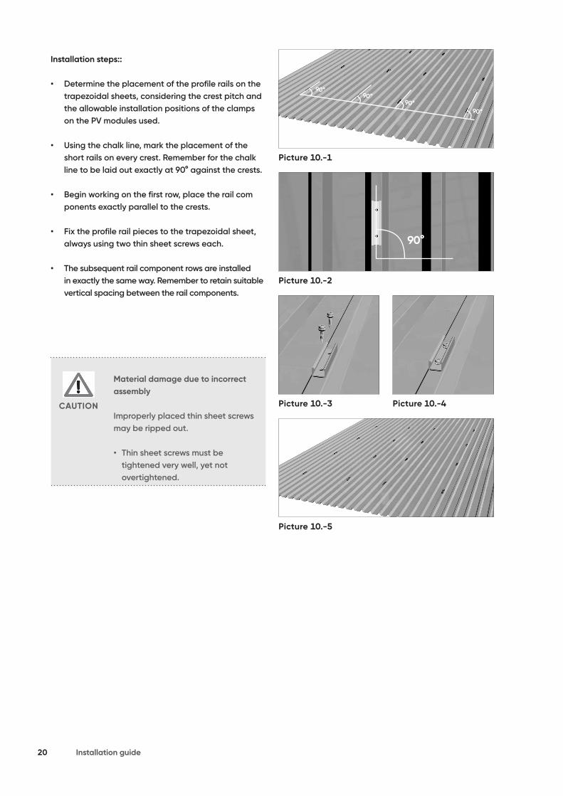
Installation steps::
• Determine the placement of the profile rails on the trapezoidal sheets, considering the crest pitch and the allowable installation positions of the clamps on the PV modules used.
• Using the chalk line, mark the placement of the short rails on every crest. Remember for the chalk line to be laid out exactly at 90° against the crests.
• Begin working on the first row, place the rail com ponents exactly parallel to the crests.
• Fix the profile rail pieces to the trapezoidal sheet, always using two thin sheet screws each.
• The subsequent rail component rows are installed in exactly the same way. Remember to retain suitable vertical spacing between the rail components.
Material damage due to incorrect assembly
Improperly placed thin sheet screws may be ripped out.
• Thin sheet screws must be tightened very well, yet not overtightened.
CAUTION
Picture 10.-1
Picture 10.-2
Picture 10.-3
Picture 10.-5
Picture 10.-4

21E-Port Home Single
11. Transverse installation of modules
The modules are installed one after another on the profile rails. Mounting Systems GmbH recommends that modules be installed row after row, bottom to top. The modules are fixed using clamps and end clamps. The end clamps are foreseen for holding a Double module, with ordinary clamps usually placed between two modules.
11.1 Fixing the Clickstones
The installation of modules uses Clickstones. The Clickstone is a special support used to fix the profile rails. Installation requires just an Allen key (5 mm). Clickstones are slid into the profile rail channels from the top.
Installation steps:
• Slide the Clickstone into the rail channel from the top.
• Press the Clickstone down. A click will be heard as it is fixed in place.
• Tighten the Allen key with a torque of 8 Nm.
iNote!The Clickstone shape corresponds exactly to the channel profile. The Clickstones are constructed so that it is not easy to move them sideways so they don’t slide away. In order to shift the Clickstone, press the screw down lightly and slide the component in the rail channel, pressing on it gently.
1
3 4
2
Picture 11.1-1

22 Installation guide
iNote!The noses on the internal sides of the Clickstones are constructed so that it is impossible for them to become dislocated when the screw is tightened. Accordingly, the screw may be loosened slightly so that it protrudes above the nose level; only then remove the Clickstone from the base rail by compressing it slightly and raising it.
Damage to material due to incorrect installation
Incorrectly installed Clickstones may be ripped out. The modules may fall and become damaged.
• Install all Clickstone connections as foreseen by the manual.
CAUTION
Material damage due to damage to Clickstones.
When using significantly deformed Clickstones, proper and safe installation of modules cannot be guaranteed. Modules are at a risk of falling and damage.
• Only use Clickstones, whose noses are parallel to each other, and which click audibly when locking in place.• Replace deformed Clickstones before assembly.
CAUTION
1
3 4
2
Picture 11.1-2

23E-Port Home Single
11.2 Fixing the modules from the outside
Edge modules in a PV arrangement (and for a transverse installation – the top and lowest module row) are fixed from the outside using two edge clamps at the top and two at the bottom.
Installation steps:
• Slide the Clickstone for the end clamp after centering it in the rail channel.• Put the module on top and level it.• Slide the module end clamp all the way to the frame.• Tighten the screw (torque: 8 Nm), the module is clamped.
Proper placement of the end clamp: Centrally, between the thin sheet metal screws!
Picture 11.2-1
Picture 11.2-2
Picture 11.2-4
Picture 11.2-3

24 Installation guide
Picture 11.2-5
Picture 11.2-6
Picture 11.2-8
Picture 11.2-7
Material damage due to incorrect installation
Modules install the wrong way may fall and become damaged.
• Make sure the Clickstones are fixed properly.• Slide the module all the way to the end clamp.• When tightening screws, adhere to the indicated torque values.• After installation make sure that the module really is fixed well.
CAUTION
Material damage due to incorrect installation
Overloaded thin sheet screws may be ripped out.
• Note the correct placement of the module end clamps. The Clickstone must be found between both thin sheet screws in the rail component.
CAUTION

25E-Port Home Single
11.3 Fixing the modules from the inside
Always fix two module clamps between modules.
Installation steps:
• Embed the Clickstone in the profile rail channel.
• Slide the module clamp all the way to the frame of the module already installed.
• Slide the second module to the module clamp; lay out properly.
• Tighten the screw (torque: 8 Nm),so the module is properly fixed.
Proper placement of the end clamp: Centrally, between the thin sheet metal screws!
Material damage due to incorrect installation
Modules install the wrong way may fall and become damaged.
• Make sure the Clickstones are fixed properly.• Slide the module all the way to the end clamp.• When tightening screws, adhere to the indicated torque values.• After installation make sure that the module really is fixed well.
CAUTION
Material damage due to incorrect installation
Overloaded thin sheet screws may be ripped out.
• Note the correct placement of the module end clamps. The Clickstone must be found between both thin sheet screws in the rail component.
CAUTION
Picture 11.3-1
Picture 11.3-2
Picture 11.3-5
Picture 11.3-7
Picture 11.3-4
Picture 11.3-3
Picture 11.3-6

26 Installation guide
11.4 Fixing further rows
Installation steps:
• For the further columns, the modules must be slid from the side to the modules of the first outer row. For optical reasons, if necessary, one may retain a specific spacing from the lower module.
• Fix the modules from the first column using clamps and end clamps (see 10.2 and 10.3).
iNote!Use e. g. the module clamp as a distance indicator. In this way, one can achieve the same vertical and horizontal distances between modules.
Picture 11.4-1
Picture 11.4-2
Picture11.4-3 Module field E-Port Home Single

27E-Port Home Single

Mounting Systems GmbHMittenwalder Straße 9aD-15834 Rangsdorf
Tel: +49 33708/529-100Fax: +49 33708/529-199
Technische Änderungen vorbehalten 2021 © Mounting Systems GmbH
Mounting Systems GmbHRolshover Straße 524D-51105 Köln
Tel. +49 221-29277-600Fax: +49 221-29277-629
E-P
ort
-Ho
me
-Sin
gle
-V0
1-M
A-E
N-1
1032
1