e- rider - ace-mfg.comace-mfg.com/wp-content/uploads/2018/02/2018_ezriderpartscatalog.pdf · for...
TRANSCRIPT
Heavy Duty ClutchesFlywheels & Accessories
ACE MANUFACTURING AND PARTS CO.300 Ramsey StreetSullivan, MO 63080
For Immediate Assistance
1-800-325-613824/7 TECHNICAL SUPPORT
E-Z RIDER®
February 2018
Made in the U.S.A.


ACE-MFG.COM • [email protected] • [email protected]
TABLE OF CONTENTSE-Z Rider Manual Adjust Features ................................................................................4
E-Z Rider Self-Adjust Features......................................................................................5
Top Selling Products ......................................................................................................6
Determining Proper Clutch ............................................................................................7
Metric Push Type Clutch 310mm and 350mm.......................................................................................................8
Medium Duty Clutch 14” Stamped Steel .........................................................................................................8 14” x 1.75” Cast for Flat Flywheel..................................................................................9 14” x 2” Cast for Flat Flywheel.....................................................................................10 14” x 1.75” Cast for Pot Flywheel ................................................................................11 14” x 2” Cast for Pot Flywheel .....................................................................................11
Heavy Duty Clutch 15.5” x 2”, 8 Spring – Manual Adjust ...........................................................................12 15.5” x 2”, 10 Spring – Manual Adjust .........................................................................13 15.5” x 2”, 7 Spring – Manual Adjust and Self-Adjust ..................................................14 15.5” x 2”, 9 Spring – Manual Adjust and Self-Adjust ..................................................15
Flywheels Caterpillar ....................................................................................................................16 Cummins ............................................................................................................... 17-18 Detroit ..........................................................................................................................19 Ford-Sterling ................................................................................................................19 Mack ............................................................................................................................20 Navistar-International ..................................................................................................21 Volvo/Mercedes ...........................................................................................................22
Clutch Accessories ......................................................................................................23
Clutch Installation Kits .................................................................................................24
15.5” E-Z Rider Assembly – Exploded View ................................................................25
Manual Adjust Clutch Installation.................................................................................26
Self-Adjust Clutch Installation ......................................................................................30
Maintenance Tips ........................................................................................................35
Troubleshooting – Clutch Operation ............................................................................36
Checklist – Before Removing Clutch ...........................................................................37
Engine Horsepower & Torque Ratings ........................................................................38
Contacts ......................................................................................................................47
TAB
LE O
F CO
NT
EN
TS

For Immediate Assistance • 1-800-325-6138 • 24/7 TECHNICAL SUPPORT4
E-Z
RID
ER
MA
NU
AL
AD
JUS
T F
EA
TU
RE
SE-Z Rider Manual Adjust Clutch
15.5” E-Z Rider Features
Patented cryogentically treated springs virtually eliminate disc spring failures
Superior Lead Free Ceramic Friction
Bushings are pressed and then crimped into sleeve promoting longer bushing life
Sealed and permanently lubed release bearing is standard on all E-Z Rider assemblies
Patented self locking adjuster with no lock to remove or depress - just turn to adjust
Note: The features above are not included on standard pedal units.

ACE-MFG.COM • [email protected]
E-Z
RID
ER
SE
LF-AD
JUS
T FE
AT
UR
ES
Serviceability• No complicated reset procedure• Resets with Manual Adjuster• Same procedure as manual adjust clutch
Contamination Prevention Technology• Self-contained components in adjuster
maintain optimal adjusting function• Patent Pending Actively Expanding Seal
(A.E.S.) creates an industry first anti-contamination enclosure
• Specialized lubrication ensures optimal adjustments throughout the life of the clutch
Installation• No need to retrain technicians• Same installation procedure as manual adjust clutch
Will NOT over adjust• Not susceptible to outside forces (i.e. backing into dock or hitting potholes
during disengagement)
Robust Adjuster Design• Positively engaged ratchet system • 4-lug drive gear has the capability to deliver over 50 ft*lbs of torque to the
adjusting ring• Self-locking worm gear ensures positive adjustment
How it worksDuring clutch disengagement, if release bearing travel is 1/2” or less, no adjustment is necessary and the built-in lost release bearing position.
When the clutch wears, release bearing travel increases beyond lost motion window and advances worm gear. The worm gear then turns the adjusting ring to compensate for wear, repositioning the release bearing.
On clutch engagement, one way ratchet advances and restores the ideal lost motion window.
Self-Adjust Clutch
Design Features
For Immediate Assistance • 1-800-325-6138 • 24/7 TECHNICAL SUPPORT6
TOP
10
SE
LLIN
G
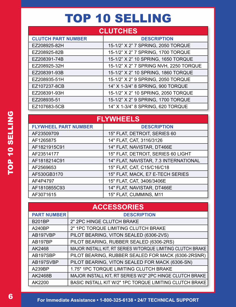
CLUTCHESCLUTCH PART NUMBER DESCRIPTIONEZ208925-82H 15-1/2” X 2” 7 SPRING, 2050 TORQUEEZ208925-82B 15-1/2” X 2” 7 SPRING, 1700 TORQUEEZ208391-74B 15-1/2” X 2” 10 SPRING, 1650 TORQUEEZ208925-32H 15-1/2” X 2” 7 SPRING NVH, 2250 TORQUEEZ208391-93B 15-1/2” X 2” 10 SPRING, 1860 TORQUEEZ208935-51H 15-1/2” X 2” 9 SPRING, 2050 TORQUEEZ107237-8CB 14” X 1-3/4” 8 SPRING, 900 TORQUEEZ208391-93H 15-1/2” X 2” 10 SPRING, 2050 TORQUEEZ208935-51 15-1/2” X 2” 9 SPRING, 1700 TORQUEEZ107683-5CB 14” X 1-3/4” 8 SPRING, 620 TORQUE
FLYWHEELSFLYWHEEL PART NUMBER DESCRIPTIONAF23509709 15" FLAT, DETROIT, SERIES 60AF1265875 14" FLAT, CAT, 3116/3126AF1821915C91 14" FLAT, NAVISTAR, DT466EAF23514177 15" FLAT, DETROIT, SERIES 60 LIGHTAF1818214C91 14" FLAT, NAVISTAR, 7.3 INTERNATIONALAF2569653 15" FLAT, CAT, C15/C16/C18AF530GB3170 15" FLAT, MACK, E7 E-TECH SERIESAF4P4797 15" FLAT, CAT, 3406/3406EAF1810855C93 14" FLAT, NAVISTAR, DT466EAF3071615 15" FLAT, CUMMINS, M11
ACCESSORIESPART NUMBER DESCRIPTIONB201BP 2" 2PC HINGE CLUTCH BRAKEA240BP 2" 1PC TORQUE LIMITING CLUTCH BRAKEAB197VBP PILOT BEARING, VITON SEALED (6306-2VS)AB197BP PILOT BEARING, RUBBER SEALED (6306-2RS)AK2468 MAJOR INSTALL KIT, RT SERIES W/TORQUE LIMITING CLUTCH BRAKEAB197SBP PILOT BEARING, RUBBER SEALED FOR MACK (6306-2RSNR)AB197SVBP PILOT BEARING, VITON SEALED FOR MACK (6306-SN)A239BP 1.75" 1PC TORQUE LIMITING CLUTCH BRAKEAK2468B MAJOR INSTALL KIT, RT SERIES W/2" 2PC HINGE CLUTCH BRAKEAK2200 BASIC INSTALL KIT W/2" 1PC TORQUE LIMITING CLUTCH BRAKE
TOP 10 SELLING

ACE-MFG.COM • [email protected]
Determining The Proper Clutch For Your Vehicle
1. Determine the size of the clutch. (14” or 15.5”)
2. Determine flywheel bore by measuring the center of flywheel opening (Dimension ‘A’ in the illustration). All 14” clutches use 8 spring disc assemblies and can be used only with 7” flywheel bore size regardless of flat or pot style flywheels. For 15.5” clutches, approximate flywheel bore sizes are 7, 8.5” or 10”.
A. If flywheel bore is 7”, ONLY use an 8 spring disc. B. If flywheel bore is 8.5”, use a 10 spring disc. C. If flywheel bore is 10”, use a 7 spring (NVH), or a 9 spring (*Mack). D. If you have a 10” flywheel bore, DO NOT USE ORGANIC FACING. The facing
I.D. will extend into the flywheel bore opening, not having full facing contact.
3. Determine engine torque at current settings. (See Page 38-Torque Chart)
4. Identify linkage type - Mechanical or Hydraulic. For mechanical linkage you may use either a manual adjust clutch or a self-adjust clutch. Manual adjust clutches are not recommended for hydraulic release systems.
DE
TE
RM
INE
PR
OP
ER
CLU
TCH
1.75” or 2” 14” or 15.5”

For Immediate Assistance • 1-800-325-6138 • 24/7 TECHNICAL SUPPORT8
Metric Clutches
Medium Duty14” Stamped Steel Clutch
8 Spring, 7” Flywheel Bore
DESCRIPTION TORQUE DISC STYLE PART NUMBER
310MM 400 1-1/2” - 6 Springs 4 Pad AM107606-1
DESCRIPTION TORQUE DISC STYLE PART NUMBER
350MM 500 1-1/2” - 8 Springs 4 Pad AM107621-1
350MM 500 1-3/4” - 8 Springs 4 Pad AM107620-2
ME
TR
IC P
US
H T
YP
E/1
4” S
TAM
PE
D S
TE
EL
TORQUE DISC STYLE PEDAL ADJ PART NUMBER
860 1-3/4” - 8 Springs 3 Pad STD EZ AM107237-10
860 2” - 8 Springs 3 Pad STD EZ AM107342-12
Dual Disc

ACE-MFG.COM • [email protected]
Heavy Duty Clutch for Medium Duty Truck
14” x 1-3/4” For 14” Flat Flywheel8 Spring, 7” Flywheel Bore
Dual Disc
Single Disc
14” CA
ST
CO
VE
R
TORQUE DISC STYLE PEDAL ADJ PART NUMBER
900 Ceramic 8 Spring 3 Pad Co - Ft EZ EZ EZ107237-8CB
TORQUE DISC STYLE PEDAL ADJ PART NUMBER
950 Ceramic 8 Spring 4 Pad Co - Ft EZ EZ EZ107237-4CB
TORQUE DISC STYLE PEDAL ADJ PART NUMBER
620 Ceramic 8 Spring 3 Pad Co - Ft EZ EZ EZ107683-5CB
TORQUE DISC STYLE PEDAL ADJ PART NUMBER
680 Ceramic 8 Spring 4 Pad Co - Ft EZ EZ EZ107683-4CB
680 Ceramic 8 Spring 4 Pad Co - Ft EZ EZ EZ107915-1CB*
*Mercedes Only

For Immediate Assistance • 1-800-325-6138 • 24/7 TECHNICAL SUPPORT10
14”
CA
ST
CO
VE
RHeavy Duty Clutch
for Medium Duty Truck 14” x 2” For 14” Flat Flywheel
8 Spring, 7” Flywheel Bore
TORQUE DISC STYLE PEDAL ADJ PART NUMBER
900 Ceramic 8 Spring 3 Pad Co - Ft EZ EZ EZ107686-2CB
TORQUE DISC STYLE PEDAL ADJ PART NUMBER
950 Ceramic 8 Spring 4 Pad Co - Ft EZ EZ EZ107686-4CB
AB197VBP6306
AB197SVBP6306•S
(Mack Application)
Dual Disc
ACE-MFG.COM • [email protected]
14” CA
ST
CO
VE
R – P
OT
ST
YLE
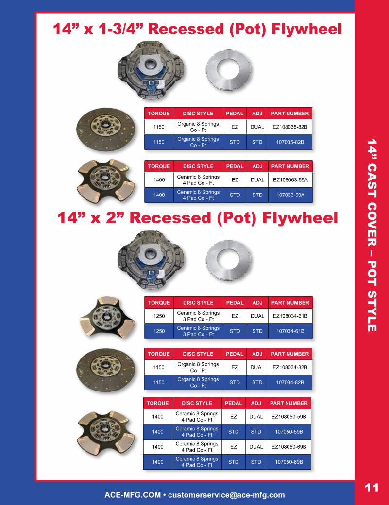
14” x 2” Recessed (Pot) Flywheel
TORQUE DISC STYLE PEDAL ADJ PART NUMBER
1250 Ceramic 8 Springs 3 Pad Co - Ft EZ DUAL EZ108034-61B
1250 Ceramic 8 Springs 3 Pad Co - Ft STD STD 107034-61B
TORQUE DISC STYLE PEDAL ADJ PART NUMBER
1150 Organic 8 Springs Co - Ft EZ DUAL EZ108034-82B
1150 Organic 8 Springs Co - Ft STD STD 107034-82B
TORQUE DISC STYLE PEDAL ADJ PART NUMBER
1400 Ceramic 8 Springs 4 Pad Co - Ft EZ DUAL EZ108050-59B
1400 Ceramic 8 Springs 4 Pad Co - Ft STD STD 107050-59B
1400 Ceramic 8 Springs 4 Pad Co - Ft EZ DUAL EZ108050-69B
1400 Ceramic 8 Springs 4 Pad Co - Ft STD STD 107050-69B
14” x 1-3/4” Recessed (Pot) Flywheel
TORQUE DISC STYLE PEDAL ADJ PART NUMBER
1150 Organic 8 Springs Co - Ft EZ DUAL EZ108035-82B
1150 Organic 8 Springs Co - Ft STD STD 107035-82B
TORQUE DISC STYLE PEDAL ADJ PART NUMBER
1400 Ceramic 8 Springs 4 Pad Co - Ft EZ DUAL EZ108063-59A
1400 Ceramic 8 Springs 4 Pad Co - Ft STD STD 107063-59A
For Immediate Assistance • 1-800-325-6138 • 24/7 TECHNICAL SUPPORT12
15-1
/2”
CLU
TCH
– 8
SP
RIN
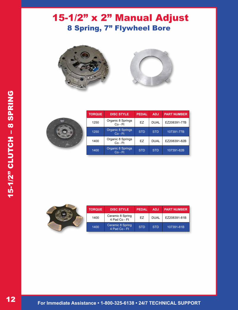
G 15-1/2” x 2” Manual Adjust
8 Spring, 7” Flywheel Bore
TORQUE DISC STYLE PEDAL ADJ PART NUMBER
1400 Ceramic 8 Spring 4 Pad Co - Ft EZ DUAL EZ208391-81B
1400 Ceramic 8 Spring 4 Pad Co - Ft STD STD 107391-81B
TORQUE DISC STYLE PEDAL ADJ PART NUMBER
1250 Organic 8 Springs Co - Ft EZ DUAL EZ208391-77B
1250 Organic 8 Springs Co - Ft STD STD 107391-77B
1400 Organic 8 Springs Co - Ft EZ DUAL EZ208391-82B
1400 Organic 8 Springs Co - Ft STD STD 107391-82B
ACE-MFG.COM • [email protected]
15-1/2” CLU
TCH
– 10 SP
RIN
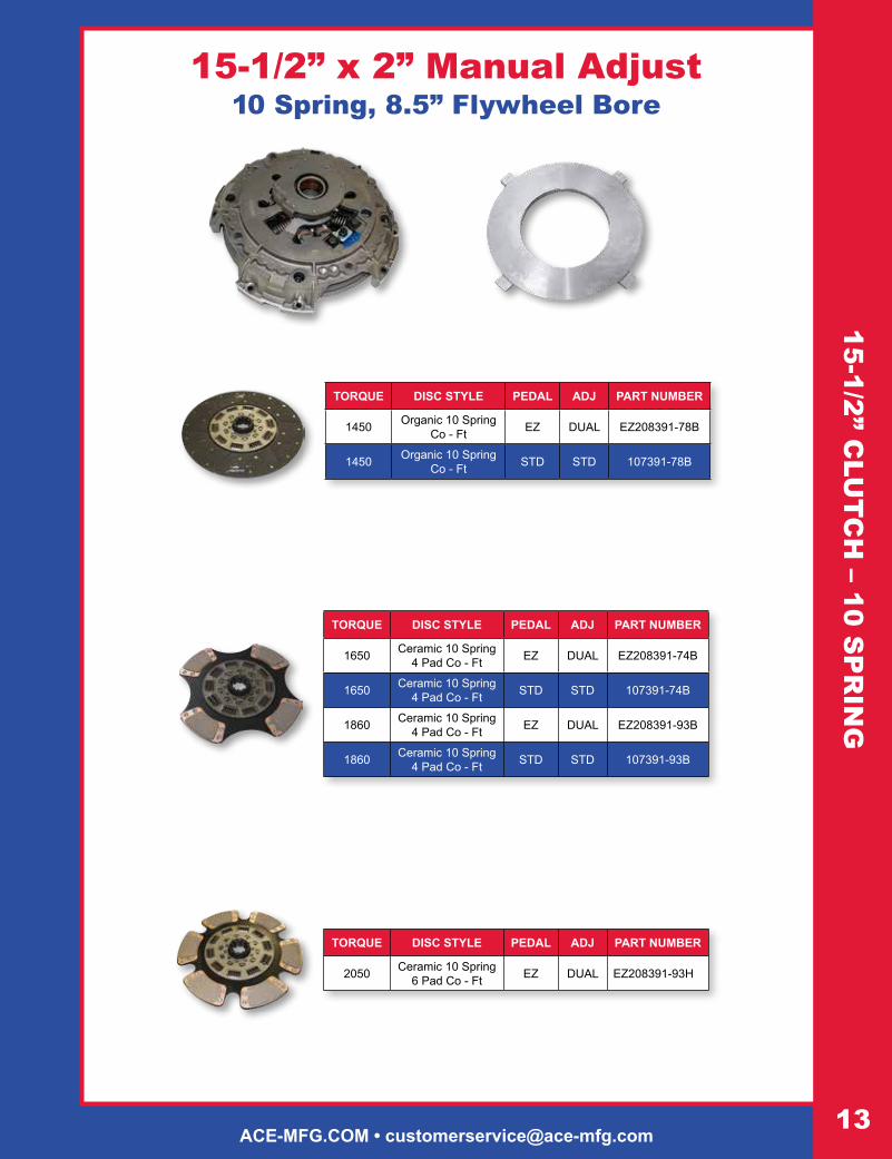
G15-1/2” x 2” Manual Adjust
10 Spring, 8.5” Flywheel Bore
TORQUE DISC STYLE PEDAL ADJ PART NUMBER
2050 Ceramic 10 Spring 6 Pad Co - Ft EZ DUAL EZ208391-93H
TORQUE DISC STYLE PEDAL ADJ PART NUMBER
1450 Organic 10 Spring Co - Ft EZ DUAL EZ208391-78B
1450 Organic 10 Spring Co - Ft STD STD 107391-78B
TORQUE DISC STYLE PEDAL ADJ PART NUMBER
1650 Ceramic 10 Spring 4 Pad Co - Ft EZ DUAL EZ208391-74B
1650 Ceramic 10 Spring 4 Pad Co - Ft STD STD 107391-74B
1860 Ceramic 10 Spring 4 Pad Co - Ft EZ DUAL EZ208391-93B
1860 Ceramic 10 Spring 4 Pad Co - Ft STD STD 107391-93B

For Immediate Assistance • 1-800-325-6138 • 24/7 TECHNICAL SUPPORT14
15-1/2” x 2” Manual Adjust7 Spring, 10” Flywheel Bore
15-1/2” x 2” Self-Adjust 7 Spring 10” Flywheel Bore
TORQUE DISC STYLE PEDAL ADJ PART NUMBER
2050 Ceramic 7 Spring 6 Pad Co - Ft EZ DUAL EZ208925-82H
2050 Ceramic 7 Spring NVH 6 Pad Co - Ft EZ DUAL EZ208925-25
2250 Ceramic 7 Spring NVH 6 Pad Co - Ft EZ DUAL EZ208925-32H
TORQUE DISC STYLE PEDAL ADJ PART NUMBER
1700 Ceramic 7 Spring 4 Pad Co - Ft EZ DUAL EZ208925-82B
1700 Ceramic 7 Spring 4 Pad Co - Ft STD STD 107925-82B
TORQUE DISC STYLE PEDAL ADJ PART NUMBER
1700 Ceramic 7 Spring 4 Pad Co - Ft EZ DUAL EZ209925-82B
TORQUE DISC STYLE PEDAL ADJ PART NUMBER
1760 Ceramic 7 Spring 6 Pad Co - Ft EZ DUAL EZ209925-85
2050 Ceramic 7 Spring NVH 6 Pad Co - Ft EZ DUAL EZ209925-82H
15-1
/2”
CLU
TCH
– 7
SPR
ING
NVH Disc Shown
NVH Disc Shown

ACE-MFG.COM • [email protected]
15-1/2” CLU
TCH
– 9 SP
RIN
G15-1/2” x 2” Manual Adjust
9 Spring, 10” Flywheel Bore
15-1/2” x 2” Self-Adjust 9 Spring 10” Flywheel Bore
TORQUE DISC STYLE PEDAL ADJ PART NUMBER
1700 Ceramic 9 Spring 4 Pad Co - Ft EZ DUAL EZ209935-51
TORQUE DISC STYLE PEDAL ADJ PART NUMBER
1700 Ceramic 9 Spring 4 Pad Co - Ft EZ DUAL EZ208935-51*
1700 Ceramic 9 Spring 4 Pad Co - Ft STD STD 107935-51*
TORQUE DISC STYLE PEDAL ADJ PART NUMBER
2050 Ceramic 9 Spring 6 Pad Co - Ft EZ DUAL EZ208935-51H*
*Fits Mack and Various Volvo Models. Check Manufacturer’s Specifications
TORQUE DISC STYLE PEDAL ADJ PART NUMBER
2050 Ceramic 9 Spring 6 Pad Co - Ft EZ DUAL EZ209935-51H
*Fits Mack and Various Volvo Models. Check Manufacturer’s Specifications

For Immediate Assistance • 1-800-325-6138 • 24/7 TECHNICAL SUPPORT16
FLY
WH
EE
LS-C
AT
ER
PIL
LAR
FlywheelsACE CATALOG # AF4P4797 DESCRIPTION APPLICATION
15” FLAT FLYWHEEL10” BORE
12 MOUNTING BOLT HOLESUSE 7 SPRING CLUTCH
BEARING # AB197BP (6306)113 TEETH
RING GEAR # 4N2514
CAT3406/3406E
ACE CATALOG # AF9Y9311 DESCRIPTION APPLICATION
14” FLAT FLYWHEEL7” BORE
10 MOUNTING BOLT HOLESUSE WITH 8 SPRING CLUTCH
BEARING # AB199BP (6305) OR BEARING # AB190BP (6206)
134 TEETHRING GEAR # 9L8113
OR RING GEAR # 968113
CAT3208
ACE CATALOG # AF1265875 DESCRIPTION APPLICATION
14” FLAT FLYWHEEL7” BORE
8 MOUNTING BOLT HOLES1 DOWEL PINHOLE
BEARING # AB190BP (6206-2RS)134 TEETH
RING GEAR # 7W5095
CAT3116/3126
ACE CATALOG # AF4P8515 DESCRIPTION APPLICATION
15” FLAT FLYWHEEL10” BORE
8 MOUNTING BOLT HOLESUSE 7 SPRING CLUTCH
BEARING # AB197BP (6306)113 TEETH
RING GEAR # 4N2514
CAT3176, C10, C12
ACE CATALOG #AF2569653 DESCRIPTION APPLICATION
15” FLAT FLYWHEEL10” BORE
12 MOUNTING BOLTSUSE 7 SPRING CLUTCH
BEARING # AB197BP (6306)113 TEETH
RING GEAR # 4N2514
CATC15, C16, C18
ACE-MFG.COM • [email protected]
FLYW
HE
ELS
-CU
MM
INS
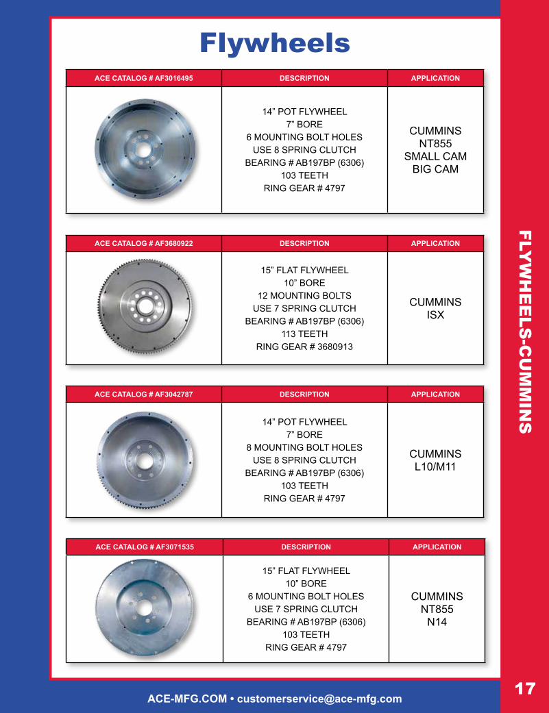
FlywheelsACE CATALOG # AF3016495 DESCRIPTION APPLICATION
14” POT FLYWHEEL7” BORE
6 MOUNTING BOLT HOLESUSE 8 SPRING CLUTCH
BEARING # AB197BP (6306)103 TEETH
RING GEAR # 4797
CUMMINSNT855
SMALL CAMBIG CAM
ACE CATALOG # AF3042787 DESCRIPTION APPLICATION
14” POT FLYWHEEL7” BORE
8 MOUNTING BOLT HOLESUSE 8 SPRING CLUTCH
BEARING # AB197BP (6306)103 TEETH
RING GEAR # 4797
CUMMINSL10/M11
ACE CATALOG # AF3680922 DESCRIPTION APPLICATION
15” FLAT FLYWHEEL 10” BORE
12 MOUNTING BOLTSUSE 7 SPRING CLUTCH
BEARING # AB197BP (6306)113 TEETH
RING GEAR # 3680913
CUMMINSISX
ACE CATALOG # AF3071535 DESCRIPTION APPLICATION
15” FLAT FLYWHEEL10” BORE
6 MOUNTING BOLT HOLESUSE 7 SPRING CLUTCH
BEARING # AB197BP (6306)103 TEETH
RING GEAR # 4797
CUMMINSNT855
N14

For Immediate Assistance • 1-800-325-6138 • 24/7 TECHNICAL SUPPORT18
FLY
WH
EE
LS-C
UM
MIN
SFlywheels
ACE CATALOG # AF3071615 DESCRIPTION APPLICATION
15” FLAT FLYWHEEL10” BORE
8 MOUNTING BOLT HOLESUSE 7 SPRING CLUTCH
BEARING # AB197BP (6306)103 TEETH
RING GEAR # 4797
CUMMINSM11
ACE CATALOG # AF3921263 DESCRIPTION APPLICATION
14” FLAT FLYWHEEL7” BORE
8 MOUNTING BOLT HOLESUSE 8 SPRING CLUTCH
BEARING # AB190BP (6206)173 TEETH.540 THICK
RING GEAR # 3903309
CUMMINS5.9-B
ACE CATALOG # AF3922645 DESCRIPTION APPLICATION
14” FLAT FLYWHEEL 7” BORE
8 MOUNTING BOLT HOLESUSE 8 SPRING CLUTCH
BEARING AB190BP (6206)138 TEETH.875 THICK
RING GEAR # 3902127
CUMMINS8.3 C Series

ACE-MFG.COM • [email protected]
FLYWHEELS-DETROIT/FORD
Flywheels
Ford-Sterling
ACE CATALOG # AF23509709 DESCRIPTION APPLICATION
15” FLAT FLYWHEEL10” BORE
12 MOUNTING BOLT HOLESUSE 7 SPRING CLUTCH
BEARING # AB197BP (6306)118 TEETH
RING GEAR # 5166664
DETROITSERIES 60
ACE CATALOG # AF2354177 DESCRIPTION APPLICATION
15” FLAT FLYWHEEL10” BORE
12 MOUNTING BOLT HOLESUSE 7 SPRING CLUTCH
BEARING # AB197BP (6306)118 TEETH
RING GEAR # 5166664
DETROIT 60 LIGHTWEIGHT
ACE CATALOG # AF8922126 DESCRIPTION APPLICATION
14” FLAT FLYWHEEL7” BORE
8 MOUNTING BOLT HOLESUSE 8 SPRING CLUTCH
BEARING # AB195BP (6205)138 TEETH
RING GEAR # 5116302
DETROIT8.2
ACE CATALOG # AFE7HZ6375A DESCRIPTION APPLICATION
14” FLAT FLYWHEEL7” BORE
8 MOUNTING BOLT HOLESUSE 8 SPRING CLUTCH
BEARING # AB190BP (6206)138 TEETH
RING GEAR # E6HZ6384A
FORD6.6 & 7.8

For Immediate Assistance • 1-800-325-6138 • 24/7 TECHNICAL SUPPORT20
FLY
WH
EE
LS-M
AC
KFlywheels
ACE CATALOG # AF530GB3142 DESCRIPTION APPLICATION
15” FLAT FLYWHEEL10” BORE
6 METRIC BOLT HOLESUSE 9 SPRING CLUTCH
BEARING # AB197SBP (6306-2RSNR)118 TEETH
RING GEAR # 673GB222
MACK675 & 676
ACE CATALOG # AF530GB3145B DESCRIPTION APPLICATION
15” FLAT FLYWHEEL10” BORE
6 METRIC BOLT HOLESUSE 9 SPRING CLUTCH
BEARING # AB197SBP (6306-2RSNR)118 TEETH
RING GEAR # 673GB222
MACKE7
ACE CATALOG # AF530GB3170 DESCRIPTION APPLICATION
15” FLAT FLYWHEEL10” BORE
6 METRIC BOLT HOLESUSE 9 SPRING CLUTCH
BEARING # AB197SBP (6306-2RSNR)117 TEETH (2 NOTCHED)
RING GEAR # 673GB35
MACKE7
E-TECH SERIES

ACE-MFG.COM • [email protected]
FLYW
HE
ELS
-NA
VIS
TAR
FlywheelsACE CATALOG # AF1809144C91 DESCRIPTION APPLICATION
14” FLAT FYWHEEL7” BORE
9 MOUNTING BOLT HOLESUSE 8 SPRING CLUTCH
BEARING # AB195BP (6205)137 TEETH
RING GEAR # 1800777C1
NAVISTAR7.3
INTERNATIONAL
6.9INTERNATIONAL
ACE CATALOG # AF1810855C93 DESCRIPTION APPLICATION
14” FLAT FYWHEEL7” BORE
8 MOUNTING BOLT HOLESUSE 8 SPRING CLUTCH
BEARING # AB195BP (6205)138 TEETH
RING GEAR # 1815440C1
NAVISTARDT466
ACE CATALOG # AF1818214C91 DESCRIPTION APPLICATION
14” FLAT FLYWHEEL7” BORE
10 MOUNTING BOLT HOLESUSE 8 SPRING CLUTCH
BEARING # AB190BP (6206)OR BEARING # AB199BP (6305)
137 TEETH RING GEAR # 1800777C1
NAVISTAR7.3
INTERNATIONAL
ACE CATALOG # AF1821915C91 DESCRIPTION APPLICATION
14” FLAT FLYWHEEL7” BORE
12 MOUNTING BOLT HOLESUSE 8 SPRING CLUTCH
BEARING # AB190BP (6206)OR BEARING # AB199BP (6305)
138 TEETH RING GEAR # 1815440C1
NAVISTARDT466E

For Immediate Assistance • 1-800-325-6138 • 24/7 TECHNICAL SUPPORT22
FLY
WH
EE
LS-V
OLV
O/M
ER
CE
DE
SFlywheels
ACE CATALOG # AF20790714 DESCRIPTION APPLICATION
15” FLAT FLYWHEEL10” BORE
12 MOUNTING BOLTS USE 7 SPRING CLUTCH
BEARING # AB197VBP (6306)153 TEETH
RING GEAR # 20711957
VOLVOVED 11
ACE CATALOG # AF20730056 DESCRIPTION APPLICATION
15” FLAT FLYWHEEL10” BORE
14 MOUNTING BOLTS USE 7 SPRING CLUTCH
BEARING # AB197BP (6306)153 TEETH
RING GEAR # 20711957
VOLVOVED 12
ACE CATALOG # AF4600300305 DESCRIPTION APPLICATION
15” FLAT FLYWHEEL 10” BORE
10 MOUNTING BOLTSUSE 7 SPRING CLUTCH
BEARING # AB190BP (6206)160 TEETH
MERCEDESMBE 4000
Mercedes
Volvo

ACE-MFG.COM • [email protected]
CLU
TCH
AC
CESSO
RIES
A119BPDRIVE PIN
CSF105C137RELEASE FORK
A230EZBPEZ ADJUSTER
A239BP/A240BPTORQUE LIMITING CLUTCH
BRAKE
B175BP/B201BP/B201-450BP/B201-500BP
QUICK CHANGEHINGE BRAKE
AB195BP/AB197BP/AB197VBP
PILOT BEARING
AB195SBP/AB197SBP/AB197SVBP
PILOT BEARING
AT-HT150/AT-HT175/ATHT175A/ AT-HT175X1/AT-HT200
ALIGNMENT TOOL
IPS1659, IPS2822INPUT SHAFT 2”
10 SPLINE W/BUSHINGA148BP/A153BP
FIBER DISC
IG100FLYWHEEL GUAGE
CSB12815BPBUSHING - BELL HOUSING
Clutch AccessoriesPart Number Reference Description
A119BP 274C-6 Drive Pin 14” Flywheel (6 per bag)
A148BP 2” Brake Spacer (6 per bag)
A153BP 1.75” Brake Spacer (6 per bag)
A239BP 127740 1.75” 1pc Torque Limiting Clutch Brake
A240BP 127760 2” 1pc Torque Limiting Clutch Brake
B175BP 1.75” 2pc Hinge Clutch Brake
B201BP 2” 2pc Hinge Clutch Brake
B201-450BP 2” Oversized 2pc Hinge Clutch Brake .450 thick
B201-500BP 2” Oversized 2pc Hinge Clutch Brake .500 thick
A230EZBP 125300 EZ Adjuster
AB195BP 6205-2RS Pilot Bearing (rubber sealed)
AB195SBP 6205-2RSNR Pilot Bearing (rubber sealed for Mack)
AB197BP 6206-2RS Pilot Bearing (rubber sealed)
AB197SBP 6306-2RSNR Pilot Bearing (rubber sealed for Mack)
AB197VBP 6306-2VS Pilot Bearing (Viton sealed)
AB197SVBP 6306-SN Pilot Bearing (Viton sealed for Mack)
CSB12815BP 12815 Shaft Bushing (4 per bag)
CSF105C-137 105C-137 Release Fork
IG100 Flywheel Gauge
ATK200 Clutch Installation Tool Kit
IPS1659 S-1659 Input Shaft
IPS2822 S-2822 Input Shaft
Alignment
AT-HT150 1.50 X 10 SPLINE .980 pilot
AT-HT175 1.75 X 10 SPLINE 1.180 pilot
AT-HT175A 1.75 X 10 SPLINE .980 pilot
AT-HT175X1 1.75 X 10 SPLINE 1.0 pilot
AT-HT200 2.00 X 10 SPLINE 1.180 pilot
Installation Kits
AK2468 RT SERIES Major install kit w/torque limiting clutch brake
AK2468B RT SERIES Major install kit w/2 pc. clutch brake
AK3600 FR SERIES Major install kit w/torque limting clutch brake
AK3600B FR SERIES Major install kit w/2 pc. clutch brake
AK3762 RT SEVERE DUTY Major install kit w/torque limiting clutch brake
AK3762B RT SEVERE DUTY Major install kit w/2 pc. clutch brake
AK2175 1.75” Minor install kit w/torque limiting clutch brake
AK2200 2” Minor install kit w/torque limiting clutch brake
AK2201 2” Minor install kit w/2 pc. clutch brake

For Immediate Assistance • 1-800-325-6138 • 24/7 TECHNICAL SUPPORT24
CLU
TCH
KIT
S
Part #AK2175 Includes: (1) CSF105C137 Fork (1) A239 1.75” Torque Limiting Clutch Brake (4) CSB12815 Bushings
Part #AK2200 Includes: (1) CSF105C137 Fork (1) A240 2” Torque Limiting Clutch Brake (4) CSB12815 Bushings
Part # AK2201 Includes: (1) CSF105C137 Fork (1) B201 2” Hinged Clutch Brake (4) CSB12815 Bushings
Basic Clutch Installation Kit
Complete Clutch Installation KitFor FR Series Transmissions
Part #AK3600 Includes: 2” Torque Limiting Clutch Brake (A240) and Roller Bearing
Part #AK3600B Includes: 2” Hinged Clutch Brake (B201) and Roller Bearing
For RT Series Transmissions
Part #AK2468 Includes: 2” Torque Limiting Clutch Brake (A240) and Ball Bearing
Part #AK2468B Includes: 2” Hinged Clutch Brake (B201) and Ball Bearing
Part #AK3762 Severe Duty Includes: 2” Torque Limiting Clutch Brake (A240) and Roller Bearing
Part #AK3762B Severe Duty Includes: 2” Hinged Clutch Brake (B201) and Roller Bearing
• Clutch Housing Gasket• Front Bearing Cover
Gasket• Inner Retaining Ring• Outer Retaining Ring• Front Bearing Cover• 2” Torque Limiting
Clutch Brake
• Shift Lever Housing Gasket
• Bearing w/Snap Ring• Pilot Bearing• Cross Shaft Bushings• Standard Release Yoke• 2” - 10 Spline Input Shaft
This clutch installation kit includes the following:
ACE-MFG.COM • [email protected]
15.5” E-Z
RID
ER
® AS
SE
MB
LY
ACE MANUFACTURING & PARTS CO., INC. 300 Ramsey - Sullivan, MO 63080 Phone: (573) 468-4181 • Fax: (573) 468-5584
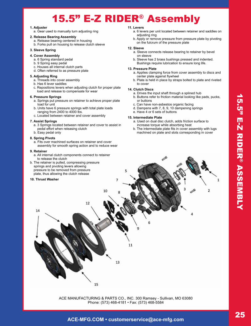
1. Adjuster a. Gear used to manually turn adjusting ring
2. Release Bearing Assembly a. Release bearing centered in housing b. Forks pull on housing to release clutch sleeve
3. Sleeve Spring4. Cover Assembly
a. 6 Spring standard pedal b. 9 Spring easy pedal c. Houses all internal clutch parts d. Often referred to as pressure plate
5. Adjusting Ring a. Threads into cover assembly b. Has 6 lever saddles c. Repositions levers when adjusting clutch for proper plate
load and release to compensate for wear
6. Pressure Springs a. Springs put pressure on retainer to achieve proper plate
load for unit b. Units have 6 pressure springs with total plate loads
ranging from 2400 to 4000 lbs. c. Located between retainer and cover assembly
7. Assist Springs a. 3 Springs located between retainer and cover to assist in
pedal effort when releasing clutch b. Easy pedal only
8. Spring Pivots a. Fits over machined surfaces on retainer and cover
assembly for smooth spring action and to reduce wear
9. Retainer a. All internal clutch components connect to retainer
to release the clutchb. The retainer is pulled, compressing pressure
springs and pivoting levers allowing pressure to be removed from pressure plate, thus allowing the clutch release
10. Thrust Washer
15.5” E-Z RIDER® Assembly11. Levers
a. 6 levers per unit located between retainer and saddles on adjusting ring
b. Apply or remove pressure from pressure plate by pivoting on the fulcrum of the pressure plate
12. Sleeve a. Sleeve connects release bearing to retainer by bevel
on sleeve b. Sleeve has 2 brass bushings pressed and indented.
Bushings require lubrication to ensure long life.
13. Pressure Plate a. Applies clamping force from cover assembly to discs and
center plate against flywheel b. Plate is held in place by straps bolted to plate and riveted
to cover
14. Clutch Discs a. Drives the input shaft through a splined hub b. Buttons refer to friction material looking like pads, pucks,
or buttons c. Can have non-asbestos organic facing d. Dampens with 7, 8, 9, 10 dampening springs e. Have 4 or 6 sets of buttons
15. Intermediate Plate a. Used on dual disc clutch, adds friction surface to
increase torque while absorbing heat b. The intermediate plate fits in cover assembly with lugs
machined on plate and slots corresponding in cover
For Immediate Assistance • 1-800-325-6138 • 24/7 TECHNICAL SUPPORT26
MA
NU
AL
AD
JUS
T I
NS
TALL
AT
ION
GU
IDE
Manual Adjust Clutch
Installation Guide
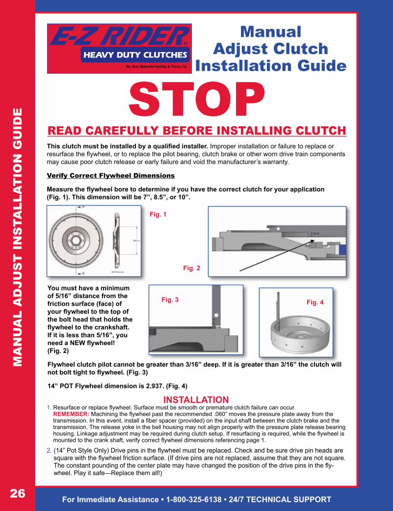
STOPREAD CAREFULLY BEFORE INSTALLING CLUTCHThis clutch must be installed by a qualified installer. Improper installation or failure to replace or resurface the flywheel, or to replace the pilot bearing, clutch brake or other worn drive train components may cause poor clutch release or early failure and void the manufacturer’s warranty.
Verify Correct Flywheel Dimensions
Measure the flywheel bore to determine if you have the correct clutch for your application (Fig. 1). This dimension will be 7”, 8.5”, or 10”.
You must have a minimum of 5/16” distance from the friction surface (face) of your flywheel to the top of the bolt head that holds the flywheel to the crankshaft. If it is less than 5/16”, you need a NEW flywheel! (Fig. 2)
Flywheel clutch pilot cannot be greater than 3/16” deep. If it is greater than 3/16” the clutch will not bolt tight to flywheel. (Fig. 3)
14” POT Flywheel dimension is 2.937. (Fig. 4)
INSTALLATION1. Resurface or replace flywheel. Surface must be smooth or premature clutch failure can occur.
REMEMBER: Machining the flywheel past the recommended .060” moves the pressure plate away from the transmission. In this event, install a fiber spacer (provided) on the input shaft between the clutch brake and the transmission. The release yoke in the bell housing may not align properly with the pressure plate release bearing housing. Linkage adjustment may be required during clutch setup. If resurfacing is required, while the flywheel is mounted to the crank shaft, verify correct flywheel dimensions referencing page 1.
2. (14” Pot Style Only) Drive pins in the flywheel must be replaced. Check and be sure drive pin heads are square with the flywheel friction surface. (If drive pins are not replaced, assume that they are not square. The constant pounding of the center plate may have changed the position of the drive pins in the fly-wheel. Play it safe—Replace them all!)
Fig. 1
Fig. 3
Fig. 2
Fig. 4

ACE-MFG.COM • [email protected]
MA
NU
AL A
DJU
ST
INS
TALLA
TIO
N G
UID
E3. (14” Pot Style Only) After the drive pins are installed and properly aligned, position the center plate onto the drive
pins and check the clearance with a feeler gauge. Clearance should be .006” to .010” and be measured from the same side of the drive pin at each location. The center plate should move up and down freely on the pins.
4. Inspect and dial-indicate the mating surface of engine flywheel housing and clutch bell housing for alignment. Check flywheel run out. CAUTION: If misalignment is greater than the recommended limits, this will cause poor clutch release, rapid wear on transmission input shaft and destruction of the clutch disc. Excessive flywheel run out may cause severe vibration in vehicle drive line. (Fig.5)
5. A new pilot bearing with a VITON® seal must be used. Before installing pilot bearing into flywheel, check freedom of movement on transmission input shaft.
6. Verify disc fits in flywheel bore (Fig. 1). Slide disc the length of the input shaft checking for twist and wear. Insert alignment shaft through bearing housing. Install rear disc (oriented correctly), center plate, and front disc (oriented correctly) on alignment shaft. Move clutch housing towards flywheel making sure cover fits into flywheel pilot.
7. Install the bolts that fasten the clutch housing on the flywheel. Tighten the bolts to the specified torque and the sequence specified by the manufacturer of the vehicle or transmission (7/16 x 14unc x 2-1/4 recommended 40-50 ft*lbs) (3/8 x 1 1/4 recommended 25-35 ft*lbs.) Bolts should be Grade 5 or greater.
8. Remove caging fork from under the release bearing. Remove alignment shaft. Verify bearing distance from cover is 1/2” - 5/8” (Fig. 6). NOTE: Any time the clutch is removed from the flywheel, the caging fork needs to be reinstalled.
9. Reconnect lube hose attachment (For Hydraulic Linkage Systems).
MEASURING ENGINE FLYWHEEL HOUSING AND FLYWHEELNOTE: Pilot Bearing must be replaced. Make sure aIl gauge contact surfaces are clean and dry.
CHECK THE FOLLOWING USING A DIAL INDICATOR:
Fig. 5
Flywheel Face RunoutSecure dial indicator base to flywheel housing face. Put gauge finger in contact with flywheel face near the outer edge. Rotate flywheel one revolution. Maximum runout is . 008” (.20 mm).
Pilot Bearing Bore RunoutSecure dial indicator base to flywheel housing face. Position gauge finger so that it contacts pilot bearing bore. Rotate flywheel one revolution. Maximum runout is .005” (.13 mm).
Flywheel Housing I.D. RunoutSecure dial indicator base to crankshaft. Put gauge finger against flywheel housing pilot 1.0. Rotate flywheel one revo-lution. Maximum runout is .008 (.20 mm).
Flywheel Housing Face RunoutSecure dial indicator base to flywheel near the outer edge. Put gauge finger in contact with face of flywheel housing. Rotate flywheel one revolution. Maximum runout is .008”(.20 mm).
Fig. 6

For Immediate Assistance • 1-800-325-6138 • 24/7 TECHNICAL SUPPORT28
10. Examine transmission input shaft and clutch release system components for wear and replace if necessary. (Fig. 7)
11. Install fiber spacer and replace clutch brake (fiber spacer not needed if over-sized clutch brake is used).
12 Be sure to properly lube the following components with NLGI grade 2 or 3 Lithium complex grease: Release Bearing, Yoke Fingers, Cross Shaft Bushings, and Linkage Pivot Points. Note: Applying enough grease to the release bearing until visible will extend the life of sleeve bushings and input shaft.
13. Using extreme caution, guide transmission through clutch cover, disc assemblies, and into pilot bearing rotating bell housing shaft so that release yoke fingers are clear of the pads on the release bearing assembly. (Warning: Transmission must not hang or be forced into the clutch. This can warp the clutch disc and prevent the clutch from releasing.) NOTE: Do not add lube to input shaft splines!
14. Start bell housing bolts and tighten progressively to the torque recommended by the vehicle manufacturer.15. Install clutch linkage. See “Clutch Set Up Procedure”.
CLUTCH SET UP PROCEDURENOTE: Clutches are adjusted at the factory to original equipment specifications and should require very little internal adjustment to achieve proper release and engagement. The clutch must not be adjusted to accommodate thin or worn flywheels, or worn linkage, yoke and/or cross shaft bushings, or to accommodate other drive train deficiencies. Adjust-ment for such purposes will either cause the clutch to not function properly or will cause early clutch failure and will be apparent on factory inspection of warranty claims, thereby voiding the manufacturer warranty.STEP #1 After transmission installation, check the clearance between the yoke tips and wear pads on bearing housing for 1/8” clearance. This determines pedal free play (Mechanical Linkage Only). (See Fig. 8)Adjust the clutch linkage to increase or decrease the yoke-to-bearing clearance. NEVER USE THE INTERNAL CLUTCH ADJUSTMENT FOR THIS PURPOSE.STEP #2 Check for proper clutch brake and bearing gap of 1/2” to 9/16”. If the gap is too small verify DIM B (Fig. 6 or Fig. 8). If DIM B is correct and a fiber spacer or oversized clutch brake was installed, remove the fiber spacer and/or replace over-sized clutch brake with standard thickness clutch brake. NOTE: If the gap is larger than 9/16” and DIM B is correct then one of the following conditions exists. Fiber spacer/over-sized clutch brake was not installed or you need to re-measure input shaft length as seen in Fig. 7. DO NOT ADJUST THE CLUTCH
MA
NU
AL
AD
JUS
T I
NS
TALL
AT
ION
GU
IDE
ACE-MFG.COM • [email protected]
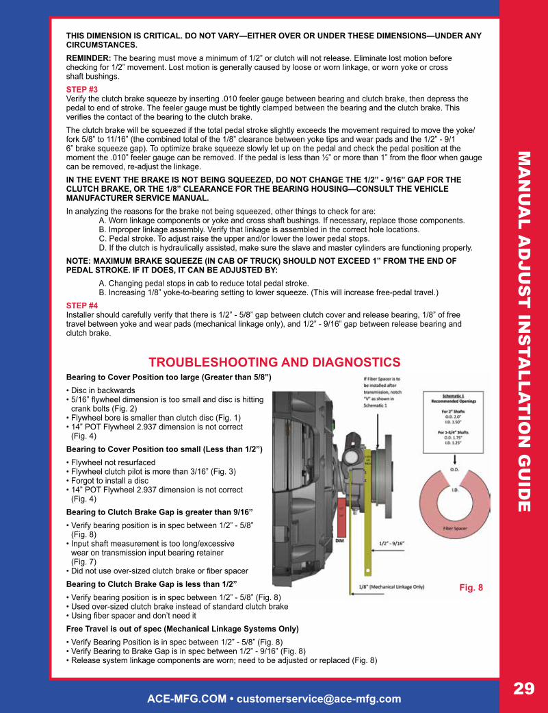
THIS DIMENSION IS CRITICAL. DO NOT VARY—EITHER OVER OR UNDER THESE DIMENSIONS—UNDER ANY CIRCUMSTANCES. REMINDER: The bearing must move a minimum of 1/2” or clutch will not release. Eliminate lost motion before checking for 1/2” movement. Lost motion is generally caused by loose or worn linkage, or worn yoke or cross shaft bushings.STEP #3 Verify the clutch brake squeeze by inserting .010 feeler gauge between bearing and clutch brake, then depress the pedal to end of stroke. The feeler gauge must be tightly clamped between the bearing and the clutch brake. This verifies the contact of the bearing to the clutch brake.The clutch brake will be squeezed if the total pedal stroke slightly exceeds the movement required to move the yoke/fork 5/8” to 11/16” (the combined total of the 1/8” clearance between yoke tips and wear pads and the 1/2” - 9/1 6” brake squeeze gap). To optimize brake squeeze slowly let up on the pedal and check the pedal position at the moment the .010” feeler gauge can be removed. If the pedal is less than ½” or more than 1” from the floor when gauge can be removed, re-adjust the linkage.IN THE EVENT THE BRAKE IS NOT BEING SQUEEZED, DO NOT CHANGE THE 1/2” - 9/16” GAP FOR THE CLUTCH BRAKE, OR THE 1/8” CLEARANCE FOR THE BEARING HOUSING—CONSULT THE VEHICLE MANUFACTURER SERVICE MANUAL.In analyzing the reasons for the brake not being squeezed, other things to check for are: A. Worn linkage components or yoke and cross shaft bushings. If necessary, replace those components. B. Improper linkage assembly. Verify that linkage is assembled in the correct hole locations. C. Pedal stroke. To adjust raise the upper and/or lower the lower pedal stops. D. If the clutch is hydraulically assisted, make sure the slave and master cylinders are functioning properly.NOTE: MAXIMUM BRAKE SQUEEZE (IN CAB OF TRUCK) SHOULD NOT EXCEED 1” FROM THE END OF PEDAL STROKE. IF IT DOES, IT CAN BE ADJUSTED BY: A. Changing pedal stops in cab to reduce total pedal stroke. B. Increasing 1/8” yoke-to-bearing setting to lower squeeze. (This will increase free-pedal travel.)STEP #4 Installer should carefully verify that there is 1/2” - 5/8” gap between clutch cover and release bearing, 1/8” of free travel between yoke and wear pads (mechanical linkage only), and 1/2” - 9/16” gap between release bearing and clutch brake.
Fig. 8
TROUBLESHOOTING AND DIAGNOSTICSBearing to Cover Position too large (Greater than 5/8”)• Disc in backwards • 5/16” flywheel dimension is too small and disc is hitting
crank bolts (Fig. 2)• Flywheel bore is smaller than clutch disc (Fig. 1) • 14” POT Flywheel 2.937 dimension is not correct
(Fig. 4)Bearing to Cover Position too small (Less than 1/2”)• Flywheel not resurfaced • Flywheel clutch pilot is more than 3/16” (Fig. 3) • Forgot to install a disc • 14” POT Flywheel 2.937 dimension is not correct
(Fig. 4)Bearing to Clutch Brake Gap is greater than 9/16”• Verify bearing position is in spec between 1/2” - 5/8”
(Fig. 8)• Input shaft measurement is too long/excessive
wear on transmission input bearing retainer (Fig. 7)
• Did not use over-sized clutch brake or fiber spacerBearing to Clutch Brake Gap is less than 1/2”• Verify bearing position is in spec between 1/2” - 5/8” (Fig. 8) • Used over-sized clutch brake instead of standard clutch brake • Using fiber spacer and don’t need itFree Travel is out of spec (Mechanical Linkage Systems Only)• Verify Bearing Position is in spec between 1/2” - 5/8” (Fig. 8) • Verify Bearing to Brake Gap is in spec between 1/2” - 9/16” (Fig. 8) • Release system linkage components are worn; need to be adjusted or replaced (Fig. 8)
MA
NU
AL A
DJU
ST
INS
TALLA
TIO
N G
UID
E

For Immediate Assistance • 1-800-325-6138 • 24/7 TECHNICAL SUPPORT30
SE
LF-A
DJU
ST
IN
STA
LLA
TIO
N G
UID
ESelf
Adjust Clutch Installation Guide
STOPREAD CAREFULLY BEFORE INSTALLING CLUTCHThis clutch must be installed by a qualified installer. Improper installation or failure to replace or resurface the flywheel, or to replace the pilot bearing, clutch brake or other worn drive train components may cause poor clutch release or early failure and void the manufacturer’s warranty.
Verify Correct Flywheel Dimensions
Flywheel bore (DIM A) must be a minimum of 10”. (Fig. 1)
You must have a minimum of 5/16” distance from the friction surface (face) of your flywheel to the top of the bolt head that holds the flywheel to the crankshaft. If it is less than 5/16”, you need a NEW flywheel! (Fig. 3)
Flywheel clutch pilot cannot be greater than 3/16” deep. If it is greater than 3/16” the clutch will not bolt tight to flywheel. (Fig. 2)
INSTALLATION1. Resurface or replace flywheel. Surface must be smooth or premature clutch failure can occur.
REMEMBER: Machining the flywheel past the recommended .060” moves the pressure plate away from the transmission. In this event, install a fiber spacer (provided) on the input shaft between the clutch brake and the transmission. The release yoke in the bell housing may not align properly with the pressure plate release bearing housing. Linkage adjustment may be required during clutch setup. If resurfacing is required, while the flywheel is mounted to the crank shaft, verify correct flywheel dimensions as seen in Fig. 2 and Fig. 3.
2. Inspect and dial-indicate the mating surface of engine flywheel housing and clutch bell housing for alignment. Check flywheel run out. CAUTION: If misalignment is greater than the recommended limits, this will cause poor clutch release, rapid wear on transmission input shaft and destruction of the clutch disc. Excessive flywheel run out may cause severe vibration in vehicle drive line. (Fig. 5)
Fig. 1
Fig. 3
Fig. 2

ACE-MFG.COM • [email protected]
SE
LF-AD
JUS
T IN
STA
LLAT
ION
GU
IDE
3. A new pilot bearing with a VITON® seal must be used. Before installing pilot bearing into flywheel, check freedom of movement on transmission input shaft.
4. Verify disc fits in flywheel bore (Fig. 1). Slide disc the length of the input shaft checking for twist and wear. Insert alignment shaft through bearing housing. Install rear disc (oriented correctly), center plate, and front disc (oriented correctly) on alignment shaft. Move clutch housing towards flywheel making sure cover fits into flywheel pilot.
5. Install the bolts (7/16 x 14unc x 2-1/4) that fasten the clutch housing on the flywheel. Tighten the bolts to the specified torque and the sequence specified by the manufacturer of the vehicle or transmission (Recommended 40-50 ft*lbs). Bolts should be Grade 5 or greater.
6. Remove caging fork from under the release bearing. Remove alignment shaft. Verify bearing distance from cover is 1/2” - 5/8” (Fig. 4). NOTE: Any time the clutch is removed from the flywheel, the caging fork needs to be reinstalled. Failure to do so will cause adjusting arm to fall out of retainer stud. (Fig. 9) in Reset Procedure.
MEASURING ENGINE FLYWHEEL HOUSING AND FLYWHEELNOTE: Pilot Bearing must be replaced. Make sure aIl gauge contact surfaces are clean and dry.
CHECK THE FOLLOWING USING A DIAL INDICATOR:
Flywheel Face RunoutSecure dial indicator base to flywheel housing face. Put gauge finger in contact with flywheel face near the outer edge. Rotate flywheel one revolution. Maximum runout is. 008” (.20 mm).
Pilot Bearing Bore RunoutSecure dial indicator base to flywheel housing face. Position gauge finger so that it contacts pilot bearing bore. Rotate flywheel one revolution. Maximum runout is .005” (.13 mm).
Flywheel Housing I.D. RunoutSecure dial indicator base to crankshaft. Put gauge finger against flywheel housing pilot 1.0. Rotate flywheel one revolution. Maximum runout is .008 (.20 mm).
Flywheel Housing Face RunoutSecure dial indicator base to flywheel near the outer edge. Put gauge finger in contact with face of flywheel housing. Rotate flywheel one revolution. Maximum runout is .008”(.20 mm).
Fig. 5
Fig. 4

For Immediate Assistance • 1-800-325-6138 • 24/7 TECHNICAL SUPPORT32
7. Reconnect lube hose attachment (For Hydraulic Linkage Systems).8. Examine transmission input shaft and clutch release system components for wear and replace if necessary.
(Fig. 6)9. Install fiber spacer and replace clutch brake (fiber spacer not needed if over-sized clutch brake is used).10. Be sure to properly lube the following components with NLGI grade 2 or 3 Lithium complex grease: Release
Bearing, Yoke Fingers, Cross Shaft Bushings, and Linkage Pivot Points. Note: Applying enough grease to the release bearing until visible will extend the life of sleeve bushings and input shaft.
11. Using extreme caution, guide transmission through clutch cover, disc assemblies, and into pilot bearing rotating bell housing shaft so that release yoke fingers are clear of the pads on the release bearing assembly. (Warning: Transmission must not hang or be forced into the clutch. This can warp the clutch disc and prevent the clutch from releasing.) NOTE: Do not add lube to input shaft splines!
12. Start bell housing bolts and tighten progressively to the torque recommended by the vehicle manufacturer.13. Install clutch linkage. See “Clutch Set Up Procedure”.
CLUTCH SET UP PROCEDURENOTE: Clutches are adjusted at the factory to original equipment specifications and should require very little internal adjustment to achieve proper release and engagement. The clutch must not be adjusted to accommodate thin or worn flywheels, or worn linkage, yoke and/or cross shaft bushings, or to accommodate other drive train deficiencies. Adjust-ment for such purposes will either cause the clutch to not function properly or will cause early clutch failure and will be apparent on factory inspection of warranty claims, thereby voiding the manufacturer warranty.STEP #1 After transmission installation, check the clearance between the yoke tips and wear pads on bearing housing for 1/8” clearance. This determines pedal free play (Mechanical Linkage Only). (Fig. 7)Adjust the clutch linkage to increase or decrease the yoke-to-bearing clearance. NEVER USE THE INTERNAL CLUTCH ADJUSTMENT FOR THIS PURPOSE.STEP #2 Check for proper clutch brake and bearing gap of 1/2” to 9/16”. If the gap is too small verify DIM B (Fig. 4 or Fig. 7). If DIM B is correct and a fiber spacer or oversized clutch brake was installed, remove the fiber spacer and/or replace over-sized clutch brake with standard thickness clutch brake. NOTE: If the gap is larger than 9/16” and DIM B is correct then one of the following conditions exists. Fiber spacer/over-sized clutch brake was not installed or you need to re-measure input shaft length as seen in (Fig. 6). DO NOT ADJUST THE CLUTCH!
Fig. 6
SE
LF-A
DJU
ST
IN
STA
LLA
TIO
N G
UID
E

ACE-MFG.COM • [email protected]
THIS DIMENSION IS CRITICAL. DO NOT VARY—EITHER OVER OR UNDER THESE DIMENSIONS—UNDER ANY CIRCUMSTANCES. REMINDER: The bearing must move a minimum of 1/2” or clutch will not release. Eliminate lost motion before check-ing for 1/2” movement. Lost motion is generally caused by loose or worn linkage, or worn yoke or cross shaft bushings.STEP #3 Verify the clutch brake squeeze by inserting .010 feeler gauge between bearing and clutch brake, then depress the pedal to end of stroke. The feeler gauge must be tightly clamped between the bearing and the clutch brake. This verifies the contact of the bearing to the clutch brake.The clutch brake will be squeezed if the total pedal stroke slightly exceeds the movement required to move the yoke/fork 5/8” to 11/16” (the combined total of the 1/8” clearance between yoke tips and wear pads and the 1/2” - 9/16” brake squeeze gap). To optimize brake squeeze slowly let up on the pedal and check the pedal position at the moment the .010” feeler gauge can be removed. If the pedal is less than ½” or more than 1” from the floor when gauge can be removed, re-adjust the linkage.IN THE EVENT THE BRAKE IS NOT BEING SQUEEZED, DO NOT CHANGE THE 1/2” - 9/16” GAP FOR THE CLUTCH BRAKE, OR THE 1/8” CLEARANCE FOR THE BEARING HOUSING—CONSULT THE VEHICLE MANUFACTURER SERVICE MANUAL.In analyzing the reasons for the brake not being squeezed, other things to check for are: A. Worn linkage components or yoke and cross shaft bushings. If necessary, replace those components. B. Improper linkage assembly. Verify that linkage is assembled in the correct hole locations. C. Pedal stroke. To adjust raise the upper and/or lower the lower pedal stops. D. If the clutch is hydraulically assisted, make sure the slave and master cylinders are functioning properly.NOTE: MAXIMUM BRAKE SQUEEZE (IN CAB OF TRUCK) SHOULD NOT EXCEED 1” FROM THE END OF PEDAL STROKE. IF IT DOES, IT CAN BE ADJUSTED BY: A. Changing pedal stops in cab to reduce total pedal stroke. B. Increasing 1/8” yoke-to-bearing setting to lower squeeze. (This will increase free-pedal travel.)STEP #4 Installer should carefully verify that there is 1/2” - 5/8” gap between clutch cover and release bearing, 1/8” of free travel between yoke and wear pads (mechanical linkage only), and 1/2” - 9/16” gap between release bearing and clutch brake.
TROUBLESHOOTING AND DIAGNOSTICS
Bearing Position too large (Greater than 5/8”)• Disc in Backwards • 5/16” flywheel dimension is too small and disc is
hitting crank bolts (Fig. 3)• Flywheel bore is smaller than 10” (Fig. 1)Bearing Position too small (Less than 1/2”)• Flywheel not resurfaced • Flywheel Clutch Pilot is more than 3/16”
(Fig. 2)• Forgot to install a disc • NOTE: If any of the previous situations occur, verify the adjuster arm is still inserted in stud (Fig. 9)Bearing to Clutch Brake Gap is greater than 9/16”• Verify Bearing Position is in spec between
1/2” - 5/8” (Fig. 7)• Input shaft measurement is too long/excessive
wear on transmission input bearing retainer (Fig. 6)• Did not use Over-Sized clutch brake or fiber spacer • Self-Adjust mechanism not working—See Reset
ProcedureBearing to Clutch Brake Gap is less than 1/2”• Verify bearing position is in spec between
1/2” - 5/8” (Fig. 7)• Used over-sized clutch brake instead of standard clutch brake • Using fiber spacer and don’t need itFree Travel is out of spec (Mechanical Linkage Systems Only)• Verify Bearing Position is in spec between 1/2” - 5/8” (Fig. 7) • Verify Bearing to Brake Gap is in spec between 1/2” - 9/16” (Fig. 7)
Fig. 7
SE
LF-AD
JUS
T IN
STA
LLAT
ION
GU
IDE
For Immediate Assistance • 1-800-325-6138 • 24/7 TECHNICAL SUPPORT34
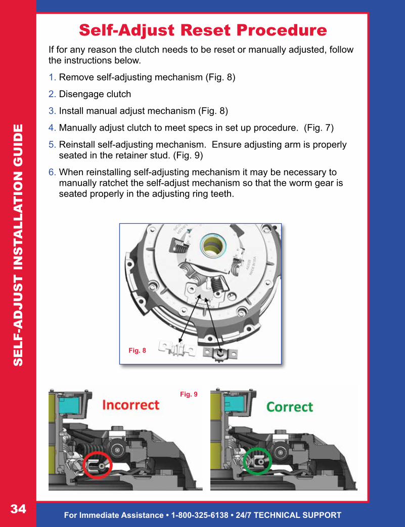
Self-Adjust Reset ProcedureIf for any reason the clutch needs to be reset or manually adjusted, follow the instructions below.
1. Remove self-adjusting mechanism (Fig. 8)
2. Disengage clutch
3. Install manual adjust mechanism (Fig. 8)
4. Manually adjust clutch to meet specs in set up procedure. (Fig. 7)
5. Reinstall self-adjusting mechanism. Ensure adjusting arm is properly seated in the retainer stud. (Fig. 9)
6. When reinstalling self-adjusting mechanism it may be necessary to manually ratchet the self-adjust mechanism so that the worm gear is seated properly in the adjusting ring teeth.
Fig. 9
Fig. 8
SE
LF-A
DJU
ST
IN
STA
LLA
TIO
N G
UID
E
ACE-MFG.COM • [email protected]
Maintenance Tips
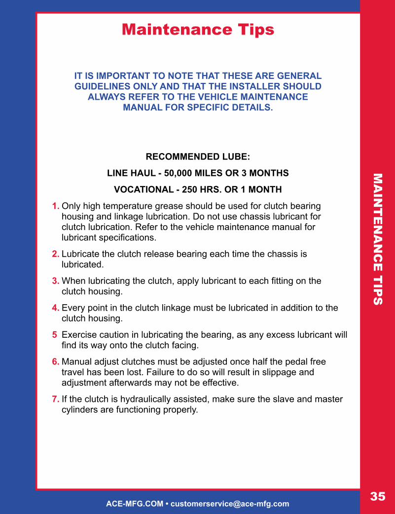
IT IS IMPORTANT TO NOTE THAT THESE ARE GENERAL GUIDELINES ONLY AND THAT THE INSTALLER SHOULD
ALWAYS REFER TO THE VEHICLE MAINTENANCE MANUAL FOR SPECIFIC DETAILS.
RECOMMENDED LUBE:
LINE HAUL - 50,000 MILES OR 3 MONTHS
VOCATIONAL - 250 HRS. OR 1 MONTH
1. Only high temperature grease should be used for clutch bearing housing and linkage lubrication. Do not use chassis lubricant for clutch lubrication. Refer to the vehicle maintenance manual for lubricant specifications.
2. Lubricate the clutch release bearing each time the chassis is lubricated.
3. When lubricating the clutch, apply lubricant to each fitting on the clutch housing.
4. Every point in the clutch linkage must be lubricated in addition to the clutch housing.
5 Exercise caution in lubricating the bearing, as any excess lubricant will find its way onto the clutch facing.
6. Manual adjust clutches must be adjusted once half the pedal free travel has been lost. Failure to do so will result in slippage and adjustment afterwards may not be effective.
7. If the clutch is hydraulically assisted, make sure the slave and master cylinders are functioning properly.
MA
INT
EN
AN
CE
TIP
S

For Immediate Assistance • 1-800-325-6138 • 24/7 TECHNICAL SUPPORT36
TR
OU
BLE
SH
OO
TIN
G
CLUTCH SLIPPING
Probable Cause: Correction:1. Incorrect clutch adjustment 1. Re-adjust per installation instructions
2. Release mechanism binding 2. Check release mechanism and linkage. Lube if necessary.
3. Grease or oil on clutch facing 3. Replace with new clutch assembly. Find and repair cause of grease or oil contamination.
4. Worn clutch facings 4. Replace with new clutch assembly
5. Overloaded clutch – wrong application 5. Review application to ensure that proper clutch was installed.
6. Flywheel out of spec 6. Check flywheel for proper dimensions.
7. Driver foot resting on clutch pedal 7. Avoid using clutch pedal as a foot rest.
NOISY CLUTCH
Probable Cause: Correction:1. Incorrect clutch adjustment 1. Re-adjust per instructions.
2. Clutch lacks lubricant or is damaged 2. Lubricate if a zerk fitting or replace clutch assembly.
3. Flywheel pilot bearing lacks lubricant or is damaged 3. Replace with new bearings.
4. Release yoke hitting cover assembly at full release position
4. Check yoke and linkage for wear. Ensure proper adjustment of yoke and linkage.
5. Worn linkage system 5. Check linkage, cross shaft, cross shaft bushings, and yoke.
6. Flywheel out of spec 6. Check flywheel for proper dimensions.
POOR CLUTCH RELEASE
Probable Cause: Correction: 1. Clutch adjustment not correct 1. Re-check adjustment per installation instructions.
2. Flywheel pilot bearing bound in flywheel or on input shaft
2. Replace pilot bearing and insure proper seating in flywheel and tolerance to input shaft.
3. Damaged clutch release bearing 3. Replace with new clutch assembly.
4. Clutch release shaft projecting through release yoke 4. Reposition release shaft so it does not project. Check
bell housing bushings, cross shafts and release yoke for wear.
5. Release yoke hitting cover assembly at full release position
5. Check yoke and linkage for wear. Ensure proper ad-justment of yoke and linkage.
6. Clutch brake worn, damaged, missing, or not fully squeezed
6. Replace worn, damaged, or missing clutch brake. Ensure proper clutch brake squeeze. Verify .010” using feeler gauge.
7. Intermediate plate sticking on drive lugs. (14” angle spring 2 plate assemblies only)
7. Check drive pins are 90° to flywheel surface and min-imum .006” clearance between drive pins and center plate slots.
8. Pressure plate not retracting fully 8. Verify release bearing is being pulled a minimum of ½”.
9. Worn splines on input shaft of transmission 9. Replace input shaft and check disc hubs for excess wear.
10. Flywheel out of spec 10. Check flywheel for proper dimensions.
TroubleshootingClutch Operation

ACE-MFG.COM • [email protected]
CH
EC
KLIS
TChecklist
Before Removing ClutchStep One: Visually Inspect Clutch System
1. Is there any kind of contamination on the clutch? Yes No
2. Are there any missing or broken pieces? Yes No
3. Are the mounting bolts tight? Yes No
4. Is there anything causing the linkage or fork to bind or drag? Yes No
Step Two: Clutch Operation
1. Is the clutch slipping? Yes No
2. Does the clutch release? Yes No
3. Does the clutch engage and disengage smoothly? Yes No
4. Does the clutch make noise while engaged? Yes No
5. Does the clutch make noise while disengaged? Yes No
Step Three: Clutch Adjustment
1. Is the clutch adjusted properly? Yes No
a) 1/2-5/8 inch under bearing to clutch Yes No
b) 1/2-9/16 inch to clutch brake Yes No
c) 1/8 inch free travel (mechanical linkage) Yes No
2. Is the clutch brake in the truck? Yes No
a) Are tabs broken off? Yes No
3. Is a torque limiting brake installed? Yes No
a) Can it be turned using channel locks or hands? Yes No
4. Does the linkage pull the bearing a minimum of 1/2 inch? Yes No
5. Is the clutch brake squeezed properly? Yes No
a) Will a .010 feeler gauge between bearing and brake stay with the clutch depressed? Yes No
CurrentSetting
Adjust.Made
For Technical Assistance – Call 1-800-325-6138

For Immediate Assistance • 1-800-325-6138 • 24/7 TECHNICAL SUPPORT38
EN
GIN
E H
P &
TO
RQ
UE
The data listed herein has been compiled from vehicle manufacturers and other reliable sources of information and is correct to the best of our knowledge. However, Ace Manufacturing & Parts Co. Cannot assume any responsibility for the accuracy of or possible errors in this information or in any other current or future informative bulletins of this nature.
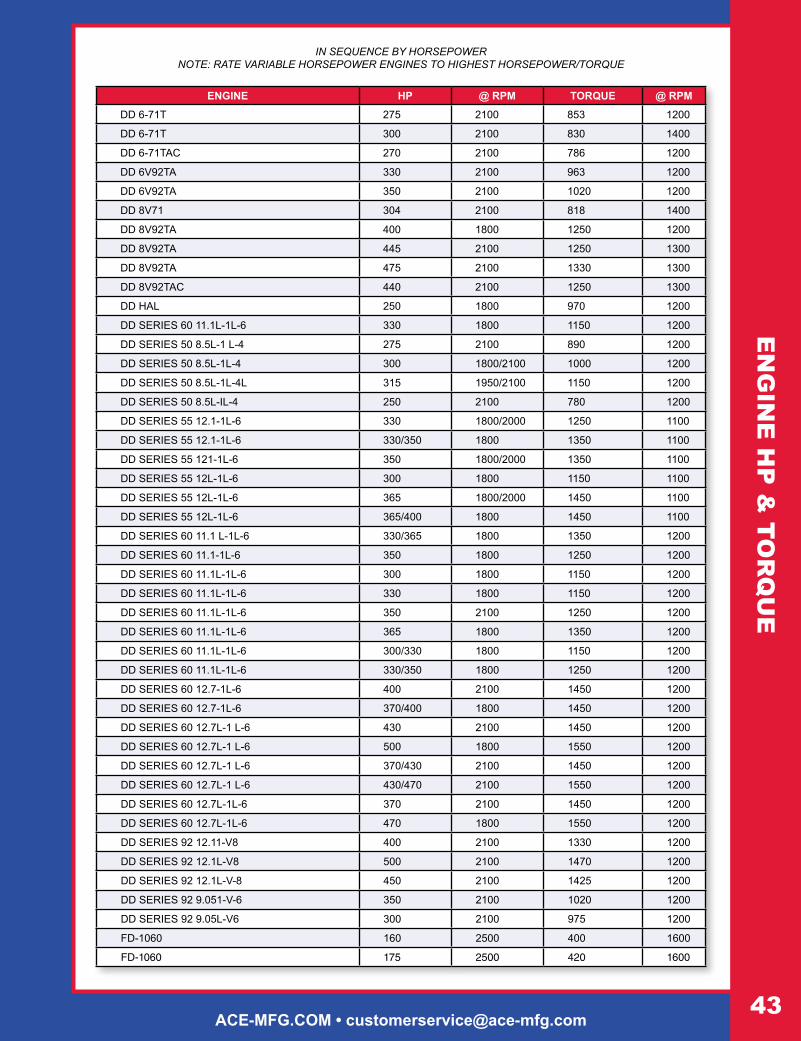
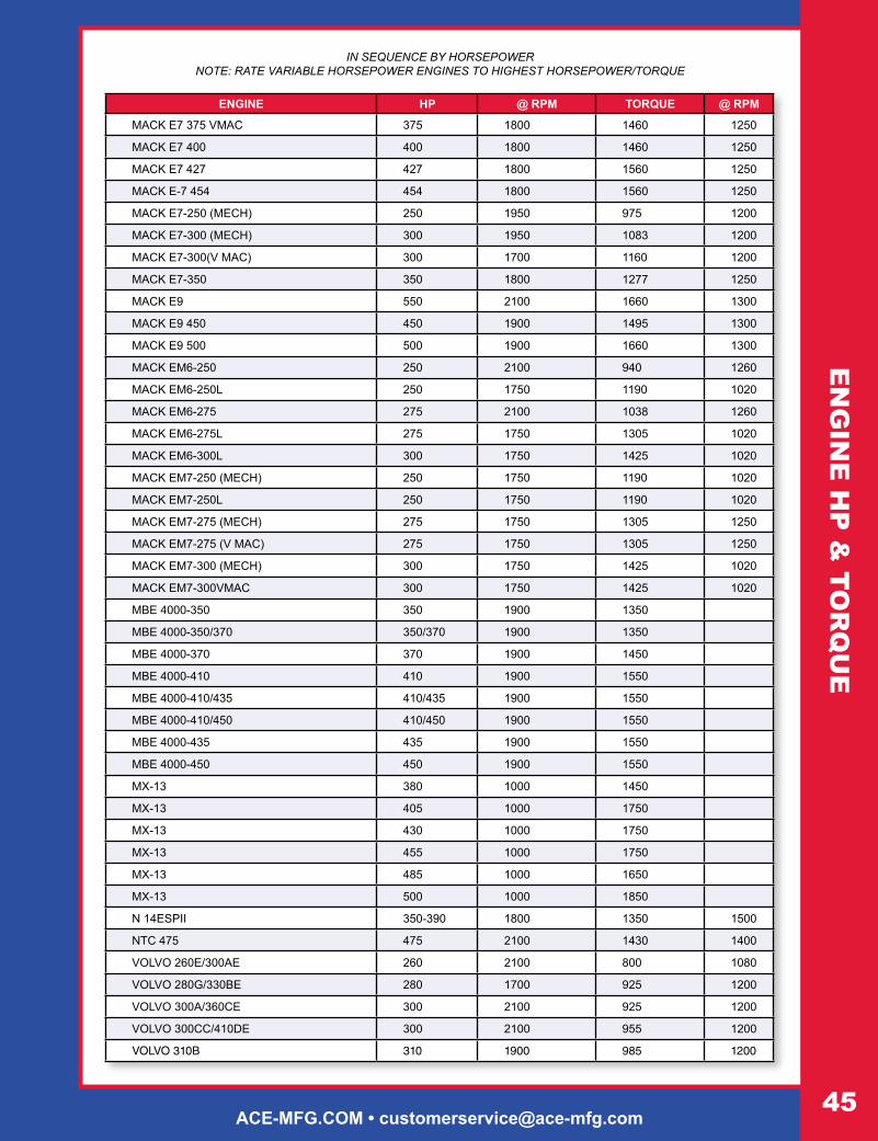
IN SEQUENCE BY HORSEPOWERNOTE: RATE VARIABLE HORSEPOWER ENGINES TO HIGHEST HORSEPOWER/TORQUE
Engine Horsepower & Torque Ratings
ENGINE HP @ RPM TORQUE @ RPM3116 195 2200 521 1560
6CTA-250 250 2200 720 1300
CAT 3066 260 1900 860 1350
CAT 3116 185 2600 520 1560
CAT 3116 215 2200 605 1560
CAT 3116 230 2200 660 1560
CAT 3116 250 2200 660 1560
CAT 3116 275 2200 750 1560
CAT 3116 (GM ‘91 UP) 215 2600 605 1560
CAT 3116 (GM MD) 275 2450 735 1560
CAT 3116 (GM-MD) 250 2600 650 1560
CAT 3116 (GM-MD) 300 2600 732 1560
CAT 3116 (HEUI) 170 2200 420 1560
CAT 3116 (MD) 170 2600 420 1560
CAT 3116 (MD) 200 2600 520 1560
CAT 3116G 185 2600 495 1560
CAT 3126 175 2400 420 1440
CAT 3126 190 2200 520 1440
CAT 3126 210 2200 605 1440
CAT 3126 230 2200 660 1440
CAT 3126 250 2200 800 1440
CAT 3126 275 2200 860 1440
CAT 3126 300 2200 860 1440
CAT 3176 ATMC 250 2100 975 1300
CAT 3176 ATMC 275 2100 1050 1200
CAT 3176 ATMC 300 2100 1150 1300
CAT 3176 ELEC 275 1800 1050 1100
CAT 3176 ELEC 275 1800 975 1100
CAT 3176 ELEC 300 1800 1050 1100
CAT 3176ATMC 325 2100 1225 1300
CAT 3176ATTMC 230 1800 975 1100
CAT 3176B 275 1800 1050 1100
CAT 3176B 300 1800 1050 1100
CAT 3176B 325 1800 1250 1200
CAT 3176B 350 1800 1350 1200
CAT 3208T (MD) 250 2600 640 1400
CAT 3208T(MD) 200 2000 620 1400
CAT 3306 245 2100 860 1350
CAT 3306 250 1800 860 1350
CAT 3306 270 2200 775 1400
CAT 3306C 300 1900 1150 1200

ACE-MFG.COM • [email protected]
EN
GIN
E H
P &
TOR
QU
EIN SEQUENCE BY HORSEPOWER
NOTE: RATE VARIABLE HORSEPOWER ENGINES TO HIGHEST HORSEPOWER/TORQUE
ENGINE HP @ RPM TORQUE @ RPM
CAT 3406 250 1600 1000 1200
CAT 3406 280 2100 1015 1200
CAT 3406 290 1800 1000 1200
CAT 3406 300 2100 1054 1200
CAT 3406 310 1800 1090 1200
CAT 3406 310 1800 1140 1100
CAT 3406 325 2100 1050 1200
CAT 3406 330 1600 1320 1200
CAT 3406 380 2100 1285 1200
CAT 3406 400 1900 1450 1250
CAT 3406 455 2100 1650 1200
CAT 3406 475 2100 1650 1750
CAT 3406 500 2100 1850 1200
CAT 3406 550 2100 1850 1200
CAT 3406 510 510 1600 1850 1200
CAT 3406B 350 2100 1320 1200
CAT 3406B 400 2100 1375 1260
CAT 3406B 425 2100 1450 1200
CAT 3406BEC 400 2100 1265 1300
CAT 3406BEC 400 1800 1375 1260
CAT 3406C 350 1800 1350 1200
CAT 3406C 425 1900 1650 1200
CAT 3406E 310 1800 1250 1200
CAT 3406E 330 1800 1350 1200
CAT 3406E 375 1800 1450 1200
CAT 3406E 410 1800 1450 1200
CAT 3406E 435 2100 1650 1200
CAT 3406E 475 2100 1750 1200
CAT 3406E 550 1800 1850 1200
CAT 3406E 600 2100 2050 1200
CAT 3406E MULTI TQ 310 1800 1150/1350 1200
CAT 3406E MULTI TQ 355 1800 1350/1450 1200
CAT 3406E MULTI TQ 375 1800 1450/1550 1200
CAT 3406E MULTI TQ 375/435 1800 1450/1550 1200
CAT 3406E(94) 355 1800 1450 1200
CAT 3406E(94) 375 1800 1550 1200
CAT 3406E(94) 410 1800 1550 1200
CAT 3406E(94) 435 1800 1650 1200
CAT 3406E(94) 475 1800 1750 1200
CAT 3406E(94) 500 1800 1850 1200
CAT 3408 420 1900 1460 1200
CAT 3408 450 2100 1460 1200
CAT 63306 CNG/LNG 235 2100 800 1200
CAT 63306 LPG (HD5) 250 2100 820 1200
CAT C-10 280 1800 1050 1100

For Immediate Assistance • 1-800-325-6138 • 24/7 TECHNICAL SUPPORT40
IN SEQUENCE BY HORSEPOWER NOTE: RATE VARIABLE HORSEPOWER ENGINES TO HIGHEST HORSEPOWER/TORQUE
ENGINE HP @ RPM TORQUE @ RPM
CAT C-10 305 2100 1150 1100
CAT C-10 325 2100 1250 1200
CAT C-10 335 1800 1350 1200
CAT C-10 350 1800 1350 1200
CAT C-10 370 1800 1350 1200
CAT C-10 MULTI 335/370 1800 1250/1350 1200
CAT C11 305 2100 1050 1200
CAT C11 335 2100 1250 2100
CAT C11 350 2100 1450 1200
CAT C11 370 2100 1450 1200
CAT C-12 355 1800 1350 1200
CAT C-12 360 2100 1350 1200
CAT C-12 380 1800 1450 1200
CAT C-12 390 2100 1450 1200
CAT C-12 410 2100 1550 1200
CAT C-12 MULTI TQ 355/410 1800 1350/1550 1200
CAT C-12 MULTI TQ 380/410 1800 1450/1550 1200
CAT C-12 RCVBUS 425 2100 1450 1200
CAT C13 305 2100 1150 1200
CAT C13 335 2100 1250 1200
CAT C13 350 2100 1550 1200
CAT C13 370 2100 1450 1200
CAT C13 380 2100 1450 1200
CAT C13 410 2100 1550 1200
CAT C13 430 2100 1650 1200
CAT C13 470 2100 1650 1200
CAT C13 MULTI TORQUE 410 2100 1450/1650 1200
CAT C13 MULTI TORQUE 430 2100 1550/1750 1200
CAT C13 MULTI TORQUE 470 2100 1550/1750 1200
CAT C15 435 2100 1650
CAT C15 475 2100 1850
CAT C15 500 2100 1850
CAT C15 550 2100 1850
CAT C15 600 2100 2050
CAT C15 625 2100 2050
CAT C15 MULTI TORQUE 435 2100 1550/1750
CAT C15 MULTI TORQUE 475 2100 1650/1750
CUM 1-10 260 1800 975 1200
CUM 1-10 270 2100 858 1400
CUM 1-10 310 310 1800 1150 1200
CUM 1-10 330E 330 1800 1250 1200
CUM 444 444 2100 1400 1500
CUM 4BT3.9 105 2500 260 1700
CUM 4BT3.9 105 2500 260 1700
CUM 4BTA3.9 120 2500 304 1700
EN
GIN
E H
P &
TO
RQ
UE

ACE-MFG.COM • [email protected]
IN SEQUENCE BY HORSEPOWER NOTE: RATE VARIABLE HORSEPOWER ENGINES TO HIGHEST HORSEPOWER/TORQUE
ENGINE HP @ RPM TORQUE @ RPM
CUM 6BT55.9 160 2500 400 1700
CUM 6BTA5.9 190 2500 475 1600
CUM 6BTA5.9 210 2500 520 1600
CUM 6BTA5.9 230 2500 605 1600
CUM 6CT8.3 210 2200 605 1500
CUM 6CTA8.3 240 2200 645 1500
CUM 6CTA8.3 250 2200 728 1500
CUM FLEET 270 270 1600 1020 1100
CUM FLEET 285 285 1600 1150 1100
CUM FLT 300 300 1700 1150 1100
CUM FORM.240 240 1800 870 1300
CUM FORM 270 270 1800 1000 1300
CUM FORM 300 300 1800 1000 1300
CUM FORM 315 315 1800 1150 1300
CUM FORM 350(90) 350 1800 1175 1300
CUM FORM 350(90) 350 1800 1200 1300
CUM FORM 365(90) 365 1800 1325 1300
CUM FORM 400 400 1800 1250 1300
CUM FORM 450 450 1900 1420 1300
CUM FORM L10-240 240 1400 858 1300
CUM FORM VT-350 300 2100 860 1400
CUM ISX15 400 400 1100 1450
CUM ISX15 425 425 1100 1650
CUM ISX15 450 450 1100 1650
CUM ISX15 485 485 1200 1850
CUM ISX15 500 500 1200 1850
CUM ISX15 525 525 1200 1850
CUM ISX15 550 550 1200 2050
CUM ISX15 600 600 1200 2050
CUM KT 450 450 2100 1350 1500
CUM KT 525 (1983) 525 2100 1650 1300
CUM KTA 600 (1983) 600 2100 1650 1600
CUM L10 270 1900 858 1300
CUM L10 300 2100 950 1300
CUM L10 FORM 300 1900 950 1300
CUM L-10 STC 12CGA 260 1600 975 1200
CUM L-10 STC 12CGB 260 1700 975 1200
CUM L-10 STC 12CGC 280 1600 1050 1200
CUM L-10 STC 12CGD 280 1700 1050 1200
CUM L-10 STC 12CGG 310 1600 1150 1200
CUM L-10 STC 12CGH 300 1700 1150 1200
CUM L10-240 240 1900 870 1300
CUM M-11 400 1800 1450 1200
CUM M11 31 OE 310 2000 1150 1200
CUM M11 330E 330 2000 1350 1200
EN
GIN
E H
P &
TOR
QU
E

For Immediate Assistance • 1-800-325-6138 • 24/7 TECHNICAL SUPPORT42
IN SEQUENCE BY HORSEPOWER NOTE: RATE VARIABLE HORSEPOWER ENGINES TO HIGHEST HORSEPOWER/TORQUE
ENGINE HP @ RPM TORQUE @ RPM
CUM M11 370 370 2000 1350 1200
CUM M11ESP11 310-370 1800 1150 1350
CUM MII 280E CELECT 280 2000 1050 1200
CUM N14 12 CEC 370 1600 1400 1200
CUM N14 310 310 1800 1150 1350
CUM N14 330E 330 2100 1350 1200
CUM N14 350E 350 2100 1400 1200
CUM N14 370E 370 2100 1450 1200
CUM N14 410E 410 2100 1450 1200
CUM N14 435E 435 2100 1650 1200
CUM N14 435E 435 2100 1550 1200
CUM N14 469E 460 2100 1650 1200
CUM N14 500 500 1800 1750 1200
CUM N14 500E 500 1750 1650 1600
CUM N14 525 525 1800 1850 1200
CUM N14 CELECT 12 CDB 370 1600 1400 1100
CUM N14 CELECT 12 CDC 430 1700 1450 1100
CUM N14 CELECT 12 CDI 350 1600 1400 1100
CUM N14 CELECT 12 CDJ 460 1700 1550 1100
CUM N14 CELECT 12 CDK 310 1600 1250 1300
CUM N14 CELECT 12 CDR 310 1699 1450 1200
CUM N14 CELECT 12 CDS 330 1600 1350 1100
CUM N14 CELECT 12 CDS 370 1600 1550 1200
CUM N14 CELECT 12 CEN 410 1600 1450 1200
CUM N14 CELECT 12 CEP 430 1700 1550 1300
CUM N14 STC 12 CEE 410 1600 1450 1200
CUM N14 STC 12 CEG 410 1600 1450 1200
CUM N14 STC 12CEH 310 1600 1250 1100
CUM N14 STC 12CEJ 350 1600 1400 1100
CUM N14 STC 12CEK 350 1600 1350 1100
CUM N14EAPI 310-390 1800 1250 1450
CUM N14ESP3 400/460 1800 1450 1650
CUM NHTC-220 220 2100 644 1500
CUM NTC 315 315 1800 1150 1300
CUM NTC 350 350 2100 1120 1300
CUM NTC 365 365 1800 1320 1300
CUM NTC300 300 2100 1000 1300
CUM NTC350(90) 350 2100 1200 1300
CUM NTC400 400 2100 1250 1300
CUM NTC444XT 444 2100 1400 1500
CUM NTC-FORM400 400 1800 1325 1300
CUM PT 240 240 2100 900 1300
CUM SIGNATURE 600 600 2100 2050 1200
CUM STC 12 CEA 330 1600 1350 1100
CUM STC 12 CEB 330 1600 1350 1100
EN
GIN
E H
P &
TO
RQ
UE
ACE-MFG.COM • [email protected]
IN SEQUENCE BY HORSEPOWER NOTE: RATE VARIABLE HORSEPOWER ENGINES TO HIGHEST HORSEPOWER/TORQUE
ENGINE HP @ RPM TORQUE @ RPM
DD 6-71T 275 2100 853 1200
DD 6-71T 300 2100 830 1400
DD 6-71TAC 270 2100 786 1200
DD 6V92TA 330 2100 963 1200
DD 6V92TA 350 2100 1020 1200
DD 8V71 304 2100 818 1400
DD 8V92TA 400 1800 1250 1200
DD 8V92TA 445 2100 1250 1300
DD 8V92TA 475 2100 1330 1300
DD 8V92TAC 440 2100 1250 1300
DD HAL 250 1800 970 1200
DD SERIES 60 11.1L-1L-6 330 1800 1150 1200
DD SERIES 50 8.5L-1 L-4 275 2100 890 1200
DD SERIES 50 8.5L-1L-4 300 1800/2100 1000 1200
DD SERIES 50 8.5L-1L-4L 315 1950/2100 1150 1200
DD SERIES 50 8.5L-IL-4 250 2100 780 1200
DD SERIES 55 12.1-1L-6 330 1800/2000 1250 1100
DD SERIES 55 12.1-1L-6 330/350 1800 1350 1100
DD SERIES 55 121-1L-6 350 1800/2000 1350 1100
DD SERIES 55 12L-1L-6 300 1800 1150 1100
DD SERIES 55 12L-1L-6 365 1800/2000 1450 1100
DD SERIES 55 12L-1L-6 365/400 1800 1450 1100
DD SERIES 60 11.1 L-1L-6 330/365 1800 1350 1200
DD SERIES 60 11.1-1L-6 350 1800 1250 1200
DD SERIES 60 11.1L-1L-6 300 1800 1150 1200
DD SERIES 60 11.1L-1L-6 330 1800 1150 1200
DD SERIES 60 11.1L-1L-6 350 2100 1250 1200
DD SERIES 60 11.1L-1L-6 365 1800 1350 1200
DD SERIES 60 11.1L-1L-6 300/330 1800 1150 1200
DD SERIES 60 11.1L-1L-6 330/350 1800 1250 1200
DD SERIES 60 12.7-1L-6 400 2100 1450 1200
DD SERIES 60 12.7-1L-6 370/400 1800 1450 1200
DD SERIES 60 12.7L-1 L-6 430 2100 1450 1200
DD SERIES 60 12.7L-1 L-6 500 1800 1550 1200
DD SERIES 60 12.7L-1 L-6 370/430 2100 1450 1200
DD SERIES 60 12.7L-1 L-6 430/470 2100 1550 1200
DD SERIES 60 12.7L-1L-6 370 2100 1450 1200
DD SERIES 60 12.7L-1L-6 470 1800 1550 1200
DD SERIES 92 12.11-V8 400 2100 1330 1200
DD SERIES 92 12.1L-V8 500 2100 1470 1200
DD SERIES 92 12.1L-V-8 450 2100 1425 1200
DD SERIES 92 9.051-V-6 350 2100 1020 1200
DD SERIES 92 9.05L-V6 300 2100 975 1200
FD-1060 160 2500 400 1600
FD-1060 175 2500 420 1600
EN
GIN
E H
P &
TOR
QU
E

For Immediate Assistance • 1-800-325-6138 • 24/7 TECHNICAL SUPPORT44
IN SEQUENCE BY HORSEPOWER NOTE: RATE VARIABLE HORSEPOWER ENGINES TO HIGHEST HORSEPOWER/TORQUE
ENGINE HP @ RPM TORQUE @ RPM
FD-1060 190 2500 475 1600
FD-1060 210 2300 520 1600
FD-1060 230 2300 605 1600
FD-1460 210 2200 605 1300
FD-1460 225 2200 660 1300
FD-1460 250 2000 800 1300
FD-1460 275 1800 860 1300
FORD 7.3 HI. ALT. 165 3000 325 1600
FORD 7.3L NATASP 185 3000 360 1400
FORD 7.3L TURBO 190 3000 395 1400
GM 6.5 L NATASP 160 3400 290 1700
GM 6.5 L TURBO 190 3400 385 1700
GM 6.5L NATASP 155 3600 275 1700
GM 6.5L TURBO 180 3400 360 1700
INTL 530 250 2200 800 1300
INTL 530 275 2000 950 1300
INTL 530 275 2200 860 1300
INTL 530 300 2000 1050 1300
INTL DT 408 210 2600 520 1800
INTL DT 408 230 2600 605 1800
INTL DT 466 195 2400 520 1600
INTL DT 466 210 2400 605 1600
INTL DT 466 275 2400 800 1600
INTL DT-408 175 2600 430 1800
INTL DT-408 190 2600 485 1800
INTL DT-466 230 2400 660 1600
INTL DT-466 250 2400 660 1600
INTL T444E 160 2600 400 1500
INTL T444E 175 2600 430 1500
INTL T444E 190 2600 485 1500
L10 280 1800 1050 1200
L-10 240/250PT 240-2100 250-2200 900 1300
L10 285PT 285 2200 1020 1300
L-10 FORM 240 240 1900 860 1300
M11 ESP1 280-330 1800 1050-1250 1200
M11-280E 280 2000 1050 1200
M11350E 350 1800 1350 1200
MACK E3-190 (MECH) CAT 190 2500 475 1300
MACK E3-220 (MECH) 220 2350 627 1400
MACK E6-250 250 2100 750 1500
MACK E6-275 275 2100 1020 1200
MACK E-6-300 300 1700 1112 1200
MACK E6-350 350 1800 1277 1250
MACK E7 325 VMAC 325 1800 1260 1250
MACK E7 350 VMAC 350 1800 1250 1250
EN
GIN
E H
P &
TO
RQ
UE
ACE-MFG.COM • [email protected]
IN SEQUENCE BY HORSEPOWER NOTE: RATE VARIABLE HORSEPOWER ENGINES TO HIGHEST HORSEPOWER/TORQUE
ENGINE HP @ RPM TORQUE @ RPM
MACK E7 375 VMAC 375 1800 1460 1250
MACK E7 400 400 1800 1460 1250
MACK E7 427 427 1800 1560 1250
MACK E-7 454 454 1800 1560 1250
MACK E7-250 (MECH) 250 1950 975 1200
MACK E7-300 (MECH) 300 1950 1083 1200
MACK E7-300(V MAC) 300 1700 1160 1200
MACK E7-350 350 1800 1277 1250
MACK E9 550 2100 1660 1300
MACK E9 450 450 1900 1495 1300
MACK E9 500 500 1900 1660 1300
MACK EM6-250 250 2100 940 1260
MACK EM6-250L 250 1750 1190 1020
MACK EM6-275 275 2100 1038 1260
MACK EM6-275L 275 1750 1305 1020
MACK EM6-300L 300 1750 1425 1020
MACK EM7-250 (MECH) 250 1750 1190 1020
MACK EM7-250L 250 1750 1190 1020
MACK EM7-275 (MECH) 275 1750 1305 1250
MACK EM7-275 (V MAC) 275 1750 1305 1250
MACK EM7-300 (MECH) 300 1750 1425 1020
MACK EM7-300VMAC 300 1750 1425 1020
MBE 4000-350 350 1900 1350
MBE 4000-350/370 350/370 1900 1350
MBE 4000-370 370 1900 1450
MBE 4000-410 410 1900 1550
MBE 4000-410/435 410/435 1900 1550
MBE 4000-410/450 410/450 1900 1550
MBE 4000-435 435 1900 1550
MBE 4000-450 450 1900 1550
MX-13 380 1000 1450
MX-13 405 1000 1750
MX-13 430 1000 1750
MX-13 455 1000 1750
MX-13 485 1000 1650
MX-13 500 1000 1850
N 14ESPII 350-390 1800 1350 1500
NTC 475 475 2100 1430 1400
VOLVO 260E/300AE 260 2100 800 1080
VOLVO 280G/330BE 280 1700 925 1200
VOLVO 300A/360CE 300 2100 925 1200
VOLVO 300CC/410DE 300 2100 955 1200
VOLVO 310B 310 1900 985 1200
EN
GIN
E H
P &
TOR
QU
E

For Immediate Assistance • 1-800-325-6138 • 24/7 TECHNICAL SUPPORT46
Notes:N
OT
ES

ACE-MFG.COM • [email protected]
SALES SUPPORT DIRECTORYNAME TITLE PHONE E-MAIL
Jerry Cone Sales Manager Cell: (859) 300-4476 [email protected]
Craig Callaway Outside Sales Cell: (636) 432-2191 [email protected]
James Lawson Outside Sales Cell: (816) 305-4739 [email protected]
Steve Russom Customer Satisfaction Specialist (573) 468-1720 [email protected]
Dwayne Hoke Technical Support Specialist (573) 468-1722 [email protected]
Barb Reed Customer Satisfaction Coordinator (573) 468-1745 [email protected]
Tricha Cassidy Customer Satisfaction Specialist (573) 468-1735 [email protected]
Our 118,000 square foot manufacturing and distribution facility is located 60 miles southwest of St. Louis in Sullivan, Missouri.Ace has been providing the highest quality clutches, clutch parts and assemblies to the heavy duty industry for over 50 years.
For high quality, low cost, American made
E-Z RIDER® Clutches, CALL: 1-800-325-6138 or visit our website: www.ace-mfg.com
SCAN WITH YOUR SMARTPHONE
CO
NTA
CT
S

AN INNOVATIVE LEADER IN CLUTCH TECHNOLOGY
300 Ramsey StreetSullivan, MO 63080
U.S.A.Toll Free: 800-325-6138
Fax: 573-468-5584www.ace-mfg.com