~~e )t:omp - department of physics | oregon state...
TRANSCRIPT

CHAPTER 6, OPTICAL INSTRUMENTS
174
(Fig. 6.13) we emphasized that ray 2 ' was just an artifact Introduced to locate the final emerging rays. There actually would' not be such a ray because the objective was not suffiCiently large to pass it. If we extend ray 2' backward, we see that It doesn't intersect the objective. (The objective lens is thus acting as a stop that limits the beam.) Conversely, very few of the rays that the objective sends to Q' reach the eye because the eyepiece is not sufficiently large to pass them and refract them to the eye. (The eyepiece thus also acts as a stop. ) To the eye. then, the point Q appears much dimmer than a point on the axis, P. The object does not appear uniformly bright, but gradually shades off toward the periphery. This effect is called vignetting (Fig. 6.21 a), and while it is occasionally attractive in, say, photographic portraits, it is generally undeSirable in microscopes , telescopes, and other optical instruments.
Enlarging the eyepiece would enlarge the field of view by moving the vignetting further out; but the rays that actually reach the eye from the field's periphery would only pass through the outer parts of the lenses . Such rays are subject t o greater aberrations than the central rays. so the periphery would n ot only be darkened but also blurred.
A. Thejield lens
We redirect the rays from the periphery of the field of view so they pass through the central region of the eyepiece by Inserting another lens, called a field lens, at the in-
FIGURE 6.21
Principle of the field lens. (a) Without field lens the final image is vignetted, only the heavy part of the arrow P "0" is significantly illuminated, the intensity falling to zero at 0". (See this effect in Fig. 4.5c). (b) With a field lens the entire field is well illuminated, because the field lens bends the entire cone of rays AO' B into CO' 0, so they can reach th '2 eyepiece and the eye. (e) and (d) Photographs of the eye's view in the tw_o cases, respectively.
I
fiGURE 6.1 9
·~ ~I
.!
Schlieren photograph of shock waves in ai r that moves at supersonic speed past a sphere. The horizontal rod above the sphere measures the pressure .
FIGURE 6.20
Principle of schl~eren photography of a transparent object: (a) without knife edge, (b) with knife edge.
P
Transparent object
(a) Film
F'
Knife edge (stop)
Light from P that misses knife edge
P
. ~~e p')T:ompof rays '
Transparent object Lens
(b) Film

6 .6 FIELD OF VIEW
175
(a) (b)
(c) (d)
1 '
CHAPTER 6 , OPTICAL INSTRUMENTS
176
termediate image P'Q'. The field lens is chosen to image the objective lens at the eyepiece. This is illustrated in Figure 6.21b for the case of the microscope . Since the field lens lies right at the intermediate image P'Q', it doesn't modify it or its subsequent image-the final image still resides at P'Q". However, the rays between these images are modified by the field lens (cf Figs. 6.21a and b) S'o that all rays striking it pass through the eyepiece. Hence, the final image is brighter and more evenly iIluminate3. Rays that would have been blocked by the -stop at one or the other lens now reach the final image, so the field of view is enlarged (Figs. 6.21c and d). Because the field lens only affects the brightness of the final image but is not involved in the actual imaging, aberrations produced by this lens are not very important.
An actual optical instrument may have a field lens at each intermediate image. For example, the terrestrial telescope of Figure 6 .14 would reqUire two field lenses, at P'Q' and at P'Q". By repeating the sequence of erecting lens - field lens several tim es, such a telescope can be made qUite long. The ability to look th rough a long, relatively narrow tube but with an ample field of view is useful in several applications. One example is a cystoscope, a device that allows a doctor to examine your insides. (The cystoscope's ri gidity makes the fiber optics tech-
FIGURE 6.22
Erecting lenses (E) and field lenses (F) that may be part of a long string of lenses in a cystoscope or a periscope. Note that the full cone of rays striking the first lens emerges from the system.
nique described in Sec. 2.5B generally preferred, at least by the patient.) A cystoscope (Fig. 6.22) will usually have a long string of lenses , with every other lens serving as a field lens. The only light losses are then due to reflection and absorption at the lenses. Typically, there will be a 45° mirror near the beginning of the system to allow the doctor to see to the sides as she examines your insides. Another example is a periscope, a Similar device, but with two 45° mirrors at its ends (see the TRY IT for Sec. 2.4C). Many other optical instruments use field lenses, and we'll next examine one such instrument.
B. The projector
To project an enlarged image of a slide, or movie film, we need only illuminate the slide and place it close to the focal point of a converging lens. The lens will then image the slide on a distant screen, as noted in Section 3.4C. Aside from the problems of advancing the slide or film, the main complication of the projector is associated with the il
~ Screen
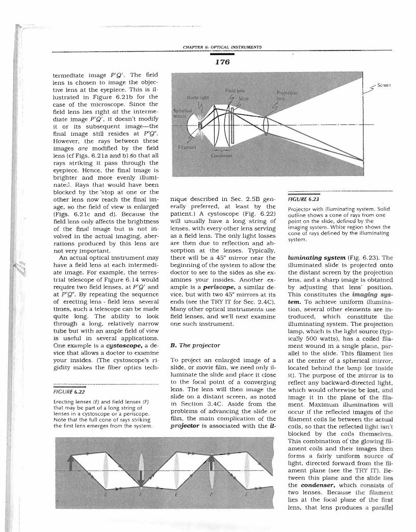
FIGURE 6.23
Projector with illuminating system. Solid outline shows a cone of rays from one point on the slide, defined by the imaging system. White region shows the cone of rays defined by the illuminating system.
lum inating system (Fig. 6 .23). The illuminated slide is projected onto the distant screen by the projection lens . and a sharp image is obta ined by adjusting that lens' position. This constitutes the imaging system. To achieve uniform illumination, several other elements are introduced, which constitute the illuminating system. The projection lamp, which is the light source (typically 500 watts), has a coiled fil ament wound in a single plane, parallel to the slide. This filament lles at the center of a spherical mirror, located behind the lamp (or inside it) . The purpose of the mirror is to reflect any backward-directed light, which would otherwise be lost. and image it in the plane of th e filament. Maximum illumination will occur if the reflected images of the filament coils lie between the actu al coils, so that the reflected ligh t Isn't blocked by the coils themselves .
E F E F £
This combination of the gloWing fil ament coils and their images then forms a fairly uniform source of light, directed forward from the filament plane (see the TRY IT). Between this plane and th e s llde lies the condenser, which consists of two lenses . Because the filament lies at the focal plane of the first lens, that lens produces a parallel

6 .6 FIELD OF VIEW
177
beam of light, which illuminates the slide uniformly Wig. 6 .24) . The second lens is the field lens. Because it lies quite close to the slide , it does not Significantly affect the uniform light Intensity near the slide, but it does focus this light to a POint close to the projection lens. By imaging the filament on the projection lens, the field lens assures that the maximum amount of light gets from the filament through the projection lens and on to the screen.
The two simultaneously coexisting systems, for illumination and for imaging, are designed to intermesh and yet to exist almost indepen dently of one another-the projection lens having little effect on (a) the illu minating system, while the field lens doesn't affect the imaging system.
Some slide projectors have a zoom lens (Sec. 4.4C) . This allows you to vary the distance between the projection lens and the slide, while still keeping the image in focus on the screen. The closer the p rojection lens Is to the slide, the larger the image on the screen. You can see this by looking at the central rays from the top and bottom of the slide in Figure 6 .25 . Without such a lens, the image size Is fixed by the distance to the screen. The zoom lens thus provides an extra degree of flexibility in the slide projector.
Overhead projectors, commonly found in lecture halls, are similar to slide projectors. Since the transparency to be projected is quite large. a large field lens is necessary, usually a Fresn el lens (Sec. 3.4D). Its rings can be seen just below the transparency. (Being so close to the transparen cy. they can easily be focused on th e screen.) Since you want to have a horizontal transparency and a vertical image. these overhead projectors have a (somewhat adjust
(b)
FICURE 6.24
Image thrown by projector (a) w ith all lenses in place, (b) with the field lens remo ved, and (c) with the entire condenser removed. Note the " keystoning" of the image.
(e)

CHAPTER 6, OPTICAL INSTRUMENTS
178
Image with long focal length
projection lens
projection lens
projection lens
fiGURE 6.25
Zoom projection lens.
able) 45° mirror either just after the projec tion lens or between its two elements.
Enlargers are basically projectors equipped with a variable st9P and exposure timing to control the amount of light projected on the print paper. The illuminating system may use a condenser or it may consist of a diffuse, uniform light source made, say, by insertIng a piece of ground glass between the lamp and the negative (the "slide"). In the latter case most of the light misses th e projection lens, but not much light intensity is needed to expose the paper.
TRY IT
FOR SECTION 6.68
The home slide projector
If you have a slide (or movie) projector, examine it (carefully!) to see the various elements described in Section 6.68. With the projector turned off, you should be able to remove the various covers that house the lamp and the condenser. Examine the lamp's filament. (If you have to remove the lamp, it is a good idea to use a handkerchief. This is particularly important if you have a quartz-halogen
Image with short focal length projection lens
lamp. Any grease or damp spots that you leave on the lamp may result in uneven heating when the lamp is later turned on, which may cause the glass to crack.) What kind of lamp is it (see Sec. 1.4C)? What is the shape of the filament? Notice whether the lamp socket requires the filament to be oriented in any particular way. Notice the curved mirror behind the lamp (built into the lamp in some cases) and, in front of the lamp, the two-lens condenser system (which might include a heat absorbing-that is, infrared absorbing-glass plate). If the filament lies in a plane, it should be parallel to the slide, and the mirror should image the filament in the spaces between the coils. To verify this, and also that the field lens images both the filament and its reflected image at the projection lens, replace the lamp and remove the projection lens by turning the focusing knob until the projection lens moves sufficiently forward so that you can gently pull it out. Now hold a piece of white paper at about the original location of the projection lens, and turn the lamp on. Look at the piece of paper from the front, rather than at the lamp directly. The filament should be imaged there, but you will not be able to make out much detail because the coils and their interlaced reflected image make a fairly uniform source. The image you see, therefore, should be a moderately uniform bright spot.
While you have the projection lens out, you may want to measure its focal length. You can then measure the lens ' diameter and compute its f-number, which you can check against the manufacturer's marking.
SUMMARY
An eye that has too strong a lens system (myopic) reqUires a diverging (negative power) eyeglass lens, which puts the far point properly at infinity. A hype ropic eye requires a converging lens to m ove the near point back to the n orm al 25 cm. Bifocal lenses have two parts, each a lens of different focal length. Astigmatism in viSion (un
equal focal lengths along d ifferent meridians) is corrected by lenses having a cylindrical component. A magnifying glass (converging lens) forms a virtual image. at a point on which you can focus. of a m uch closer object. The eyepiece of a compound microscope acts like a magnifying glass for the real image formed by the objective lens. S canning microscop es link a scanning electronic display with a scanning spot of illumination. Teles copes accept parallel light and produce a parallel beam at a d ifferent direction. Refracting astronomical telescopes produce an inverted image. Terrestrial telescopes provide erect images by means of a prism system or by a di verging eyepiece (Galilean telescope). Reflecting telescopes use concave mirrors to collect and focus ligh t. Catadioptric telescopes (such as the Schmidt telescope) combine reflecting and refracting elements. A schlieren system uses a knife edge at the focal point to block undeviated light. wh ile permitting light that has been bent to stril<e the screen. Otherwise in viSi ble objects are thereby made visible . A field lens preserves the field of View. making the Image uniformly illuminated (without vignetting ) while not changing the image-forming properties of the system. an im portant conSideration in projectors, enlargers, and most op tical instruments.

PROBLEMS
179
PROBLEMS
P1 State whether the following people (b) Indicate, with an arrow in your image P"Q" formed by two identical have normal, myopic, hyperopic, or diagram, the location of the top of the lenses LI and L2 . Redraw the figure. presbyopic vision: (a) Someone with book if its image is to be rightside up (a) Draw the cone of rays from P to P' eyeglasses of strength 3 diopters. on the screen. to P". (b) Draw the cone of rays from Q (b) Someone with eyeglasses of P9 In the viewing system of an SLR to Q'. How much of it goes on to Q "? strength - 3 diopters. (c) Someone camera, the camera lens images the (c) Pick an intermediate point M on the with bifocals. scene on the ground-glass viewing object and (in another color) draw the
P2 Repeat Problem Pl for the following screen, which is then viewed through a cone of rays from M to its intermediate people: (a) Someone with a near point small magnifying lens in the viewing image M'. Indicate, by shading that of 1 m and no accommodation window. (The mirror and pentaprism cone, which part of it reaches the final problems. (b) Someone with a near need not concern us here.) Discuss the image M". (d) To the right of M", locate point of 25 cm and a far point of function of a field lens in this system. an eye E, that can see P" but not M" infinity. (c) Someone with a near point Where would Y9U put it and what (e) Locate an eye E2 that can see both of 17 cm and a far pOint of 50 cm. would it do? (See Sec. 4.2C.) P" and M". (f) Is there any location for (d) Someone with a near point of PI0The figure shows an object PQ, an an eye E3 to see Q"? 50 cm and a far point of 1 m. intermediate image P'Q' , and a final
P3 People who have their eyelenses removed because of cataracts usually make up for this loss of focusing by Q
wearing contact lenses. In addition, they often have to wear glasses for reading. Why?
P4 When trying to measure the power of her eyeglasses, a student discovers that. the focal length she measures depends 1_._.on how she uses the light source. The p light source is a long straight filament. When it is held horizontally she measures a different focal length than when it is held vertically. What can she conclude about her eyes, and why do eyeglasses with these properties help?
P5 (a) Which lens focal length, of the following, would be best to use for a HARDER PROBLEMSmagnifying glass, assuming the only
Q"
p' J~ p"--'-1-'-' M'
Q'
concern was to get the maximum PHI Draw an eye with a rather bad myopic parallel rays) are made to appear to magnification: { = 2 cm, { = 8 cm, condition in the following way. come from P. What is the focal length {= -6 cm, { = 5 cm? (b) Why might Represent the compound lens system of the contact lens that will do this? one of the other lenses enable you to of the eye by a single thin lens. (Note particularly the sign of the focal see more detail? Represent the retina by a plane 3 cm length, i.e., whether this is a
P6 You have one each of the following behind the lens. When the eye converging or a diverging lens.) lenses, all of large diameter: { = 50 muscles are relaxed, the focal point of (e) What would the power of such a mm, { = 100 mm, { = 200 mm, this myopic lens is at F'MR' 2.5 cm contact lens be (in diopters)? { = 25 mm, {= -50 mm. Which of behind the lens, instead of on the PH] Measure your range of them would you use, and why, retina. Your job is to prescribe a accommodation in diopters and (ignoring aberrations) if you were contact lens that will correct this describe how you did it. making: (a) A magnifying glass? (b) A condition, as follows: (a) Draw a (not PH3 A certain myopic eye (when tensed) compound microscope? (c) An too large or too small) image on the has a focal length {eye = 2.45 cm, astronomical telescope? (d) A Galilean retina, where a distant object should while the distance between the lens telescope? be focused. (The exact size doesn't and retina is 3.00 cm. Eyeglasses with
P7 What does the correction plate in a matter, as you can check later by focal length {glasse, = - 20 cm (power Schmidt telescope correct? repeating the construction with a = -5 diopters) are worn 1.5 cm in
P8 An opaque projector is similar to the different size image.) (b) Use ray front of the eye. The eye views an overhead projector used in lecture tracing and the known focal point of object PQ that is 8 cm high and 30 halls, but is designed to project the relaxed myopic eye F'MR to work cm in front of it. Make a one-half opaque material (for example, a page backward and construct where an scale diagram carefully, locating the in a book) onto a screen. The basic object would have to be in order that focal pOints of the eyeglasses and the idea is to shine sufficient light on the this relaxed myopic eye would focus it eye. Draw the retina flat. Use ray book to make the book a bright on the retina. Mark the point where tracing to construct the image on the source, which can be projected by a this object would touch the axis with a retina using the two-step procedure: lens. (a) Draw a diagram showing a P. (c) Measure the distance in (a) Construct the virtual image of the design for a simple opaque projector. centimeters between P and the lens. object PQ due to the eyeglass lens, As in the overhead prOjector, the What is this distance? (d) The contact ignoring the eye. Label this virtual object (book) should be horizontal and lens to correct this myopia should be image P'Q'. (b) Treat P'Q' as the new the image (on the screen) vertical. such that rays from very far away (i.e., object, ignore the eyeglasses now, and

PROBLEMS
construct the image of P'Q' due ·to the lens system of the eye. (c) Repeat steps (a) and (b) but with the eyeglass lens 3 cm in front of the eye . (d) Compare the sizes of the images on the retina obtained in the two cases, and also compare them with the image that would have been obta ined without eyeglasses. Does the image size depend on the location of the eyeglasses? Is the image obtained with these diverging eyeglasses larger or smaller than that obtainea without eyeglasses?
PH4 Magnifying glasses can sometimes produce unusual perspective. For example, it is possible to make the farther of two identical objects look larger (instead of the usual perspective where more distant objects look smaller). Show this effect as foll ows: (a) Draw a converging lens with a 20mm focal length (the magnify ing glass). To the left of the lens draw two objects, each 10 mm high . One should be located S mm from the lens, the other 10 mm farther. (b) Use ray tracing to find the virtual image of each object as produced by the magnifying glass. Use a different color fo r each object. (c) At a distance 60
180
mm to the right of the lens, draw a pinhole to represent the pupil of the eye. (You can draw a lens there if you wish but the lens will focus the rays on the retina, so you will only need ray 2, the same ray that goes through the pinhole.) Draw a " retina" (a stra ight line) 30 mm to the right of the pinhole (or even farther if you have room on the paper). Draw a ray from the tip of the virtual image through the pinhole to the retina, for each v irtual image (s till using two colors). (d) Draw, each in its own color, the final images on the ret ina . Which is larger, the image of the closer or more distant object? (e) Without the magnifying glass, which object would produce a larger image on the retina? (If you have a magnifying glass, you can confirm your results. Look through the magnifying glass a( a match box or other small rectangular object held lengthwise. Hold the lens at arm' s length and touching one end of the match box.)
PHS (a) to (e) Repeat Problem Pl0, parts (al to (e) with a fie ld lens present. Locate this field lens at the intermediate image P'Q ' so that it images
L, on L2. (f) Locate an eye E3 that can see the entire final image P'ct'.
PH6 A better field lens than the one in Problem PHS would image L,on the pupil of the observing eye. Why would that be better?
MATHEMATICAL PROBLEMS
PM1 A certa in person has an uncorrected near point of 50 cm . What would be hi s eyeglass prescription?
PM2 A certa in person is wearing eyeglasses of strength - 3 diopters . (a) What is the farthest she can see clearly without eyeglasses ? (b) What is the closest she can see with eyeglasses, assuming her range of accommodation is normal?
PM3 A certain magnifying glass has a focal length of S cm. (a) What is its magnification ? (b) What does that mean ? Show how the lens should be held for best effect.
PM4 Using the two lenses of Problem P6 that give the greatest magnification for an astronomical telescope, calcu 'ate : (a) the magnification of that telesc Jpe; (b) the length of that telescope, frv .ll objective to eyepiece .
PMS Repeat Problem PM4 for a Galilean telescope.