e102 t&c procedure of electrical installation in gov buildings (hong kong)
TRANSCRIPT
8/4/2019 e102 T&C Procedure of Electrical Installation in Gov Buildings (Hong Kong)
http://slidepdf.com/reader/full/e102-tc-procedure-of-electrical-installation-in-gov-buildings-hong-kong 1/100
TESTING AND COMMISSIONING PROCEDURE
FOR
ELECTRICAL INSTALLATION
IN
GOVERNMENT BUILDINGS
OF
THE HONG KONG SPECIAL ADMINISTRATIVE REGION
2007 EDITION
ARCHITECTURAL SERVICES DEPARTMENT
THE GOVERNMENT OF THE HONG KONG SPECIAL ADMINISTRATIVE REGION
8/4/2019 e102 T&C Procedure of Electrical Installation in Gov Buildings (Hong Kong)
http://slidepdf.com/reader/full/e102-tc-procedure-of-electrical-installation-in-gov-buildings-hong-kong 2/100
PREFACE
This Testing and Commissioning (T & C) Procedure aims to lay down the
minimum testing and commissioning requirements to be carried out on electrical
installation in Government Buildings of the Hong Kong Special Administrative Region
(HKSAR). Such requirements are applicable to both new installations upon completion and
existing ones after major alteration.
The present edition was developed based on its 2002 edition by the Electrical
Specialist Support Group that was established under the Building Services Branch
Technical Information and Research & Development Committee. With the benefit of
information technology, electronic version of this new edition is to be viewed on and free
for download from the Architectural Services Department (ArchSD) Internet homepage. As
part of the Government’s efforts to limit paper consumption, hard copies of this T & C
Procedure will not be put up for sale.
The Architectural Services Department welcomes comments on its contents atanytime since the updating of this T & C Procedure is a continuous process to tie in with
technological advances.
8/4/2019 e102 T&C Procedure of Electrical Installation in Gov Buildings (Hong Kong)
http://slidepdf.com/reader/full/e102-tc-procedure-of-electrical-installation-in-gov-buildings-hong-kong 3/100
DISCLAIMER
This T & C Procedure is solely compiled for use on electrical installation carried
out for or on behalf of the ArchSD in Government buildings of the HKSAR.
There are no representations, either expressed or implied, as to the suitability of this
T & C Procedure for purposes other than that stated above. The material contained in this T
& C Procedure may not be pertinent or fully cover the extent of the installation in non-
government buildings. Users who choose to adopt this T & C Procedure for their works are
responsible for making their own assessments and judgement of all information contained
here. The Architectural Services Department does not accept any liability and responsibility
for any special, indirect or consequential loss or damage whatsoever arising out of or in
connection with the use of this T & C Procedure or reliance placed on it.

8/4/2019 e102 T&C Procedure of Electrical Installation in Gov Buildings (Hong Kong)
http://slidepdf.com/reader/full/e102-tc-procedure-of-electrical-installation-in-gov-buildings-hong-kong 4/100
Table of Contents
Page 1 of 5
EE_TCP
2007 Edition
TABLE OF CONTENTSPage
1. Introduction 1
2. Objectives of the Testing and Commissioning (T&C) Works 1
3. Scope of the T&C Works 2
3.1 Preliminary Steps for Testing and Commissioning (T&C)
Works
2
3.2 Testing and Inspection during Construction 2
3.3 Statutory Test and Inspection 3
3.4 Functional Performance Tests 3
3.5 Documentation and Deliverables 3
4. Testing and Commissioning (T&C) Procedures 4
4.1 Tests and Inspections during Construction 4
4.2 Statutory Inspection and Test for Low Voltage Installations 4
4.2.1 Inspection before Test 4
4.2.2 Sequence of Tests 5
4.2.3 Conductor Continuity 6
4.2.4 Insulation Resistance 7
4.2.5 Polarity 8
4.2.6 Earth Electrode Resistance 8
4.2.7 Earth Fault Loop Impedance 9
4.2.8 Functions of All Devices including Protective Devices 9
4.2.9 Additional Check for Installation in Hazardous
Environment
10
4.3 Statutory Inspection and Test for High Voltage Installations 11
4.3.1 Inspection before Test 11
4.3.2 Safety 11
4.3.3 Testing Requirements 11
4.4 Functional Test of System /Equipment 11
4.4.1 Lightning Protection System 11
4.4.2 Circuitry Check 12
8/4/2019 e102 T&C Procedure of Electrical Installation in Gov Buildings (Hong Kong)
http://slidepdf.com/reader/full/e102-tc-procedure-of-electrical-installation-in-gov-buildings-hong-kong 5/100
Table of Contents
Page 2 of 5
EE_TCP
2007 Edition
TABLE OF CONTENTSPage
4.4.3 Charger and Battery Set 12
4.4.4 Lighting Installation 13
4.4.5 Digital Multifunction Power Meter 14
4.4.6 Digital Power Analyzer 14
4.4.7 Busbar Trunking System 15
4.4.8 Equipment and Appliances 15
4.4.9 Any Other Tests that are Considered Necessary to
Meet the Design Intent
15
4.5 Assessment of Any Characteristics of Equipment Likely to have
Harmful Effects
16
4.6 Test and Inspection for Low Voltage Cubicle Switchboard 16
4.6.1 Visual Inspection 16
4.6.2 Site Test before Connection of Incoming Supply 17
4.6.3 Site Test after Connection of Incoming Supply 18
4.7 Power Energization 18
4.7.1 Notification of Completion 18
4.7.2 Preliminary Steps for Power Energization 19
4.7.3 Switch On Process 19
4.8 Calibrated Equipment 20
Annex
Annex I Testing and Commissioning Certificate on Electrical Installation
Annex II Testing and Commissioning Progress Chart for Electrical Installation
Annex III Testing and Commissioning Certificate on Low Voltage CubicleSwitchboard (LVSB) Installation
Annex IV Testing and Commissioning Progress Chart for Low Voltage Cubicle
Switchboard (LVSB) Installation
8/4/2019 e102 T&C Procedure of Electrical Installation in Gov Buildings (Hong Kong)
http://slidepdf.com/reader/full/e102-tc-procedure-of-electrical-installation-in-gov-buildings-hong-kong 6/100
Table of Contents
Page 3 of 5
EE_TCP
2007 Edition
TABLE OF CONTENTSPage
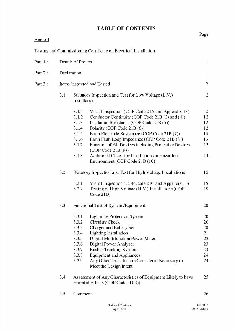
Annex I
Testing and Commissioning Certificate on Electrical Installation
Part 1 : Details of Project 1
Part 2 : Declaration 1
Part 3 : Items Inspected and Tested 2
3.1 Statutory Inspection and Test for Low Voltage (L.V.)
Installations
2
3.1.1 Visual Inspection (COP Code 21A and Appendix 13) 2
3.1.2 Conductor Continuity (COP Code 21B (3) and (4)) 123.1.3 Insulation Resistance (COP Code 21B (5)) 12
3.1.4 Polarity (COP Code 21B (6)) 12
3.1.5 Earth Electrode Resistance (COP Code 21B (7)) 13
3.1.6 Earth Fault Loop Impedance (COP Code 21B (8)) 13
3.1.7 Function of All Devices including Protective Devices
(COP Code 21B (9))
13
3.1.8 Additional Check for Installations in Hazardous
Environment (COP Code 21B (10))
14
3.2 Statutory Inspection and Test for High Voltage Installations 15
3.2.1 Visual Inspection (COP Code 21C and Appendix 13) 15
3.2.2 Testing of High Voltage (H.V.) Installations (COP
Code 21D)
19
3.3 Functional Test of System /Equipment 20
3.3.1 Lightning Protection System 20
3.3.2 Circuitry Check 20
3.3.3 Charger and Battery Set 20
3.3.4 Lighting Installation 213.3.5 Digital Multifunction Power Meter 22
3.3.6 Digital Power Analyzer 23
3.3.7 Busbar Trunking System 23
3.3.8 Equipment and Appliances 24
3.3.9 Any Other Tests that are Considered Necessary to
Meet the Design Intent
24
3.4 Assessment of Any Characteristics of Equipment Likely to have
Harmful Effects (COP Code 4D(3))
25
3.5 Comments 26

8/4/2019 e102 T&C Procedure of Electrical Installation in Gov Buildings (Hong Kong)
http://slidepdf.com/reader/full/e102-tc-procedure-of-electrical-installation-in-gov-buildings-hong-kong 7/100
Table of Contents
Page 4 of 5
EE_TCP
2007 Edition
TABLE OF CONTENTSPage
Part 4 : Test Record attached to the Test Certificate 27
4.1 Test for Low Voltage (L.V.) Installations 27
4.2 Test for High Voltage (H.V.) Installations 27
4.3 Functional Test for System /Equipment 27
4.4 Testing Equipment 27
Annex II
Testing and Commissioning Progress Chart for Electrical Installation

8/4/2019 e102 T&C Procedure of Electrical Installation in Gov Buildings (Hong Kong)
http://slidepdf.com/reader/full/e102-tc-procedure-of-electrical-installation-in-gov-buildings-hong-kong 8/100
Table of Contents
Page 5 of 5
EE_TCP
2007 Edition
TABLE OF CONTENTSPage
Annex III
Testing and Commissioning Certificate on Low Voltage Cubicle Switchboard
(LVSB) Installation
Part 1 : Details of Project 1
Part 2 : Declaration 1
Part 3 : Items Inspected and Tested 2
3.1 Visual Inspection 2
3.2 Site Tests 6
3.3 Any Other Tests that are Considered Necessary to Meet the
Design Intent
7
3.4 Comments 8
Part 4 : Test Record attached to the Test Certificate 9
4.1 Test Before Connection of Incoming Supply 9
4.2 Functional Test of All Devices 9
4.3 Test After Connection of Incoming Supply 9
4.4 Testing Equipment 9
Annex IV
Testing and Commissioning progress chart for Low Voltage Cubicle Switchboard
Installation
8/4/2019 e102 T&C Procedure of Electrical Installation in Gov Buildings (Hong Kong)
http://slidepdf.com/reader/full/e102-tc-procedure-of-electrical-installation-in-gov-buildings-hong-kong 9/100
Page 1 of 21
EE_TCP
2007 Edition
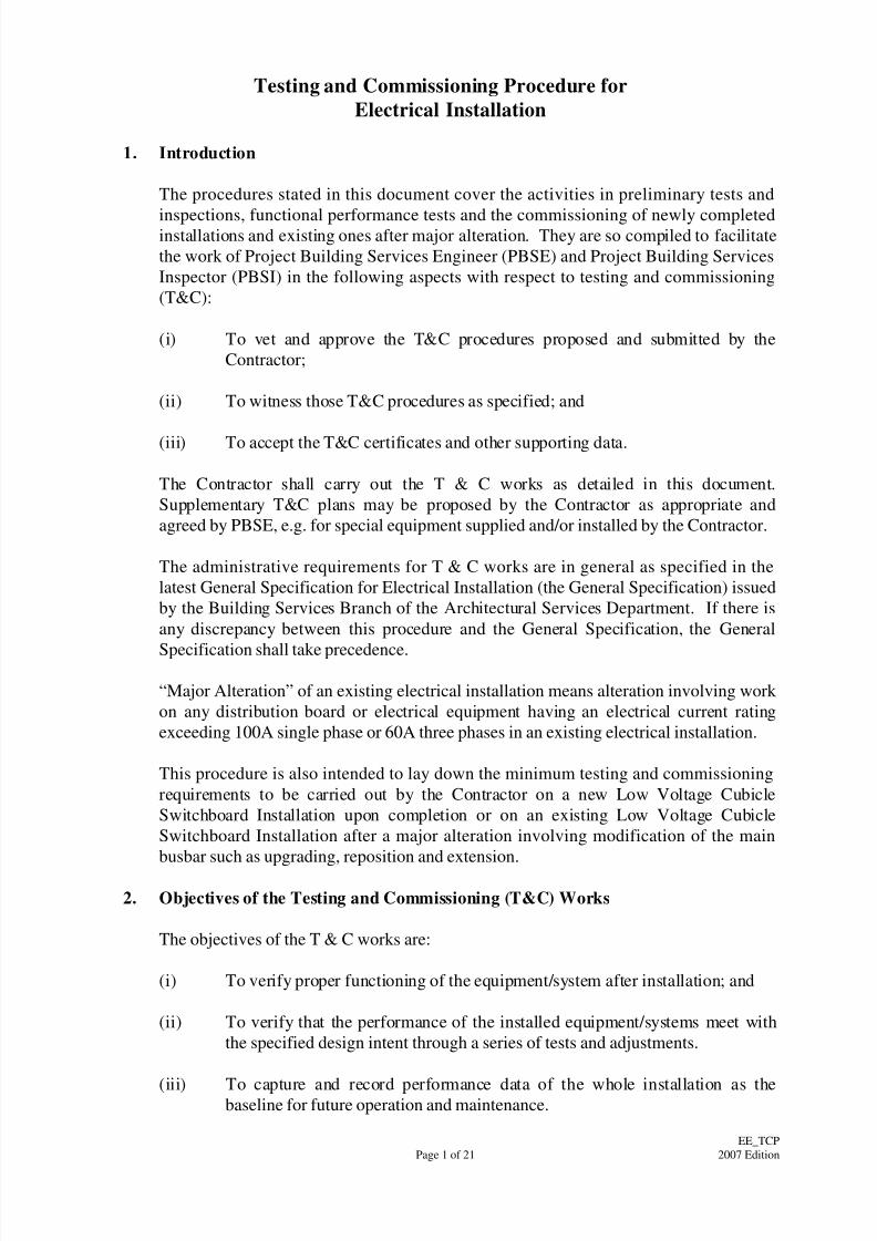
Testing and Commissioning Procedure for
Electrical Installation
1. Introduction
The procedures stated in this document cover the activities in preliminary tests and
inspections, functional performance tests and the commissioning of newly completedinstallations and existing ones after major alteration. They are so compiled to facilitate
the work of Project Building Services Engineer (PBSE) and Project Building Services
Inspector (PBSI) in the following aspects with respect to testing and commissioning
(T&C):
(i) To vet and approve the T&C procedures proposed and submitted by the
Contractor;
(ii) To witness those T&C procedures as specified; and
(iii) To accept the T&C certificates and other supporting data.
The Contractor shall carry out the T & C works as detailed in this document.
Supplementary T&C plans may be proposed by the Contractor as appropriate and
agreed by PBSE, e.g. for special equipment supplied and/or installed by the Contractor.
The administrative requirements for T & C works are in general as specified in the
latest General Specification for Electrical Installation (the General Specification) issued
by the Building Services Branch of the Architectural Services Department. If there is
any discrepancy between this procedure and the General Specification, the General
Specification shall take precedence.
“Major Alteration” of an existing electrical installation means alteration involving work
on any distribution board or electrical equipment having an electrical current rating
exceeding 100A single phase or 60A three phases in an existing electrical installation.
This procedure is also intended to lay down the minimum testing and commissioning
requirements to be carried out by the Contractor on a new Low Voltage Cubicle
Switchboard Installation upon completion or on an existing Low Voltage Cubicle
Switchboard Installation after a major alteration involving modification of the main
busbar such as upgrading, reposition and extension.
2. Objectives of the Testing and Commissioning (T&C) Works
The objectives of the T & C works are:
(i) To verify proper functioning of the equipment/system after installation; and
(ii) To verify that the performance of the installed equipment/systems meet with
the specified design intent through a series of tests and adjustments.
(iii) To capture and record performance data of the whole installation as thebaseline for future operation and maintenance.

8/4/2019 e102 T&C Procedure of Electrical Installation in Gov Buildings (Hong Kong)
http://slidepdf.com/reader/full/e102-tc-procedure-of-electrical-installation-in-gov-buildings-hong-kong 10/100
Page 2 of 21
EE_TCP
2007 Edition
For the avoidance of doubt, depending on the specific demands of individual
installation, the PBSE may require additional or substitute T & C works in regard to any
elements in the installation other than those indicated in this Procedure.
3. Scope of the Testing and Commissioning (T&C) Works
3.1 Preliminary Steps for Testing and Commissioning
Before carrying out T&C, the Contractor shall take the following steps:
(a) Submit draft T&C procedures to the PBSE for approval. The draft
T&C procedures shall include essential procedures mentioned in this
procedure plus additional T&C procedures required for specific
installations as well as manufacturer’s recommendation;
(b) Obtain design drawings and specifications and to be thoroughly
acquainted with the design intent;
(c) Obtain copies of approved shop drawings and equipment schedules;
(d) Review approved shop drawings and equipment schedules;
(e) Check manufacturer’s operating instructions and statutory
requirements;
(f) Physically inspect the installation and equipment to determine
variations from designs and/or specifications.
(g) Check individual components, e.g. key switches, control equipment,
circuit breaker status, etc. for proper position and settings for
completeness of installation.
(h) Check inclusion of manufacturer’s typical equipment testing data or
factors before T&C of particular equipment.
3.2 Testing and Inspection during Construction
The purpose of these tests is to ensure that all components and systems are in asatisfactory and safe condition before start up. Preliminary adjustment and
setting of equipment at this stage shall also be carried out at the same time to
pave way for the coming functional performance tests.
Before carrying out any test, the Contractor shall ensure that the installation
complies with all relevant statutory requirements and regulations. The T&C
works shall comply with all site safety regulatory requirements currently in
force, including but not limited to:
(i) Electricity Ordinance, Chapter 406, and other subsidiary legislation
herein;
8/4/2019 e102 T&C Procedure of Electrical Installation in Gov Buildings (Hong Kong)
http://slidepdf.com/reader/full/e102-tc-procedure-of-electrical-installation-in-gov-buildings-hong-kong 11/100
Page 3 of 21
EE_TCP
2007 Edition
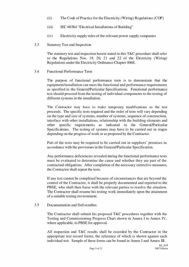
(ii) The Code of Practice for the Electricity (Wiring) Regulations (COP)
(iii) IEC 60364 “Electrical Installations of Building”
(iv) Electricity supply rules of the relevant power supply companies
3.3 Statutory Test and Inspection
The statutory test and inspection herein stated in this T&C procedure shall refer
to the Regulations Nos. 19, 20, 21 and 22 of the Electricity (Wiring)
Regulations under the Electricity Ordinance Chapter 406E.
3.4 Functional Performance Tests
The purpose of functional performance tests is to demonstrate that the
equipment/installation can meet the functional and performance requirements
as specified in the General/Particular Specifications. Functional performance
test should proceed from the testing of individual components to the testing of different systems in the installation.
The Contractor may have to make temporary modifications as the test
proceeds. The specific tests required and the order of tests will vary depending
on the type and size of systems, number of systems, sequence of construction,
interface with other installations, relationship with the building elements and
other specific requirements as indicated in the General/Particular
Specifications. The testing of systems may have to be carried out in stages
depending on the progress of work or as proposed by the Contractor.
Part of the tests may be required to be carried out in suppliers’ premises in
accordance with the provisions in the General/Particular Specification.
Any performance deficiencies revealed during the functional performance tests
must be evaluated to determine the cause and whether they are part of the
contractual obligations. After completion of the necessary corrective measures,
the Contractor shall repeat the tests.
If any test cannot be completed because of circumstances that are beyond the
control of the Contractor, it shall be properly documented and reported to the
PBSE, who shall then liaise with the relevant parties to resolve the situation.The Contractor shall resume his testing work immediately upon the attainment
of a suitable testing environment.
3.5 Documentation and Deliverables
The Contractor shall submit his proposed T&C procedures together with the
Testing and Commissioning Progress Chart shown in Annex I to Annex IV,
where applicable, to PBSE for approval.
All inspection and T&C results shall be recorded by the Contractor in the
appropriate test record forms, the reference of which is shown against each
individual test. Sample of these forms can be found in Annex I and Annex III.
8/4/2019 e102 T&C Procedure of Electrical Installation in Gov Buildings (Hong Kong)
http://slidepdf.com/reader/full/e102-tc-procedure-of-electrical-installation-in-gov-buildings-hong-kong 12/100
Page 4 of 21
EE_TCP
2007 Edition
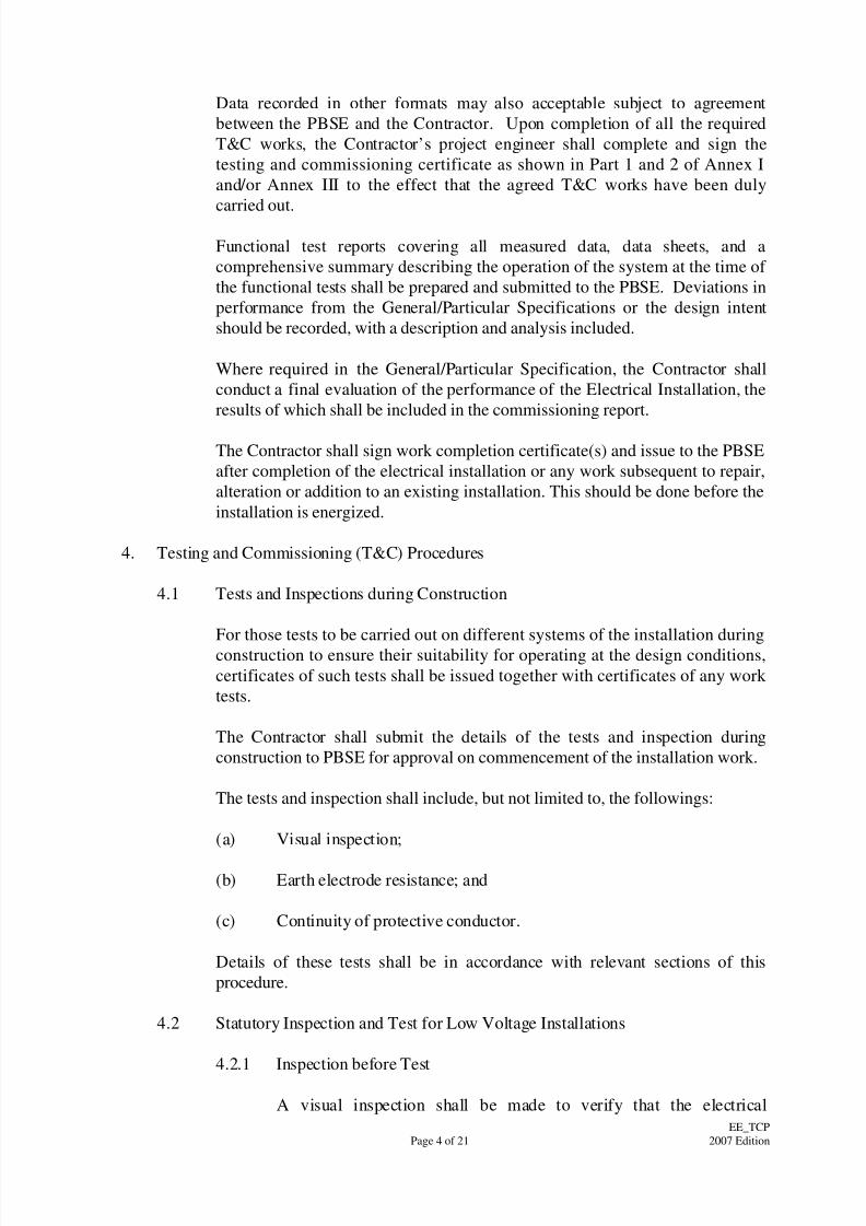
Data recorded in other formats may also acceptable subject to agreement
between the PBSE and the Contractor. Upon completion of all the required
T&C works, the Contractor’s project engineer shall complete and sign the
testing and commissioning certificate as shown in Part 1 and 2 of Annex I
and/or Annex III to the effect that the agreed T&C works have been duly
carried out.
Functional test reports covering all measured data, data sheets, and a
comprehensive summary describing the operation of the system at the time of
the functional tests shall be prepared and submitted to the PBSE. Deviations in
performance from the General/Particular Specifications or the design intent
should be recorded, with a description and analysis included.
Where required in the General/Particular Specification, the Contractor shall
conduct a final evaluation of the performance of the Electrical Installation, the
results of which shall be included in the commissioning report.
The Contractor shall sign work completion certificate(s) and issue to the PBSE
after completion of the electrical installation or any work subsequent to repair,
alteration or addition to an existing installation. This should be done before the
installation is energized.
4. Testing and Commissioning (T&C) Procedures
4.1 Tests and Inspections during Construction
For those tests to be carried out on different systems of the installation during
construction to ensure their suitability for operating at the design conditions,
certificates of such tests shall be issued together with certificates of any work
tests.
The Contractor shall submit the details of the tests and inspection during
construction to PBSE for approval on commencement of the installation work.
The tests and inspection shall include, but not limited to, the followings:
(a) Visual inspection;
(b) Earth electrode resistance; and
(c) Continuity of protective conductor.
Details of these tests shall be in accordance with relevant sections of this
procedure.
4.2 Statutory Inspection and Test for Low Voltage Installations
4.2.1 Inspection before Test
A visual inspection shall be made to verify that the electrical
8/4/2019 e102 T&C Procedure of Electrical Installation in Gov Buildings (Hong Kong)
http://slidepdf.com/reader/full/e102-tc-procedure-of-electrical-installation-in-gov-buildings-hong-kong 13/100
Page 5 of 21
EE_TCP
2007 Edition
installation /equipment as installed is correctly selected and erected in
accordance with the COP Code 21A and COP Appendix 13, and that
there is no apparent damage. The visual inspection shall include a
check on the following items, where appropriate:
(a) Adequacy of working space, access, and maintenance
facilities;
(b) Connections of conductors;
(c) Identification of conductors;
(d) Adequacy of the sizes of conductor in relation to current
carrying capacity and voltage drop;
(e) Correct connections of all equipment with special attention to
socket outlets, lampholders, isolators, switches, residual
current devices, miniature circuit breakers, and protectiveconductors,
(f) Presence of fire barriers and protection against thermal
effects;
(g) Methods of protection against direct contact with live parts
(including measurement of distances where appropriate), i.e.
protection by insulation of live parts, or protection by barriers
or enclosures;
(h) Presence of appropriate devices for isolation and switching;
(i) Choice and setting of protective and indicative devices;
(j) Labelling of circuits, fuses, protective devices, switches,
isolators and terminals;
(k) Selection of equipment and protective measures appropriate to
adverse environmental conditions;
(l) Presence of danger and warning notices;
(m) Presence of diagrams, instructions and other similar
information;
(n) Connection of single pole devices for protection or switching
in phase conductors only;
(o) Method of protection against indirect contact;
(p) Prevention of mutual detrimental influence;
(q) Presence of undervoltage protective devices;
8/4/2019 e102 T&C Procedure of Electrical Installation in Gov Buildings (Hong Kong)
http://slidepdf.com/reader/full/e102-tc-procedure-of-electrical-installation-in-gov-buildings-hong-kong 14/100
Page 6 of 21
EE_TCP
2007 Edition
(r) Erection method; and
(s) Any other appropriate inspection as listed in COP Appendix
13.
4.2.2 Sequence of Tests
The following items, where relevant, are to be tested preferably in the
sequence indicated below:
(a) Continuity of protective conductors, including main and
supplementary equipotential bonding,
(b) Continuity of ring final circuit conductors,
(c) Insulation resistance,
(d) Polarity,
(e) Earth electrode resistance,
(f) Earth fault loop impendance,
(g) Functions of all protective devices,
(h) Functions of all items of equipment.
In the event of any test indicating failure to comply, that test and those
preceding, the results of which may have been influenced by the fault
indicated, shall be repeated after the fault has been rectified.
4.2.3 Conductor Continuity
(a) Continuity of Protective Conductors
The test shall be in accordance with COP Code 21B (3).
Every protective conductor, including all conductors and anyextraneous conductive parts used for equipotential bonding
should be tested for continuity. The test should be made by
connecting together the neutral and protective conductors at
the mains position and checking between earth and neutral at
every outlet by a continuity tester, which should show a
reading near zero.
(b) Continuity of Ring Final Circuit
The test shall be in accordance with COP Code 21B (4).
The ring circuit should be tested from the distribution board.

8/4/2019 e102 T&C Procedure of Electrical Installation in Gov Buildings (Hong Kong)
http://slidepdf.com/reader/full/e102-tc-procedure-of-electrical-installation-in-gov-buildings-hong-kong 15/100
Page 7 of 21
EE_TCP
2007 Edition
The ends of the two cables forming the phase conductor
should be separated, and a continuity test should show a
reading near zero between the two; the same tests to be made
between the two cables that form the neutral conductor, and
between the two cables that form the protective conductor.
The testing method in above paragraph is only applicable
when the ring circuit has been inspected throughout, prior to
the test, to ascertain that no interconnection (multi-loops)
exists on the ring circuit. Otherwise, the testing methods
stipulated in Part 3 of the Guidance Note 3 to BS7671, should
be adopted instead.
4.2.4 Insulation Resistance
The test shall be in accordance with COP Code 21B (5).
A suitable direct current (d.c.) insulation tester should be used tomeasure insulation resistance. Care should be taken to ensure that the
insulation of the equipment under test could withstand the test voltage
without damage.
To carry out this test, it is acceptable to divide large installation into
sections with groups of outlets, each group containing not less than 50
outlets. The term outlet in this case includes every point and
every switch. A socket outlet or appliance or luminaire incorporating a
switch is regarded as one outlet.
When measured with all fuse links in place, all switches and circuit
breakers (including, if practicable, the main switch) closed and all
poles or phases of the wiring electrically connected together, the
insulation resistance to earth should not be less than the appropriate
values given in Table 21 (1) of COP. For best practice, the insulation
resistance shall not be lower than 1.0 mega ohm for low voltage
installation under a test voltage of d.c. 500V.
When measured between all conductors connected to any one phase or
pole of the supply and, in turn, all conductors connected to each other
phase or pole, the insulation resistance should not be less than theappropriate values in Table 21(1) of COP. For best practice, the
insulation resistance shall not be lower than 1.0 mega ohm for low
voltage installation under a test voltage of d.c. 500V.
For the sake of enhanced safety, when the value of insulation
resistance measured is near the minimum values as required in this
T&C procedure, or at a relatively low valves where considered
abnormal to trade’s practice, the concerned circuit /installation shall be
re-checked to improve and re-test shall be conducted afterward.
In carrying out the test:

8/4/2019 e102 T&C Procedure of Electrical Installation in Gov Buildings (Hong Kong)
http://slidepdf.com/reader/full/e102-tc-procedure-of-electrical-installation-in-gov-buildings-hong-kong 16/100
Page 8 of 21
EE_TCP
2007 Edition
(a) wherever practicable, all lamps should be removed and all
current using equipment should be disconnected and all local
switches controlling lamps or other equipment should be
closed;
(b) where the removal of lamps and/or the disconnection of
current using equipment is impracticable, the local switches
controlling such lamps and/or equipment should be open;
(c) electronic devices connected in the installation should be
isolated or short circuited where appropriate so that they are
not damaged by the test voltage.
(d) where the circuits contain voltage sensitive devices, the test
should measure the insulation resistance to earth with all live
conductors (including the neutral) connected together.
The sequence of test shall be as follows:
(1) Main switch/switchboard and outgoing circuits with sub-main
switches being isolated;
(2) Sub-main switches/switchboards and outgoing circuits with
final circuits boards being isolated; and
(3) Final circuit boards and final circuits.
Where equipment is disconnected for the test and the equipment has
exposed conductive parts require to be connected to protective
conductors, the insulation resistance between the exposed conductive
parts and all live parts of the equipment should be measured separately
and should have a minimum insulation resistance not less than 0.5
MegaOhm.
For Site Built Assemblies, the insulation applied to the live parts of
the assemblies for protection against direct contact shall be tested with
an applied voltage equivalent to that specified in the appropriate
Regulation and/ or COP for similar factory-built equipment. The
supplementary insulation of Site Built Assemblies for protectionagainst indirect contact shall be tested for degree of protection not less
than IP 2X, and the insulation enclosure shall be tested with an applied
voltage equivalent to that specified in the appropriate Regulation and
/or COP for similar factory-built equipment.
4.2.5 Polarity
The test shall be in accordance with COP Code 21B (6).
A test of polarity should be carried out to verify that:
(a) every fuse and single-pole control and protective device is

8/4/2019 e102 T&C Procedure of Electrical Installation in Gov Buildings (Hong Kong)
http://slidepdf.com/reader/full/e102-tc-procedure-of-electrical-installation-in-gov-buildings-hong-kong 17/100
Page 9 of 21
EE_TCP
2007 Edition
connected in the phase conductor only,
(b) centre-contact bayonet and Edison-type screw lampholders to
IEC 60238 in circuits having an earthed neutral conductor,
have their outer or screwed contacts connected to that neutral
conductor, and
(c) wiring has been correctly connected to socket outlets and
similar accessories.
4.2.6 Earth Electrode Resistance
The test shall be in accordance with COP Code 21B (7).
A proper earth electrode resistance tester should be used to measure
earth electrode resistance. An alternating current at 50 Hz of a steady
value is passed between the earth electrode T and an auxiliary earth
electrode T1 placed at a separation distance recommended by themanufacturer of the tester but in any case should not be less than 20
metres away. A second auxiliary earth electrode T2, which may be a
metal spike driven into the ground, is then inserted half-way between
T and T1, and the voltage drop between T and T2, divided by the
current flowing between T and T1, gives a measured earth electrode
resistance of earth electrode T.
For an electrical installation having four or more earth electrodes
which are installed more or less in line, following a general direction
not exceeding 15 deviation and with separation between adjacent
electrodes not less than the recommended distance by the
manufacturer of the tester but in any case not less than 20 metres,
these electrodes can be used in turn as the auxiliary electrodes for the
purpose of measuring the earth electrode resistances.
The following alternative method for measuring the earth electrode
resistance may be used if the electricity supply is connected. A loop
impedance tester should be connected between the phase conductor at
the origin of the installation and the earth electrode with the test link
open, and a test performed. This impedance reading could be treated
as the electrode resistance.
4.2.7 Earth Fault Loop Resistance
The test shall be in accordance with COP Code 21B (8).
The earth fault loop impedance should be measured by a phase-earth
loop tester with a scale calibrated in ohms.
The earth fault loop impedance should not exceed the requirements of
COP Code 11.
Before the test begins, it is essential to establish, by inspection, that
8/4/2019 e102 T&C Procedure of Electrical Installation in Gov Buildings (Hong Kong)
http://slidepdf.com/reader/full/e102-tc-procedure-of-electrical-installation-in-gov-buildings-hong-kong 18/100
Page 10 of 21
EE_TCP
2007 Edition
the earthing conductor and all relevant earth connections are in place,
and that the bonding connection to electricity supplier’s earthing
facilities is disconnected. Measures should be taken, during the
impedance tests especially when the earth leakage protective devices
are effectively removed for the duration of the tests, to ensure that the
installation is not being used other than by person(s) carrying out the
tests.
4.2.8 Functions of All Devices including Protective Devices
The test shall be in accordance with COP Code 21B (9).
Functional Test of Residual Current Device (RCD):
(a) Function of residual current devices should be checked by a
residual current device tester simulating an earth fault in
order to verify its effective operation. The in-built test button
should also be tested for proper functioning. One of thetesting methods is specified in subparagraph (b) and (c)
below. Other testing methods complying with relevant
national/international standards are also acceptable.
(b) The test should be made on the load side of the RCD between
the phase conductor of the protected circuit and the associated
circuit protective conductor. The load should be disconnected
during the test.
(c) For general purpose RCDs to IEC 61008 or RCBOs to
IEC61009, with a leakage current flowing equivalent to 50%
of the rated tripping current of the RCD, the device should
not open. When a leakage current is flowing equivalent to
100% of the rated tripping current of the RCD, the device
should open in less than 300 ms unless it is of Type S(or
selective) which incorporates an intentional time delay, when
it should trip within the time range from 130 ms to 500 ms.
Function of other protective devices, such as miniature circuit
breakers, moulded case circuit breakers, air circuit breakers, fused
switches, switch-fuses and protective relays etc. should be checked byhand operation as appropriate.
Function of all items of equipment such as isolators, switches and
indicative devices should be checked by hand operation.
4.2.9 Additional Check for Installation in Hazardous Environment
The following additional check, where appropriate, shall be carried out
for installations in hazardous environment in accordance with COP
Code 21B (10):
(a) Where appropriate, the area involved should be checked to

8/4/2019 e102 T&C Procedure of Electrical Installation in Gov Buildings (Hong Kong)
http://slidepdf.com/reader/full/e102-tc-procedure-of-electrical-installation-in-gov-buildings-hong-kong 19/100
Page 11 of 21
EE_TCP
2007 Edition
ensure ‘gas free’ condition before insulation and earth fault
loop impedance test are carried out.
(b) All equipment should be suitably protected according to the
types of protection under COP Code 15. The integrity of the
type of protection provided for the equipment should not be
jeopardised by the method of installation. No alteration that
may invalidate the conditions of protection can be used.
(c) Equipment should be kept clean and free from accumulation
of dust, foreign particles and deleterious substances.
Equipment is kept free from condensation.
(d) All lamps, fuses and replaceable parts should be checked so
that correct rating and types are being used.
(e) The surface temperature of all equipment should be
appropriate to the type of protection being provided.
4.3 Statutory Inspection and Test for High Voltage Installations
4.3.1 Inspection before Test
The inspection shall be in accordance with COP Code 21C.
Inspection of H.V. installations should follow those for L.V.
installations listed in section 3.5 of this procedure with additional
checks on the following items where relevant:
(a) provision of suitable locking facilities for every entry to an
H.V. switchroom/substation;
(b) continuity of protective conductors especially the bonding of
all exposed conductive parts; and
(c) provision of padlock facilities for shutters, key boxes etc.
4.3.2 Safety
Precautionary measures should be taken and the methods of tests
should be such that no danger to persons or property can occur even if
the circuit being tested is defective.
Before carrying out the T&C for high voltage installations, the
Contractor shall submit risk assessment, safety plan and
implementation procedure to PBSE for approval.
4.3.3 Testing Requirements
Testing for High Voltage installations should be referred to relevant

8/4/2019 e102 T&C Procedure of Electrical Installation in Gov Buildings (Hong Kong)
http://slidepdf.com/reader/full/e102-tc-procedure-of-electrical-installation-in-gov-buildings-hong-kong 20/100
Page 12 of 21
EE_TCP
2007 Edition
recognized standards, manufacturers’ recommendation, operations and
maintenance instructions.
The Contractor shall responsible to submit a full T&C plan with
inspection and test details to PBSE for approval.
4.4 Functional Test of System /Equipment
4.4.1 Lightning Protection System
The whole lightning protection system shall be tested for continuity
between air terminations and earthing terminations and the resistance
shall be recorded.
The earth termination resistance shall be tested and recorded. Each
earth termination shall have a resistance to earth not exceeding the
product given by 10 times the number of earth terminations to be
provided. The whole of the lightning protection system shall have acombined resistance to earth not exceeding 10.
Where the steel work of the structure is used as down conductor, the
continuity of the steel work shall be tested and recorded.
Locations of all earth electrodes and down tape routing shall be
checked to be clear of any dangerous goods store, diesel tanks and
inflammable stores, etc.
All connections at terminations, tee off points and earth electrodesshall be checked for tightness.
4.4.2 Circuitry Check
All circuits shall be verified through switching operation to ensure that
the circuits are installed in accordance with the designated circuit. The
tests shall include but not be limited to the following:
(a) on/off switching of the lighting circuit to ensure that the
lighting circuit is installed corresponding to the lighting
switch, protective device and labelling;
(b) switching of the general power circuit to ensure that the
circuit corresponds to the protective device such as RCD,
RCBO and MCB, and that the protective device performs in
accordance with the designated duty;
(c) switching of the main switch / isolator to ensure the
corresponding circuit is properly controlled by the main
switch / isolator;
(d) switching of all sub-main and main distribution circuits, e.g.
busducts, cable feeders, underground cables, etc. to ensure the
8/4/2019 e102 T&C Procedure of Electrical Installation in Gov Buildings (Hong Kong)
http://slidepdf.com/reader/full/e102-tc-procedure-of-electrical-installation-in-gov-buildings-hong-kong 21/100
Page 13 of 21
EE_TCP
2007 Edition
correct isolation of the connected circuit;
(e) switching of all changeover switches to ensure the changing
over sequence corresponds to the design criteria;
(f) ensuring all the protective devices perform properly against
the designated circuit.
4.4.3 Charger and Battery Set
The following inspections and tests shall be carried out after
completion of the installation of the respective system and the
connection of the permanent supply cable:
(a) inspection of the charger for correct connection to the mains
supply through a suitable rated fuse;
(b) inspection of the batteries proper connections;
(c) inspection of instruments, indicating lamps, fuses, relays and
labels on battery charger;
(d) for initial set-up, the batteries shall be charged at the manual
highest rate until the charging current remains constant. The
starting and finishing time are recorded. The capacity of
charger is checked for capability of recharging the batteries
from fully discharged to fully charged within the specified
duration;
(e) the charger output on load with batteries disconnected shall
be measured. This should be between 110% and 115% of the
normal batteries voltage and within the operating voltage
limits of all connected devices;
(f) the charger current on load with battery disconnected shall be
measured. This should be less than the maximum
recommended continuous charge current for the batteries;
(g) on interruption of mains input to the charger, the properoperation of connected devices on standby batteries shall be
checked. In the case of switch tripping in Switchboard, mains
input shall be interrupted to check whether the capacity of the
batteries is adequate to trip the associated air circuit breaker
consecutively at least 20 times or up to twenty air circuit
breakers simultaneously, whichever the greater;
(h) the correct function of charger fail/mains fail/battery
disconnected/boost charge/trickle charge indications as
specified shall be checked.
4.4.4 Lighting Installation
8/4/2019 e102 T&C Procedure of Electrical Installation in Gov Buildings (Hong Kong)
http://slidepdf.com/reader/full/e102-tc-procedure-of-electrical-installation-in-gov-buildings-hong-kong 22/100
Page 14 of 21
EE_TCP
2007 Edition
Lighting installation shall be tested in terms of its light quality and
control as following:
(a) Before carrying out the lighting measurement and test, all
luminaries shall be checked against the specified colour
temperature, beaming angle of spot lamp and aiming angle
for exterior floodlights.
(b) The aiming angle of external lighting or planter lighting shall
be commissioned so as not to create glare or any obstructive
light to external environment.
(c) Before commissioning and /or setting of lighting control
devices which including but not limited to timer switch,
occupancy sensor, photocell and infra-red sensor, the
Contractor shall submit commissioning /setting proposal to
PBSE for approval.
(d) Illumination level of lighting installation for individual areas
/rooms shall be measured to verify the light output. The
Contractor shall submit the proposed locations and height
levels for carrying out the measurement of illuminance level
to PBSE for approval before commencement of
measurement. Presentation of the measurement result shall be
in the form of marked up layout plan for the particular area.
(e) Base on the measured illuminance results for individual areas
/rooms, the lighting uniformity of the respective areas /rooms
shall be evaluated in terms of minimum to average
illuminance ratio and/ or any other uniformity ratio as
required by the PBSE.
(d) All grouping of luminaries shall be tested by hand operation
of the corresponding switches or timers.
(e) For lighting installation with interface connection to building
management system (BMS), or central control and
monitoring system (CCMS) or similar central computercontrol system, the Contractor shall co-ordinate with other
contractors responsible for such computer control system, if
required, to demonstrate proper control function of the
lighting installation.
4.4.5 Digital Multifunction Power Meter
The digital multifunction power meter shall be tested to verify the
measurement, recording and interfacing functions as required in the
General Specification.
Prior to the test for every digital multifunction power meter, the

8/4/2019 e102 T&C Procedure of Electrical Installation in Gov Buildings (Hong Kong)
http://slidepdf.com/reader/full/e102-tc-procedure-of-electrical-installation-in-gov-buildings-hong-kong 23/100
Page 15 of 21
EE_TCP
2007 Edition
Contractor shall provide manufacturer’s calibration certificate for each
meter for checking on the accuracy.
The Contractor shall provide testing kit to verify the reading accuracy
of the digital multifunction power meter.
For installation of digital multifunction power meter with connection
to building management system (BMS), or central control and
monitoring system (CCMS) or similar central computer monitoring
system, the Contractor shall co-ordinate with other contractor
responsible for such computer monitoring system, if required, to
demonstrate proper functioning and interfacing of the meter.
For installation of digital multifunction power meter without external
connection to building management system or CCMS, the interface
functions including digital and analogue output shall be tested by
means of plugging in communication module provided by the
Contractor.
The replacement mechanism of the meter shall be tested. The test shall
demonstrate that the replacement of the meter does not require the
switching off of the respective switchgear. Current transformers
shorting block to prevent open circuiting the current transformers shall
also be tested.
4.4.6 Digital Power Analyzer
The testing requirement for digital power analyser shall be in
accordance to section 3.9.5.
In addition to test requirement as stipulated in section 3.9.5, the event
alarm function and waveform capture function of the digital power
analyser shall also be tested. The Contractor shall propose simulated
test method for PBSE’s approval.
4.4.7 Busbar Trunking System
In general, busbar trunking system shall be certified by testing
laboratories or organizations as stated in the COP. It shall be typetested in accordance with Clause 8.1.1 of IEC 60439-2. The
verification of short-circuit strength shall be carried out by an
Independent Short Circuit Testing Organization.
Short-circuit test on the phase and neutral busbars shall be carried out
in accordance with Clause 8.2.3 of IEC 60439-1 to the value of short-
circuit current specified in the General Specification.
The busbar insulation shall be tested in accordance with Clause 8.2.2
of IEC 60439-1. All test certificates shall be presented during
inspection and testing.

8/4/2019 e102 T&C Procedure of Electrical Installation in Gov Buildings (Hong Kong)
http://slidepdf.com/reader/full/e102-tc-procedure-of-electrical-installation-in-gov-buildings-hong-kong 24/100
Page 16 of 21
EE_TCP
2007 Edition
The busbar trunking system shall also be tested to verify its continuity,
insulation resistance, polarity, earth fault loop impedance and other
parameters as appropriate after installation.
For installation of busbar trunking with long run, phase transposition
of busbar in accordance with manufacturer’s recommendation shall be
checked.
Plug-in tap-off unit of busbar trunking system shall be tested to verify
proper and safe operation. Mechanical interlock, quick fastening and
quick releasing mechanism of the tap-off unit shall be tested. Positive
earth connection of tap-off unit shall be checked.
After power energization of the busbar trunking system, infrared
scanning at connecting joints shall be carried out to check for
abnormal rise in temperature at joints. The Contractor shall submit
proposal of the test methodology and propose testing points for PBSE
approval prior to the test.
4.4.8 Equipment and Appliances
Testing on electrical equipment and appliances supplied within the
electrical installation, e.g. meters, fans, etc. shall be carried out in
accordance with the relevant sections of other Building Services
Branch Testing and Commissioning Procedures for other building
services installations and manufacturer’s recommended testing
procedures.
4.4.9 Any Other Tests that are Considered Necessary to Meet the Design
Intent
For any other system /equipment that are not covered by this T&C
Procedure, the contractor shall submit full details of testing
requirements as recommended by the relevant manufacturer to PBSE
for approval.
4.5 Assessment of Any Characteristics of Equipment Likely to have Harmful
Effects
Before carrying out the T&C, the Contractor shall conduct assessment for any
characteristics of equipment likely to have harmful effects upon other electrical
equipment or other services, or impair the supply. Those characteristics
include the following:
(a) Overvoltages;
(b) Undervoltages;
(c) Fluctuating loads;
(d) Unbalanced loads;
8/4/2019 e102 T&C Procedure of Electrical Installation in Gov Buildings (Hong Kong)
http://slidepdf.com/reader/full/e102-tc-procedure-of-electrical-installation-in-gov-buildings-hong-kong 25/100
Page 17 of 21
EE_TCP
2007 Edition
(e) Power factor;
(f) Starting currents;
(g) Harmonic currents;
(h) Direct current (d.c.) feedback;
(i) High frequency oscillations; and
(j) Necessity for additional connection to earth.
The Contractor shall, after conduct the assessment, submit an assessment report
to PBSE for consideration.
4.6 Test and Inspection for Low Voltage Cubicle Switchboard (LVSB)
The following sections stipulated the additional inspection and testing
requirements for LVSB installation. For comprehensive testing and
commissioning, the Contractor shall also refer to relevant sections of this T&C
Procedure and carry out inspection /test accordingly.
4.6.1 Visual Inspection
Visual inspection shall be carried out for the proper installation of the
LVSB Installation in accordance with the Specification. The following
components shall be included:
(a) construction of type tested assembly;
(b) main busbars and droppers/risers;
(c) air circuit breakers/fuse switches;
(d) power factor correction capacitor bank;
(e) harmonic filter;
(f) automatic Changeover Switch;
(g) instrumentation and protection devices;
(h) incoming/outgoing busbars and cables;
(i) portable earthing equipment;
(j) operating handles/keys;
(k) hydraulic truck;

8/4/2019 e102 T&C Procedure of Electrical Installation in Gov Buildings (Hong Kong)
http://slidepdf.com/reader/full/e102-tc-procedure-of-electrical-installation-in-gov-buildings-hong-kong 26/100
Page 18 of 21
EE_TCP
2007 Edition
(l) rubber insulation mat.
4.6.2 Site Test before Connection of Incoming Supply
The following tests shall be carried out on site after completion of
installation of the LVSB and before the connection of the incoming
supply cable:
(a) Dielectric Test
Dielectric test shall be carried out to verify the dielectric
properties of the LVSB. The test requirements shall be in
accordance to IEC 60439-1.
(b) Insulation Test
This shall be carried out by means of a 1000V insulation
tester or similar instrument.
(c) Secondary Injection Test
This shall be carried out using a.c. and shall check
(approximately) that protection relays or devices function in
accordance with their performance curves by a test at the
lowest setting and two further tests of current and timing.
(d) Primary Injection Test
This shall be carried out to prove the correct operation of
protective devices or system when set at the agreed setting.
(e) Polarity Check for Current Transformer (C.T.)
This shall be carried out to ensure that all C.T. are correctly
connected.
(f) Functional Test of All Devices
This shall be carried out to ensure that all devices can operateproperly as intended.
The equipment to be tested shall include, but not limited to,
all circuit breakers, isolating switches, changeover switches,
contactors, interlocking facilities, protective relays, earth
leakage tripping devices, metering facilities and instruments.
(g) Contact Resistance Test
This shall be carried out by means of "Ductor" tester or
similar instrument to ensure that contacts and joints for
switchgears, cables, busbars as well as the contacts and joints

8/4/2019 e102 T&C Procedure of Electrical Installation in Gov Buildings (Hong Kong)
http://slidepdf.com/reader/full/e102-tc-procedure-of-electrical-installation-in-gov-buildings-hong-kong 27/100
Page 19 of 21
EE_TCP
2007 Edition
for outgoing cables and busbars are maintained in good
condition.
(h) Temperature Rise Limits Test
This shall be carried out as defined in IEC 60439-1.
With the prior approval by the PBSE, the primary injection test and
temperature rise limits test can be carried out in factory due to site
constraints.
4.6.3 Site Test After Connection of Incoming Supply
The following tests shall be carried out after the incoming supply
cables are connected and the “Switchboard” successfully
commissioned on no load:
(a) phase-to-phase voltage test;
(b) phase-to-neutral voltage test;
(c) phase-to-earth voltage test;
(d) neutral-to-earth voltage test;
(e) phase sequence test on each and every outgoing circuit.
4.7 Power Energization
4.7.1 Notification of Completion
After the proper testing and commissioning of the electrical
installation, the Contractor shall notify the appropriate Authority,
through the PBSE, on the completion of the installation and its
readiness for inspection and testing.
4.7.2 Preliminary Steps for Power Energization
The followings shall be checked before power energization:
(a) busbar chambers, main and sub-main switch connections i.e.
bolts and nuts tightness;
(b) earthing connections at compartments, all switches and earth
electrodes;
(c) clearance of live parts from direct contact with or any
likelihood of contact with tools, spurious bare conductors
remaining in switches, air circuit breakers (ACB) and switch
cubicles;

8/4/2019 e102 T&C Procedure of Electrical Installation in Gov Buildings (Hong Kong)
http://slidepdf.com/reader/full/e102-tc-procedure-of-electrical-installation-in-gov-buildings-hong-kong 28/100
Page 20 of 21
EE_TCP
2007 Edition
(d) polarity, phase sequence of all switches and relevant fuse
ratings;
(e) stand-by battery supply and the operation of shunt trip
mechanism;
(f) settings of overcurrent, earth fault relays and current
transformer (C.T.) polarity;
(g) vacuum cleaning of switches and ACBs;
(h) provision of danger and warning signs.
(i) Certified Work Completion Certificate in accordance to the
requirement of COP Code 19.
4.7.3 Switch On Process
Whenever there is any break of time e.g. the next day, in carrying out
the switch on process, re-test of insulation resistance is required. The
following procedures shall be followed in the switch on process:
(a) switch on the main switch/ACB with all other sub-main
switches off;
(b) if normal, switch on other sub-main switches one by one with
all other outgoing switches off;
(c) if normal, then switch on all other out-going switches one by
one;
(d) observe the disc of the overcurrent (o/c) and earth fault
protection relays for any movement for IDMT relays or for
digital protection relays check whether there are any fault
indications;
(e) keep vigilance for about 30 minutes to see if any smell or
abnormal noise being generated.
4.8 Calibrated Equipment
4.8.1 The Contractor shall supply the calibrated equipment relevant for
T&C of the electrical installation as stipulated in the particular
specification of the contract or the General Specification whichever
appropriate. The equipment shall be calibrated by the recognized
laboratories accredited with the Hong Kong Laboratory Accreditation
Scheme (HKOLAS) or other worldwide-recognised laboratories
during the active period of the contract.
4.8.2 A list of equipment proposed by the contractor to be used for T&C
must be agreed with the PBSE prior to T&C. All equipment requiring
8/4/2019 e102 T&C Procedure of Electrical Installation in Gov Buildings (Hong Kong)
http://slidepdf.com/reader/full/e102-tc-procedure-of-electrical-installation-in-gov-buildings-hong-kong 29/100
Page 21 of 21
EE_TCP
2007 Edition
periodic calibration shall have this carried out before the work
commences. Data sheets of such testing instrument showing
manufacturer’s name, model number, latest date of calibration and
correction factors shall be submitted to the PBSE for record. If any
item requires re-checking the accuracy because of the time that has
elapsed since the previous calibration, this shall be carried out prior to
commencing the work.

8/4/2019 e102 T&C Procedure of Electrical Installation in Gov Buildings (Hong Kong)
http://slidepdf.com/reader/full/e102-tc-procedure-of-electrical-installation-in-gov-buildings-hong-kong 30/100
Annex I
Architectural Services Department Annex I Issue Date: 17 Dec 2007
BSB– Standard Form No:PBS/SR.062(2007) Page 1 of 40 Revision Date: -
EE_TCP (2007 Edition)
Building Services Branch Form No. PBS/SR.062
Testing and Commissioning Certificate on Electrical Installation
Part 1 : Detail of Project
1.1 Project title (with location) :
1.2 * P.W.P. / Project No. :
1.3 * Contract/Sub-contract/Quotation No. :
1.4 * Contractor/Sub-contractor :
1.5 PBSE :
1.6 PBSI :
Part 2 : Declaration
2.1 I certify that the Electrical Installation as specified in the *Contract/Sub
contract//Quotation at the above location has been inspected, tested and commissioned in
accordance with this procedure and/or any other procedures agreed between the PBSE
and the Contractor. The results are satisfactory in the aspects as mentioned in Part 3
and/or as recorded in Part 4 of this Certificate, except as indicated in the COMMENTS
items.
2.2 I also certify that site tests have been performed in accordance with the requirements set
out in Annex I of this procedure and that the results are satisfactory. A record of the testshas been prepared and submitted to the project BSE.
*2.3 I also certify that the lightning protection system has been inspected and tested, in
accordance with the requirements of IEC62305-1:2006.
Signature - Post :
Tel. No. :
(Name of Contractor’s
Representative)
( ) Date :
Signature - Post :
Tel. No. :
(Designation of Contractor’s
Representative)
( ) Date :
Signature - Post :
Tel. No. :(Name and Stamp of Contractor)
( ) Date :
Note : This certificate must be signed by a person authorized by the Firm/Company
* Delete if not applicable
8/4/2019 e102 T&C Procedure of Electrical Installation in Gov Buildings (Hong Kong)
http://slidepdf.com/reader/full/e102-tc-procedure-of-electrical-installation-in-gov-buildings-hong-kong 31/100
Annex I
Signature - Post :
Tel. No. :Tested / Checked by :
(Name of Contractor’s Representative)
( ) Date :
Signature - Post :
Tel. No. :Witnessed by :(Name(s) of *PBSE/PBSI)
( ) Date :
Architectural Services Department Annex I Issue Date: 17 Dec 2007
BSB– Standard Form No:PBS/SR.062(2007) Page 2 of 40 Revision Date: -
EE_TCP (2007 Edition)
Items tested /
checked by
Contractor
Items witnessed
by
PBSE/PBSI
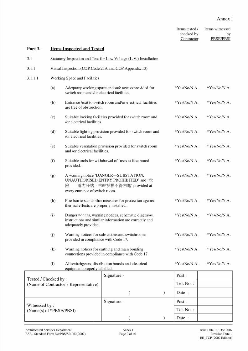
Part 3. Items Inspected and Tested
3.1 Statutory Inspection and Test for Low Voltage (L.V.) Installation
3.1.1 Visual Inspection (COP Code 21A and COP Appendix 13)
3.1.1.1 Working Space and Facilities
(a) Adequacy working space and safe access provided for
switch room and /or electrical facilities.
*Yes/No/N.A. *Yes/No/N.A.
(b) Entrance /exit to switch room and/or electrical facilities
are free of obstruction.
*Yes/No/N.A. *Yes/No/N.A.
(c) Suitable locking facilities provided for switch room and
/or electrical facilities.
*Yes/No/N.A. *Yes/No/N.A.
(d) Suitable lighting provision provided for switch room and
/or electrical facilities.
*Yes/No/N.A. *Yes/No/N.A.
(e) Suitable ventilation provision provided for switch room
and /or electrical facilities.
*Yes/No/N.A. *Yes/No/N.A.
(f) Suitable tools for withdrawal of fuses at fuse board
provided.
*Yes/No/N.A. *Yes/No/N.A.
(g) A warning notice ‘DANGER—SUBSTATION,
UNAUTHORISED ENTRY PROHIBITED’ and ‘
——’ provided at
every entrance of switch room.
*Yes/No/N.A. *Yes/No/N.A.
(h) Fire barriers and other measures for protection against
thermal effects are properly installed.
*Yes/No/N.A. *Yes/No/N.A.
(i) Danger notices, warning notices, schematic diagrams,
instructions and similar information are correctly and
adequately provided.
*Yes/No/N.A. *Yes/No/N.A.
(j) Warning notices for substations and switchrooms
provided in compliance with Code 17.
*Yes/No/N.A. *Yes/No/N.A.
(k) Warning notices for earthing and main bonding
connections provided in compliance with Code 17.
*Yes/No/N.A. *Yes/No/N.A.
(l) All switchgears, distribution boards and electrical
equipment properly labelled.
*Yes/No/N.A. *Yes/No/N.A.

8/4/2019 e102 T&C Procedure of Electrical Installation in Gov Buildings (Hong Kong)
http://slidepdf.com/reader/full/e102-tc-procedure-of-electrical-installation-in-gov-buildings-hong-kong 32/100
Annex I
Signature - Post :
Tel. No. :Tested / Checked by :
(Name of Contractor’s Representative)
( ) Date :
Signature - Post :
Tel. No. :Witnessed by :(Name(s) of *PBSE/PBSI)
( ) Date :
Architectural Services Department Annex I Issue Date: 17 Dec 2007
BSB– Standard Form No:PBS/SR.062(2007) Page 3 of 40 Revision Date: -
EE_TCP (2007 Edition)
Items tested /
checked by
Contractor
Items witnessed
by
PBSE/PBSI
3.1.1.2 Switchboard, Main Switch and Circuit Breaker
(a) An up-to-date notice of periodic inspection and testing
provided at point of supply (i.e. a switchboard, a circuit
breaker or a distribution board) of the installation.
*Yes/No/N.A. *Yes/No/N.A.
(b) Circuits, fuses, switches, terminals, etc. are provided with
a legible and durable identification label.
*Yes/No/N.A. *Yes/No/N.A.
(c) No visible damage to impair safety. *Yes/No/N.A. *Yes/No/N.A.
(d) Work done properly recorded in logbook. *Yes/No/N.A. *Yes/No/N.A.
(e) An up-to-date schematic diagram displayed. *Yes/No/N.A. *Yes/No/N.A.
(f) All accessible live parts screened with insulating plate orearthed metal. *Yes/No/N.A. *Yes/No/N.A.
(g) All exposed conductive parts effectively earthed. *Yes/No/N.A. *Yes/No/N.A.
(h) Earthing system effectively connected. *Yes/No/N.A. *Yes/No/N.A.
(i) Warning notice displayed at main bonding connections. *Yes/No/N.A. *Yes/No/N.A.
(j) All protective devices are functioned properly and
correctly set.
*Yes/No/N.A. *Yes/No/N.A.
(k) Suitable interlock scheme provided to prevent parallel
operation of two or more sources of supply and 4-poleincoming and interconnecting circuit breakers provided
for supply to be taken from more than one source and is
interconnected.
*Yes/No/N.A. *Yes/No/N.A.
(l) Electrically and mechanically interlocked 4-pole
changeover device(s) where standby generator set(s) is
installed.
*Yes/No/N.A. *Yes/No/N.A.
(m) The breaking capacity of all circuit breakers
/interconnection devices are able to withstand the
prospective fault current.
*Yes/No/N.A. *Yes/No/N.A.
(n) Protective relays have been correctly set and overcurrent
protective devices suitably set for all circuits.
*Yes/No/N.A. *Yes/No/N.A.
8/4/2019 e102 T&C Procedure of Electrical Installation in Gov Buildings (Hong Kong)
http://slidepdf.com/reader/full/e102-tc-procedure-of-electrical-installation-in-gov-buildings-hong-kong 33/100
Annex I
Signature - Post :
Tel. No. :Tested / Checked by :
(Name of Contractor’s Representative)
( ) Date :
Signature - Post :
Tel. No. :Witnessed by :(Name(s) of *PBSE/PBSI)
( ) Date :
Architectural Services Department Annex I Issue Date: 17 Dec 2007
BSB– Standard Form No:PBS/SR.062(2007) Page 4 of 40 Revision Date: -
EE_TCP (2007 Edition)
Items tested /
checked by
Contractor
Items witnessed
by
PBSE/PBSI
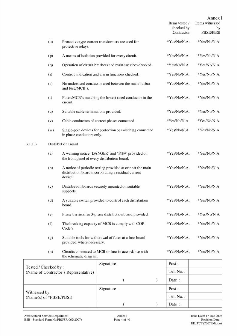
(o) Protective type current transformers are used for
protective relays.
*Yes/No/N.A. *Yes/No/N.A.
(p) A means of isolation provided for every circuit. *Yes/No/N.A. *Yes/No/N.A.
(q) Operation of circuit breakers and main switches checked. *Yes/No/N.A. *Yes/No/N.A.
(r) Control, indication and alarm functions checked. *Yes/No/N.A. *Yes/No/N.A.
(s) No undersized conductor used between the main busbar
and fuse/MCB’s.
*Yes/No/N.A. *Yes/No/N.A.
(t) Fuses/MCB’s matching the lowest rated conductor in the
circuit.
*Yes/No/N.A. *Yes/No/N.A.
(u) Suitable cable terminations provided. *Yes/No/N.A. *Yes/No/N.A.
(v) Cable conductors of correct phases connected. *Yes/No/N.A. *Yes/No/N.A.
(w) Single-pole devices for protection or switching connected
in phase conductors only.
*Yes/No/N.A. *Yes/No/N.A.
3.1.1.3 Distribution Board
(a) A warning notice ‘DANGER’ and ‘’ provided on
the front panel of every distribution board.
*Yes/No/N.A. *Yes/No/N.A.
(b) A notice of periodic testing provided at or near the main
distribution board incorporating a residual current
device.
*Yes/No/N.A. *Yes/No/N.A.
(c) Distribution boards securely mounted on suitable
supports.
*Yes/No/N.A. *Yes/No/N.A.
(d) A suitable switch provided to control each distribution
board.
*Yes/No/N.A. *Yes/No/N.A.
(e) Phase barriers for 3-phase distribution board provided. *Yes/No/N.A. *Yes/No/N.A.
(f) The breaking capacity of MCB is comply with COP
Code 9.
*Yes/No/N.A. *Yes/No/N.A.
(g) Suitable tools for withdrawal of fuses at a fuse board
provided, where necessary.
*Yes/No/N.A. *Yes/No/N.A.
(h) Circuits connected to MCB or fuse in accordance with
the schematic diagram.
*Yes/No/N.A. *Yes/No/N.A.

8/4/2019 e102 T&C Procedure of Electrical Installation in Gov Buildings (Hong Kong)
http://slidepdf.com/reader/full/e102-tc-procedure-of-electrical-installation-in-gov-buildings-hong-kong 34/100
Annex I
Signature - Post :
Tel. No. :Tested / Checked by :
(Name of Contractor’s Representative)
( ) Date :
Signature - Post :
Tel. No. :Witnessed by :(Name(s) of *PBSE/PBSI)
( ) Date :
Architectural Services Department Annex I Issue Date: 17 Dec 2007
BSB– Standard Form No:PBS/SR.062(2007) Page 5 of 40 Revision Date: -
EE_TCP (2007 Edition)
Items tested /
checked by
Contractor
Items witnessed
by
PBSE/PBSI
3.1.1.4 Conductors, Cables and wirings
(a) No visible damage to impair safety.
(b) All live conductors and their methods of insulation, in
relation to design currents of circuits and to the operating
currents of the protective devices, are properly selected
and erected.
*Yes/No/N.A. *Yes/No/N.A.
(c) All cables, flexible cords, switches, plugs and socket
outlets, accessories and equipment are found to be in
good working conditions.
*Yes/No/N.A. *Yes/No/N.A.
(d) All conductors are correctly and securely connected and
identified.
*Yes/No/N.A. *Yes/No/N.A.
(e) Armoured cables properly terminated to metal casing or
trunking by proper cable glands.
*Yes/No/N.A. *Yes/No/N.A.
(f) Cables passing through smoke lobby protected by
enclosures of adequate fire rating.
*Yes/No/N.A. *Yes/No/N.A.
(g) Non-sheathed cables protected by conduit, trunking or
ducting.
*Yes/No/N.A. *Yes/No/N.A.
(h) Cables and ductings adequately supported. *Yes/No/N.A. *Yes/No/N.A.
(i) Cables at distribution board or busbar terminated with
cable lugs.
*Yes/No/N.A. *Yes/No/N.A.
(j) Main cables connected up with correct polarity. *Yes/No/N.A. *Yes/No/N.A.
(k) Cables protected against mechanical damage and suitably
supported.
*Yes/No/N.A. *Yes/No/N.A.
(l) All exposed metal parts including the armour effectively
earthed.
*Yes/No/N.A. *Yes/No/N.A.

8/4/2019 e102 T&C Procedure of Electrical Installation in Gov Buildings (Hong Kong)
http://slidepdf.com/reader/full/e102-tc-procedure-of-electrical-installation-in-gov-buildings-hong-kong 35/100
Annex I
Signature - Post :
Tel. No. :Tested / Checked by :
(Name of Contractor’s Representative)
( ) Date :
Signature - Post :
Tel. No. :Witnessed by :(Name(s) of *PBSE/PBSI)
( ) Date :
Architectural Services Department Annex I Issue Date: 17 Dec 2007
BSB– Standard Form No:PBS/SR.062(2007) Page 6 of 40 Revision Date: -
EE_TCP (2007 Edition)
Items tested /
checked by
Contractor
Items witnessed
by
PBSE/PBSI
3.1.1.5 Busbar trunking system including rising mains
(a) The rising mains, lateral mains and meter boards
positioned at places accessible from public area.
*Yes/No/N.A. *Yes/No/N.A.
(b) Fire barriers provided where the busbar trunking system
passes through floor slabs or walls designated as fire
barriers.
*Yes/No/N.A. *Yes/No/N.A.
(c) Cables passing through smoke lobby protected by
enclosures of adequate fire rating.
*Yes/No/N.A. *Yes/No/N.A.
(d) Non-sheathed cables protected by conduit, trunking or
ducting.
*Yes/No/N.A. *Yes/No/N.A.
(e) Busbar trunking systems, cables and ductings adequatelysupported. *Yes/No/N.A. *Yes/No/N.A.
(f) The bolts, nuts, screws, etc. for busbar supports, busbar
connections have been checked for correct tightness in
accordance with manufacturers’ recommendations.
*Yes/No/N.A. *Yes/No/N.A.
(g) The busbar trunking system is properly and correctly
installed and aligned.
*Yes/No/N.A. *Yes/No/N.A.
(h) No dust, foreign particles and deleterious substances are
accumulated on the busbar trunking system.
*Yes/No/N.A. *Yes/No/N.A.
(i) The busbar trunking system is free from condensation. *Yes/No/N.A. *Yes/No/N.A.
(j) Armoured cables properly terminated to metal casing or
trunking by proper cable glands.
*Yes/No/N.A. *Yes/No/N.A.
(k) Suitable cable lugs used for terminating cables. *Yes/No/N.A. *Yes/No/N.A.
(l) Precaution against corrosion taking on aluminium
conductor joined to copper conductor.
*Yes/No/N.A. *Yes/No/N.A.
(m) Cutout fuses for tapping off supply fitted with insulated
carriers.
*Yes/No/N.A. *Yes/No/N.A.

8/4/2019 e102 T&C Procedure of Electrical Installation in Gov Buildings (Hong Kong)
http://slidepdf.com/reader/full/e102-tc-procedure-of-electrical-installation-in-gov-buildings-hong-kong 36/100
Annex I
Signature - Post :
Tel. No. :Tested / Checked by :
(Name of Contractor’s Representative)
( ) Date :
Signature - Post :
Tel. No. :Witnessed by :(Name(s) of *PBSE/PBSI)
( ) Date :
Architectural Services Department Annex I Issue Date: 17 Dec 2007
BSB– Standard Form No:PBS/SR.062(2007) Page 7 of 40 Revision Date: -
EE_TCP (2007 Edition)
Items tested /
checked by
Contractor
Items witnessed
by
PBSE/PBSI
3.1.1.6 Final Circuits
(a) All fuses and single pole switches connected to the phase
conductors only with correct polarity.
*Yes/No/N.A. *Yes/No/N.A.
(b) Wiring for emergency lightings and fire services
installation segregated from other wirings.
*Yes/No/N.A. *Yes/No/N.A.
(c) Low voltage circuits segregated from extra low voltage
circuits.
*Yes/No/N.A. *Yes/No/N.A.
(d) Cables of all phases and neutral of the circuit bunched
and contained in the same conduit.
*Yes/No/N.A. *Yes/No/N.A.
(e) Exposed insulated non-sheathed cables protected. *Yes/No/N.A. *Yes/No/N.A.
(f) Wiring inside false ceiling protected by conduit/trunking
or metallic sheath.
*Yes/No/N.A. *Yes/No/N.A.
(g) Socket outlets installed below 1.5m from floor being
shuttered type complying with the prescribed
requirements.
*Yes/No/N.A. *Yes/No/N.A.
(h) No socket outlet installed close to water tap, gas tap or
cooker so as to avoid danger.
*Yes/No/N.A. *Yes/No/N.A.
(i) Floor socket outlets protected with suitable cover. *Yes/No/N.A. *Yes/No/N.A.
(j) No 2-pin sockets installed. All socket outlets connectedwith protective conductors and live conductors
terminated at correct terminals.
*Yes/No/N.A. *Yes/No/N.A.
(k) Radial final circuits using 5A/15A socket outlets in
compliance with Code 6D.
*Yes/No/N.A. *Yes/No/N.A.
(l) Final circuits using 13A socket outlets in compliance
with Code 6E.
*Yes/No/N.A. *Yes/No/N.A.
(m) Final circuits using industrial socket outlets in
compliance with Code 6F or 6G or 6H.
*Yes/No/N.A. *Yes/No/N.A.
(n) Circuit protective conductor is formed by the enclosure
and a separate protective conductor between the earthing
terminal of socket outlet and its associated metal box
provided.
*Yes/No/N.A. *Yes/No/N.A.
8/4/2019 e102 T&C Procedure of Electrical Installation in Gov Buildings (Hong Kong)
http://slidepdf.com/reader/full/e102-tc-procedure-of-electrical-installation-in-gov-buildings-hong-kong 37/100
Annex I
Signature - Post :
Tel. No. :Tested / Checked by :
(Name of Contractor’s Representative)
( ) Date :
Signature - Post :
Tel. No. :Witnessed by :(Name(s) of *PBSE/PBSI)
( ) Date :
Architectural Services Department Annex I Issue Date: 17 Dec 2007
BSB– Standard Form No:PBS/SR.062(2007) Page 8 of 40 Revision Date: -
EE_TCP (2007 Edition)
Items tested /
checked by
Contractor
Items witnessed
by
PBSE/PBSI
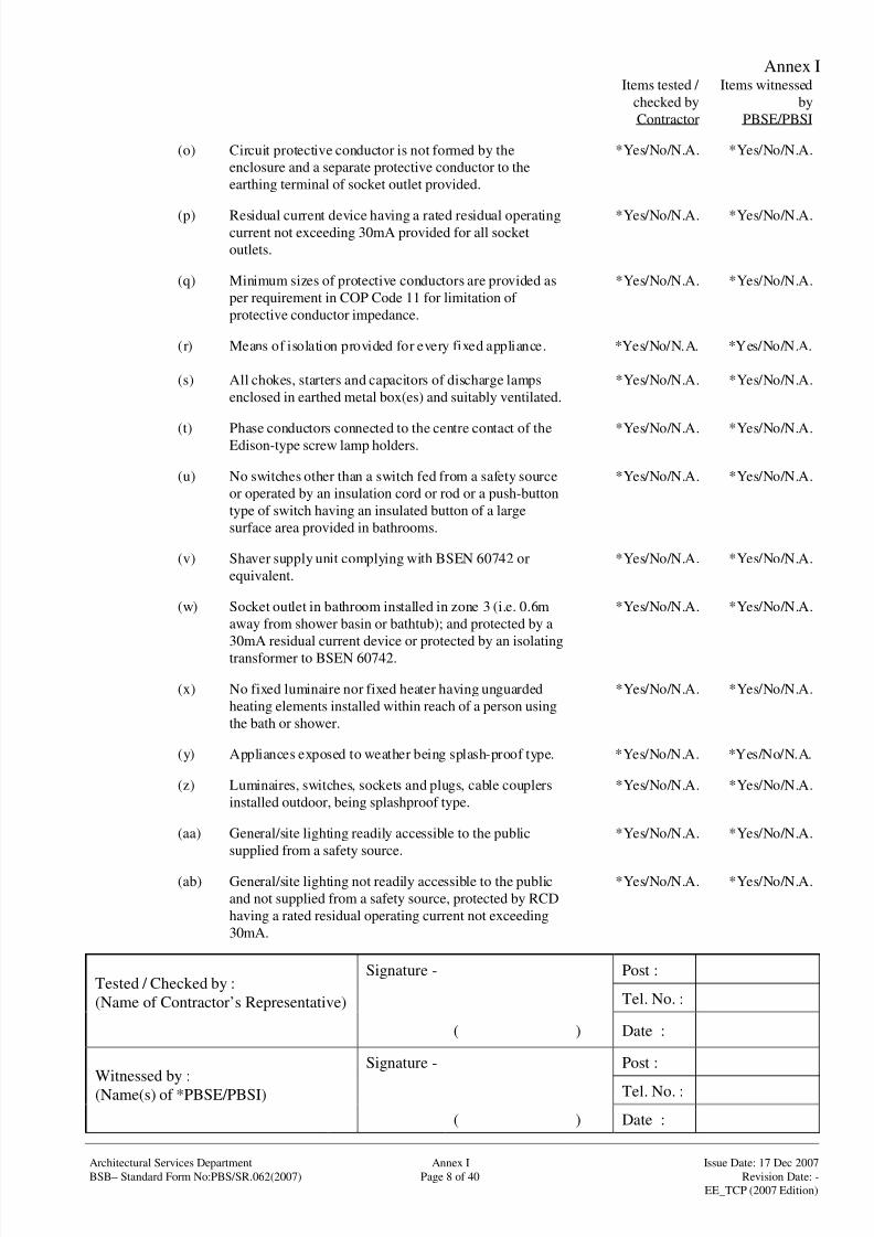
(o) Circuit protective conductor is not formed by the
enclosure and a separate protective conductor to the
earthing terminal of socket outlet provided.
*Yes/No/N.A. *Yes/No/N.A.
(p) Residual current device having a rated residual operatingcurrent not exceeding 30mA provided for all socket
outlets.
*Yes/No/N.A. *Yes/No/N.A.
(q) Minimum sizes of protective conductors are provided as
per requirement in COP Code 11 for limitation of
protective conductor impedance.
*Yes/No/N.A. *Yes/No/N.A.
(r) Means of isolation provided for every fixed appliance. *Yes/No/N.A. *Yes/No/N.A.
(s) All chokes, starters and capacitors of discharge lamps
enclosed in earthed metal box(es) and suitably ventilated.
*Yes/No/N.A. *Yes/No/N.A.
(t) Phase conductors connected to the centre contact of theEdison-type screw lamp holders. *Yes/No/N.A. *Yes/No/N.A.
(u) No switches other than a switch fed from a safety source
or operated by an insulation cord or rod or a push-button
type of switch having an insulated button of a large
surface area provided in bathrooms.
*Yes/No/N.A. *Yes/No/N.A.
(v) Shaver supply unit complying with BSEN 60742 or
equivalent.
*Yes/No/N.A. *Yes/No/N.A.
(w) Socket outlet in bathroom installed in zone 3 (i.e. 0.6m
away from shower basin or bathtub); and protected by a
30mA residual current device or protected by an isolating
transformer to BSEN 60742.
*Yes/No/N.A. *Yes/No/N.A.
(x) No fixed luminaire nor fixed heater having unguarded
heating elements installed within reach of a person using
the bath or shower.
*Yes/No/N.A. *Yes/No/N.A.
(y) Appliances exposed to weather being splash-proof type. *Yes/No/N.A. *Yes/No/N.A.
(z) Luminaires, switches, sockets and plugs, cable couplers
installed outdoor, being splashproof type.
*Yes/No/N.A. *Yes/No/N.A.
(aa) General/site lighting readily accessible to the public
supplied from a safety source.
*Yes/No/N.A. *Yes/No/N.A.
(ab) General/site lighting not readily accessible to the public
and not supplied from a safety source, protected by RCD
having a rated residual operating current not exceeding
30mA.
*Yes/No/N.A. *Yes/No/N.A.
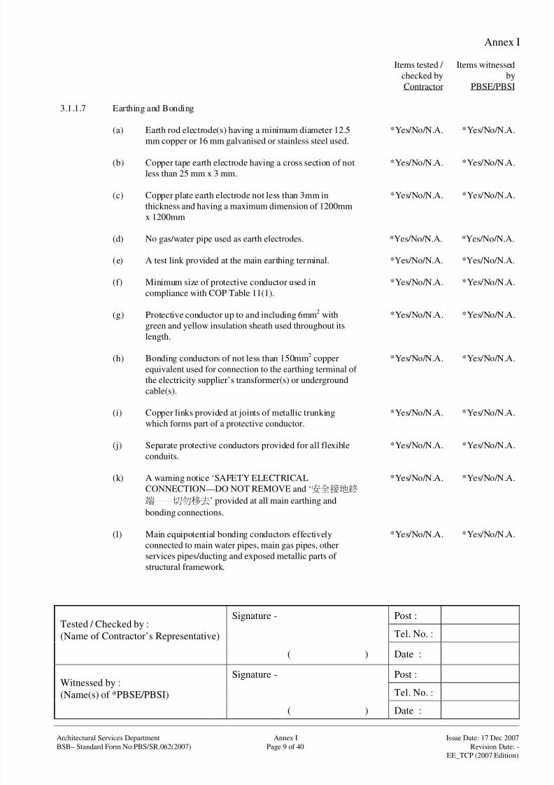
8/4/2019 e102 T&C Procedure of Electrical Installation in Gov Buildings (Hong Kong)
http://slidepdf.com/reader/full/e102-tc-procedure-of-electrical-installation-in-gov-buildings-hong-kong 38/100
Annex I
Signature - Post :
Tel. No. :Tested / Checked by :
(Name of Contractor’s Representative)
( ) Date :
Signature - Post :
Tel. No. :Witnessed by :(Name(s) of *PBSE/PBSI)
( ) Date :
Architectural Services Department Annex I Issue Date: 17 Dec 2007
BSB– Standard Form No:PBS/SR.062(2007) Page 9 of 40 Revision Date: -
EE_TCP (2007 Edition)
Items tested /
checked by
Contractor
Items witnessed
by
PBSE/PBSI
3.1.1.7 Earthing and Bonding
(a) Earth rod electrode(s) having a minimum diameter 12.5
mm copper or 16 mm galvanised or stainless steel used.
*Yes/No/N.A. *Yes/No/N.A.
(b) Copper tape earth electrode having a cross section of not
less than 25 mm x 3 mm.
*Yes/No/N.A. *Yes/No/N.A.
(c) Copper plate earth electrode not less than 3mm in
thickness and having a maximum dimension of 1200mm
x 1200mm
*Yes/No/N.A. *Yes/No/N.A.
(d) No gas/water pipe used as earth electrodes. *Yes/No/N.A. *Yes/No/N.A.
(e) A test link provided at the main earthing terminal. *Yes/No/N.A. *Yes/No/N.A.
(f) Minimum size of protective conductor used in
compliance with COP Table 11(1).
*Yes/No/N.A. *Yes/No/N.A.
(g) Protective conductor up to and including 6mm2 with
green and yellow insulation sheath used throughout its
length.
*Yes/No/N.A. *Yes/No/N.A.
(h) Bonding conductors of not less than 150mm2 copper
equivalent used for connection to the earthing terminal of
the electricity supplier’s transformer(s) or underground
cable(s).
*Yes/No/N.A. *Yes/No/N.A.
(i) Copper links provided at joints of metallic trunkingwhich forms part of a protective conductor.
*Yes/No/N.A. *Yes/No/N.A.
(j) Separate protective conductors provided for all flexible
conduits.
*Yes/No/N.A. *Yes/No/N.A.
(k) A warning notice ‘SAFETY ELECTRICAL
CONNECTION—DO NOT REMOVE and ‘
——’ provided at all main earthing and
bonding connections.
*Yes/No/N.A. *Yes/No/N.A.
(l) Main equipotential bonding conductors effectively
connected to main water pipes, main gas pipes, other
services pipes/ducting and exposed metallic parts of
structural framework.
*Yes/No/N.A. *Yes/No/N.A.

8/4/2019 e102 T&C Procedure of Electrical Installation in Gov Buildings (Hong Kong)
http://slidepdf.com/reader/full/e102-tc-procedure-of-electrical-installation-in-gov-buildings-hong-kong 39/100
Annex I
Signature - Post :
Tel. No. :Tested / Checked by :
(Name of Contractor’s Representative)
( ) Date :
Signature - Post :
Tel. No. :Witnessed by :(Name(s) of *PBSE/PBSI)
( ) Date :
Architectural Services Department Annex I Issue Date: 17 Dec 2007
BSB– Standard Form No:PBS/SR.062(2007) Page 10 of 40 Revision Date: -
EE_TCP (2007 Edition)
Items tested /
checked by
Contractor
Items witnessed
by
PBSE/PBSI
(m) Supplementary equipotential bonding effectively
provided between exposed conductive parts and
extraneous conductive parts.
*Yes/No/N.A. *Yes/No/N.A.
(n) Exposed conductive parts of fixed equipment installed
outside equipotential zone effectively earthed for 0.4 sec.
disconnection.
*Yes/No/N.A. *Yes/No/N.A.
(o) Exposed conductive parts of fixed equipment installed
within equipotential zone effectively earthed for 5 sec.
disconnection.
*Yes/No/N.A. *Yes/No/N.A.
(p) Effectiveness of the main equipotential bonding
connection to the main earthing terminal and lightning
protection system.
*Yes/No/N.A. *Yes/No/N.A.
(q) Earthing conductors of adequate size. *Yes/No/N.A. *Yes/No/N.A.
3.1.1.8 Lightning Protection
(a) The continuity of air termination network /down
conductor /earth termination network has been checked
and found satisfactory.
*Yes/No/N.A. *Yes/No/N.A.
(b) All conductors and joints for lightning protection system
are electrically and mechanically sound and correctly
connected.
*Yes/No/N.A. *Yes/No/N.A.
(c) Connection link to the main earthing terminal provided.Test joint provided
*Yes/No/N.A. *Yes/No/N.A.
(d) Rod electrode(s) having a minimum diameter 12.5 mm
copper or 16 mm galvanised or stainless steel used.
*Yes/No/N.A. *Yes/No/N.A.
(e) Copper tape electrode having a crosssection of not less
than 25 mm x 3 mm.
*Yes/No/N.A. *Yes/No/N.A.
(f) Copper plate electrode not less than 3 mm in thickness
and having a maximum dimension of 1200mm x
1200mm
*Yes/No/N.A. *Yes/No/N.A.
(g) No gas/water pipe used as earth electrodes. *Yes/No/N.A. *Yes/No/N.A.
(h) No evidence of corrosion likely to lead deterioration of
the lightning protection system.
*Yes/No/N.A. *Yes/No/N.A.

8/4/2019 e102 T&C Procedure of Electrical Installation in Gov Buildings (Hong Kong)
http://slidepdf.com/reader/full/e102-tc-procedure-of-electrical-installation-in-gov-buildings-hong-kong 40/100
Annex I
Signature - Post :
Tel. No. :Tested / Checked by :
(Name of Contractor’s Representative)
( ) Date :
Signature - Post :
Tel. No. :Witnessed by :(Name(s) of *PBSE/PBSI)
( ) Date :
Architectural Services Department Annex I Issue Date: 17 Dec 2007
BSB– Standard Form No:PBS/SR.062(2007) Page 11 of 40 Revision Date: -
EE_TCP (2007 Edition)
Items tested /
checked by
Contractor
Items witnessed
by
PBSE/PBSI
3.1.1.9 Motors /Transformers
(a) No visible damage to impair safety. *Yes/No/N.A. *Yes/No/N.A.
(b) A local switch was provided to control every motor *Yes/No/N.A. *Yes/No/N.A.
(c) Means provided to prevent unexpected restarting of
motors where such restarting might cause danger.
*Yes/No/N.A. *Yes/No/N.A.
(d) Flexible conduits terminated with suitable brass bushes. *Yes/No/N.A. *Yes/No/N.A.
(e) Separate supply to motor heaters having its terminals
screened, with warning notice provided.
*Yes/No/N.A. *Yes/No/N.A.
(f) All accessible live parts screened with insulating plate orearthed metal. *Yes/No/N.A. *Yes/No/N.A.
(g) Proper ventilation provided to avoid excessive
temperature rise.
*Yes/No/N.A. *Yes/No/N.A.
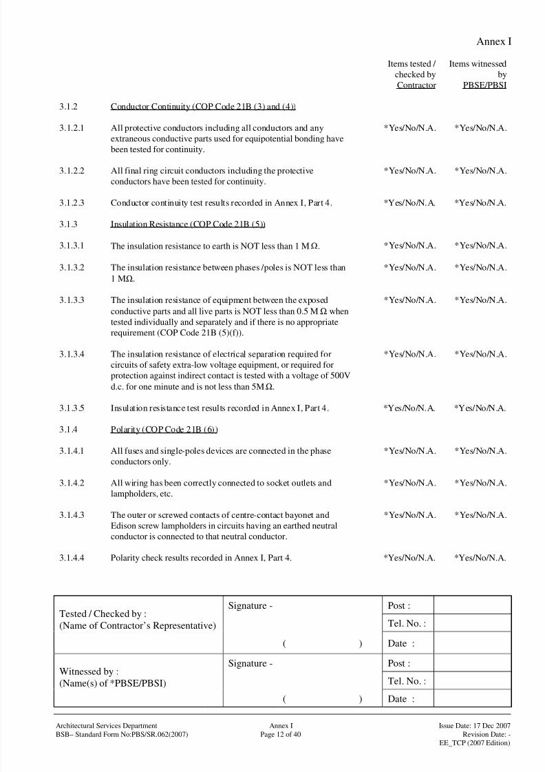
8/4/2019 e102 T&C Procedure of Electrical Installation in Gov Buildings (Hong Kong)
http://slidepdf.com/reader/full/e102-tc-procedure-of-electrical-installation-in-gov-buildings-hong-kong 41/100
Annex I
Signature - Post :
Tel. No. :Tested / Checked by :
(Name of Contractor’s Representative)
( ) Date :
Signature - Post :
Tel. No. :Witnessed by :(Name(s) of *PBSE/PBSI)
( ) Date :
Architectural Services Department Annex I Issue Date: 17 Dec 2007
BSB– Standard Form No:PBS/SR.062(2007) Page 12 of 40 Revision Date: -
EE_TCP (2007 Edition)
Items tested /
checked by
Contractor
Items witnessed
by
PBSE/PBSI
3.1.2 Conductor Continuity (COP Code 21B (3) and (4))
3.1.2.1 All protective conductors including all conductors and any
extraneous conductive parts used for equipotential bonding have
been tested for continuity.
*Yes/No/N.A. *Yes/No/N.A.
3.1.2.2 All final ring circuit conductors including the protective
conductors have been tested for continuity.
*Yes/No/N.A. *Yes/No/N.A.
3.1.2.3 Conductor continuity test results recorded in Annex I, Part 4. *Yes/No/N.A. *Yes/No/N.A.
3.1.3 Insulation Resistance (COP Code 21B (5))
3.1.3.1 The insulation resistance to earth is NOT less than 1 MΩ. *Yes/No/N.A. *Yes/No/N.A.
3.1.3.2 The insulation resistance between phases /poles is NOT less than1 MΩ.
*Yes/No/N.A. *Yes/No/N.A.
3.1.3.3 The insulation resistance of equipment between the exposed
conductive parts and all live parts is NOT less than 0.5 MΩ when
tested individually and separately and if there is no appropriate
requirement (COP Code 21B (5)(f)).
*Yes/No/N.A. *Yes/No/N.A.
3.1.3.4 The insulation resistance of electrical separation required for
circuits of safety extra-low voltage equipment, or required for
protection against indirect contact is tested with a voltage of 500V
d.c. for one minute and is not less than 5MΩ.
*Yes/No/N.A. *Yes/No/N.A.
3.1.3.5 Insulation resistance test results recorded in Annex I, Part 4. *Yes/No/N.A. *Yes/No/N.A.
3.1.4 Polarity (COP Code 21B (6))
3.1.4.1 All fuses and single-poles devices are connected in the phase
conductors only.
*Yes/No/N.A. *Yes/No/N.A.
3.1.4.2 All wiring has been correctly connected to socket outlets and
lampholders, etc.
*Yes/No/N.A. *Yes/No/N.A.
3.1.4.3 The outer or screwed contacts of centre-contact bayonet and
Edison screw lampholders in circuits having an earthed neutral
conductor is connected to that neutral conductor.
*Yes/No/N.A. *Yes/No/N.A.
3.1.4.4 Polarity check results recorded in Annex I, Part 4. *Yes/No/N.A. *Yes/No/N.A.

8/4/2019 e102 T&C Procedure of Electrical Installation in Gov Buildings (Hong Kong)
http://slidepdf.com/reader/full/e102-tc-procedure-of-electrical-installation-in-gov-buildings-hong-kong 42/100
Annex I
Signature - Post :
Tel. No. :Tested / Checked by :
(Name of Contractor’s Representative)
( ) Date :
Signature - Post :
Tel. No. :Witnessed by :(Name(s) of *PBSE/PBSI)
( ) Date :
Architectural Services Department Annex I Issue Date: 17 Dec 2007
BSB– Standard Form No:PBS/SR.062(2007) Page 13 of 40 Revision Date: -
EE_TCP (2007 Edition)
Items tested /
checked by
Contractor
Items witnessed
by
PBSE/PBSI
3.1.5 Earth Electrode Resistance (COP Code 21B (7))
3.1.5.1 The resistance to earth has been measured at the position of every
earth electrode and of the main earth terminal. The results are
satisfactory.
*Yes/No/N.A. *Yes/No/N.A.
3.1.5.2 Details of earth electrode and resistance test results recorded in
Annex I, Part 4.
*Yes/No/N.A. *Yes/No/N.A.
3.1.6 Earth Fault Loop Impedance (COP Code 21B (8))
3.1.6.1 The earth fault loop impedance of all circuits has been found
satisfactory for operation of the protective devices for earth fault
protection.
*Yes/No/N.A. *Yes/No/N.A.
3.1.6.2 Earth fault loop impedance measurement results recorded on
Annex I, Part 4.
*Yes/No/N.A. *Yes/No/N.A.
3.1.7 Functional Testing of All Devices Including Protective Devices
(COP Code 21B (9))
3.1.7.1 Simulation tests on the operation of devices for earth fault
protection are satisfactory.
*Yes/No/N.A. *Yes/No/N.A.
3.1.7.2 50% of the rated tripping current shall not cause the residual
current circuit breaker to open.
*Yes/No/N.A. *Yes/No/N.A.
3.1.7.3 100% of the rated tripping current shall cause the residual current
circuit breaker to open within 300ms or at any delay time declared
by the manufacturer of the device.
*Yes/No/N.A. *Yes/No/N.A.
3.1.7.4 Where the residual current circuit breaker has a rated tripping
current not exceeding 30mA and has been installed to reduce the
risk associated with direct contact, a residual current of 150mA
should cause the circuit breaker to open within 40ms.
*Yes/No/N.A. *Yes/No/N.A.
3.1.7.5 In no event should the test current be applied for a period
exceeding one second.
*Yes/No/N.A. *Yes/No/N.A.
3.1.7.6 Hand operation on protective devices such as miniature circuit
breakers, moulded case circuit breakers, air circuit breakers, fused
switches, switch-fuses and protective relays, etc. are satisfactory.
*Yes/No/N.A. *Yes/No/N.A.
3.1.7.7 Hand operation on all items of equipment such as isolators,
switches and indicative devices are satisfactory.
*Yes/No/N.A. *Yes/No/N.A.
3.1.7.8 Functional test of all devices including protective devices had
been recorded on Annex I, Part 4.
*Yes/No/N.A. *Yes/No/N.A.

8/4/2019 e102 T&C Procedure of Electrical Installation in Gov Buildings (Hong Kong)
http://slidepdf.com/reader/full/e102-tc-procedure-of-electrical-installation-in-gov-buildings-hong-kong 43/100
Annex I
Signature - Post :
Tel. No. :Tested / Checked by :
(Name of Contractor’s Representative)
( ) Date :
Signature - Post :
Tel. No. :Witnessed by :(Name(s) of *PBSE/PBSI)
( ) Date :
Architectural Services Department Annex I Issue Date: 17 Dec 2007
BSB– Standard Form No:PBS/SR.062(2007) Page 14 of 40 Revision Date: -
EE_TCP (2007 Edition)
Items tested /
checked by
Contractor
Items witnessed
by
PBSE/PBSI
3.1.8 Additional Checks for Installations in Hazardous Environment
(COP Code 21B (10))
3.1.8.1 The equipment is suitably protected according to the types of
protection under COP Code 15. The integrity of the protection
provided for the equipment is not jeopardised by the method of
installation. No alteration that may invalidate the conditions of
protection has been used.
*Yes/No/N.A. *Yes/No/N.A.
3.1.8.2 No dust, foreign particles and deleterious substances are
accumulated on the equipment. The equipment is free from
condensation.
*Yes/No/N.A. *Yes/No/N.A.
3.1.8.3 Lamps, fuses and replaceable parts of correct rating and types are
used.
*Yes/No/N.A. *Yes/No/N.A.
3.1.8.4 The surface temperature of all equipment is appropriate to the
type of protection provided.
*Yes/No/N.A. *Yes/No/N.A.
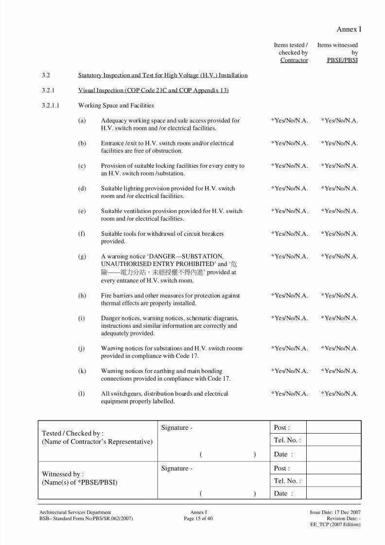
8/4/2019 e102 T&C Procedure of Electrical Installation in Gov Buildings (Hong Kong)
http://slidepdf.com/reader/full/e102-tc-procedure-of-electrical-installation-in-gov-buildings-hong-kong 44/100
Annex I
Signature - Post :
Tel. No. :Tested / Checked by :
(Name of Contractor’s Representative)
( ) Date :
Signature - Post :
Tel. No. :Witnessed by :(Name(s) of *PBSE/PBSI)
( ) Date :
Architectural Services Department Annex I Issue Date: 17 Dec 2007
BSB– Standard Form No:PBS/SR.062(2007) Page 15 of 40 Revision Date: -
EE_TCP (2007 Edition)
Items tested /
checked by
Contractor
Items witnessed
by
PBSE/PBSI
3.2 Statutory Inspection and Test for High Voltage (H.V.) Installation
3.2.1 Visual Inspection (COP Code 21C and COP Appendix 13)
3.2.1.1 Working Space and Facilities
(a) Adequacy working space and safe access provided for
H.V. switch room and /or electrical facilities.
*Yes/No/N.A. *Yes/No/N.A.
(b) Entrance /exit to H.V. switch room and/or electrical
facilities are free of obstruction.
*Yes/No/N.A. *Yes/No/N.A.
(c) Provision of suitable locking facilities for every entry to
an H.V. switch room /substation.
*Yes/No/N.A. *Yes/No/N.A.
(d) Suitable lighting provision provided for H.V. switchroom and /or electrical facilities. *Yes/No/N.A. *Yes/No/N.A.
(e) Suitable ventilation provision provided for H.V. switch
room and /or electrical facilities.
*Yes/No/N.A. *Yes/No/N.A.
(f) Suitable tools for withdrawal of circuit breakers
provided.
*Yes/No/N.A. *Yes/No/N.A.
(g) A warning notice ‘DANGER—SUBSTATION,
UNAUTHORISED ENTRY PROHIBITED’ and ‘
——’ provided at
every entrance of H.V. switch room.
*Yes/No/N.A. *Yes/No/N.A.
(h) Fire barriers and other measures for protection against
thermal effects are properly installed.
*Yes/No/N.A. *Yes/No/N.A.
(i) Danger notices, warning notices, schematic diagrams,
instructions and similar information are correctly and
adequately provided.
*Yes/No/N.A. *Yes/No/N.A.
(j) Warning notices for substations and H.V. switch rooms
provided in compliance with Code 17.
*Yes/No/N.A. *Yes/No/N.A.
(k) Warning notices for earthing and main bonding
connections provided in compliance with Code 17.
*Yes/No/N.A. *Yes/No/N.A.
(l) All switchgears, distribution boards and electrical
equipment properly labelled.
*Yes/No/N.A. *Yes/No/N.A.

8/4/2019 e102 T&C Procedure of Electrical Installation in Gov Buildings (Hong Kong)
http://slidepdf.com/reader/full/e102-tc-procedure-of-electrical-installation-in-gov-buildings-hong-kong 45/100
Annex I
Signature - Post :
Tel. No. :Tested / Checked by :
(Name of Contractor’s Representative)
( ) Date :
Signature - Post :
Tel. No. :Witnessed by :(Name(s) of *PBSE/PBSI)
( ) Date :
Architectural Services Department Annex I Issue Date: 17 Dec 2007
BSB– Standard Form No:PBS/SR.062(2007) Page 16 of 40 Revision Date: -
EE_TCP (2007 Edition)
Items tested /
checked by
Contractor
Items witnessed
by
PBSE/PBSI
(m) Continuity of protective conductors especially the
bonding of all exposed conductive parts are satisfactory.
*Yes/No/N.A. *Yes/No/N.A.
(n) Provision of padlock facilities for shutters, key boxes etc.
provided.
*Yes/No/N.A. *Yes/No/N.A.
(o) Logbook provided and work done properly recorded. *Yes/No/N.A. *Yes/No/N.A.
(p) Other inspection items as required by the manufacturers
of related equipment are satisfactory.
*Yes/No/N.A. *Yes/No/N.A.
3.2.1.2 Switchboard and Circuit Breakers
(a) No visible damage to impair safety. *Yes/No/N.A. *Yes/No/N.A.
(b) Appropriate devices provided for isolation and switching. *Yes/No/N.A. *Yes/No/N.A.
(c) Every circuit breaker provided with a legible and durable
identification label.
*Yes/No/N.A. *Yes/No/N.A.
(d) An up-to-date schematic diagram displayed. *Yes/No/N.A. *Yes/No/N.A.
(e) All accessible live parts screened with insulating plate or
earthed metal.
*Yes/No/N.A. *Yes/No/N.A.
(f) All exposed conductive parts effectively earthed. *Yes/No/N.A. *Yes/No/N.A.
(g) Earthing system effectively connected. *Yes/No/N.A. *Yes/No/N.A.
(h) Warning notice displayed at main bonding connections. *Yes/No/N.A. *Yes/No/N.A.
(i) All protective devices are functioned properly and
correctly set.
*Yes/No/N.A. *Yes/No/N.A.
(j) Initial /maintenance test carried out according to relevant
recognised standards and manufacturers’
recommendation, where appropriate, with test reports.
(insulation resistance test, pressure test etc.)
*Yes/No/N.A. *Yes/No/N.A.
(k) Other inspection items as required by the manufacturers
of related equipment are satisfactory.
*Yes/No/N.A. *Yes/No/N.A.

8/4/2019 e102 T&C Procedure of Electrical Installation in Gov Buildings (Hong Kong)
http://slidepdf.com/reader/full/e102-tc-procedure-of-electrical-installation-in-gov-buildings-hong-kong 46/100
Annex I
Signature - Post :
Tel. No. :Tested / Checked by :
(Name of Contractor’s Representative)
( ) Date :
Signature - Post :
Tel. No. :Witnessed by :(Name(s) of *PBSE/PBSI)
( ) Date :
Architectural Services Department Annex I Issue Date: 17 Dec 2007
BSB– Standard Form No:PBS/SR.062(2007) Page 17 of 40 Revision Date: -
EE_TCP (2007 Edition)
Items tested /
checked by
Contractor
Items witnessed
by
PBSE/PBSI
3.2.1.3 Conductors, Cables and wirings
(a) No visible damage to impair safety. *Yes/No/N.A. *Yes/No/N.A.
(b) All live conductors and their methods of insulation, in
relation to design currents of circuits and to the operating
currents of the protective devices, are properly selected
and erected.
*Yes/No/N.A. *Yes/No/N.A.
(c) All cables, flexible cords, switches, plugs and socket
outlets, accessories and equipment are found to be in
good working conditions.
*Yes/No/N.A. *Yes/No/N.A.
(d) All conductors are correctly and securely connected and
identified.
*Yes/No/N.A. *Yes/No/N.A.
(e) Armoured cables properly terminated to metal casing or
trunking by proper cable glands.
*Yes/No/N.A. *Yes/No/N.A.
(f) Cables passing through smoke lobby protected by
enclosures of adequate fire rating.
*Yes/No/N.A. *Yes/No/N.A.
(g) Non-sheathed cables protected by conduit, trunking or
ducting.
*Yes/No/N.A. *Yes/No/N.A.
(h) Cables and ductings adequately supported. *Yes/No/N.A. *Yes/No/N.A.
(i) Cables at distribution board or busbar terminated with
cable lugs.
*Yes/No/N.A. *Yes/No/N.A.
(j) Main cables connected up with correct polarity. *Yes/No/N.A. *Yes/No/N.A.
(k) Cables protected against mechanical damage and suitably
supported.
*Yes/No/N.A. *Yes/No/N.A.
(l) All exposed metal parts including the armour effectively
earthed.
*Yes/No/N.A. *Yes/No/N.A.
(m) Initial /maintenance test carried out according to relevant
recognised standards and manufacturers’
recommendation, where appropriate, with test reports.
(insulation resistance test, pressure test etc.)
*Yes/No/N.A. *Yes/No/N.A.
(n) Other inspection items as required by the manufacturers
of related equipment are satisfactory.
*Yes/No/N.A. *Yes/No/N.A.

8/4/2019 e102 T&C Procedure of Electrical Installation in Gov Buildings (Hong Kong)
http://slidepdf.com/reader/full/e102-tc-procedure-of-electrical-installation-in-gov-buildings-hong-kong 47/100
Annex I
Signature - Post :
Tel. No. :Tested / Checked by :
(Name of Contractor’s Representative)
( ) Date :
Signature - Post :
Tel. No. :Witnessed by :(Name(s) of *PBSE/PBSI)
( ) Date :
Architectural Services Department Annex I Issue Date: 17 Dec 2007
BSB– Standard Form No:PBS/SR.062(2007) Page 18 of 40 Revision Date: -
EE_TCP (2007 Edition)
Items tested /
checked by
Contractor
Items witnessed
by
PBSE/PBSI
3.2.1.4 Transformers /Motors
(a) No visible damage to impair safety. *Yes/No/N.A. *Yes/No/N.A.
(b) All accessible live parts screened with insulating plate or
earthed metal.
*Yes/No/N.A. *Yes/No/N.A.
(c) Proper ventilation provided to avoid excessive
temperature rise.
*Yes/No/N.A. *Yes/No/N.A.
(d) Initial /maintenance test carried out according to relevant
recognised standards and manufacturers’
recommendation, where appropriate, with test reports.
(insulation resistance test, pressure test etc.)
*Yes/No/N.A. *Yes/No/N.A.
(e) Other inspection items as required by the manufacturersof related equipment are satisfactory. *Yes/No/N.A. *Yes/No/N.A.
3.2.1.5 Earth
(a) A warning notice ‘SAFETY ELECTRICAL
CONNECTION—DO NOT REMOVE and ‘
——’ provided at all main earthing and
bonding connections.
*Yes/No/N.A. *Yes/No/N.A.
(b) Earthing conductors of adequate size. *Yes/No/N.A. *Yes/No/N.A.
(c) Other inspection items as required by the manufacturers
of related equipment are satisfactory.
*Yes/No/N.A. *Yes/No/N.A.
3.2.1.6 Direct Current (d.c.) Battery System
(a) Condition of battery system is satisfactory. *Yes/No/N.A. *Yes/No/N.A.
(b) Voltage of each battery cell measured. *Yes/No/N.A. *Yes/No/N.A.
(c) Other inspection items as required by the manufacturers
of related equipment are satisfactory.
*Yes/No/N.A. *Yes/No/N.A.
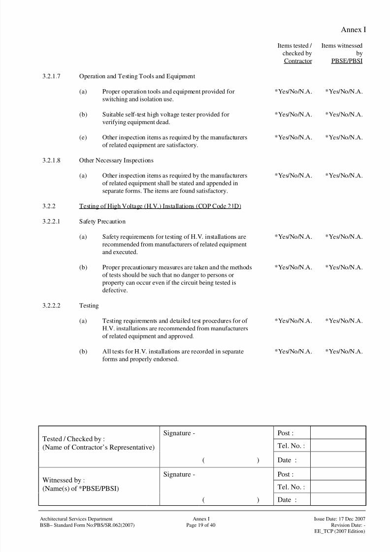
8/4/2019 e102 T&C Procedure of Electrical Installation in Gov Buildings (Hong Kong)
http://slidepdf.com/reader/full/e102-tc-procedure-of-electrical-installation-in-gov-buildings-hong-kong 48/100
Annex I
Signature - Post :
Tel. No. :Tested / Checked by :
(Name of Contractor’s Representative)
( ) Date :
Signature - Post :
Tel. No. :Witnessed by :(Name(s) of *PBSE/PBSI)
( ) Date :
Architectural Services Department Annex I Issue Date: 17 Dec 2007
BSB– Standard Form No:PBS/SR.062(2007) Page 19 of 40 Revision Date: -
EE_TCP (2007 Edition)
Items tested /
checked by
Contractor
Items witnessed
by
PBSE/PBSI
3.2.1.7 Operation and Testing Tools and Equipment
(a) Proper operation tools and equipment provided for
switching and isolation use.
*Yes/No/N.A. *Yes/No/N.A.
(b) Suitable self-test high voltage tester provided for
verifying equipment dead.
*Yes/No/N.A. *Yes/No/N.A.
(e) Other inspection items as required by the manufacturers
of related equipment are satisfactory.
*Yes/No/N.A. *Yes/No/N.A.
3.2.1.8 Other Necessary Inspections
(a) Other inspection items as required by the manufacturers
of related equipment shall be stated and appended in
separate forms. The items are found satisfactory.
*Yes/No/N.A. *Yes/No/N.A.
3.2.2 Testing of High Voltage (H.V.) Installations (COP Code 21D)
3.2.2.1 Safety Precaution
(a) Safety requirements for testing of H.V. installations are
recommended from manufacturers of related equipment
and executed.
*Yes/No/N.A. *Yes/No/N.A.
(b) Proper precautionary measures are taken and the methods
of tests should be such that no danger to persons or
property can occur even if the circuit being tested is
defective.
*Yes/No/N.A. *Yes/No/N.A.
3.2.2.2 Testing
(a) Testing requirements and detailed test procedures for of
H.V. installations are recommended from manufacturers
of related equipment and approved.
*Yes/No/N.A. *Yes/No/N.A.
(b) All tests for H.V. installations are recorded in separate
forms and properly endorsed.
*Yes/No/N.A. *Yes/No/N.A.
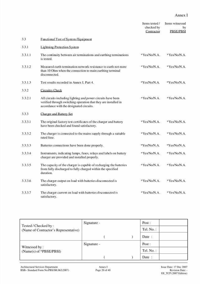
8/4/2019 e102 T&C Procedure of Electrical Installation in Gov Buildings (Hong Kong)
http://slidepdf.com/reader/full/e102-tc-procedure-of-electrical-installation-in-gov-buildings-hong-kong 49/100
Annex I
Signature - Post :
Tel. No. :Tested / Checked by :
(Name of Contractor’s Representative)
( ) Date :
Signature - Post :
Tel. No. :Witnessed by :(Name(s) of *PBSE/PBSI)
( ) Date :
Architectural Services Department Annex I Issue Date: 17 Dec 2007
BSB– Standard Form No:PBS/SR.062(2007) Page 20 of 40 Revision Date: -
EE_TCP (2007 Edition)
Items tested /
checked by
Contractor
Items witnessed
by
PBSE/PBSI
3.3 Functional Test of System /Equipment
3.3.1 Lightning Protection System
3.3.1.1 The continuity between air terminations and earthing terminations
is tested.
*Yes/No/N.A. *Yes/No/N.A.
3.3.1.2 Measured earth termination network resistance to earth not more
than 10 Ohm when the connection to main earthing terminal
disconnected.
*Yes/No/N.A. *Yes/No/N.A.
3.3.1.3 Test results recorded in Annex I, Part 4. *Yes/No/N.A. *Yes/No/N.A.
3.3.2 Circuitry Check
3.3.2.1 All circuits including lighting and power circuits have beenverified through switching operation that they are installed in
accordance with the designated circuits.
*Yes/No/N.A. *Yes/No/N.A.
3.3.3 Charger and Battery Set
3.3.3.1 The original factory test certificates of the charger and battery
have been checked and found satisfactory.
*Yes/No/N.A. *Yes/No/N.A.
3.3.3.2 The charger is connected to the mains supply through a suitable
rated fuse.
*Yes/No/N.A. *Yes/No/N.A.
3.3.3.3 Batteries connections have been done properly. *Yes/No/N.A. *Yes/No/N.A.
3.3.3.4 Instruments, indicating lamps, fuses, relays and labels on battery
charger are provided and installed properly.
*Yes/No/N.A. *Yes/No/N.A.
3.3.3.5 The capacity of the charger is capable of recharging the batteries
from fully discharged to fully charged within the specified
duration.
*Yes/No/N.A. *Yes/No/N.A.
3.3.3.6 The charger output on load with batteries disconnected is
satisfactory.
*Yes/No/N.A. *Yes/No/N.A.
3.3.3.7 The charger current on load with batteries disconnected is
satisfactory.
*Yes/No/N.A. *Yes/No/N.A.
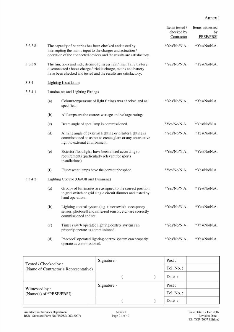
8/4/2019 e102 T&C Procedure of Electrical Installation in Gov Buildings (Hong Kong)
http://slidepdf.com/reader/full/e102-tc-procedure-of-electrical-installation-in-gov-buildings-hong-kong 50/100
Annex I
Signature - Post :
Tel. No. :Tested / Checked by :
(Name of Contractor’s Representative)
( ) Date :
Signature - Post :
Tel. No. :Witnessed by :(Name(s) of *PBSE/PBSI)
( ) Date :
Architectural Services Department Annex I Issue Date: 17 Dec 2007
BSB– Standard Form No:PBS/SR.062(2007) Page 21 of 40 Revision Date: -
EE_TCP (2007 Edition)
Items tested /
checked by
Contractor
Items witnessed
by
PBSE/PBSI
3.3.3.8 The capacity of batteries has been checked and tested by
interrupting the mains input to the charger and actuation /
operation of the connected devices and the results are satisfactory.
*Yes/No/N.A. *Yes/No/N.A.
3.3.3.9 The functions and indications of charger fail / main fail / battery
disconnected / boost charge / trickle charge, mains and battery
have been checked and tested and the results are satisfactory.
*Yes/No/N.A. *Yes/No/N.A.
3.3.4 Lighting Installation
3.3.4.1 Luminaires and Lighting Fittings
(a) Colour temperature of light fittings was checked and as
specified.
*Yes/No/N.A. *Yes/No/N.A.
(b) All lamps are the correct wattage and voltage ratings
(c) Beam angle of spot lamp is commissioned. *Yes/No/N.A. *Yes/No/N.A.
(d) Aiming angle of external lighting or planter lighting is
commissioned so as not to create glare or any obstructive
light to external environment.
*Yes/No/N.A. *Yes/No/N.A.
(e) Exterior floodlights have been aimed according to
requirements (particularly relevant for sports
installations)
*Yes/No/N.A. *Yes/No/N.A.
(f) Fluorescent lamps have the correct phosphor. *Yes/No/N.A. *Yes/No/N.A.
3.3.4.2 Lighting Control (On/Off and Dimming)
(a) Groups of luminaries are assigned to the correct position
in grid switch or grid single circuit dimmer and tested by
hand operation.
*Yes/No/N.A. *Yes/No/N.A.
(b) Lighting control system (e.g. timer switch, occupancy
sensor, photocell and infra-red sensor, etc.) are correctly
commissioned and set.
*Yes/No/N.A. *Yes/No/N.A.
(c) Timer switch operated lighting control system can
properly operate as commissioned.
*Yes/No/N.A. *Yes/No/N.A.
(d) Photocell operated lighting control system can properly
operate as commissioned.
*Yes/No/N.A. *Yes/No/N.A.

8/4/2019 e102 T&C Procedure of Electrical Installation in Gov Buildings (Hong Kong)
http://slidepdf.com/reader/full/e102-tc-procedure-of-electrical-installation-in-gov-buildings-hong-kong 51/100
Annex I
Signature - Post :
Tel. No. :Tested / Checked by :
(Name of Contractor’s Representative)
( ) Date :
Signature - Post :
Tel. No. :Witnessed by :(Name(s) of *PBSE/PBSI)
( ) Date :
Architectural Services Department Annex I Issue Date: 17 Dec 2007
BSB– Standard Form No:PBS/SR.062(2007) Page 22 of 40 Revision Date: -
EE_TCP (2007 Edition)
Items tested /
checked by
Contractor
Items witnessed
by
PBSE/PBSI
(e) Infra-red sensor operated lighting control system can
properly operate as commissioned.
*Yes/No/N.A. *Yes/No/N.A.
(f) Occupancy sensor operated lighting control system can
properly operate as commissioned.
*Yes/No/N.A. *Yes/No/N.A.
(g) FM radio switches have been configured to the relevant
receivers
*Yes/No/N.A. *Yes/No/N.A.
(h) Lighting control by CCMS or BMS is tested and properly
functioned.
*Yes/No/N.A. *Yes/No/N.A.
3.3.4.3 Lighting Measurement
(a) Illuminance level of lighting installation for individual
areas /rooms is measured under its design condition.
*Yes/No/N.A. *Yes/No/N.A.
(b) Measurement results recorded. *Yes/No/N.A. *Yes/No/N.A.
3.3.5 Digital Multifunction Power Meter
3.3.5.1 Manufacturer’s calibration certificate for each meter is provided. *Yes/No/N.A. *Yes/No/N.A.
3.3.5.2 The readings of electrical parameters by the meter and by test kit
are recorded in Annex I, Part 4.
*Yes/No/N.A. *Yes/No/N.A.
3.3.5.3 Remote monitoring functions by CCMS or BMS are tested and
found satisfactory.
*Yes/No/N.A. *Yes/No/N.A.
3.3.5.4 Interfacing functions for self-contained meter are tested by using
plug-in communication module and found satisfactory.
*Yes/No/N.A. *Yes/No/N.A.
3.3.5.5 Replacement mechanism of meter is tested and found satisfactory. *Yes/No/N.A. *Yes/No/N.A.
3.3.5.6 Current transformer (C.T.) shorting block to prevent open
circuiting the C.T. is provided and tested.
*Yes/No/N.A. *Yes/No/N.A.
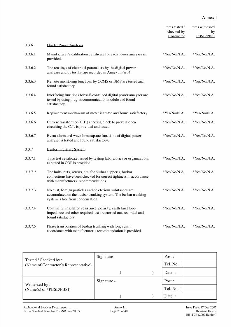
8/4/2019 e102 T&C Procedure of Electrical Installation in Gov Buildings (Hong Kong)
http://slidepdf.com/reader/full/e102-tc-procedure-of-electrical-installation-in-gov-buildings-hong-kong 52/100
Annex I
Signature - Post :
Tel. No. :Tested / Checked by :
(Name of Contractor’s Representative)
( ) Date :
Signature - Post :
Tel. No. :Witnessed by :(Name(s) of *PBSE/PBSI)
( ) Date :
Architectural Services Department Annex I Issue Date: 17 Dec 2007
BSB– Standard Form No:PBS/SR.062(2007) Page 23 of 40 Revision Date: -
EE_TCP (2007 Edition)
Items tested /
checked by
Contractor
Items witnessed
by
PBSE/PBSI
3.3.6 Digital Power Analyzer
3.3.6.1 Manufacturer’s calibration certificate for each power analyzer is
provided.
*Yes/No/N.A. *Yes/No/N.A.
3.3.6.2 The readings of electrical parameters by the digital power
analyzer and by test kit are recorded in Annex I, Part 4.
*Yes/No/N.A. *Yes/No/N.A.
3.3.6.3 Remote monitoring functions by CCMS or BMS are tested and
found satisfactory.
*Yes/No/N.A. *Yes/No/N.A.
3.3.6.4 Interfacing functions for self-contained digital power analyzer are
tested by using plug-in communication module and found
satisfactory.
*Yes/No/N.A. *Yes/No/N.A.
3.3.6.5 Replacement mechanism of meter is tested and found satisfactory. *Yes/No/N.A. *Yes/No/N.A.
3.3.6.6 Current transformer (C.T.) shorting block to prevent open
circuiting the C.T. is provided and tested.
*Yes/No/N.A. *Yes/No/N.A.
3.3.6.7 Event alarm and waveform capture functions of digital power
analyser is tested and found satisfactory.
*Yes/No/N.A. *Yes/No/N.A.
3.3.7 Busbar Trunking System
3.3.7.1 Type test certificate issued by testing laboratories or organizations
as stated in COP is provided.
*Yes/No/N.A. *Yes/No/N.A.
3.3.7.2 The bolts, nuts, screws, etc. for busbar supports, busbarconnections have been checked for correct tightness in accordance
with manufacturers’ recommendations.
*Yes/No/N.A. *Yes/No/N.A.
3.3.7.3 No dust, foreign particles and deleterious substances are
accumulated on the busbar trunking system. The busbar trunking
system is free from condensation.
*Yes/No/N.A. *Yes/No/N.A.
3.3.7.4 Continuity, insulation resistance, polarity, earth fault loop
impedance and other required test are carried out, recorded and
found satisfactory.
*Yes/No/N.A. *Yes/No/N.A.
3.3.7.5 Phase transposition of busbar trunking with long run in
accordance with manufacturer’s recommendation is provided.
*Yes/No/N.A. *Yes/No/N.A.

8/4/2019 e102 T&C Procedure of Electrical Installation in Gov Buildings (Hong Kong)
http://slidepdf.com/reader/full/e102-tc-procedure-of-electrical-installation-in-gov-buildings-hong-kong 53/100
Annex I
Signature - Post :
Tel. No. :Tested / Checked by :
(Name of Contractor’s Representative)
( ) Date :
Signature - Post :
Tel. No. :Witnessed by :(Name(s) of *PBSE/PBSI)
( ) Date :
Architectural Services Department Annex I Issue Date: 17 Dec 2007
BSB– Standard Form No:PBS/SR.062(2007) Page 24 of 40 Revision Date: -
EE_TCP (2007 Edition)
Items tested /
checked by
Contractor
Items witnessed
by
PBSE/PBSI
3.3.7.6 Operation of plug-in tap-off unit is tested and found satisfactory. *Yes/No/N.A. *Yes/No/N.A.
3.3.7.7 Mechanical interlock, quick fastening and quick releasing
mechanism of tap-off unit are tested and found satisfactory.
*Yes/No/N.A. *Yes/No/N.A.
3.3.7.8 Infrared scanning at selective connection joints to check for hot
temperature spot is carried out.
*Yes/No/N.A. *Yes/No/N.A.
3.3.8 Equipment and Appliances
3.3.8.1 Equipment and appliances are tested in accordance to relevant
sections of other BSB T&C Procedures and /or manufacturer’s
recommended testing procedures.
*Yes/No/N.A. *Yes/No/N.A.
3.3.9 Any Other Tests that are Considered Necessary to Meet the
Design Intent
3.3.9.1 Details of other tests are enclosed in separate testing checklist
and/or form approved by PBSE.
*Yes/No/N.A. *Yes/No/N.A.

8/4/2019 e102 T&C Procedure of Electrical Installation in Gov Buildings (Hong Kong)
http://slidepdf.com/reader/full/e102-tc-procedure-of-electrical-installation-in-gov-buildings-hong-kong 54/100
Annex I
Signature - Post :
Tel. No. :Tested / Checked by :
(Name of Contractor’s Representative)
( ) Date :
Signature - Post :
Tel. No. :Witnessed by :(Name(s) of *PBSE/PBSI)
( ) Date :
Architectural Services Department Annex I Issue Date: 17 Dec 2007
BSB– Standard Form No:PBS/SR.062(2007) Page 25 of 40 Revision Date: -
EE_TCP (2007 Edition)
Items tested /
checked by
Contractor
Items witnessed
by
PBSE/PBSI
3.4 Assessment if Any Characteristics of Equipment Likely to have
Harmful Effects
*Yes/No/N.A. *Yes/No/N.A.
Assessment details stated as follows:
8/4/2019 e102 T&C Procedure of Electrical Installation in Gov Buildings (Hong Kong)
http://slidepdf.com/reader/full/e102-tc-procedure-of-electrical-installation-in-gov-buildings-hong-kong 55/100
Annex I
Signature - Post :
Tel. No. :Tested / Checked by :
(Name of Contractor’s Representative)
( ) Date :
Signature - Post :
Tel. No. :Witnessed by :(Name(s) of *PBSE/PBSI)
( ) Date :
Architectural Services Department Annex I Issue Date: 17 Dec 2007
BSB– Standard Form No:PBS/SR.062(2007) Page 26 of 40 Revision Date: -
EE_TCP (2007 Edition)
Items tested /
checked by
Contractor
Items witnessed
by
PBSE/PBSI
3.5 Comments *Yes/No/N.A. *Yes/No/N.A.

8/4/2019 e102 T&C Procedure of Electrical Installation in Gov Buildings (Hong Kong)
http://slidepdf.com/reader/full/e102-tc-procedure-of-electrical-installation-in-gov-buildings-hong-kong 56/100
Annex I
Signature - Post :
Tel. No. :Tested / Checked by :
(Name of Contractor’s Representative)
( ) Date :
Signature - Post :
Tel. No. :Witnessed by :(Name(s) of *PBSE/PBSI)
( ) Date :
Architectural Services Department Annex I Issue Date: 17 Dec 2007
BSB– Standard Form No:PBS/SR.062(2007) Page 27 of 40 Revision Date: -
EE_TCP (2007 Edition)
Part 4 : Test Record attached to the Test Certificate
Test record
attached
4.1 Test for Low Voltage (L.V.) Installations
4.1.1 Conductor Continuity Measurements *Yes/No/N.A.
4.1.2 Insulation Resistance Measurements *Yes/No/N.A.
4.1.3 Polarity Test *Yes/No/N.A.
4.1.4 Earth Electrode Resistance Measurement *Yes/No/N.A.
4.1.5 Earth Fault Loop Impedance Measurement *Yes/No/N.A.
4.1.6 Functions of All Devices Including Protective Devices *Yes/No/N.A.
4.1.7 Additional Checks for Installations in Hazardous Environment *Yes/No/N.A.
4.2 Test for High Voltage (H.V.) Installations
4.2.1 Test forms for H.V. installations as recommended by manufacturers of related
H.V. equipment /systems
*Yes/No/N.A.
4.3 Functional Test for System /Equipment
4.3.1 Earth Electrode Resistance Measurement for Lightning Protection System *Yes/No/N.A.
4.3.2 Test of Digital Multifunction Power Meter /Power Analyzer *Yes/No/N.A.
4.4 Testing Equipment
4.4.1 List of testing equipment *Yes/No/N.A.

8/4/2019 e102 T&C Procedure of Electrical Installation in Gov Buildings (Hong Kong)
http://slidepdf.com/reader/full/e102-tc-procedure-of-electrical-installation-in-gov-buildings-hong-kong 57/100
Annex I
Signature - Post :
Tel. No. :Tested / Checked by :
(Name of Contractor’s Representative)
( ) Date :
Signature - Post :
Tel. No. :Witnessed by :(Name(s) of *PBSE/PBSI)
( ) Date :
Architectural Services Department Annex I Issue Date: 17 Dec 2007
BSB– Standard Form No:PBS/SR.062(2007) Page 28 of 40 Revision Date: -
EE_TCP (2007 Edition)
4.1.1 Conductor Continuity Measurements
Continuity of Ring Final Circuit
Measured Resistance (Ohm) for
Circuit No. or
Details of
Equipment
Continuity of Protective
Conductors
Measured Resistance
(Ohm) at outlet
Phase
Conductor
Neutral
Conductor
Protective
Conductor
Remarks
Notes : The test method for ring final circuit is only applicable when the circuit has been inspected throughout, prior to
the test, to ascertain that no interconnection (multi-loops) exists on the ring circuit. Otherwise, the testing
methods stipulated in Part 3 of the Guidance Note 3 to BS7671, should be adopted instead.

8/4/2019 e102 T&C Procedure of Electrical Installation in Gov Buildings (Hong Kong)
http://slidepdf.com/reader/full/e102-tc-procedure-of-electrical-installation-in-gov-buildings-hong-kong 58/100
Annex I
Signature - Post :
Tel. No. :Tested / Checked by :
(Name of Contractor’s Representative)
( ) Date :
Signature - Post :
Tel. No. :Witnessed by :(Name(s) of *PBSE/PBSI)
( ) Date :
Architectural Services Department Annex I Issue Date: 17 Dec 2007
BSB– Standard Form No:PBS/SR.062(2007) Page 29 of 40 Revision Date: -
EE_TCP (2007 Edition)
4.1.2 Insulation Resistance Measurements
Circuit nominal voltage : ________________
Test Voltage (d.c.) : ________________
Insulation Resistance Between Phases /Poles
(Mega Ohm)
Circuit No. or Details
of Equipment
Insulation Resistance to
Earth(Mega Ohm) L1-L2L3N L2-L1L3N L3-L1L2N N-L1L2L3
Remarks
Notes : Sequence of testing the insulation resistance shall be as follows :-
(a) Main switch/switchboard and outgoing circuits with sub-main switches being isolated;
(b) Sub-main switches/switchboards and outgoing circuits with final circuits boards being isolated; and
(c) Final circuit boards and final circuits.

8/4/2019 e102 T&C Procedure of Electrical Installation in Gov Buildings (Hong Kong)
http://slidepdf.com/reader/full/e102-tc-procedure-of-electrical-installation-in-gov-buildings-hong-kong 59/100
Annex I
Signature - Post :
Tel. No. :Tested / Checked by :
(Name of Contractor’s Representative)
( ) Date :
Signature - Post :
Tel. No. :Witnessed by :(Name(s) of *PBSE/PBSI)
( ) Date :
Architectural Services Department Annex I Issue Date: 17 Dec 2007
BSB– Standard Form No:PBS/SR.062(2007) Page 30 of 40 Revision Date: -
EE_TCP (2007 Edition)
4.1.3 Polarity Test
Circuit No. or Details of
Equipment
Polarity Test Results Remarks
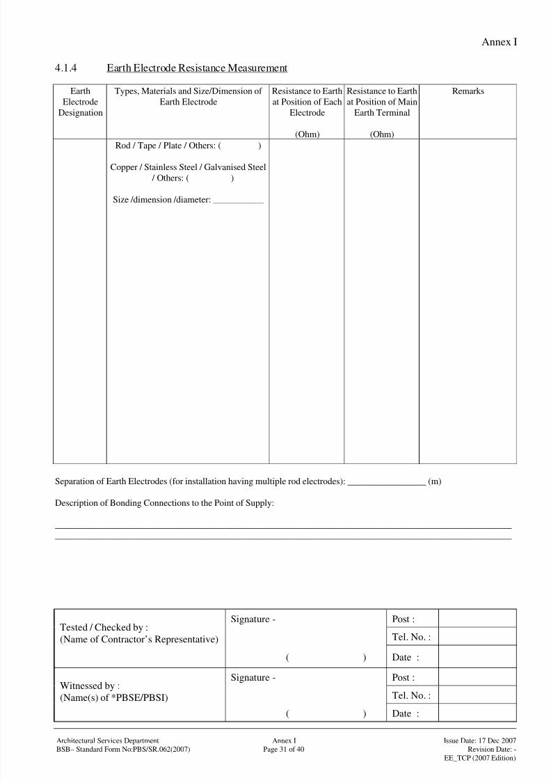
8/4/2019 e102 T&C Procedure of Electrical Installation in Gov Buildings (Hong Kong)
http://slidepdf.com/reader/full/e102-tc-procedure-of-electrical-installation-in-gov-buildings-hong-kong 60/100
Annex I
Signature - Post :
Tel. No. :Tested / Checked by :
(Name of Contractor’s Representative)
( ) Date :
Signature - Post :
Tel. No. :Witnessed by :(Name(s) of *PBSE/PBSI)
( ) Date :
Architectural Services Department Annex I Issue Date: 17 Dec 2007
BSB– Standard Form No:PBS/SR.062(2007) Page 31 of 40 Revision Date: -
EE_TCP (2007 Edition)
4.1.4 Earth Electrode Resistance Measurement
Earth
Electrode
Designation
Types, Materials and Size/Dimension of
Earth Electrode
Resistance to Earth
at Position of Each
Electrode
(Ohm)
Resistance to Earth
at Position of Main
Earth Terminal
(Ohm)
Remarks
Rod / Tape / Plate / Others: ( )
Copper / Stainless Steel / Galvanised Steel
/ Others: ( )
Size /dimension /diameter: ___________
Separation of Earth Electrodes (for installation having multiple rod electrodes): _________________ (m)
Description of Bonding Connections to the Point of Supply:
___________________________________________________________________________________________________
___________________________________________________________________________________________________
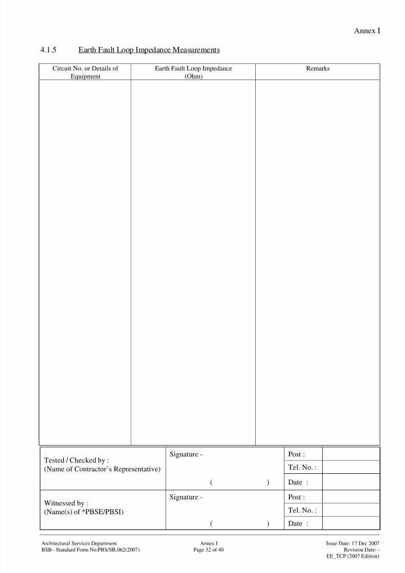
8/4/2019 e102 T&C Procedure of Electrical Installation in Gov Buildings (Hong Kong)
http://slidepdf.com/reader/full/e102-tc-procedure-of-electrical-installation-in-gov-buildings-hong-kong 61/100
Annex I
Signature - Post :
Tel. No. :Tested / Checked by :
(Name of Contractor’s Representative)
( ) Date :
Signature - Post :
Tel. No. :Witnessed by :(Name(s) of *PBSE/PBSI)
( ) Date :
Architectural Services Department Annex I Issue Date: 17 Dec 2007
BSB– Standard Form No:PBS/SR.062(2007) Page 32 of 40 Revision Date: -
EE_TCP (2007 Edition)
4.1.5 Earth Fault Loop Impedance Measurements
Circuit No. or Details of
Equipment
Earth Fault Loop Impedance
(Ohm)
Remarks

8/4/2019 e102 T&C Procedure of Electrical Installation in Gov Buildings (Hong Kong)
http://slidepdf.com/reader/full/e102-tc-procedure-of-electrical-installation-in-gov-buildings-hong-kong 62/100
Annex I
Signature - Post :
Tel. No. :Tested / Checked by :
(Name of Contractor’s Representative)
( ) Date :
Signature - Post :
Tel. No. :Witnessed by :(Name(s) of *PBSE/PBSI)
( ) Date :
Architectural Services Department Annex I Issue Date: 17 Dec 2007
BSB– Standard Form No:PBS/SR.062(2007) Page 33 of 40 Revision Date: -
EE_TCP (2007 Edition)
4.1.6 Functions of All Devices Including Protective Devices
Functional Test of Residual Current Device (RCD)
Test ResultsCircuit No. /Designation of
Protective Devices Built-in test
button(tripped /not
tripped)
50% rated
tripping current(tripped /not
tripped)
Opening time
under 100%rated tripping
current
(ms)
Hand operation
Remarks
Functional check for other protective devices, e.g. MCB, MCCB, ACB, fused switches, switch-fuses and protective relays, etc.
Circuit No. /Designation of
Other Protective Devices
Results of hand operation Remarks
Functional check of all items of equipment such as isolators, switches and indicative devices
Circuit No. /Designation of
Other Protective Devices
Results of hand operation Remarks

8/4/2019 e102 T&C Procedure of Electrical Installation in Gov Buildings (Hong Kong)
http://slidepdf.com/reader/full/e102-tc-procedure-of-electrical-installation-in-gov-buildings-hong-kong 63/100
Annex I
Signature - Post :
Tel. No. :Tested / Checked by :
(Name of Contractor’s Representative)
( ) Date :
Signature - Post :
Tel. No. :Witnessed by :(Name(s) of *PBSE/PBSI)
( ) Date :
Architectural Services Department Annex I Issue Date: 17 Dec 2007
BSB– Standard Form No:PBS/SR.062(2007) Page 34 of 40 Revision Date: -
EE_TCP (2007 Edition)
4.1.7 Additional Checks for Installations in Hazardous Environment
Notes: Details of additional checks for installations in hazardous environment shall be recorded in this form whereas
appropriate.

8/4/2019 e102 T&C Procedure of Electrical Installation in Gov Buildings (Hong Kong)
http://slidepdf.com/reader/full/e102-tc-procedure-of-electrical-installation-in-gov-buildings-hong-kong 64/100
Annex I
Signature - Post :
Tel. No. :Tested / Checked by :
(Name of Contractor’s Representative)
( ) Date :
Signature - Post :
Tel. No. :Witnessed by :(Name(s) of *PBSE/PBSI)
( ) Date :
Architectural Services Department Annex I Issue Date: 17 Dec 2007
BSB– Standard Form No:PBS/SR.062(2007) Page 35 of 40 Revision Date: -
EE_TCP (2007 Edition)
4.2 Test for High Voltage (H.V.) Installations
Notes: Details of test requirements as recommended by manufacturers of relative H.V. equipment /systems shall be
stated and appended here. Test results of respective requirements shall also be recorded and appended in this
form whereas appropriate.
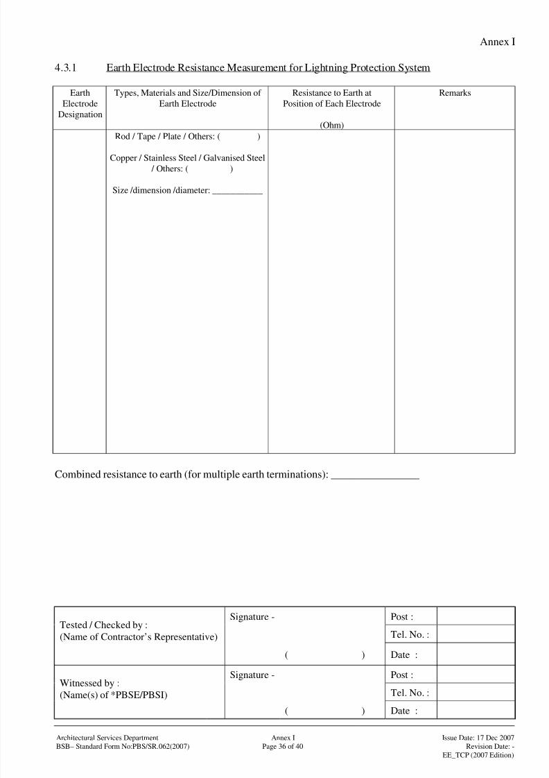
8/4/2019 e102 T&C Procedure of Electrical Installation in Gov Buildings (Hong Kong)
http://slidepdf.com/reader/full/e102-tc-procedure-of-electrical-installation-in-gov-buildings-hong-kong 65/100
Annex I
Signature - Post :
Tel. No. :Tested / Checked by :
(Name of Contractor’s Representative)
( ) Date :
Signature - Post :
Tel. No. :Witnessed by :(Name(s) of *PBSE/PBSI)
( ) Date :
Architectural Services Department Annex I Issue Date: 17 Dec 2007
BSB– Standard Form No:PBS/SR.062(2007) Page 36 of 40 Revision Date: -
EE_TCP (2007 Edition)
4.3.1 Earth Electrode Resistance Measurement for Lightning Protection System
Earth
Electrode
Designation
Types, Materials and Size/Dimension of
Earth Electrode
Resistance to Earth at
Position of Each Electrode
(Ohm)
Remarks
Rod / Tape / Plate / Others: ( )
Copper / Stainless Steel / Galvanised Steel
/ Others: ( )
Size /dimension /diameter: ___________
Combined resistance to earth (for multiple earth terminations): ________________
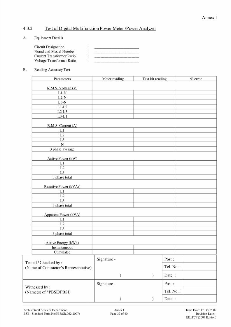
8/4/2019 e102 T&C Procedure of Electrical Installation in Gov Buildings (Hong Kong)
http://slidepdf.com/reader/full/e102-tc-procedure-of-electrical-installation-in-gov-buildings-hong-kong 66/100
Annex I
Signature - Post :
Tel. No. :Tested / Checked by :
(Name of Contractor’s Representative)
( ) Date :
Signature - Post :
Tel. No. :Witnessed by :(Name(s) of *PBSE/PBSI)
( ) Date :
Architectural Services Department Annex I Issue Date: 17 Dec 2007
BSB– Standard Form No:PBS/SR.062(2007) Page 37 of 40 Revision Date: -
EE_TCP (2007 Edition)
4.3.2 Test of Digital Multifunction Power Meter /Power Analyzer
A. Equipment Details
Circuit Designation : _______________________
Brand and Model Number : _______________________
Current Transformer Ratio : _______________________Voltage Transformer Ratio : _______________________
B. Reading Accuracy Test
Parameters Meter reading Test kit reading % error
R.M.S. Voltage (V)
L1-N
L2-N
L3-N
L1-L2
L2-L3
L3-L1
R.M.S. Current (A)
L1
L2
L3
N
3 phase average
Active Power (kW)
L1
L2
L33 phase total
Reactive Power (kVAr)
L1
L2
L3
3 phase total
Apparent Power (kVA)
L1
L2
L33 phase total
Active Energy (kWh)
Instantaneous
Cumulated
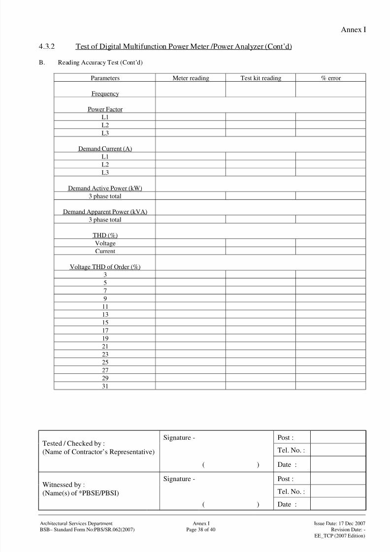
8/4/2019 e102 T&C Procedure of Electrical Installation in Gov Buildings (Hong Kong)
http://slidepdf.com/reader/full/e102-tc-procedure-of-electrical-installation-in-gov-buildings-hong-kong 67/100
Annex I
Signature - Post :
Tel. No. :Tested / Checked by :
(Name of Contractor’s Representative)
( ) Date :
Signature - Post :
Tel. No. :Witnessed by :(Name(s) of *PBSE/PBSI)
( ) Date :
Architectural Services Department Annex I Issue Date: 17 Dec 2007
BSB– Standard Form No:PBS/SR.062(2007) Page 38 of 40 Revision Date: -
EE_TCP (2007 Edition)
4.3.2 Test of Digital Multifunction Power Meter /Power Analyzer (Cont’d)
B. Reading Accuracy Test (Cont’d)
Parameters Meter reading Test kit reading % error
Frequency
Power Factor
L1
L2
L3
Demand Current (A)
L1
L2
L3
Demand Active Power (kW)
3 phase total
Demand Apparent Power (kVA)
3 phase total
THD (%)
Voltage
Current
Voltage THD of Order (%)
3
5
79
11
13
15
17
19
21
23
25
27
29
31

8/4/2019 e102 T&C Procedure of Electrical Installation in Gov Buildings (Hong Kong)
http://slidepdf.com/reader/full/e102-tc-procedure-of-electrical-installation-in-gov-buildings-hong-kong 68/100
Annex I
Signature - Post :
Tel. No. :Tested / Checked by :
(Name of Contractor’s Representative)
( ) Date :
Signature - Post :
Tel. No. :Witnessed by :(Name(s) of *PBSE/PBSI)
( ) Date :
Architectural Services Department Annex I Issue Date: 17 Dec 2007
BSB– Standard Form No:PBS/SR.062(2007) Page 39 of 40 Revision Date: -
EE_TCP (2007 Edition)
4.3.2 Test of Digital Multifunction Power Meter /Power Analyzer (Cont’d)
B. Reading Accuracy Test (Cont’d)
Parameters Meter reading Test kit reading % error
Current THD of Order (%)3
5
7
9
11
13
15
17
19
21
23
25
27
29
31

8/4/2019 e102 T&C Procedure of Electrical Installation in Gov Buildings (Hong Kong)
http://slidepdf.com/reader/full/e102-tc-procedure-of-electrical-installation-in-gov-buildings-hong-kong 69/100
Annex I
Signature - Post :
Tel. No. :Tested / Checked by :
(Name of Contractor’s Representative)
( ) Date :
Signature - Post :
Tel. No. :Witnessed by :(Name(s) of *PBSE/PBSI)
( ) Date :
Architectural Services Department Annex I Issue Date: 17 Dec 2007
BSB– Standard Form No:PBS/SR.062(2007) Page 40 of 40 Revision Date: -
EE_TCP (2007 Edition)
4.4.1 List of Testing Equipment
Type Model Serial No. of
Instrument
Date of
Calibration
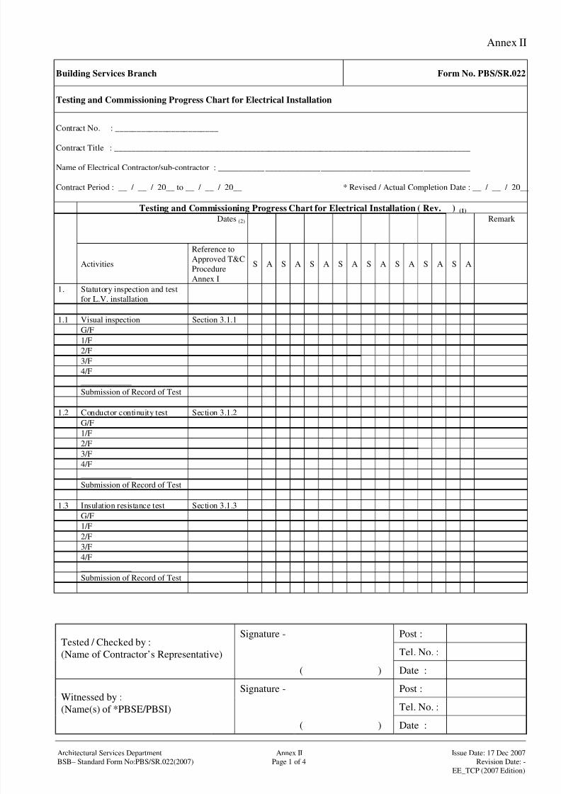
8/4/2019 e102 T&C Procedure of Electrical Installation in Gov Buildings (Hong Kong)
http://slidepdf.com/reader/full/e102-tc-procedure-of-electrical-installation-in-gov-buildings-hong-kong 70/100
Annex II
Signature - Post :
Tel. No. :Tested / Checked by :
(Name of Contractor’s Representative)
( ) Date :
Signature - Post :
Tel. No. :Witnessed by :(Name(s) of *PBSE/PBSI)
( ) Date :
Architectural Services Department Annex II Issue Date: 17 Dec 2007
BSB– Standard Form No:PBS/SR.022(2007) Page 1 of 4 Revision Date: -
EE_TCP (2007 Edition)
Building Services Branch Form No. PBS/SR.022
Testing and Commissioning Progress Chart for Electrical Installation
Contract No. : ________________________
Contract Title : ___________________________________________________________________________________
Name of Electrical Contractor/sub-contractor : ___________________________________________________________
Contract Period : __ / __ / 20__ to __ / __ / 20__ * Revised / Actual Completion Date : __ / __ / 20__
Testing and Commissioning Progress Chart for Electrical Installation ( Rev. ) (1)
Dates (2) Remark
Activities
Reference to
Approved T&C
Procedure
Annex I
S A S A S A S A S A S A S A S A
1. Statutory inspection and test
for L.V. installation
1.1 Visual inspection Section 3.1.1
G/F
1/F
2/F
3/F
4/F
____________
Submission of Record of Test
1.2 Conductor continuity test Section 3.1.2
G/F
1/F
2/F
3/F
4/F
____________
Submission of Record of Test
1.3 Insulation resistance test Section 3.1.3
G/F
1/F
2/F
3/F
4/F____________
Submission of Record of Test
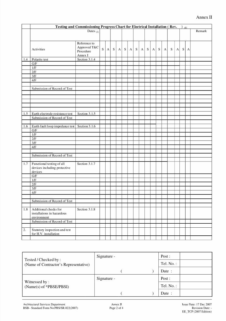
8/4/2019 e102 T&C Procedure of Electrical Installation in Gov Buildings (Hong Kong)
http://slidepdf.com/reader/full/e102-tc-procedure-of-electrical-installation-in-gov-buildings-hong-kong 71/100
Annex II
Signature - Post :
Tel. No. :Tested / Checked by :
(Name of Contractor’s Representative)
( ) Date :
Signature - Post :
Tel. No. :Witnessed by :(Name(s) of *PBSE/PBSI)
( ) Date :
Architectural Services Department Annex II Issue Date: 17 Dec 2007
BSB– Standard Form No:PBS/SR.022(2007) Page 2 of 4 Revision Date: -
EE_TCP (2007 Edition)
Testing and Commissioning Progress Chart for Electrical Installation ( Rev. ) (1)
Dates (2) Remark
Activities
Reference to
Approved T&C
Procedure
Annex I
S A S A S A S A S A S A S A S A
1.4 Polarity test Section 3.1.4
G/F
1/F
2/F
3/F
4/F
____________
Submission of Record of Test
1.5 Earth electrode resistance test Section 3.1.5
Submission of Record of Test
1.6 Earth fault loop impedance test Section 3.1.6
G/F
1/F
2/F
3/F
4/F
____________
Submission of Record of Test
1.7 Functional testing of all
devices including protectivedevices
Section 3.1.7
G/F
1/F
2/F
3/F
4/F
____________
Submission of Record of Test
1.8 Additional checks for
installations in hazardous
environment
Section 3.1.8
Submission of Record of Test
2. Statutory inspection and test
for H.V. installation
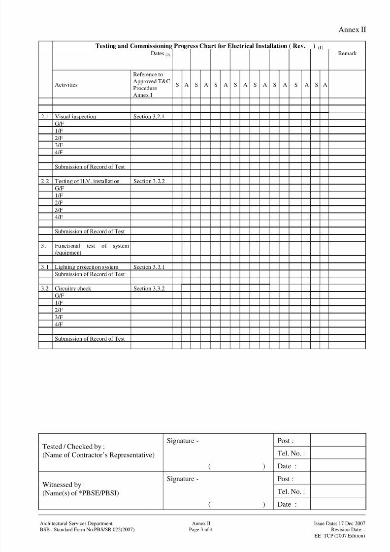
8/4/2019 e102 T&C Procedure of Electrical Installation in Gov Buildings (Hong Kong)
http://slidepdf.com/reader/full/e102-tc-procedure-of-electrical-installation-in-gov-buildings-hong-kong 72/100
Annex II
Signature - Post :
Tel. No. :Tested / Checked by :
(Name of Contractor’s Representative)
( ) Date :
Signature - Post :
Tel. No. :Witnessed by :(Name(s) of *PBSE/PBSI)
( ) Date :
Architectural Services Department Annex II Issue Date: 17 Dec 2007
BSB– Standard Form No:PBS/SR.022(2007) Page 3 of 4 Revision Date: -
EE_TCP (2007 Edition)
Testing and Commissioning Progress Chart for Electrical Installation ( Rev. ) (1)
Dates (2) Remark
Activities
Reference to
Approved T&C
Procedure
Annex I
S A S A S A S A S A S A S A S A
2.1 Visual inspection Section 3.2.1
G/F
1/F
2/F
3/F
4/F
____________
Submission of Record of Test
2.2 Testing of H.V. installation Section 3.2.2
G/F
1/F
2/F
3/F
4/F
____________
Submission of Record of Test
3. Functional test of system
/equipment
3.1 Lighting protection system Section 3.3.1
Submission of Record of Test
3.2 Circuitry check Section 3.3.2G/F
1/F
2/F
3/F
4/F
____________
Submission of Record of Test
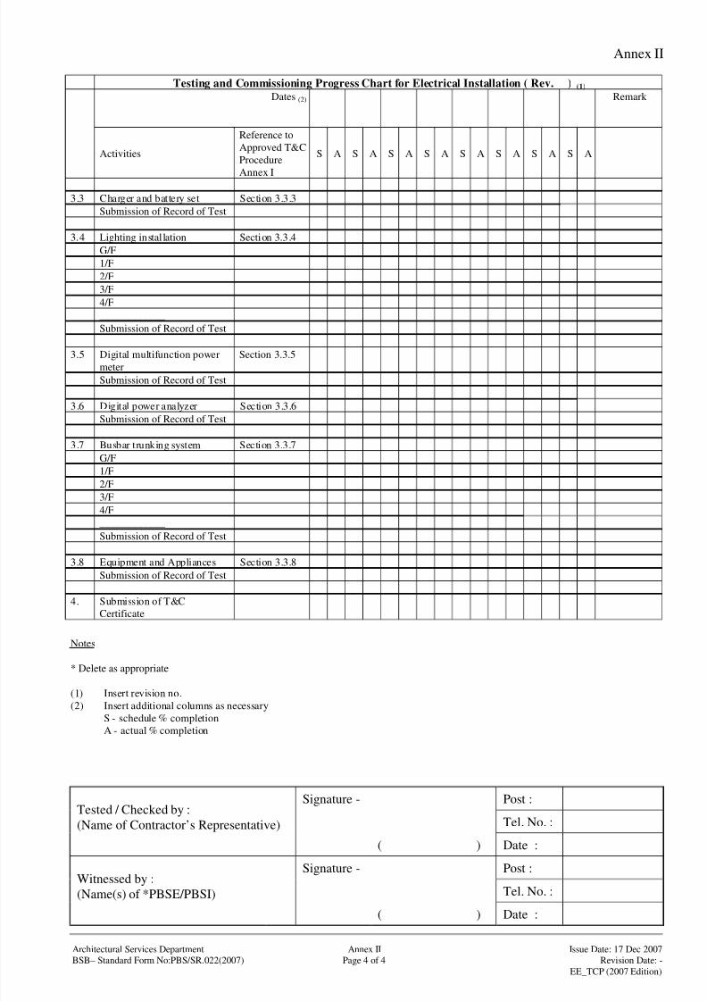
8/4/2019 e102 T&C Procedure of Electrical Installation in Gov Buildings (Hong Kong)
http://slidepdf.com/reader/full/e102-tc-procedure-of-electrical-installation-in-gov-buildings-hong-kong 73/100
Annex II
Signature - Post :
Tel. No. :Tested / Checked by :
(Name of Contractor’s Representative)
( ) Date :
Signature - Post :
Tel. No. :Witnessed by :(Name(s) of *PBSE/PBSI)
( ) Date :
Architectural Services Department Annex II Issue Date: 17 Dec 2007
BSB– Standard Form No:PBS/SR.022(2007) Page 4 of 4 Revision Date: -
EE_TCP (2007 Edition)
Testing and Commissioning Progress Chart for Electrical Installation ( Rev. ) (1)
Dates (2) Remark
Activities
Reference to
Approved T&C
Procedure
Annex I
S A S A S A S A S A S A S A S A
3.3 Charger and battery set Section 3.3.3
Submission of Record of Test
3.4 Lighting installation Section 3.3.4
G/F
1/F
2/F
3/F
4/F
____________
Submission of Record of Test
3.5 Digital multifunction power
meter
Section 3.3.5
Submission of Record of Test
3.6 Digital power analyzer Section 3.3.6
Submission of Record of Test
3.7 Busbar trunking system Section 3.3.7
G/F
1/F
2/F
3/F
4/F
____________Submission of Record of Test
3.8 Equipment and Appliances Section 3.3.8
Submission of Record of Test
4. Submission of T&C
Certificate
Notes
* Delete as appropriate
(1) Insert revision no.
(2) Insert additional columns as necessary
S - schedule % completion
A - actual % completion

8/4/2019 e102 T&C Procedure of Electrical Installation in Gov Buildings (Hong Kong)
http://slidepdf.com/reader/full/e102-tc-procedure-of-electrical-installation-in-gov-buildings-hong-kong 74/100
Annex III
Architectural Services Department Annex III Issue Date: 17 Dec 2007
BSB– Standard Form No:PBS/SR.066(2007) Page 1 of 25 Revision Date: -
EE_TCP (2007 Edition)
Building Services Branch Form No. PBS/SR.066
Testing and Commissioning Certificate on Low Voltage Cubicle Switchboard Installation
Part 1 : Detail of Project
1.1 Project title (with location) :
1.2 * P.W.P. / Project No. :
1.3 * Contract/Sub-contract/Quotation No. :
1.4 * Contractor/Sub-contractor :
1.5 PBSE :
1.6 PBSI :
Part 2 : Declaration
2.1 I certify that the Low Voltage Cubicle Switchboard Installation as specified in the
*Contract/Sub contract//Quotation at the above location has been inspected, tested and
commissioned in accordance with this procedure and/or any other procedures agreed
between the PBSE and the Contractor. The results are satisfactory in the aspects as
mentioned in Part 3 and/or as recorded in Part 4 of this Certificate, except as indicated in
the COMMENTS items.
2.2 I also certify that site tests have been performed in accordance with the requirements set
out in Annex III of this procedure and that the results are satisfactory. A record of thetests has been prepared and submitted to the project BSE.
Signature - Post :
Tel. No. :
(Name of Contractor’s
Representative)
( ) Date :
Signature - Post :
Tel. No. :
(Designation of Contractor’s
Representative)
( ) Date :Signature - Post :
Tel. No. :(Name and Stamp of Contractor)
( ) Date :
Note : This certificate must be signed by a person authorized by the Firm/Company
* Delete if not applicable

8/4/2019 e102 T&C Procedure of Electrical Installation in Gov Buildings (Hong Kong)
http://slidepdf.com/reader/full/e102-tc-procedure-of-electrical-installation-in-gov-buildings-hong-kong 75/100
Annex III
Signature - Post :
Tel. No. :Tested / Checked by :
(Name of Contractor’s Representative)
( ) Date :
Signature - Post :
Tel. No. :Witnessed by :(Name(s) of *PBSE/PBSI)
( ) Date :
Architectural Services Department Annex III Issue Date: 17 Dec 2007
BSB– Standard Form No:PBS/SR.066(2007) Page 2 of 25 Revision Date: -
EE_TCP (2007 Edition)
Items tested /
checked by
Contractor
Items witnessed
by
PBSE/PBSI
Part 3. Items Inspected and Tested
3.1 Visual Inspection
3.1.1 Construction of Type Tested Assembly (TTA)
3.1.1.1 General construction and standard of finishing of TTA are
satisfactory.
*Yes/No/N.A. *Yes/No/N.A.
3.1.1.2 Levelling and alignment of TTA are satisfactory. *Yes/No/N.A. *Yes/No/N.A.
3.1.1.3 The TTA has been properly mounted. *Yes/No/N.A. *Yes/No/N.A.
3.1.1.4 Labels have been properly provided and installed. *Yes/No/N.A. *Yes/No/N.A.
3.1.1.5 Access for maintenance has been allowed. *Yes/No/N.A. *Yes/No/N.A.
3.1.1.6 The layout of the TTA is in conformity with the approved
drawings.
*Yes/No/N.A. *Yes/No/N.A.
3.1.1.7 The physical dimension of the TTA is in conformity with the
approved drawings.
*Yes/No/N.A. *Yes/No/N.A.
3.1.1.8 Danger notices and operation instructions have been adequately
provided.
*Yes/No/N.A. *Yes/No/N.A.
3.1.1.9 Earthing bar and earthing connections have been provided. *Yes/No/N.A. *Yes/No/N.A.
3.1.1.10 Earth wire has been installed for hinged front panels carrying L.V.
equipment.
*Yes/No/N.A. *Yes/No/N.A.
3.1.1.11 The bolts, nuts, washers and screws are of non-ferrous material. *Yes/No/N.A. *Yes/No/N.A.
3.1.1.12 Vermin proof has been satisfactorily provided. *Yes/No/N.A. *Yes/No/N.A.
3.1.1.13 The compartmentation of the TTA conforms with the specified
requirements.
*Yes/No/N.A. *Yes/No/N.A.
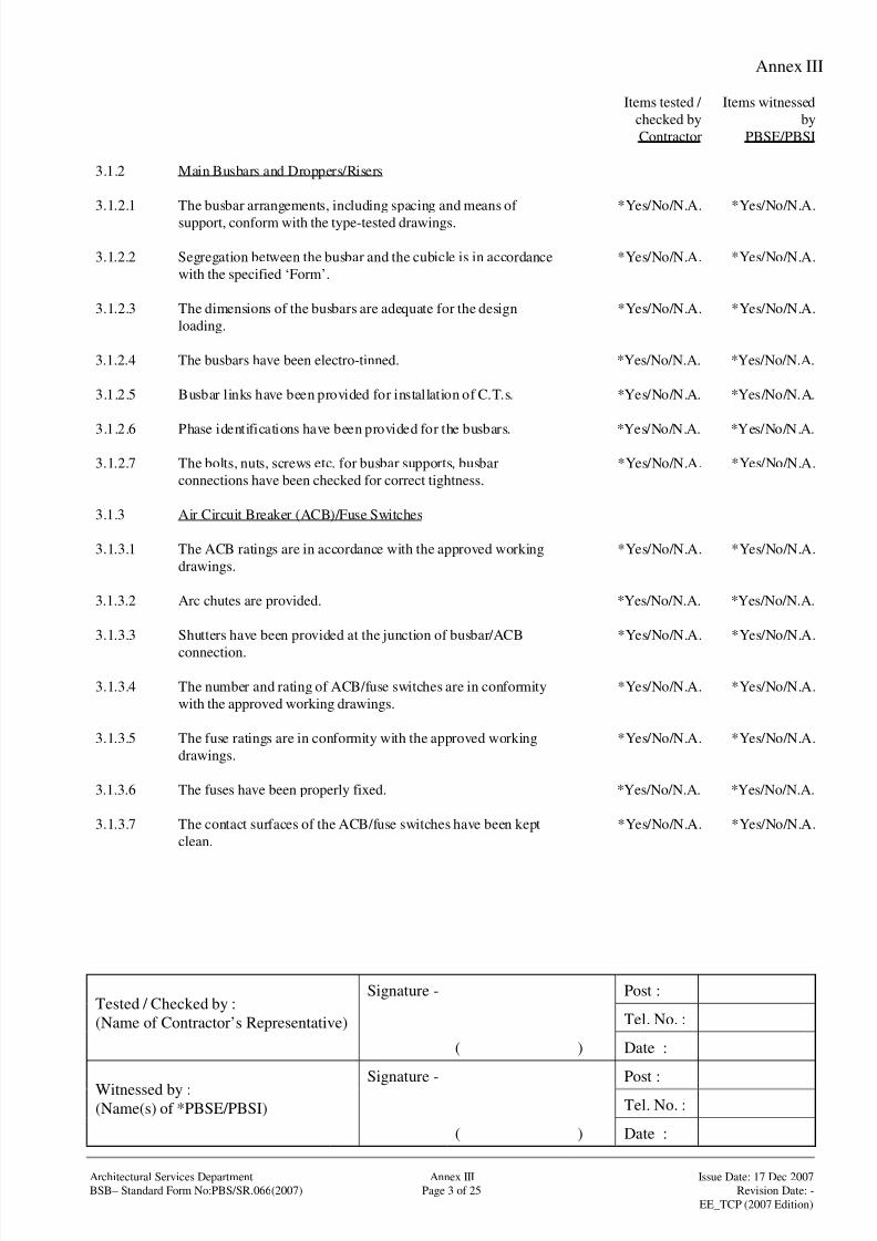
8/4/2019 e102 T&C Procedure of Electrical Installation in Gov Buildings (Hong Kong)
http://slidepdf.com/reader/full/e102-tc-procedure-of-electrical-installation-in-gov-buildings-hong-kong 76/100
Annex III
Signature - Post :
Tel. No. :Tested / Checked by :
(Name of Contractor’s Representative)
( ) Date :
Signature - Post :
Tel. No. :Witnessed by :(Name(s) of *PBSE/PBSI)
( ) Date :
Architectural Services Department Annex III Issue Date: 17 Dec 2007
BSB– Standard Form No:PBS/SR.066(2007) Page 3 of 25 Revision Date: -
EE_TCP (2007 Edition)
Items tested /
checked by
Contractor
Items witnessed
by
PBSE/PBSI
3.1.2 Main Busbars and Droppers/Risers
3.1.2.1 The busbar arrangements, including spacing and means of
support, conform with the type-tested drawings.
*Yes/No/N.A. *Yes/No/N.A.
3.1.2.2 Segregation between the busbar and the cubicle is in accordance
with the specified ‘Form’.
*Yes/No/N.A. *Yes/No/N.A.
3.1.2.3 The dimensions of the busbars are adequate for the design
loading.
*Yes/No/N.A. *Yes/No/N.A.
3.1.2.4 The busbars have been electro-tinned. *Yes/No/N.A. *Yes/No/N.A.
3.1.2.5 Busbar links have been provided for installation of C.T.s. *Yes/No/N.A. *Yes/No/N.A.
3.1.2.6 Phase identifications have been provided for the busbars. *Yes/No/N.A. *Yes/No/N.A.
3.1.2.7 The bolts, nuts, screws etc. for busbar supports, busbar
connections have been checked for correct tightness.
*Yes/No/N.A. *Yes/No/N.A.
3.1.3 Air Circuit Breaker (ACB)/Fuse Switches
3.1.3.1 The ACB ratings are in accordance with the approved working
drawings.
*Yes/No/N.A. *Yes/No/N.A.
3.1.3.2 Arc chutes are provided. *Yes/No/N.A. *Yes/No/N.A.
3.1.3.3 Shutters have been provided at the junction of busbar/ACB
connection.
*Yes/No/N.A. *Yes/No/N.A.
3.1.3.4 The number and rating of ACB/fuse switches are in conformity
with the approved working drawings.
*Yes/No/N.A. *Yes/No/N.A.
3.1.3.5 The fuse ratings are in conformity with the approved working
drawings.
*Yes/No/N.A. *Yes/No/N.A.
3.1.3.6 The fuses have been properly fixed. *Yes/No/N.A. *Yes/No/N.A.
3.1.3.7 The contact surfaces of the ACB/fuse switches have been kept
clean.
*Yes/No/N.A. *Yes/No/N.A.

8/4/2019 e102 T&C Procedure of Electrical Installation in Gov Buildings (Hong Kong)
http://slidepdf.com/reader/full/e102-tc-procedure-of-electrical-installation-in-gov-buildings-hong-kong 77/100
Annex III
Signature - Post :
Tel. No. :Tested / Checked by :
(Name of Contractor’s Representative)
( ) Date :
Signature - Post :
Tel. No. :Witnessed by :(Name(s) of *PBSE/PBSI)
( ) Date :
Architectural Services Department Annex III Issue Date: 17 Dec 2007
BSB– Standard Form No:PBS/SR.066(2007) Page 4 of 25 Revision Date: -
EE_TCP (2007 Edition)
Items tested /
checked by
Contractor
Items witnessed
by
PBSE/PBSI
3.1.4 Instrumentation and Protection
3.1.4.1 The Power Co.’s meter control fuses, meter board, cabling, etc.
have been properly installed.
*Yes/No/N.A. *Yes/No/N.A.
3.1.4.2 The type and range of the measuring instruments including digital
multifunction meters and digital power analyzers are in
accordance with those approved.
*Yes/No/N.A. *Yes/No/N.A.
3.1.4.3 Type and range of protection relays including digital protection
relays are in accordance with those approved.
*Yes/No/N.A. *Yes/No/N.A.
3.1.4.4 The operating voltage of the shunt trip coil complies with the
specification.
*Yes/No/N.A. *Yes/No/N.A.
3.1.4.5 The battery charger and associated control/instrument complywith the specification. *Yes/No/N.A. *Yes/No/N.A.
3.1.4.6 The battery voltage and charging current have been checked and
found satisfactory.
*Yes/No/N.A. *Yes/No/N.A.
3.1.4.7 The capacity of the battery has been tested by tripping the ACB
and results are satisfactory.
*Yes/No/N.A. *Yes/No/N.A.
3.1.4.8 The capacity of the battery for digital multifunction meters/ digital
power analyzers/ digital protection relays has been tested and
results are satisfactory.
*Yes/No/N.A. *Yes/No/N.A.
3.1.4.9 The re-charging time of the battery complies with thespecification.
*Yes/No/N.A. *Yes/No/N.A.
3.1.4.10 The control cables have been properly identified and connected. *Yes/No/N.A. *Yes/No/N.A.
3.1.4.11 Rubber grommets have been provided for holes through which
control cables pass.
*Yes/No/N.A. *Yes/No/N.A.
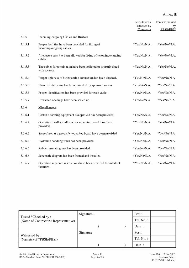
8/4/2019 e102 T&C Procedure of Electrical Installation in Gov Buildings (Hong Kong)
http://slidepdf.com/reader/full/e102-tc-procedure-of-electrical-installation-in-gov-buildings-hong-kong 78/100
Annex III
Signature - Post :
Tel. No. :Tested / Checked by :
(Name of Contractor’s Representative)
( ) Date :
Signature - Post :
Tel. No. :Witnessed by :(Name(s) of *PBSE/PBSI)
( ) Date :
Architectural Services Department Annex III Issue Date: 17 Dec 2007
BSB– Standard Form No:PBS/SR.066(2007) Page 5 of 25 Revision Date: -
EE_TCP (2007 Edition)
Items tested /
checked by
Contractor
Items witnessed
by
PBSE/PBSI
3.1.5 Incoming-outgoing Cables and Busbars
3.1.5.1 Proper facilities have been provided for fixing of
incoming/outgoing cables.
*Yes/No/N.A. *Yes/No/N.A.
3.1.5.2 Adequate space has been allowed for fixing of incoming/outgoing
cables.
*Yes/No/N.A. *Yes/No/N.A.
3.1.5.3 The cables for termination have been soldered or properly fitted
with sockets.
*Yes/No/N.A. *Yes/No/N.A.
3.1.5.4 Proper tightness of busbar/cable connection has been checked. *Yes/No/N.A. *Yes/No/N.A.
3.1.5.5 Phase identification has been provided by approved means. *Yes/No/N.A. *Yes/No/N.A.
3.1.5.6 Proper identification has been provided for each cable. *Yes/No/N.A. *Yes/No/N.A.
3.1.5.7 Unwanted openings have been sealed up. *Yes/No/N.A. *Yes/No/N.A.
3.1.6 Miscellaneous
3.1.6.1 Portable earthing equipment as approved has been provided. *Yes/No/N.A. *Yes/No/N.A.
3.1.6.2 Operating handles and keys c/w mounting board have been
provided.
*Yes/No/N.A. *Yes/No/N.A.
3.1.6.3 Spare fuses as agreed c/w mounting board have been provided. *Yes/No/N.A. *Yes/No/N.A.
3.1.6.4 Hydraulic handling truck has been provided. *Yes/No/N.A. *Yes/No/N.A.
3.1.6.5 Rubber insulating mat has been provided. *Yes/No/N.A. *Yes/No/N.A.
3.1.6.6 Schematic diagram has been framed and installed. *Yes/No/N.A. *Yes/No/N.A.
3.1.6.7 Operation sequence instructions have been provided for interlock
facilities.
*Yes/No/N.A. *Yes/No/N.A.

8/4/2019 e102 T&C Procedure of Electrical Installation in Gov Buildings (Hong Kong)
http://slidepdf.com/reader/full/e102-tc-procedure-of-electrical-installation-in-gov-buildings-hong-kong 79/100
Annex III
Signature - Post :
Tel. No. :Tested / Checked by :
(Name of Contractor’s Representative)
( ) Date :
Signature - Post :
Tel. No. :Witnessed by :(Name(s) of *PBSE/PBSI)
( ) Date :
Architectural Services Department Annex III Issue Date: 17 Dec 2007
BSB– Standard Form No:PBS/SR.066(2007) Page 6 of 25 Revision Date: -
EE_TCP (2007 Edition)
Items tested /
checked by
Contractor
Items witnessed
by
PBSE/PBSI
3.2 Site Tests
3.2.1 Before connection of incoming supply the following tests have
been carried out on site after the L.V. cubicle switchboard has
been properly erected and visually inspected. The results are
satisfactory.
3.2.1.1 Insulation test *Yes/No/N.A. *Yes/No/N.A.
3.2.1.2 Dielectric test *Yes/No/N.A. *Yes/No/N.A.
3.2.1.3 Polarity check for current transformers *Yes/No/N.A. *Yes/No/N.A.
3.2.1.4 Secondary injection test *Yes/No/N.A. *Yes/No/N.A.
3.2.1.5 Primary injection test *Yes/No/N.A. *Yes/No/N.A.
3.2.1.6 Electrical Resistance Test *Yes/No/N.A. *Yes/No/N.A.
3.2.1.7 Temperature-rise Limit Test (at factory / site)* *Yes/No/N.A. *Yes/No/N.A.
3.2.1.8 Functional Test *Yes/No/N.A. *Yes/No/N.A.
3.2.2 After connection of incoming supply the following tests have been
carried out and the results are satisfactory.
3.2.2.1 Voltage test *Yes/No/N.A. *Yes/No/N.A.
3.2.2.2 Phase sequence test *Yes/No/N.A. *Yes/No/N.A.
3.2.2.3 Functional test for digital multifunction power meter /digital
power analyzer
*Yes/No/N.A. *Yes/No/N.A.
3.2.3 The above test results have been recorded in the “Test Records”
as shown in Annex III Part 4 of this procedure.
*Yes/No/N.A. *Yes/No/N.A.

8/4/2019 e102 T&C Procedure of Electrical Installation in Gov Buildings (Hong Kong)
http://slidepdf.com/reader/full/e102-tc-procedure-of-electrical-installation-in-gov-buildings-hong-kong 80/100
Annex III
Signature - Post :
Tel. No. :Tested / Checked by :
(Name of Contractor’s Representative)
( ) Date :
Signature - Post :
Tel. No. :Witnessed by :(Name(s) of *PBSE/PBSI)
( ) Date :
Architectural Services Department Annex III Issue Date: 17 Dec 2007
BSB– Standard Form No:PBS/SR.066(2007) Page 7 of 25 Revision Date: -
EE_TCP (2007 Edition)
Items tested /
checked by
Contractor
Items witnessed
by
PBSE/PBSI
3.3 Any other tests that are considered necessary to meet the design
intent.

8/4/2019 e102 T&C Procedure of Electrical Installation in Gov Buildings (Hong Kong)
http://slidepdf.com/reader/full/e102-tc-procedure-of-electrical-installation-in-gov-buildings-hong-kong 81/100
Annex III
Signature - Post :
Tel. No. :Tested / Checked by :
(Name of Contractor’s Representative)
( ) Date :
Signature - Post :
Tel. No. :Witnessed by :(Name(s) of *PBSE/PBSI)
( ) Date :
Architectural Services Department Annex III Issue Date: 17 Dec 2007
BSB– Standard Form No:PBS/SR.066(2007) Page 8 of 25 Revision Date: -
EE_TCP (2007 Edition)
Items tested /
checked by
Contractor
Items witnessed
by
PBSE/PBSI
3.4 Comments
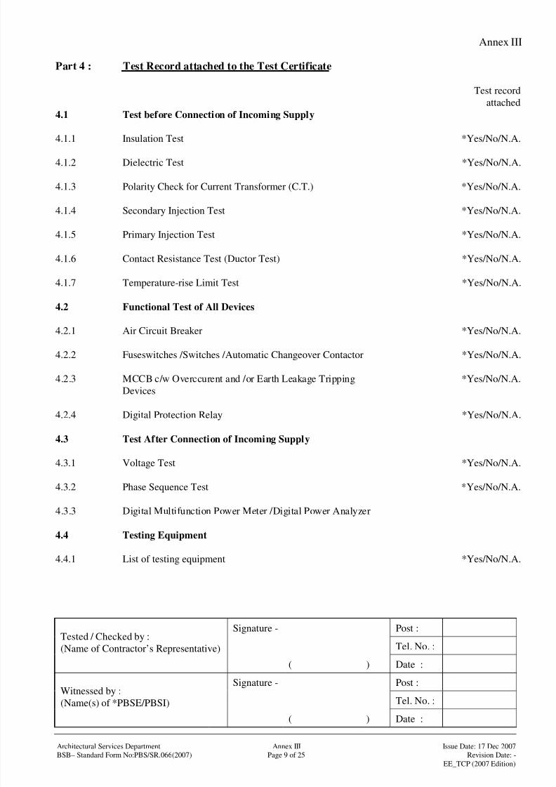
8/4/2019 e102 T&C Procedure of Electrical Installation in Gov Buildings (Hong Kong)
http://slidepdf.com/reader/full/e102-tc-procedure-of-electrical-installation-in-gov-buildings-hong-kong 82/100
Annex III
Signature - Post :
Tel. No. :Tested / Checked by :
(Name of Contractor’s Representative)
( ) Date :
Signature - Post :
Tel. No. :Witnessed by :(Name(s) of *PBSE/PBSI)
( ) Date :
Architectural Services Department Annex III Issue Date: 17 Dec 2007
BSB– Standard Form No:PBS/SR.066(2007) Page 9 of 25 Revision Date: -
EE_TCP (2007 Edition)
Part 4 : Test Record attached to the Test Certificate
Test record
attached
4.1 Test before Connection of Incoming Supply
4.1.1 Insulation Test *Yes/No/N.A.
4.1.2 Dielectric Test *Yes/No/N.A.
4.1.3 Polarity Check for Current Transformer (C.T.) *Yes/No/N.A.
4.1.4 Secondary Injection Test *Yes/No/N.A.
4.1.5 Primary Injection Test *Yes/No/N.A.
4.1.6 Contact Resistance Test (Ductor Test) *Yes/No/N.A.
4.1.7 Temperature-rise Limit Test *Yes/No/N.A.
4.2 Functional Test of All Devices
4.2.1 Air Circuit Breaker *Yes/No/N.A.
4.2.2 Fuseswitches /Switches /Automatic Changeover Contactor *Yes/No/N.A.
4.2.3 MCCB c/w Overccurent and /or Earth Leakage Tripping
Devices
*Yes/No/N.A.
4.2.4 Digital Protection Relay *Yes/No/N.A.
4.3 Test After Connection of Incoming Supply
4.3.1 Voltage Test *Yes/No/N.A.
4.3.2 Phase Sequence Test *Yes/No/N.A.
4.3.3 Digital Multifunction Power Meter /Digital Power Analyzer
4.4 Testing Equipment
4.4.1 List of testing equipment *Yes/No/N.A.
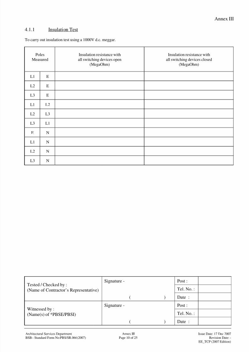
8/4/2019 e102 T&C Procedure of Electrical Installation in Gov Buildings (Hong Kong)
http://slidepdf.com/reader/full/e102-tc-procedure-of-electrical-installation-in-gov-buildings-hong-kong 83/100
Annex III
Signature - Post :
Tel. No. :Tested / Checked by :
(Name of Contractor’s Representative)
( ) Date :
Signature - Post :
Tel. No. :Witnessed by :(Name(s) of *PBSE/PBSI)
( ) Date :
Architectural Services Department Annex III Issue Date: 17 Dec 2007
BSB– Standard Form No:PBS/SR.066(2007) Page 10 of 25 Revision Date: -
EE_TCP (2007 Edition)
4.1.1 Insulation Test
To carry out insulation test using a 1000V d.c. meggar.
Poles
Measured
Insulation resistance with
all switching devices open(MegaOhm)
Insulation resistance with
all switching devices closed(MegaOhm)
L1 E
L2 E
L3 E
L1 L2
L2 L3
L3 L1
E N
L1 N
L2 N
L3 N
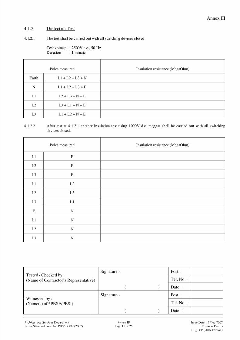
8/4/2019 e102 T&C Procedure of Electrical Installation in Gov Buildings (Hong Kong)
http://slidepdf.com/reader/full/e102-tc-procedure-of-electrical-installation-in-gov-buildings-hong-kong 84/100
Annex III
Signature - Post :
Tel. No. :Tested / Checked by :
(Name of Contractor’s Representative)
( ) Date :
Signature - Post :
Tel. No. :Witnessed by :(Name(s) of *PBSE/PBSI)
( ) Date :
Architectural Services Department Annex III Issue Date: 17 Dec 2007
BSB– Standard Form No:PBS/SR.066(2007) Page 11 of 25 Revision Date: -
EE_TCP (2007 Edition)
4.1.2 Dielectric Test
4.1.2.1 The test shall be carried out with all switching devices closed
Test voltage : 2500V a.c., 50 Hz
Duration : 1 minute
Poles measured Insulation resistance (MegaOhm)
Earth L1 + L2 + L3 + N
N L1 + L2 + L3 + E
L1 L2 + L3 + N + E
L2 L3 + L1 + N + E
L3 L1 + L2 + N + E
4.1.2.2 After test at 4.1.2.1 another insulation test using 1000V d.c. meggar shall be carried out with all switching
devices closed.
Poles measured Insulation resistance (MegaOhm)
L1 E
L2 E
L3 E
L1 L2
L2 L3
L3 L1
E N
L1 N
L2 N
L3 N

8/4/2019 e102 T&C Procedure of Electrical Installation in Gov Buildings (Hong Kong)
http://slidepdf.com/reader/full/e102-tc-procedure-of-electrical-installation-in-gov-buildings-hong-kong 85/100
Annex III
Signature - Post :
Tel. No. :Tested / Checked by :
(Name of Contractor’s Representative)
( ) Date :
Signature - Post :
Tel. No. :Witnessed by :(Name(s) of *PBSE/PBSI)
( ) Date :
Architectural Services Department Annex III Issue Date: 17 Dec 2007
BSB– Standard Form No:PBS/SR.066(2007) Page 12 of 25 Revision Date: -
EE_TCP (2007 Edition)
4.1.3 Polarity Check for Current Transformer (C.T.)
Satisfactory (√ )
Unsatisfactory (X)
NOT completed (NC)NOT applicable (NA)
Remarks
L1
Measurement C.T. L2
L3
N
L1
Protection C.T. L2
L3
N
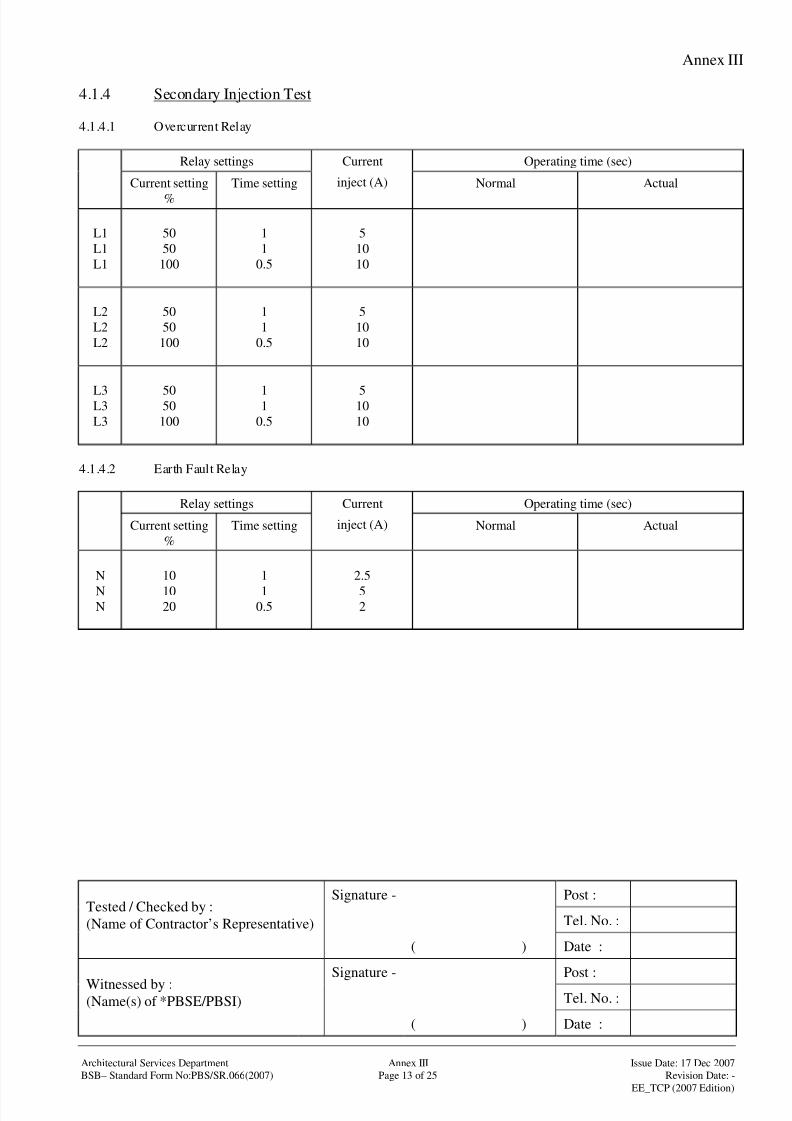
8/4/2019 e102 T&C Procedure of Electrical Installation in Gov Buildings (Hong Kong)
http://slidepdf.com/reader/full/e102-tc-procedure-of-electrical-installation-in-gov-buildings-hong-kong 86/100
Annex III
Signature - Post :
Tel. No. :Tested / Checked by :
(Name of Contractor’s Representative)
( ) Date :
Signature - Post :
Tel. No. :Witnessed by :(Name(s) of *PBSE/PBSI)
( ) Date :
Architectural Services Department Annex III Issue Date: 17 Dec 2007
BSB– Standard Form No:PBS/SR.066(2007) Page 13 of 25 Revision Date: -
EE_TCP (2007 Edition)
4.1.4 Secondary Injection Test
4.1.4.1 Overcurrent Relay
Relay settings Operating time (sec)
Current setting
%
Time setting
Current
inject (A) Normal Actual
L1
L1
L1
50
50
100
1
1
0.5
5
10
10
L2
L2
L2
50
50
100
1
1
0.5
5
10
10
L3L3
L3
5050
100
11
0.5
510
10
4.1.4.2 Earth Fault Relay
Relay settings Operating time (sec)
Current setting
%
Time setting
Current
inject (A) Normal Actual
N
NN
10
1020
1
10.5
2.5
52
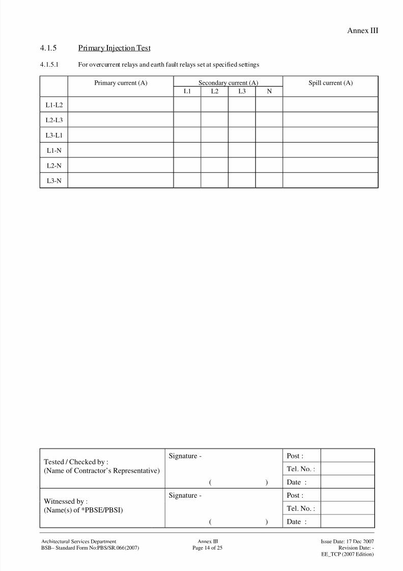
8/4/2019 e102 T&C Procedure of Electrical Installation in Gov Buildings (Hong Kong)
http://slidepdf.com/reader/full/e102-tc-procedure-of-electrical-installation-in-gov-buildings-hong-kong 87/100
Annex III
Signature - Post :
Tel. No. :Tested / Checked by :
(Name of Contractor’s Representative)
( ) Date :
Signature - Post :
Tel. No. :Witnessed by :(Name(s) of *PBSE/PBSI)
( ) Date :
Architectural Services Department Annex III Issue Date: 17 Dec 2007
BSB– Standard Form No:PBS/SR.066(2007) Page 14 of 25 Revision Date: -
EE_TCP (2007 Edition)
4.1.5 Primary Injection Test
4.1.5.1 For overcurrent relays and earth fault relays set at specified settings
Secondary current (A)Primary current (A)
L1 L2 L3 N
Spill current (A)
L1-L2
L2-L3
L3-L1
L1-N
L2-N
L3-N
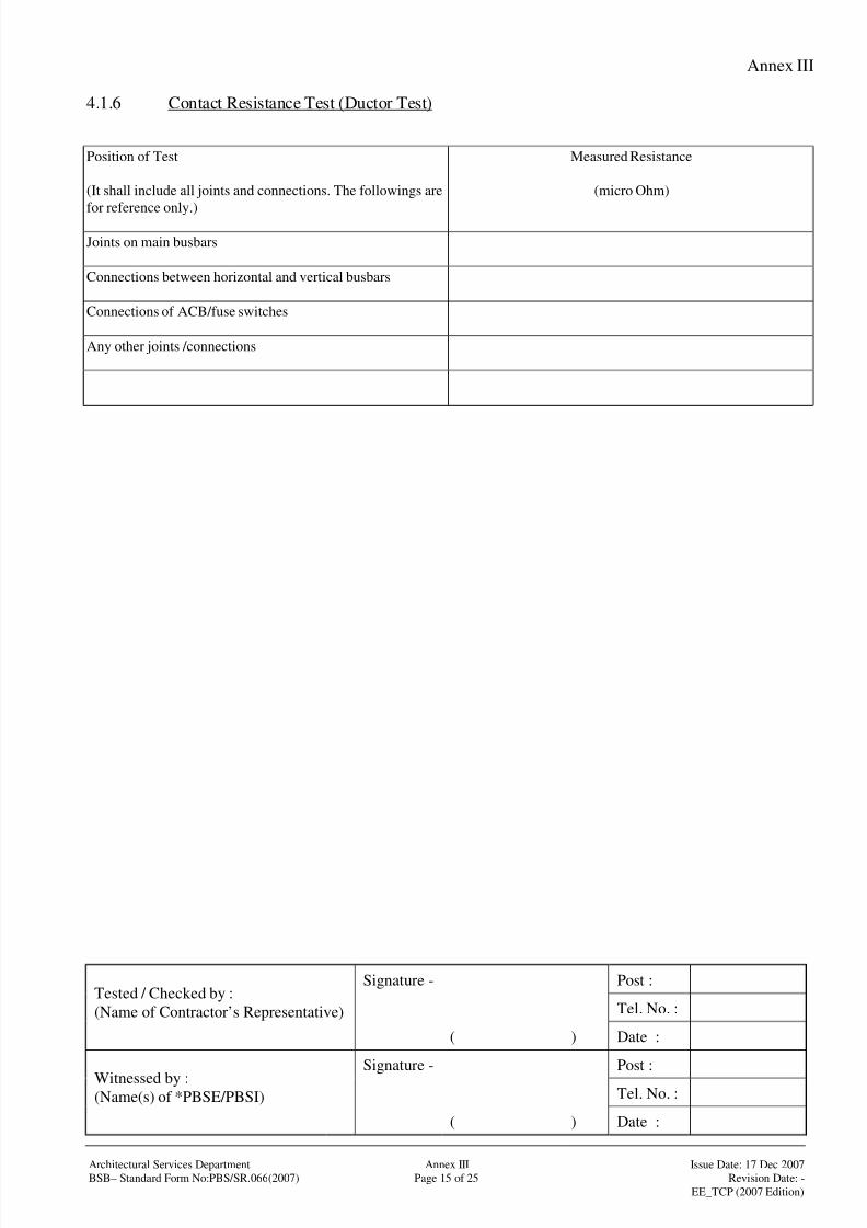
8/4/2019 e102 T&C Procedure of Electrical Installation in Gov Buildings (Hong Kong)
http://slidepdf.com/reader/full/e102-tc-procedure-of-electrical-installation-in-gov-buildings-hong-kong 88/100
Annex III
Signature - Post :
Tel. No. :Tested / Checked by :
(Name of Contractor’s Representative)
( ) Date :
Signature - Post :
Tel. No. :Witnessed by :(Name(s) of *PBSE/PBSI)
( ) Date :
Architectural Services Department Annex III Issue Date: 17 Dec 2007
BSB– Standard Form No:PBS/SR.066(2007) Page 15 of 25 Revision Date: -
EE_TCP (2007 Edition)
4.1.6 Contact Resistance Test (Ductor Test)
Position of Test
(It shall include all joints and connections. The followings are
for reference only.)
Measured Resistance
(micro Ohm)
Joints on main busbars
Connections between horizontal and vertical busbars
Connections of ACB/fuse switches
Any other joints /connections

8/4/2019 e102 T&C Procedure of Electrical Installation in Gov Buildings (Hong Kong)
http://slidepdf.com/reader/full/e102-tc-procedure-of-electrical-installation-in-gov-buildings-hong-kong 89/100
Annex III
Signature - Post :
Tel. No. :Tested / Checked by :
(Name of Contractor’s Representative)
( ) Date :
Signature - Post :
Tel. No. :Witnessed by :(Name(s) of *PBSE/PBSI)
( ) Date :
Architectural Services Department Annex III Issue Date: 17 Dec 2007
BSB– Standard Form No:PBS/SR.066(2007) Page 16 of 25 Revision Date: -
EE_TCP (2007 Edition)
4.1.7 Temperature-rise Limit Test
Ambient Air Temperature at Location 1 ( oC)
Ambient Air Temperature at Location 2 ( oC)
Ambient Air Temperature at Location 3 (oC)
No. Position Temperature Rise
At steady state (oC)
(Positions of test should include all joints and connections. The
followings are for reference only.)
Test Limit
1. Supply connection L1 phase
2. Supply connection L2 phase
3. Supply connection L3 phase
4. Horizontal busbars L1 phase
5. Horizontal busbars L2 phase
6. Horizontal busbars L3 phase
7. Vertical busbars L1 phase
8. Vertical busbars L2 phase
9. Vertical busbars L3 phase
10. Switchgear incoming terminal L1 phase
11. Switchgear incoming terminal L2 phase
12. Switchgear incoming terminal L3 phase
13. Connection busbar to switchgear L1 phase
14. Connection busbar to switchgear L2 phase
15. Connection busbar to switchgear L3 phase
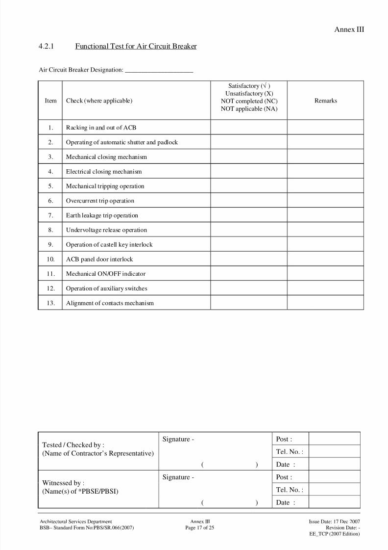
8/4/2019 e102 T&C Procedure of Electrical Installation in Gov Buildings (Hong Kong)
http://slidepdf.com/reader/full/e102-tc-procedure-of-electrical-installation-in-gov-buildings-hong-kong 90/100
Annex III
Signature - Post :
Tel. No. :Tested / Checked by :
(Name of Contractor’s Representative)
( ) Date :
Signature - Post :
Tel. No. :Witnessed by :(Name(s) of *PBSE/PBSI)
( ) Date :
Architectural Services Department Annex III Issue Date: 17 Dec 2007
BSB– Standard Form No:PBS/SR.066(2007) Page 17 of 25 Revision Date: -
EE_TCP (2007 Edition)
4.2.1 Functional Test for Air Circuit Breaker
Air Circuit Breaker Designation: _____________________
Item Check (where applicable)
Satisfactory (√ )
Unsatisfactory (X)NOT completed (NC)
NOT applicable (NA)
Remarks
1. Racking in and out of ACB
2. Operating of automatic shutter and padlock
3. Mechanical closing mechanism
4. Electrical closing mechanism
5. Mechanical tripping operation
6. Overcurrent trip operation
7. Earth leakage trip operation
8. Undervoltage release operation
9. Operation of castell key interlock
10. ACB panel door interlock
11. Mechanical ON/OFF indicator
12. Operation of auxiliary switches
13. Alignment of contacts mechanism

8/4/2019 e102 T&C Procedure of Electrical Installation in Gov Buildings (Hong Kong)
http://slidepdf.com/reader/full/e102-tc-procedure-of-electrical-installation-in-gov-buildings-hong-kong 91/100
Annex III
Signature - Post :
Tel. No. :Tested / Checked by :
(Name of Contractor’s Representative)
( ) Date :
Signature - Post :
Tel. No. :Witnessed by :(Name(s) of *PBSE/PBSI)
( ) Date :
Architectural Services Department Annex III Issue Date: 17 Dec 2007
BSB– Standard Form No:PBS/SR.066(2007) Page 18 of 25 Revision Date: -
EE_TCP (2007 Edition)
4.2.2 Functional Test for Fuse-switches /Switches /Automatic Changeover Contactor
Item Check (where applicable)
Satisfactory (√ )
Unsatisfactory (X)
NOT completed (NC)
NOT applicable (NA)
Remarks
1. Operating of padlock and interlock
2. Mechanical closing mechanism
3. Electrical closing mechanism

8/4/2019 e102 T&C Procedure of Electrical Installation in Gov Buildings (Hong Kong)
http://slidepdf.com/reader/full/e102-tc-procedure-of-electrical-installation-in-gov-buildings-hong-kong 92/100
Annex III
Signature - Post :
Tel. No. :Tested / Checked by :
(Name of Contractor’s Representative)
( ) Date :
Signature - Post :
Tel. No. :Witnessed by :(Name(s) of *PBSE/PBSI)
( ) Date :
Architectural Services Department Annex III Issue Date: 17 Dec 2007
BSB– Standard Form No:PBS/SR.066(2007) Page 19 of 25 Revision Date: -
EE_TCP (2007 Edition)
4.2.3 Functional Test for MCCB c/w Overcurrent and /or Earth Leakage Tripping Devices
Item Check (where applicable)Satisfactory (√ )
Unsatisfactory (X)
NOT completed (NC)
NOT applicable (NA)
Remarks
1. Overcurrent trip operation
2. Earth leakage trip operation

8/4/2019 e102 T&C Procedure of Electrical Installation in Gov Buildings (Hong Kong)
http://slidepdf.com/reader/full/e102-tc-procedure-of-electrical-installation-in-gov-buildings-hong-kong 93/100
Annex III
Signature - Post :
Tel. No. :Tested / Checked by :
(Name of Contractor’s Representative)
( ) Date :
Signature - Post :
Tel. No. :Witnessed by :(Name(s) of *PBSE/PBSI)
( ) Date :
Architectural Services Department Annex III Issue Date: 17 Dec 2007
BSB– Standard Form No:PBS/SR.066(2007) Page 20 of 25 Revision Date: -
EE_TCP (2007 Edition)
4.2.4 Functional Test for Digital Protection Relay
Item Check the following functions (where applicable)
Satisfactory (√ )
Unsatisfactory (X)
NOT completed (NC)
NOT applicable (NA)
Remarks
1. Selection of relay characteristic curves
2. Fault recording function
3. Self-supervision features which monitor the control
circuit of digital relay
4. Remote operation function
5. Communication facilities
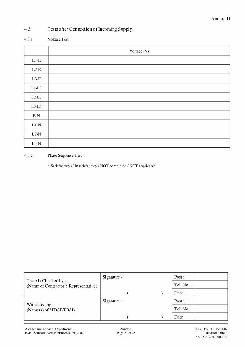
8/4/2019 e102 T&C Procedure of Electrical Installation in Gov Buildings (Hong Kong)
http://slidepdf.com/reader/full/e102-tc-procedure-of-electrical-installation-in-gov-buildings-hong-kong 94/100
Annex III
Signature - Post :
Tel. No. :Tested / Checked by :
(Name of Contractor’s Representative)
( ) Date :
Signature - Post :
Tel. No. :Witnessed by :(Name(s) of *PBSE/PBSI)
( ) Date :
Architectural Services Department Annex III Issue Date: 17 Dec 2007
BSB– Standard Form No:PBS/SR.066(2007) Page 21 of 25 Revision Date: -
EE_TCP (2007 Edition)
4.3 Tests after Connection of Incoming Supply
4.3.1 Voltage Test
Voltage (V)
L1-E
L2-E
L3-E
L1-L2
L2-L3
L3-L1
E-N
L1-N
L2-N
L3-N
4.3.2 Phase Sequence Test
* Satisfactory / Unsatisfactory / NOT completed / NOT applicable
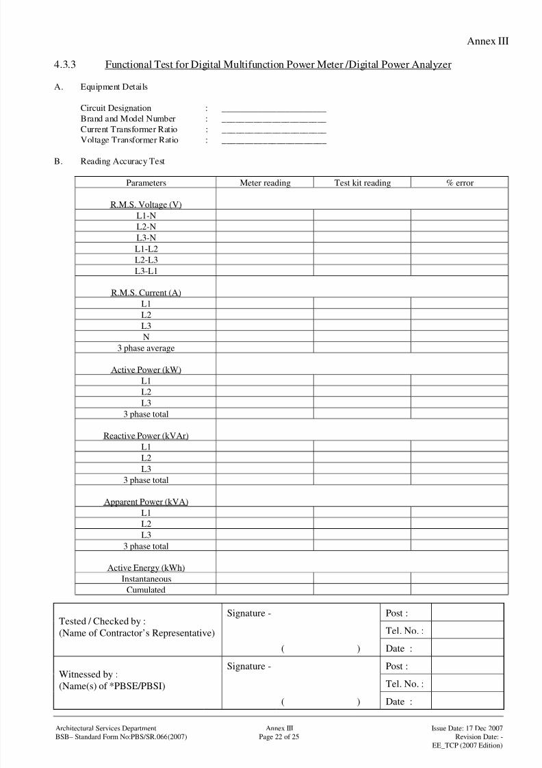
8/4/2019 e102 T&C Procedure of Electrical Installation in Gov Buildings (Hong Kong)
http://slidepdf.com/reader/full/e102-tc-procedure-of-electrical-installation-in-gov-buildings-hong-kong 95/100
Annex III
Signature - Post :
Tel. No. :Tested / Checked by :
(Name of Contractor’s Representative)
( ) Date :
Signature - Post :
Tel. No. :Witnessed by :(Name(s) of *PBSE/PBSI)
( ) Date :
Architectural Services Department Annex III Issue Date: 17 Dec 2007
BSB– Standard Form No:PBS/SR.066(2007) Page 22 of 25 Revision Date: -
EE_TCP (2007 Edition)
4.3.3 Functional Test for Digital Multifunction Power Meter /Digital Power Analyzer
A. Equipment Details
Circuit Designation : _______________________
Brand and Model Number : _______________________
Current Transformer Ratio : _______________________
Voltage Transformer Ratio : _______________________
B. Reading Accuracy Test
Parameters Meter reading Test kit reading % error
R.M.S. Voltage (V)
L1-N
L2-N
L3-N
L1-L2
L2-L3
L3-L1
R.M.S. Current (A)
L1
L2
L3
N
3 phase average
Active Power (kW)
L1
L2
L33 phase total
Reactive Power (kVAr)
L1
L2
L3
3 phase total
Apparent Power (kVA)
L1
L2
L33 phase total
Active Energy (kWh)
Instantaneous
Cumulated
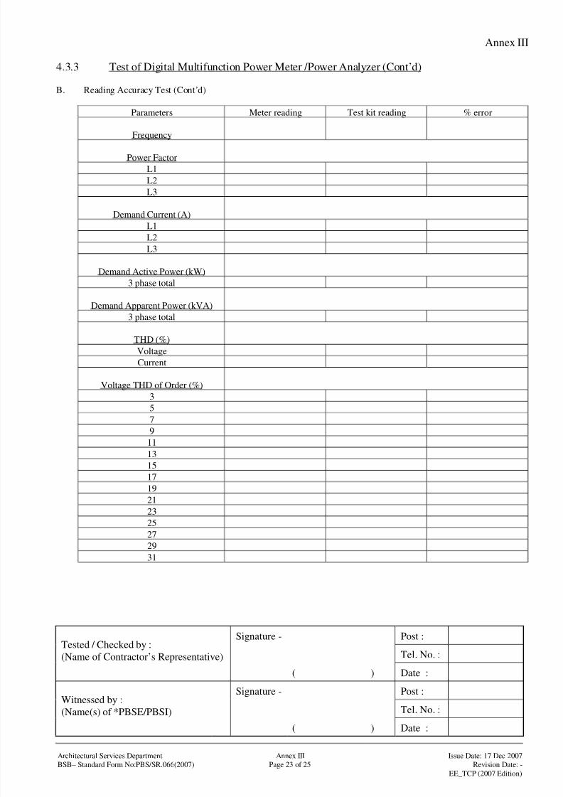
8/4/2019 e102 T&C Procedure of Electrical Installation in Gov Buildings (Hong Kong)
http://slidepdf.com/reader/full/e102-tc-procedure-of-electrical-installation-in-gov-buildings-hong-kong 96/100
Annex III
Signature - Post :
Tel. No. :Tested / Checked by :
(Name of Contractor’s Representative)
( ) Date :
Signature - Post :
Tel. No. :Witnessed by :(Name(s) of *PBSE/PBSI)
( ) Date :
Architectural Services Department Annex III Issue Date: 17 Dec 2007
BSB– Standard Form No:PBS/SR.066(2007) Page 23 of 25 Revision Date: -
EE_TCP (2007 Edition)
4.3.3 Test of Digital Multifunction Power Meter /Power Analyzer (Cont’d)
B. Reading Accuracy Test (Cont’d)
Parameters Meter reading Test kit reading % error
Frequency
Power Factor
L1
L2
L3
Demand Current (A)
L1
L2
L3
Demand Active Power (kW)
3 phase total
Demand Apparent Power (kVA)
3 phase total
THD (%)
Voltage
Current
Voltage THD of Order (%)
3
5
79
11
13
15
17
19
21
23
25
27
29
31

8/4/2019 e102 T&C Procedure of Electrical Installation in Gov Buildings (Hong Kong)
http://slidepdf.com/reader/full/e102-tc-procedure-of-electrical-installation-in-gov-buildings-hong-kong 97/100
Annex III
Signature - Post :
Tel. No. :Tested / Checked by :
(Name of Contractor’s Representative)
( ) Date :
Signature - Post :
Tel. No. :Witnessed by :(Name(s) of *PBSE/PBSI)
( ) Date :
Architectural Services Department Annex III Issue Date: 17 Dec 2007
BSB– Standard Form No:PBS/SR.066(2007) Page 24 of 25 Revision Date: -
EE_TCP (2007 Edition)
4.3.3 Test of Digital Multifunction Power Meter /Power Analyzer (Cont’d)
B. Reading Accuracy Test (Cont’d)
Parameters Meter reading Test kit reading % error
Current THD of Order (%)3
5
7
9
11
13
15
17
19
21
23
25
27
29
31

8/4/2019 e102 T&C Procedure of Electrical Installation in Gov Buildings (Hong Kong)
http://slidepdf.com/reader/full/e102-tc-procedure-of-electrical-installation-in-gov-buildings-hong-kong 98/100
Annex III
Signature - Post :
Tel. No. :Tested / Checked by :
(Name of Contractor’s Representative)
( ) Date :
Signature - Post :
Tel. No. :Witnessed by :(Name(s) of *PBSE/PBSI)
( ) Date :
Architectural Services Department Annex III Issue Date: 17 Dec 2007
BSB– Standard Form No:PBS/SR.066(2007) Page 25 of 25 Revision Date: -
EE_TCP (2007 Edition)
4.4.1 List of Testing Equipment
Type Model Serial No. of
Instrument
Date of Calibration
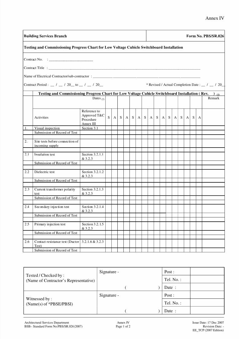
8/4/2019 e102 T&C Procedure of Electrical Installation in Gov Buildings (Hong Kong)
http://slidepdf.com/reader/full/e102-tc-procedure-of-electrical-installation-in-gov-buildings-hong-kong 99/100
Annex IV
Signature - Post :
Tel. No. :Tested / Checked by :
(Name of Contractor’s Representative)
( ) Date :
Signature - Post :Tel. No. :
Witnessed by :
(Name(s) of *PBSE/PBSI)
( ) Date :
Architectural Services Department Annex IV Issue Date: 17 Dec 2007
BSB– Standard Form No:PBS/SR.026(2007) Page 1 of 2 Revision Date: -
EE_TCP (2007 Edition)
Building Services Branch Form No. PBS/SR.026
Testing and Commissioning Progress Chart for Low Voltage Cubicle Switchboard Installation
Contract No. : ________________________
Contract Title : ___________________________________________________________________________________
Name of Electrical Contractor/sub-contractor : ___________________________________________________________
Contract Period : __ / __ / 20__ to __ / __ / 20__ * Revised / Actual Completion Date : __ / __ / 20__
Testing and Commissioning Progress Chart for Low Voltage Cubicle Switchboard Installation ( Rev. ) (1)
Dates (2) Remark
Activities
Reference to
Approved T&C
ProcedureAnnex III
S A S A S A S A S A S A S A S A
1. Visual inspection Section 3.1
Submission of Record of Test
2. Site tests before connection of
incoming supply
2.1 Insulation test Section 3.2.1.1
& 3.2.3
Submission of Record of Test
2.2 Dielectric test Section 3.2.1.2
& 3.2.3
Submission of Record of Test
2.3 Current transformer polarity
test
Section 3.2.1.3
& 3.2.3
Submission of Record of Test
2.4 Secondary injection test Section 3.2.1.4
& 3.2.3
Submission of Record of Test
2.5 Primary injection test Section 3.2.1.5
& 3.2.3
Submission of Record of Test
2.6 Contact resistance test (Ductor
Test)
3.2.1.6 & 3.2.3
Submission of Record of Test

8/4/2019 e102 T&C Procedure of Electrical Installation in Gov Buildings (Hong Kong)
http://slidepdf.com/reader/full/e102-tc-procedure-of-electrical-installation-in-gov-buildings-hong-kong 100/100
Annex IV
Testing and Commissioning Progress Chart for Low Voltage Cubicle Switchboard Installation ( Rev. ) (1)
Dates (2) Remark
Activities
Reference to
Approved T&C
ProcedureAnnex III
S A S A S A S A S A S A S A S A
2.7 Temperature-rise limit test 3.2.1.7 & 3.2.3
Submission of Record of Test
2.8 Functional Test 3.2.1.8 & 3.2.3
Submission of Record of Test
3. Site tests after connection of
incoming supply
3.1 Voltage test 3.2.2.1 & 3.2.3
Submission of Record of Test
3.2 Phase sequence test 3.2.2.3 & 3.2.3
Submission of Record of Test
3.3 Functional test for digital
power meter/power analyzer
4.2.3
Submission of Record of Test
4. Submission of T&C
Certificate
Notes
* Delete as appropriate
(1) Insert revision no.(2) Insert additional columns as necessary
S - schedule % completion
A - actual % completion