e3 and e3 plus electronic overload relays · 2017-03-06 · thermal utilization the e3 overload...
TRANSCRIPT

Bulletin 193-EC
E3 and E3 Plus Electronic Overload Relays
2-226
0
1
2
3
4
5
6
7
8
9
10
11
12
13
� 4 inputs � 2 outputs� PTC thermistor input � DeviceLogix (series B)� External ground fault sensor input
Mounts to Contactor Adjustment Range [A] Cat. No.
100-C09…100-C23
0.4…2.0 193-EC3PB
1…5 193-EC3AB
3…15 193-EC3BB
5…25 193-EC3CB
100-C30…100-C43
1…5 193-EC3AD
3…15 193-EC3BD
5…25 193-EC3CD
9…45 193-EC3DD
100-C60…100-C979…45 193-EC3DE
18…90 193-EC3EE
100-D105…100-D18028…140 � 193-EC3FF
42…210 � 193-EC3GF
100-D210…100-D420
42…210 � 193-EC3GG
60…302 � 193-EC3HG
84…420 � 193-EC3JG
100-D630…100-D860125…630 � 193-EC3KH
172…860 � 193-EC3LH
�Does not include terminal lugs. See Accessories, page 2-228.
Catalog Number Explanation/Product Selection
Catalog Number Explanation
193 – EC1 B Ba b c
aType
Code Description
EC1 E3
EC2 E3 Plus with internal ground fault sensor
EC3 E3 Plus with external ground fault sensor
EC4 E3 Plus current monitor relay withexternal ground fault sensor
EC5� E3 Plus with voltage monitoring
bAdjustment Rating [A]
Code Description
P 0.4…2.0
A 1…5
B 3…15
C 5…25
D 9…45
E 18…90
F 28…140
G 42…210
H 60…302
J 84…420
K 125…630
L 172…860
Z 9…5000
cBulletin 100 Contactor Size
Code Description
B C09…C23
D C30…C43
E C60…C85
F D95…D180
G D210…D420
H D630…D860
Z Panel mount�
� Only available for Cat. Nos. 193-EC1ZZ,193-EC3ZZ, and 193-EC4ZZ. For all other cat.nos., order Cat. No. 193-ECPM_ separately.
� Voltage input module and ribbon cable areincluded with Cat. No. 193-EC5.
� 2 inputs � 1 output
Mounts to Contactor Adjustment Range [A] Cat. No.
100-C09…100-C23
0.4…2 193-EC1PB
1…5 193-EC1AB
3…15 193-EC1BB
5…25 193-EC1CB
100-C30…100-C43
1…5 193-EC1AD
3…15 193-EC1BD
5…25 193-EC1CD
9…45 193-EC1DD
100-C60…100-C979…45 193-EC1DE
18…90 193-EC1EE
100-D105…100-D18028…140 � 193-EC1FF
42…210 � 193-EC1GF
100-D210…100-D420
42…210 � 193-EC1GG
60…302 � 193-EC1HG
84…420 � 193-EC1JG
100-D630…100-D860125…630 � 193-EC1KH
172…860 � 193-EC1LH
�Does not include terminal lugs. See Accessories, page 2-228.
� 4 Inputs � 2 Outputs� PTC thermistor input � DeviceLogix (series B and
higher)� Internal ground fault sensor
Mounts to Contactor Adjustment Range [A] Cat. No.
100-C09…100-C23
0.4…2 193-EC2PB
1…5 193-EC2AB
3…15 193-EC2BB
5…25 193-EC2CB
100-C30…100-C43
1…5 193-EC2AD
3…15 193-EC2BD
5…25 193-EC2CD
9…45 193-EC2DD
100-C60…100-C859…45 193-EC2DE
18…90 193-EC2EE
Direct Contactor Mount
Bulletin 193-EC1 Electronic Motor Protection Relays
Product Selection
Bulletin 193-EC2 Electronic Motor Protection Relay
Bulletin 193-EC3 Electronic Motor Protection Relay
www.ab.com/catalogs Preferred availability cat. nos. are bbold.
Publication A117-CA001A-EN-P
Bulletin 193-EC
E3 and E3 Plus Electronic Overload Relays
2-222
0
1
2
3
4
5
6
7
8
9
10
11
12
13
Overview/Product Selection
Table of Contents
Product Selection ...... 2-226Accessories.................. 2-228Specifications.............. 2-230ApproximateDimensions................... 2-237
Standards ComplianceEN 60947-4-1CSA C22.2 No. 14UL 508, UL1053 (class 1)
Certifications
Product Overview
Feature
E3 EC Plus
193/592-EC1
193/592-EC2
193/592-EC3 193-EC4
193/592-EC5
Inputs� 2 4 4 4 6
Outputs 1 2 2 2 2
PTC Thermistor Input � �
Ground Fault Protection Internal1…5 A
External20 mA…
5 A‡
External20 mA…
5 A‡
External20 mA…
5 A‡
DeviceLogix � � � �
Heat Trace �
Voltage Monitoring �
� Inputs are rated 24V DC.‡ Requires the use of an external ground fault sensor, Cat. No. 193-CBCT_.
ABSCEcULus Listed (File No. E14840,Guide NKCR, NKCR7; File No.E53935, Guide KDAX)C-tickCCC
The E3 Overload Relay is available in two configurations: the E3 andE3 Plus. The following table illustrates the functional differencesbetween the two configurations.
Thermal OverloadThermal UtilizationThe E3 Overload Relay provides overload protection through trueRMS current measurement of the individual phase currents of theconnected motor. Based on this information, a thermal model thatsimulates the actual heating of the motor is calculated. Percent ofthermal capacity utilization (%TCU) reports this calculated value andcan be read via the DeviceNet network. An overload trip occurswhen the value reaches 100%.
Adjustable Settings
Thermal Memory
Time to Trip
Thermal overload protection setup is accomplished simply byprogramming the motor’s full load current (FLC) rating and thedesired trip class (5…30). Programming of the actual values throughsoftware programming ensures the accuracy of the protection.
The E3 Overload Relay includes a thermal memory circuit designedto approximate the thermal decay for a trip class 30 setting. Thismeans that the thermal model of the connected motor is maintainedat all times, even if the supply power is removed.
During an overload condition, the E3 Overload Relay provides anestimated time to trip that is accessible via the DeviceNet network.This allows corrective action to be taken so that production maycontinue uninterrupted.
Time to Reset
Following an overload trip, the E3 Overload Relay will not reset untilthe calculated percentage of thermal capacity utilization falls belowthe reset level. As this value decays, the time to reset, which isaccessible via the DeviceNet network, is reported.
www.ab.com/catalogs Preferred availability cat. nos. are bbold.
Publication A117-CA001A-EN-P
Bul. 193-EC4 CurrentMonitor Relay:
� Current monitoring for threeindependent channels
Bul. 193/592-EC5 OverloadRelays with VoltageMonitoring:
� Features of Bul. 193/592-EC3� Integrated I/O (6 In/2 Out)� High-level (20 mA…5 A)
external ground fault protection� DeviceLogix™ component
technology� Two-speed motor protection� Voltage protection, including:
− Undervoltage− Overvoltage− Phase failure− Voltage unbalance− Phase rotation mismatch− Frequency
� Power protection and energymetering, including:− Real power (kW)− Reactive power (kVAR) − Apparent power (kVA) − Power factor (PF)− Real energy (kWh)− Reactive energy (kVARh)− Apparent energy (kVAh)− kW demand
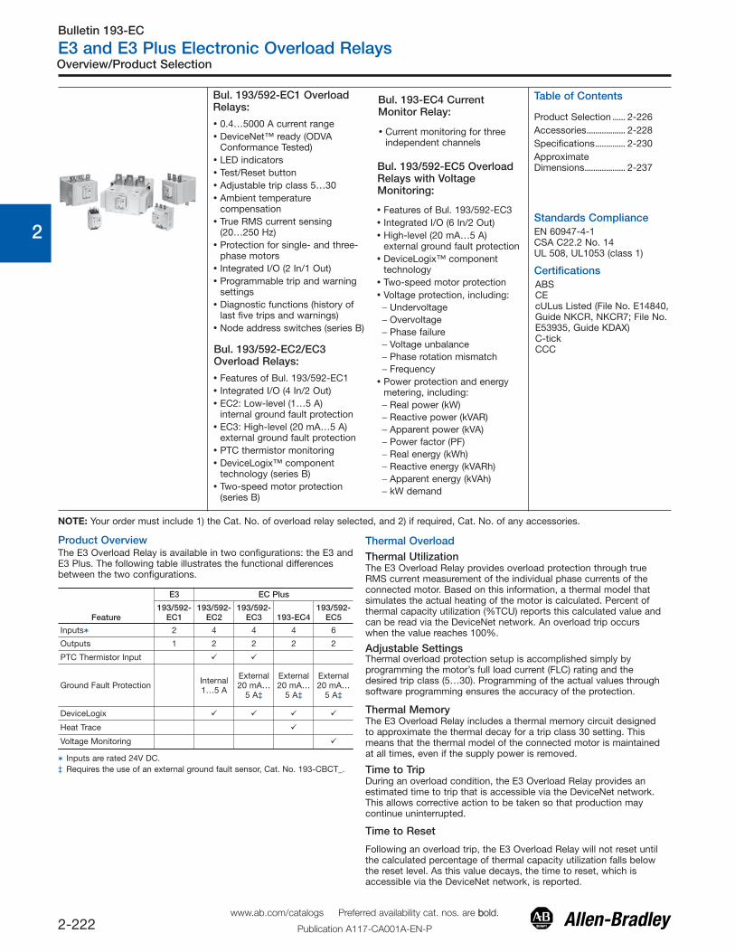
Bul. 193/592-EC1 OverloadRelays:
� 0.4…5000 A current range� DeviceNet™ ready (ODVA
Conformance Tested)� LED indicators� Test/Reset button� Adjustable trip class 5…30� Ambient temperature
compensation� True RMS current sensing
(20…250 Hz)� Protection for single- and three-
phase motors� Integrated I/O (2 In/1 Out)� Programmable trip and warning
settings� Diagnostic functions (history of
last five trips and warnings)� Node address switches (series B)
Bul. 193/592-EC2/EC3Overload Relays:
� Features of Bul. 193/592-EC1� Integrated I/O (4 In/2 Out)� EC2: Low-level (1…5 A)
internal ground fault protection� EC3: High-level (20 mA…5 A)
external ground fault protection� PTC thermistor monitoring� DeviceLogix™ component
technology (series B)� Two-speed motor protection
(series B)
NOTE: Your order must include 1) the Cat. No. of overload relay selected, and 2) if required, Cat. No. of any accessories.
Bulletin 193-EC
E3 and E3 Plus Electronic Overload Relays
2-223
0
1
2
3
4
5
6
7
8
9
10
11
12
13
Inputs/Outputs
� Individual phase currents (in amperes)� Individual phase currents (as a percentage of motor full load
current)� Average current (in amperes)� Average current (as a percentage of motor full load current)� Percentage of thermal capacity utilized� Current imbalance percentage� Ground fault current (E3 Plus)
Product Overview
Thermal Warning
Two-Speed Protection
Phase LossThe E3 Overload Relay offers configurable phase loss protection inallowing the installer to enable or disable the function plus set atime delay setting, adjustable from 0.1…25.0 seconds. The trip levelis factory-set at a current imbalance measurement of 100%.
Ground (Earth) Fault
StallStall is defined as a condition where the motor is not able to reachfull-speed operation in the appropriate amount of time required bythe application. This can result in motor overheating as current drawis in excess of the motor’s full load current rating.The E3 Overload Relay provides user-adjustable stall protection. Thetrip setting has a range of 100…600% FLA, and the enable time isadjustable up to 250 seconds.
Jam (Overcurrent)The E3 Overload Relay can respond quickly to take a motor off-linein the event of a mechanical jam, thereby reducing the potential fordamage to the motor and the power transmission components.Trip adjustments include a trip setting adjustable from 50…600%FLA and a trip delay time with a range of 0.1…25.0 seconds. Aseparate warning setting is adjustable from 50…600% FLA.
Underload (Undercurrent)A sudden drop in motor current can signal conditions such as� Pump cavitation� Tool breakage� Belt breakage
For these instances, rapid fault detection can help minimize damageand aid in reducing production downtime.
Additionally, monitoring for an underload event can provideenhanced protection for motors that are coded by the mediumhandled (e.g., submersible pumps that pump water). Such motorscan become overheated despite being underloaded. This can resultfrom an absence or an insufficient amount of the medium (due toclogged filters, closed valves, etc.).
The E3 Overload Relay offers underload trip and warning settingsadjustable from 10…100% FLA. The trip function also includes atrip delay time with a range of 0.1…25.0 seconds.
Over-temperature ProtectionThe E3 Plus Overload Relay provides motor over-temperatureprotection with the added provisions for terminating and monitoringof stator windingembedded positive temperature coefficient (PTC)thermistors. PTC thermistors are semiconductors that exhibit a largeincrease in resistance when the rated response temperature isexceeded. When the monitored PTC thermistor resistance exceedsthe response level of the E3 Plus Overload Relay (3400 Ω), it can beset to trip immediately or programmed to set the PTC bit of theWarning Status word.
Current Imbalance (Asymmetry)The E3 Plus Overload Relay offers current imbalance trip andwarning settings adjustable from 10…100%. The trip function alsoincludes a trip delay time with a range of 0.1…25.0 seconds.
Remote TripThe remote trip function allows an external device such as avibration sensor to induce the E3 Overload Relay to trip. Externaldevice relay contacts are wired to the E3 Overload Relay discreteiputs. The discrete inputs are configurable with an option forassigning the remote trip function.
Current Monitoring FunctionsThe E3 Overload Relay allows the user to monitor the followingoperational data over the DeviceNet network:
� Device status � History of past five trips� Trip status � History of positive warnings� Warning status � Hours of operation� Time to an overload trip � Number of starts� Time to reset after an overload
trip� Trip snapshot
The E3 Overload Relay allows the user to monitor the followingdiagnostic information over the DeviceNet network:
Diagnostic Functions
Status Indicators
The E3 Plus Overload Relay incorporates zero sequence (corebalance) sensing into its design through the 90 A rating for low level(arcing) ground fault detection. Trip and warning settings areadjustable from 20 mA…5.0 A. For devices rated greater than 90 Aand for ground fault detection less than 1.0 A, the external corebalance current transformer accessory is required. Class Iprotection is provided as defined by UL1053. Series B or laterdevices provide a trip-inhibit setting, offering flexibility to preventtripping when the ground fault current magnitude exceeds 10 A.This can be useful to guard against the opening of the controllerwhen the fault current could potentially exceed the controller'sinterrupting capacity rating.Note: The E3 Plus Overload Relay is not a Ground Fault Circuit
Interrupter for personnel protection as defined in article 100of the U.S. National Electric Code.
The E3 Overload Relay provides the capability to alert in the eventof an impending overload trip. A thermal warning bit is set in theWarning Status when the calculated percentage of thermal capacityutilization exceeds the programmed thermal warning level, whichhas a setting range of 0…100% TCU.
The E3 Plus Overload Relay offers a second FLA setting for 2-speedmotor protection. What used to require two separate overload relays- one for each set of motor windings - can now be accomplishedwith one device. Improved protection is delivered as thermalutilization is maintained in one device during operation in bothspeeds.
The E3 Overload Relay provides the following LED indicators:� Network Status — This green/red LED indicates the status of the
network connection.
� TRIP/WARN — This LED flashes an amber code under a warningcondition and a red code when tripped.
� OUT A & B — These amber LEDs illuminate when the outputcontacts are commanded closed.
� IN 1 - 4 — These amber LEDs illuminate when the user-connecteddevice contact is closed.:Note: IN3 and 4 and OUT B are available only on the E3 Plus
Overload Relay.
Inputs allow the connection of such devices as contactor anddisconnect auxiliary contacts, pilot devices, limit switches, and floatswitches. Input status can be monitored via the network andmapped to a controller’s input image table. Inputs are rated 24V DCand are current sinking. Power for the inputs is sourced from theDeviceNet network connection with convenient customerterminations at control terminals 5 and 6. Relay contact outputs canbe controlled via the network or DeviceLogix function blocks forperforming such tasks as contactor operation.
www.ab.com/catalogs Preferred availability cat. nos. are bbold.
Publication A117-CA001A-EN-P
Bulletin 193-EC
E3 and E3 Plus Electronic Overload Relays
2-224
0
1
2
3
4
5
6
7
8
9
10
11
12
13
Product Overview
Test/Reset Button
Single/Three-Phase Operation
DeviceNet Communications
� Unconnected Message Manager (UCMM) messages� Polled I/O messaging� Change-of-state/cyclic messaging� Explicit messaging� Group 4 — Off-line node recovery messaging� Full parameter object support� Auto-baud network rate identification� Configuration consistency value
DeviceLogix
AC Input Interface Module Accessory
Voltage Protection (model EC5 only)
Power Protection (model EC5 only)
Motor Energy Consumption (model EC5 only)
The Test/Reset button, located on the front of the E3 OverloadRelay, allows the user to perform the following:� Test — The trip relay contact will open if the E3 Overload Relay is
in an untripped condition and the Test/Reset button is pressed for2 seconds or longer.
� Reset — The trip relay contact will close if the E3 Overload Relayis in a tripped condition, supply voltage is present, and theTest/Reset button is pressed.
The E3 Overload Relay can be applied to three-phase as well assingle-phase applications. A programming parameter is provided forselection between single- and three-phase operation. Straight-through wiring is afforded in both cases.
The E3 Overload Relay is a Group 2 “slave only” device andsupports the following:
For more information on operation and maintenance of this product,please reference the user manual, publication 193-UM002*.
The E3 Plus offers increased control flexibility with DeviceLogixcapabilities. Using RSNetWorx for DeviceNet (version 3.0 or later),function block programs can be configured and saved to an E3 PlusOverload Relay to operate single logic routines. The function blocksare programmed using standard Boolean operators (e.g., AND, OR,XOR, and NOT) and plus timers, counters, and latches. In additionto allowing the use of the integral discrete inputs, protectionfunctions can also be used as inputs to trigger outputs. Forexample, the Ground Fault Protection function could be used tocontrol Output A of the E3 Plus Overload Relay for operation of acircuit breaker short-trip mechanism.
The AC Input Interface Module conveniently allows the E3 OverloadRelay to be retrofitted or applied in new applications that require110/120V AC control circuitry. This new accessory simply plugs intothe E3 Overload Relay’s existing input terminals, optimizing panelspace utilization. The module accepts termination of up to fourexternal devices, making it compatible with the E3 and E3 Plusversions of the E3 overload relay. Optical isolation is providedbetween the AC input wiring and the internal 24V circuitry of the E3.
The E3 Plus model EC5 will provide the user with enhanced current-based motor protection just like the E3 Plus model, EC3, with theaddition of voltage protection. With this product, users can protectagainst voltage issues e.g., undervoltage, voltage unbalance, phaseloss, frequency, and phase rotation) before the contactor coil isenergized.
While the motor is powering a load, the E3 Plus model, EC5, willalso protect the motor based on power. This product will monitorand protect for excessive real power (kW), reactive power (kVAR),apparent power (kVA), and power factor for a specific application(e.g., pump applications).
The E3 Plus model, EC5, can be included in a company’s energymanagement system. This product will provide voltage, current,power (kW, kVAR, and kVA), energy (kWh, kVARh, kVAh, kWDemand, kVAR Demand, and kVA Demand), and power quality(power factor, frequency, and phase rotation) information down atthe motor level.
www.ab.com/catalogs Preferred availability cat. nos. are bbold.
Publication A117-CA001A-EN-P
Bulletin 193-EC
E3 and E3 Plus Electronic Overload Relays
2-225
0
1
2
3
4
5
6
7
8
9
10
11
12
13
DeviceNet™ Configuration Terminal (for use with E1 Plus overload relays, E3 and E3 Plus overload relays, ArmorStart®
distributed motor controllers, and Bulletin 825-P modular protection systems)
The DeviceNet Configuration Terminal (Cat. No. 193-DNCT) is a handheld device that can be used to commission, configure, program, andmonitor devices on your DeviceNet network. The 193-DNCT allows you to increase productivity and ease troubleshooting with easy access toinformation and diagnostics of your system. The 193-DNCT can be used with any DeviceNet devices and has DeviceLogix, metering,graphing, and auto-display capabilities. These capabilities can help ease troubleshooting by commissioning devices online through yournetwork.
Network Who� Terminal searches for all devices on the network and provides
device address, device name, and status of a device.
CopyCat™� Used to upload, store, and download device configurations and
DeviceLogix™ programs for DeviceNet devices via your network
� User can easily replace and reconfigure scan lists of DeviceNetscanners (minus the Automatic Device Replacementconfiguration)
� Parameters can be accessed as either groups or as a numberedlist of all parameters, and can be monitored and edited
Diagnostics� Simplifies troubleshooting
� Can present DeviceNet diagnostics, network utilization, and makenetwork statistics available to include baud rate, bus voltage,percentage of bus loading, and CAN errors
DeviceLogix� Terminal allows the user to enable, monitor, edit, or delete
DeviceLogix programs.
EtherNet/IP Communication Auxiliary (for use with E3 and E3 Plus overload relays and Bulletin 825-P modular protection systems)
The EtherNet/IP Communications Auxiliary (Cat. Nos. 193-DNENCAT and -DNCATR) allows users of DeviceNet-based intelligent electronicoverload relays to seamlessly communicate on an EtherNet/IP network without the need for using RSNetWorx for DeviceNet for networkconfiguration. The communication auxiliary acts as a linking device to pass through EtherNet-based CIP explicit and I/O messages to theDeviceNet-based devices. Upon a configuration request, the communication auxiliary polls the DeviceNet network for the first 6 devices. Fordevices that support the full parameter object, parameters will be made available through an internal Web page for the user to view real-timeinformation and configure each device when the user has the appropriate security privileges.
� Users will be able to view and configure parameters using a text file via the internal web page� Allows users to read information into the programmable logic or automation controller� Allows users to use RSLinx Classic or RSLinx Enterprise to serve device Parameters via Microsoft OPC (OLE, Object Linked Element, for
Process Control) to SCADA systems and/or historical data collection systems such as FactoryTalk View, FactoryTalk Historian, andRSEnergyMetrix
� Option to allow users to connect to a DLR (Device Level Ring) network topology− allows the network to choose another physical communication path in the event that the physical link between two EtherNet devices is
broken.� ADR (Automatic Device Replacement) capabilities
− the ADR recognizes when one of the six DeviceNet-based devices has been replaced with a new device, and it will automaticallydownload the previous configuration parameters and node address to the new replacement device
Parameter Monitoring and Editing� If the selected device supports the full parameter object,
parameters can be accessed as either groups or as a numberedlist of all parameters
� Parameter screen displays all information for a single parameter
� Values can be monitored, edited, or copied from the parameterscreen
Product Overview
www.ab.com/catalogs Preferred availability cat. nos. are bbold.
Publication A117-CA001A-EN-P

Bulletin 193-EC
E3 and E3 Plus Electronic Overload Relays
2-227
0
1
2
3
4
5
6
7
8
9
10
11
12
13
Product Selection
� 4 inputs � 2 outputs� External ground fault sensor
input� DeviceLogix
Mounts to Contactor Adjustment Range [A] Cat. No.
100-C09…100-C23
0.4…2.0 193-EC4PB
1…5 193-EC4AB
3…15 193-EC4BB
5…25 193-EC4CB
100-C30…100-C43 9…45 193-EC4DD
100-C60…100-C97 18…90 193-EC4EE
�Does not include terminal lugs. See Accessories, page 2-228.
� 6 inputs � 2 outputs� Voltage monitoring capabilities � DeviceLogix� External ground fault sensor input
Mounts to Contactor Adjustment Range [A] Cat. No.
100-C09…100-C23
0.4…2.0 193-EC5PB
1…5 193-EC5AB
3…15 193-EC5BB
5…25 193-EC5CB
100-C30…100-C435…25 193-EC5CD
9…45 193-EC5DD
100-C60…100-C859…45 193-EC5DE
18…90 193-EC5EE
100-D95…100-D18028…140 193-EC5FF
42…210 193-EC5GF
100-D210…100-D420
42…210 193-EC5GG
60…302 193-EC5HG
84…420 193-EC5JG
100-D630…100-D860125…630 193-EC5KH
172…860 193-EC5LH
�Does not include terminal lugs. See Accessories, page 2-228.
Panel Mount Devices for use with External CurrentTransformers§
Description Adjustment Range [A] Cat. No.
� 2 Inputs� 1 Output
9…5000 193-EC1ZZ
� 4 Inputs� 2 Outputs� Ground Fault Sensor Input� PTC Thermistor Input� DeviceLogix 9…5000
193-EC3ZZ
� 4 Inputs� 2 Outputs� Ground Fault Sensor Input� DeviceLogix
193-EC4ZZ
� 6 Inputs� 2 Outputs� Ground Fault Sensor Input� Voltage Monitor Input� DeviceLogix
9…5000 193-EC5ZZ
§ Current transformers supplied by customer. Refer to Bulletin 1411 CurrentTransformers and the CT Ratio to FLA chart below for proper currenttransformer selection.
CT Ratio to FLA Setting Range Correlation
CT Ratio
FLASetting
Range (A) CT Ratio
FLASetting
Range (A) CT RatioFLA SettingRange (A)
50:5 9…45 300:5 60…302 1200:5 240…1215
100:5 18…90 500:5 84…420 2500:5 450…2250
150:5 28…140 600:5 125…630 5000:5 1000…5000
200:5 42…210 800:5 172…860 — —
Bulletin 193-EC5 Voltage Monitor Relay�
Bulletin 193-EC4 Current Monitor Relay�
Panel Mount Devices
www.ab.com/catalogs Preferred availability cat. nos. are bbold.
Publication A117-CA001A-EN-P
Bulletin 193-EC
E3 and E3 Plus Electronic Overload Relays
2-228
0
1
2
3
4
5
6
7
8
9
10
11
12
13
Accessories
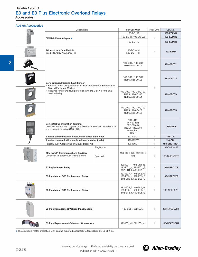
Add-on AccessoriesDescription For Use With Pkg. Qty. Cat. No.
DIN Rail/Panel Adapter♣
193-EC__B
1
193-ECPM1
193-EC_D, 193-EC_ZZ 193-ECPM2
193-EC__E 193-ECPM3
AC Input Interface Modulerated 110/120V AC, 50/60 Hz
193-EC — all592-EC — all 1 193-EIMD
Core Balanced Ground Fault Sensor� Required when using either an E1 Plus Ground Fault Protection or
Ground Fault/Jam Module� Required for ground fault protection with the Cat. No. 193-EC3
overload relay
100-C09…100-C37NEMA size 00…2
1
193-CBCT1
100-C09…100-C97NEMA size 00…3 193-CBCT2
100-C09…100-C97, 100-D105…100-D180NEMA size 00…4
193-CBCT3
100-C09…100-C97, 100-D105…100-D420NEMA size 00…5
193-CBCT4
DeviceNet Configuration TerminalUsed to interface with objects on a DeviceNet network. Includes 1 mcommunications cable (193-CB1).
193-EDN,193-EC (all), 592-EC (all);
280/281/283/284ArmorStart,
825-P
1 193-DNCT
1 meter communication cable, color-coded bare leads 193-DNCT 1 193-CB1
1 meter communication cable, microconnector (male) 193-DNCT 1 193-CM1
Panel Mount Adapter/Door Mount Bezel Kit 193-DNCT 1 193-DNCT-BZ1
EtherNet/IP Communications AuxiliaryDeviceNet to EtherNet/IP linking device
Single port
193-EC_C (all), 592-EC_C(all)
1 193-DNENCAT
Dual port 1 193-DNENCATR
E3 Replacement Relay193-EC1_F, 193-EC1_G,193-EC1_H, 592-EC1_E,592-EC1_F, 592-EC1_G
1 193-NREC1ZZ
E3 Plus Model EC3 Replacement Relay193-EC3_F, 193-EC3_G,193-EC3_H, 592-EC3_E,592-EC3_F, 592-EC3_G
1 193-NREC3ZZ
E3 Plus Model EC5 Replacement Relay193-EC5_F, 193-EC5_G,193-EC5_H, 592-EC5_E,592-EC5_F, 592-EC5_G
1 193-NREC5ZZ
E3 Plus Replacement Voltage Input Module 193-EC5_, 592-EC5_ 1 193-NVEC5VIM
E3 Plus Replacement Cable and Connectors 193-EC_ all, 592-EC_ all 1 193-NCEC5CNT
♣ The electronic motor protection relay can be mounted separately to top-hat rail EN 50 022-35.
www.ab.com/catalogs Preferred availability cat. nos. are bbold.
Publication A117-CA001A-EN-P
Bulletin 193-EC
E3 and E3 Plus Electronic Overload Relays
2-229
0
1
2
3
4
5
6
7
8
9
10
11
12
13
Accessories
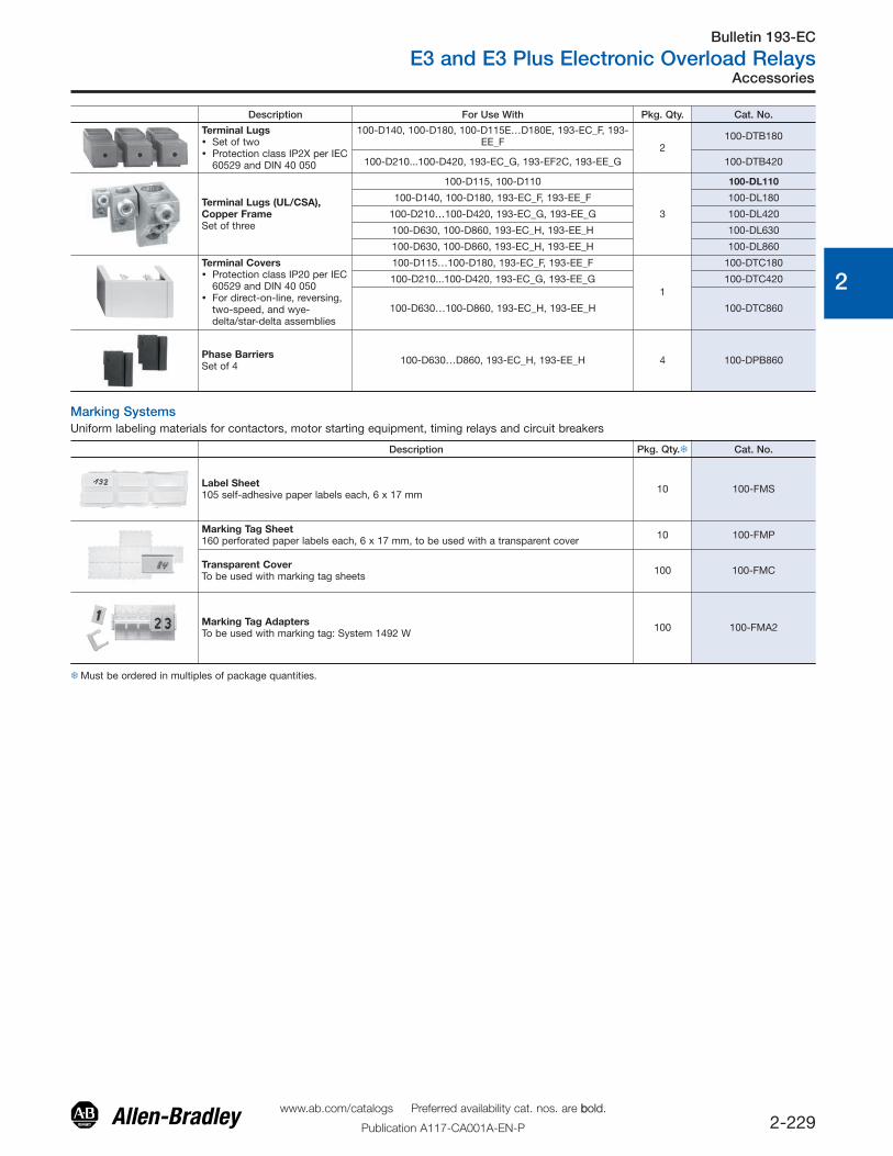
Description For Use With Pkg. Qty. Cat. No.
Terminal Lugs� Set of two� Protection class IP2X per IEC
60529 and DIN 40 050
100-D140, 100-D180, 100-D115E…D180E, 193-EC_F, 193-EE_F 2
100-DTB180
100-D210...100-D420, 193-EC_G, 193-EF2C, 193-EE_G 100-DTB420
Terminal Lugs (UL/CSA),Copper FrameSet of three
100-D115, 100-D110
3
100-DL110
100-D140, 100-D180, 193-EC_F, 193-EE_F 100-DL180
100-D210…100-D420, 193-EC_G, 193-EE_G 100-DL420
100-D630, 100-D860, 193-EC_H, 193-EE_H 100-DL630
100-D630, 100-D860, 193-EC_H, 193-EE_H 100-DL860
Terminal Covers� Protection class IP20 per IEC
60529 and DIN 40 050� For direct-on-line, reversing,
two-speed, and wye-delta/star-delta assemblies
100-D115…100-D180, 193-EC_F, 193-EE_F
1
100-DTC180
100-D210...100-D420, 193-EC_G, 193-EE_G 100-DTC420
100-D630…100-D860, 193-EC_H, 193-EE_H 100-DTC860
Phase BarriersSet of 4 100-D630…D860, 193-EC_H, 193-EE_H 4 100-DPB860
Marking SystemsUniform labeling materials for contactors, motor starting equipment, timing relays and circuit breakers
Description Pkg. Qty.� Cat. No.
Label Sheet105 self-adhesive paper labels each, 6 x 17 mm 10 100-FMS
Marking Tag Sheet160 perforated paper labels each, 6 x 17 mm, to be used with a transparent cover 10 100-FMP
Transparent CoverTo be used with marking tag sheets 100 100-FMC
Marking Tag AdaptersTo be used with marking tag: System 1492 W 100 100-FMA2
�Must be ordered in multiples of package quantities.
www.ab.com/catalogs Preferred availability cat. nos. are bbold.
Publication A117-CA001A-EN-P
Bulletin 193-EC
E3 and E3 Plus Electronic Overload Relays
2-230
0
1
2
3
4
5
6
7
8
9
10
11
12
13
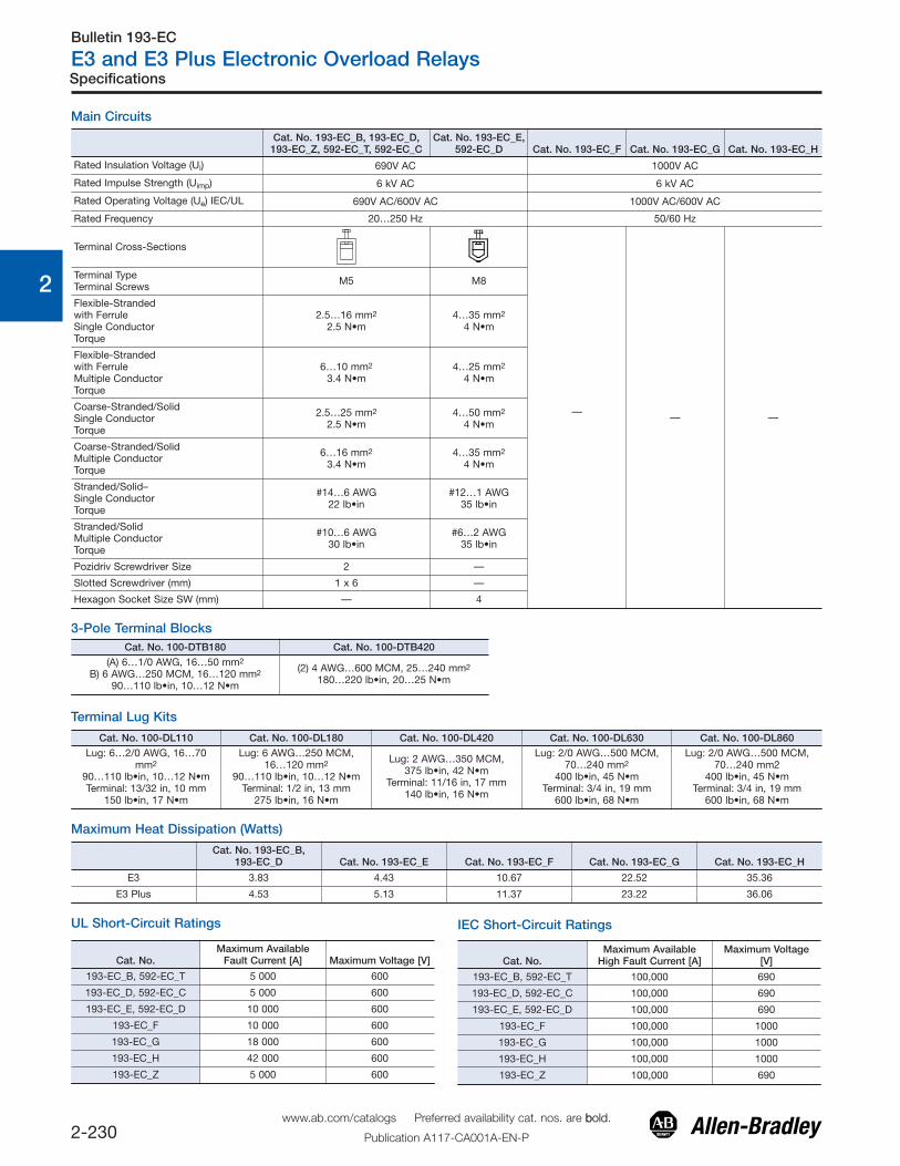
UL Short-Circuit Ratings
Cat. No.Maximum Available
Fault Current [A] Maximum Voltage [V]
193-EC_B, 592-EC_T 5 000 600
193-EC_D, 592-EC_C 5 000 600
193-EC_E, 592-EC_D 10 000 600
193-EC_F 10 000 600
193-EC_G 18 000 600
193-EC_H 42 000 600
193-EC_Z 5 000 600
IEC Short-Circuit Ratings
Cat. No.Maximum Available
High Fault Current [A]Maximum Voltage
[V]
193-EC_B, 592-EC_T 100,000 690
193-EC_D, 592-EC_C 100,000 690
193-EC_E, 592-EC_D 100,000 690
193-EC_F 100,000 1000
193-EC_G 100,000 1000
193-EC_H 100,000 1000
193-EC_Z 100,000 690
Specifications
Main Circuits
Cat. No. 193-EC_B, 193-EC_D,193-EC_Z, 592-EC_T, 592-EC_C
Cat. No. 193-EC_E,592-EC_D Cat. No. 193-EC_F Cat. No. 193-EC_G Cat. No. 193-EC_H
Rated Insulation Voltage (Ui) 690V AC 1000V AC
Rated Impulse Strength (Uimp) 6 kV AC 6 kV AC
Rated Operating Voltage (Ue) IEC/UL 690V AC/600V AC 1000V AC/600V AC
Rated Frequency 20…250 Hz 50/60 Hz
Terminal Cross-Sections
— — —
Terminal TypeTerminal Screws M5 M8
Flexible-Strandedwith FerruleSingle ConductorTorque
2.5…16 mm2
2.5 N•m4…35 mm2
4 N•m
Flexible-Strandedwith FerruleMultiple ConductorTorque
6…10 mm2
3.4 N•m4…25 mm2
4 N•m
Coarse-Stranded/SolidSingle Conductor Torque
2.5…25 mm2
2.5 N•m4…50 mm2
4 N•m
Coarse-Stranded/SolidMultiple ConductorTorque
6…16 mm2
3.4 N•m4…35 mm2
4 N•m
Stranded/Solid–Single ConductorTorque
#14…6 AWG22 lb•in
#12…1 AWG35 lb•in
Stranded/SolidMultiple ConductorTorque
#10…6 AWG30 lb•in
#6…2 AWG35 lb•in
Pozidriv Screwdriver Size 2 —
Slotted Screwdriver (mm) 1 x 6 —
Hexagon Socket Size SW (mm) — 4
3-Pole Terminal BlocksCat. No. 100-DTB180 Cat. No. 100-DTB420
(A) 6…1/0 AWG, 16…50 mm2
B) 6 AWG…250 MCM, 16…120 mm2
90…110 lb•in, 10…12 N•m
(2) 4 AWG…600 MCM, 25…240 mm2
180…220 lb•in, 20…25 N•m
Terminal Lug Kits
Cat. No. 100-DL110 Cat. No. 100-DL180 Cat. No. 100-DL420 Cat. No. 100-DL630 Cat. No. 100-DL860Lug: 6…2/0 AWG, 16…70
mm2
90…110 lb•in, 10…12 N•mTerminal: 13/32 in, 10 mm
150 lb•in, 17 N•m
Lug: 6 AWG…250 MCM,16…120 mm2
90…110 lb•in, 10…12 N•mTerminal: 1/2 in, 13 mm
275 lb•in, 16 N•m
Lug: 2 AWG…350 MCM,375 lb•in, 42 N•m
Terminal: 11/16 in, 17 mm140 lb•in, 16 N•m
Lug: 2/0 AWG…500 MCM,70…240 mm2
400 lb•in, 45 N•mTerminal: 3/4 in, 19 mm
600 lb•in, 68 N•m
Lug: 2/0 AWG…500 MCM,70…240 mm2
400 lb•in, 45 N•mTerminal: 3/4 in, 19 mm
600 lb•in, 68 N•m
Maximum Heat Dissipation (Watts)
Cat. No. 193-EC_B,193-EC_D Cat. No. 193-EC_E Cat. No. 193-EC_F Cat. No. 193-EC_G Cat. No. 193-EC_H
E3 3.83 4.43 10.67 22.52 35.36
E3 Plus 4.53 5.13 11.37 23.22 36.06
www.ab.com/catalogs Preferred availability cat. nos. are bbold.
Publication A117-CA001A-EN-P
Bulletin 193-EC
E3 and E3 Plus Electronic Overload Relays
2-231
0
1
2
3
4
5
6
7
8
9
10
11
12
13
Specifications
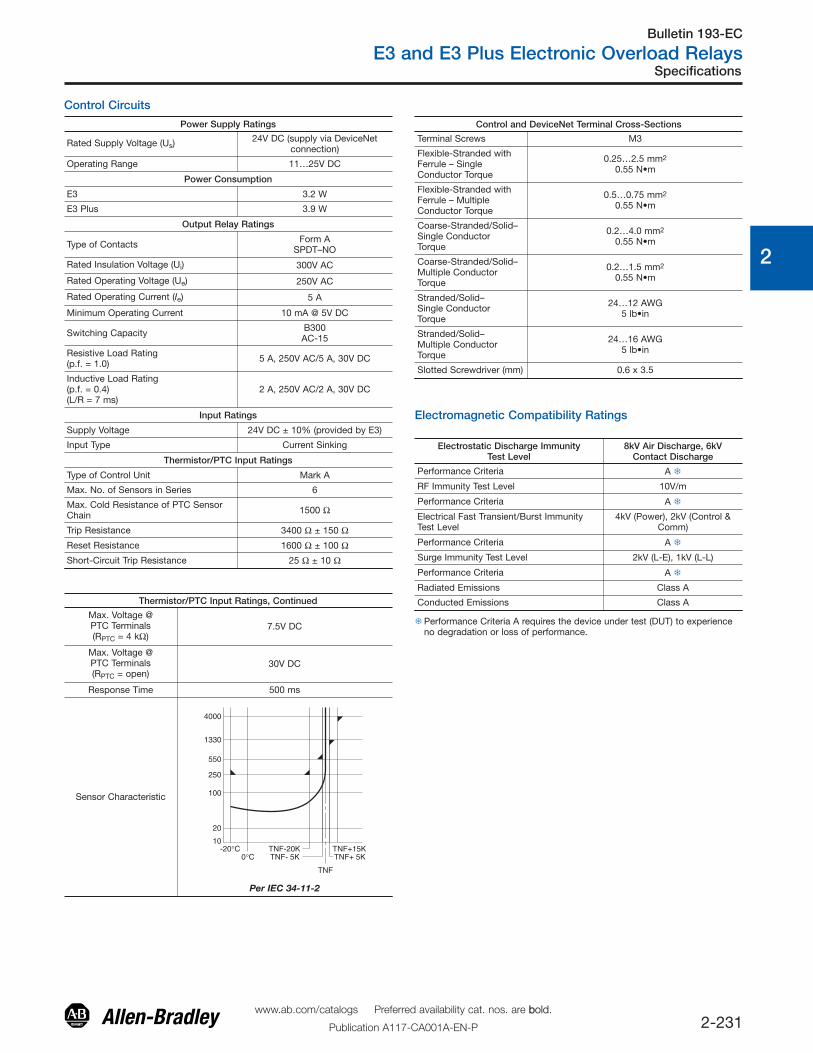
Control Circuits
Power Supply Ratings
Rated Supply Voltage (Us)24V DC (supply via DeviceNet
connection)
Operating Range 11…25V DC
Power Consumption
E3 3.2 W
E3 Plus 3.9 W
Output Relay Ratings
Type of Contacts Form ASPDT–NO
Rated Insulation Voltage (Ui) 300V AC
Rated Operating Voltage (Ue) 250V AC
Rated Operating Current (Ie) 5 A
Minimum Operating Current 10 mA @ 5V DC
Switching Capacity B300AC-15
Resistive Load Rating(p.f. = 1.0) 5 A, 250V AC/5 A, 30V DC
Inductive Load Rating(p.f. = 0.4)(L/R = 7 ms)
2 A, 250V AC/2 A, 30V DC
Input Ratings
Supply Voltage 24V DC ± 10% (provided by E3)
Input Type Current Sinking
Thermistor/PTC Input Ratings
Type of Control Unit Mark A
Max. No. of Sensors in Series 6
Max. Cold Resistance of PTC SensorChain 1500 Ω
Trip Resistance 3400 Ω ± 150 ΩReset Resistance 1600 Ω ± 100 ΩShort-Circuit Trip Resistance 25 Ω ± 10 Ω
Thermistor/PTC Input Ratings, Continued
Max. Voltage @PTC Terminals(RPTC = 4 kΩ)
7.5V DC
Max. Voltage @PTC Terminals(RPTC = open)
30V DC
Response Time 500 ms
Sensor Characteristic
10
20
100
250
550
1330
4000
-20°C TNF-20K0°C TNF- 5K
TNF+15KTNF+ 5K
TNF
Per IEC 34-11-2
Control and DeviceNet Terminal Cross-Sections
Terminal Screws M3
Flexible-Stranded withFerrule – SingleConductor Torque
0.25…2.5 mm2
0.55 N•m
Flexible-Stranded withFerrule – MultipleConductor Torque
0.5…0.75 mm2
0.55 N•m
Coarse-Stranded/Solid–Single ConductorTorque
0.2…4.0 mm2
0.55 N•m
Coarse-Stranded/Solid–Multiple Conductor Torque
0.2…1.5 mm2
0.55 N•m
Stranded/Solid–Single ConductorTorque
24…12 AWG5 lb•in
Stranded/Solid–Multiple ConductorTorque
24…16 AWG5 lb•in
Slotted Screwdriver (mm) 0.6 x 3.5
Electromagnetic Compatibility Ratings
Electrostatic Discharge ImmunityTest Level
8kV Air Discharge, 6kVContact Discharge
Performance Criteria A �
RF Immunity Test Level 10V/m
Performance Criteria A �
Electrical Fast Transient/Burst ImmunityTest Level
4kV (Power), 2kV (Control &Comm)
Performance Criteria A �
Surge Immunity Test Level 2kV (L-E), 1kV (L-L)
Performance Criteria A �
Radiated Emissions Class A
Conducted Emissions Class A
�Performance Criteria A requires the device under test (DUT) to experienceno degradation or loss of performance.
www.ab.com/catalogs Preferred availability cat. nos. are bbold.
Publication A117-CA001A-EN-P

Bulletin 193-EC
E3 and E3 Plus Electronic Overload Relays
2-232
0
1
2
3
4
5
6
7
8
9
10
11
12
13
Specifications
Environmental Ratings
Ambient TemperatureStorageOperating
-40…+85 °C (-40…+185 °F)-20…+55 °C (-4…+131 °F)
HumidityOperatingDamp Heat – Steady-State (per IEC 68-2-3)Damp Heat – Cyclic(per IEC 68-2-30)
5…95% Non-condensing92% r.h., 40 °C(104 °F), 56 days
93% r.h., 25 °C/40 °C(77 °F/104 °F), 21 cycles
Vibration (per IEC 68-2-6) 3 G
Shock (per IEC 68-2-27) 30 G
Pollution Environment Degree 2
Degree of Protection193-ECxxx592-ECxxx
1P1X1P0
Current Reporting Accuracy
Phase Currents:100% min. FLA Setting Value … 720% max. FLA SettingValue50%…100% min FLA Setting Value
+/- 5%+/- 10%
Ground Current (0.5…9.0 A) +/- 10%
External Current Transformers(for use with Cat. Nos. 193-EC1ZZ1, 193-EC3ZZ,193-EC4ZZ, and 193-EC5ZZ)The user shall provide one current transformer (CT) for each motorphase,and shall connect the CT’s secondary leads to theappropriate E3 overload relay power terminals, as shown in currenttransformer’s wiring diagrams. The CT shall have the appropriateratio (refer to the product nameplate or product description).Additionally, the CT shall be selected to be capable of providing therequired VA to the secondary load, which includes the E3 overloadrelay burden of 0.1 VA at the rated secondary current and the wiringburden. Finally, the CT shall be rated for protective relaying toaccomodate the high inrush currents associated with motor startup,and shall have an accuracy of <±2% over its normal operatingrange. Typical CT ratings include (Instrument Transformers, Inc. —Model #23 or equivalent):
ANSI (USA) Class C5B0.1
CSA (Canada) Class 10L5
IEC (Europe) 5 VA Class 5P10
General
Cat. No. 193-EC_B, 193-EC_D, 193-EC_Z Cat. No. 193-EC_E Cat. No. 193-EC_F Cat. No. 193-EC_G Cat. No. 193-EC_H
ApproximateWeights
0.80 kg(1.77 lb)
1.23 kg(2.71 lb)
2.95 kg(6.5 lb)
4.43 kg(9.75 lb)
8.63 kg(19.0 lb)
Standards CSA C22.2 No.14, DIN VDE 0660, EN 60 947, UL 508, UL 1053
Certifications CE, C-tick, cUL, CCC (pending)
Protection and Warning Summary
ProtectiveFunction
Trip EnableWarningEnable Trip Level Settings Trip Delay Settings Warning Level Settings
Inhibit TimeSettings�
FactoryDefault
FactoryDefault Range Default
Range[s]
Default[s] Range Default
Range[s]
Default[s]
ThermalOverload Enabled Disabled 0.4…5000 A — Trip Class
5…30Trip Class
100…100%TCU 85% — —
Phase Loss Enabled — ‡ ‡ 0.1…25.0 1.0 — — 0…250 0
Ground (Earth)Fault Disabled Disabled 1.0…5.0 A 2.5 A 0.1…25.0 0.5 1.0…5.0 A 2.0 A 0…250 10
Stall(High Overload During Start)
Disabled — 100…600% FLA §
600% FLA § 0…250 § 10§ — — — —
Jam(High Overload
During Run)Disabled Disabled 50…600
% FLA 250 % FLA 0.1…25.0 5.0 50…600 %FLA 150 % FLA 0…250 10
Underload Disabled Disabled 10…100% FLA 50 % FLA 0.1…25.0 5.0 10…100 %
FLA 70 % FLA 0…250 10
PTC Disabled Disabled — — — — — — — —
CurrentImbalance
(Asymmetry)Disabled Disabled 10…100% 35% 0.1…25.0 5.0 10…100% 20% 0…250 10
Comm Fault Enabled Disabled — — — — — — — —
Comm Idle Disabled Disabled — — — — — — — —
§ Inhibit time settings are used for both trip and warning functions.‡ Phase loss trip level is set at a current imbalance greater than or equal to 100% and is not user adjustable.�Stall protection is only applicable to the motor starting sequence.
www.ab.com/catalogs Preferred availability cat. nos. are bbold.
Publication A117-CA001A-EN-P
Bulletin 193-EC
E3 and E3 Plus Electronic Overload Relays
2-233
0
1
2
3
4
5
6
7
8
9
10
11
12
13
Specifications
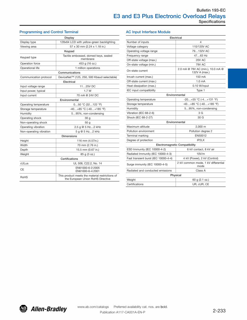
Programming and Control Terminal
Display
Display type 128x64 LCD with yellow-green backlighting
Viewing area 57 x 30 mm (2.24 x 1.18 in.)
Keypad
Keypad type Tactile embossed, domed keys, sealedmembrane
Operation force 453 g (16 oz.)
Operational life 1 million operations
Communications
Communication protocol DeviceNet™ (125, 250, 500 Kbaud selectable)
Electrical
Input voltage range 11…25V DC
Input power, typical 1.7 W
Input current 70 mA @ 24V DC
Environmental
Operating temperature 0…50 °C (32…122 °F)
Storage temperature -40…+85 °C (-40…+185 °F)
Humidity 5…95%, non-condensing
Operating shock 30 g
Non-operating shock 50 g
Operating vibration 2.5 g @ 5 Hz…2 kHz
Non-operating vibration 5 g @ 5 Hz…2 kHz
Dimensions
Height 116 mm (4.57in.)
Width 70 mm (2.76 in.)
Depth 15.5 mm (0.67 in.)
Weight 85 g (3 oz.)
Certifications
cULus UL 508, C22.2, No. 14
CE EN61000-6-2:2005EN61000-6-4:2001
RoHS This product meets the material restrictions ofthe European Union RoHS Directive
AC Input Interface Module
Electrical
Number of inputs 4
Voltage category 110/120V AC
Operating voltage range 79…132V AC
Frequency range 47…63 Hz
Off-state voltage (max.) 20V AC
On-state voltage (min.) 79V AC
On-state current 2.0 mA @ 79V AC (min.), 10.0 mA @132V A (max.)
Inrush current (max.) 150 mA
Off-state current (max.) 1.0 mA
Heat dissipation (max.) 0.10 W/input
IEC input compatibility Type 1
Environmental
Operating temperature -20…+55 °C (-4…+131 °F)
Storage temperature -40…+85 °C (-40…+185 °F)
Humidity 5…95%, non-condensing
Vibration (IEC 68-2-6) 3 G
Shock (IEC 68-2-27) 30 G
Environmental
Maximum altitude 2,000 m
Pollution environment Pollution degree 2
Terminal marking EN50012
Degree of protection IP2LX
Electromagnetic Compatibility
ESD Immunity (IEC 10000-4-2) 6 kV contact, 8 kV air
Radiated Immunity (IEC 10000-4-3) 10V/m
Fast transient burst (IEC 10000-4-4) 4 kV (Power), 2 kV (Control)
Surge immunity (IEC 10000-4-5) 2 kV common mode, 1 kV differentialmode
Radiated and conducted emissions Class A
Physical
Weight 60 g (2.1 oz.)
Certifications UR, cUR, CE
www.ab.com/catalogs Preferred availability cat. nos. are bbold.
Publication A117-CA001A-EN-P

Bulletin 193-EC
E3 and E3 Plus Electronic Overload Relays
2-234
0
1
2
3
4
5
6
7
8
9
10
11
12
13
Tim
e [s
econ
ds]
Current [%FLA]
Cold Trip
Hot Trip
Tim
e [s
econ
ds]
Current [%FLA]
Cold Trip
Hot Trip
Tim
e [s
econ
ds]
Current [%FLA]
Cold Trip
Hot Trip
Trip Curves — E3 & E5 Plus Overload Relay
Trip Class 5 Trip Class 20
Trip Class 10 Trip Class 30
Tim
e [s
econ
ds]
Current [%FLA]
Cold Trip
Hot Trip
www.ab.com/catalogs Preferred availability cat. nos. are bbold.
Publication A117-CA001A-EN-P
Bulletin 193-EC
E3 and E3 Plus Electronic Overload Relays
2-235
0
1
2
3
4
5
6
7
8
9
10
11
12
13
Specifications
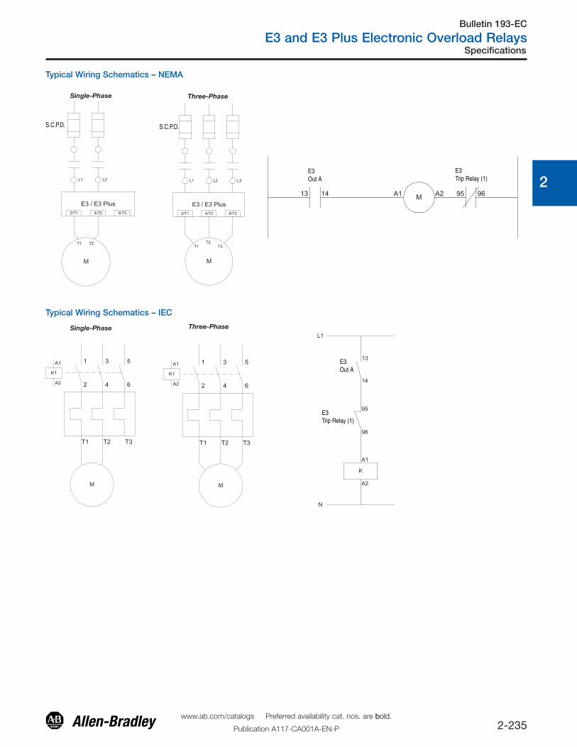
Typical Wiring Schematics – NEMA
S.C.P.D. S.C.P.D.
E3Out A
E3Trip Relay (1)
Single-Phase Three-Phase
Typical Wiring Schematics – IEC
E3Out A
E3Trip Relay (1)
Single-Phase Three-Phase
www.ab.com/catalogs Preferred availability cat. nos. are bbold.
Publication A117-CA001A-EN-P
Bulletin 193-EC
E3 and E3 Plus Electronic Overload Relays
2-236
0
1
2
3
4
5
6
7
8
9
10
11
12
13
Specifications
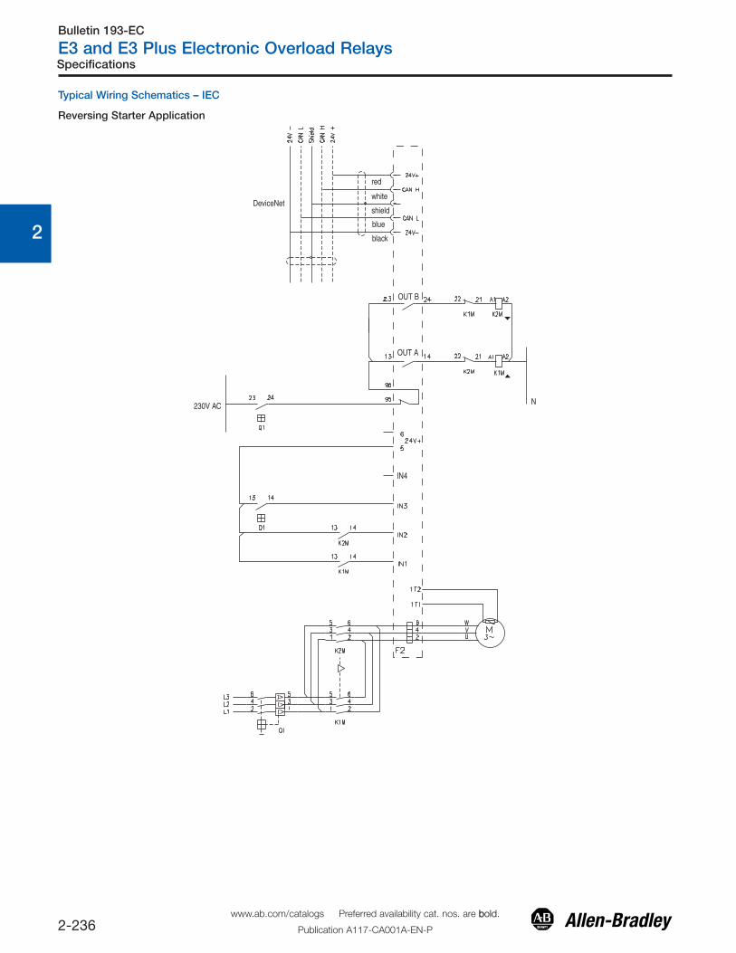
Typical Wiring Schematics – IEC
Reversing Starter Application
DeviceNetwhite
shield
blue
black
red
OUT B
OUT A
N
IN4
230V AC
www.ab.com/catalogs Preferred availability cat. nos. are bbold.
Publication A117-CA001A-EN-P
Bulletin 193-EC
E3 and E3 Plus Electronic Overload Relays
2-237
0
1
2
3
4
5
6
7
8
9
10
11
12
13
Approximate Dimensions
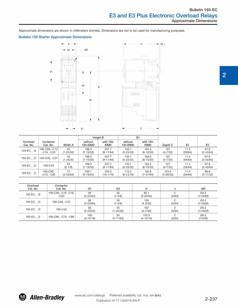
Approximate dimensions are shown in millimeters (inches). Dimensions are not to be used for manufacturing purposes.
Bulletin 109 Starter Approximate Dimensions
C
H J
D1
E2B
B1
E1
D2 øD
A
OverloadCat. No.
ContactorCat. No. Width A
Height B B1
Depth C E1 E2without
193-EIMDwith 193-
EIMDwithout
193-EIMDwith 193-
EIMD
193-EC_ _B 100-C09, -C12-C16, -C23
45(1-25/32)
188.3(7-13/32)
207.7(8-11/64)
145.1(5-23/32)
164.5(6-15/32)
107(4-7/32)
11.4(29/64)
67.9(2-43/64)
193-EC_ _D 100-C30, -C37 45(1-25/32
188.3(7-13/32)
207.7(8-11/64)
145.1(5-23/32)
164.5(6-15/32)
107(4-7/32)
11.4(29/64)
67.9(2-43/64)
193-EC_ _D 100-C43 54(2-1/8)
188.3(7-13/32)
207.7(8-11/64)
145.1(5-23/32)
164.5(6-15/32)
107(4-7/32)
11.4(29/64)
67.9(2-43/64)
193-EC_ _E 100-C60, -C72, -C85
72(2-53/64)
236.1(9-19/64)
255.5(10-1/16)
173.2(6-13/16)
192.6(7-37/64)
124.6(4-29/32)
11.4(29/64)
89.8(3-17/32)
OverloadCat. No.
ContactorCat. No. D1 D2 H J ØD
193-EC_ _B 100-C09, -C12 -C16,-C23
60(2-23/64)
35(1-3/8)
85.1(3-23/64)
2(5/64)
Ø4.2(11/64Ø)
193-EC_ _D 100-C30, -C37 60(2-23/64)
35(1-3/8)
104(4-3/32)
2(5/64)
Ø4.2(11/64Ø)
193-EC_ _D 100-C43 60(2-23/64)
45(1-25/32)
107(4-7/32)
2(5/64)
Ø4.2(11/64Ø)
193-EC_ _E 100-C60, -C72, -C85 100(3-15/16)
55(2-11/64)
125.5(4-15/16)
2(5/64)
Ø5.5(7/32Ø)
www.ab.com/catalogs Preferred availability cat. nos. are bbold.
Publication A117-CA001A-EN-P

Bulletin 193-EC
E3 and E3 Plus Electronic Overload Relays
2-238
0
1
2
3
4
5
6
7
8
9
10
11
12
13
Approximate Dimensions
OverloadCat. No.
ContactorCat. No. A
Height B
B1 Depth C D E1 E2
withoutTerminalCovers
with TerminalCovers
193-EC_ _F
100-D95100-D110
120(4.72)
336.3(13.24)
418(16.45)
311.8(12.27)
175.1(6.89)
156(5.14)
11.4(0.45)
216.1(8.51)
100-D140100-D182
120(4.72)
339.8(13.38)
418(16.45)
317.8(12.50)
175.1(6.89)
156(5.14)
11.4(0.45)
216.1(8.51)
193-EC_ _G
100-D210100-D250100-D300100-D420
155(6.10)
385.8(15.19)
487.4(19.19)
360.8(14.2)
198.9(7.83)
180(7.09)
11.4(0.45)
255(10.04)
193-EC_ _H 100-D630100-D850
255(10.04)
552(21.73)
915(36.02)
508(20)
291.7(11.49)
270.7(10.66)
11.4(0.45)
373.9(14.72)
OverloadCat. No.
ContactorCat. No. F G H J K L M
193-EC_ _F
100-D95100-D110
12.5(0.49)
100(3.94)
145(5.71)
135(5.31)
22.3(0.88)
180.9(7.12)
8 - 5.6(8 - 0.22)
100-D140100-D182
16(0.63)
100(3.94)
145(5.71)
135(5.31)
22.3(0.88)
180.9(7.12)
8 - 5.6(8 - 0.22)
193-EC_ _G
100-D210100-D250100-D300100-D420
21(0.83)
130(5.12)
180(7.09)
140(5.51)
23.5(0.93)
204.7(8.06)
8 - 6.5(8 - 0.26)
193-EC_ _H 100-D630100-D850
52.5(2.07)
226(8.90)
230(9.06)
108(4.25)
109(4.29)
297.5(11.71)
8 - 13(8 - 0.51)
Approximate dimensions are shown in millimeters (inches). Dimensions are not to be used for manufacturing purposes.
Bulletin 109 Starter Approximate Dimensions, Continued
www.ab.com/catalogs Preferred availability cat. nos. are bbold.
Publication A117-CA001A-EN-P
Bulletin 193-EC
E3 and E3 Plus Electronic Overload Relays
2-239
0
1
2
3
4
5
6
7
8
9
10
11
12
13
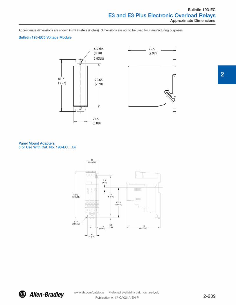
Approximate Dimensions
Approximate dimensions are shown in millimeters (inches). Dimensions are not to be used for manufacturing purposes.
Bulletin 193-EC5 Voltage Module
Panel Mount Adapters(For Use With Cat. No. 193-EC_ _B)
45(1-25/32)
159.3(6-17/64)
7.3(9/32)
135(5-5/16)
6.1(1/4)
100.5(3-31/32)
ø 4.4(11/64 ø)
11.4(29/64)
30(1-3/16)
115(4-17/32)
2 HOLES
75.5(2.97)
22.5(0.89)
70.65(2.78)
4.5 dia.(0.18)
81.7(3.22)
www.ab.com/catalogs Preferred availability cat. nos. are bbold.
Publication A117-CA001A-EN-P
Bulletin 193-EC
E3 and E3 Plus Electronic Overload Relays
2-240
0
1
2
3
4
5
6
7
8
9
10
11
12
13
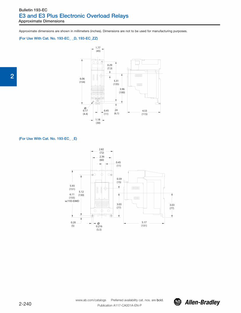
Approximate Dimensions
ø
1.77 (45)
6.06(154)
0.29(7.3)
5.31(135)
3.96(100)
4.53(115)
24(6.1)
0.45(11)
1.18 (30)
0.17(4.4)
(For Use With Cat. No. 193-EC_ _E)
ø
2.82 (72)2.36(60)
0.45 (11)
0.59(15)
3.03(77)
3.03(77)
5.17(131)
5.12(130)
0.20 (5)
5.93(151)
6.11 (155)w/193-EIMD
0.216 (5.5)
(For Use With Cat. No. 193-EC_ _D, 193-EC_ZZ)
Approximate dimensions are shown in millimeters (inches). Dimensions are not to be used for manufacturing purposes.
www.ab.com/catalogs Preferred availability cat. nos. are bbold.
Publication A117-CA001A-EN-P