e3.topology - equipment placement and harness optimization
TRANSCRIPT
Introduction
Zuken’s E³.series is used for documenting and detailing electrical and fluid design projects. Its flexibility supports the entire process from definition and design, through manufacturing and maintenance. Its unique object-oriented architecture ensures all stages of the design are fully synchronized.
E3.topology takes logical designs into the physical world. Topology sheets created at any scale are added to the overall E3.series project. Sheets can represent chassis or plant layouts and installation spaces such as the dashboard or equipment are added to the sheets. The connections between these installation spaces represent harness routes or cable runs. Alternate views of logical devices held in the same project are placed into the relevant installation spaces.
As this process continues, signal logic and wiring information from the schematic is seen automatically in the topology view and the cables start to be automatically defined. Inline devices are easily added and alternate harness configurations can be tested quickly. Reports detail the harnesses, including cost and weight estimates.
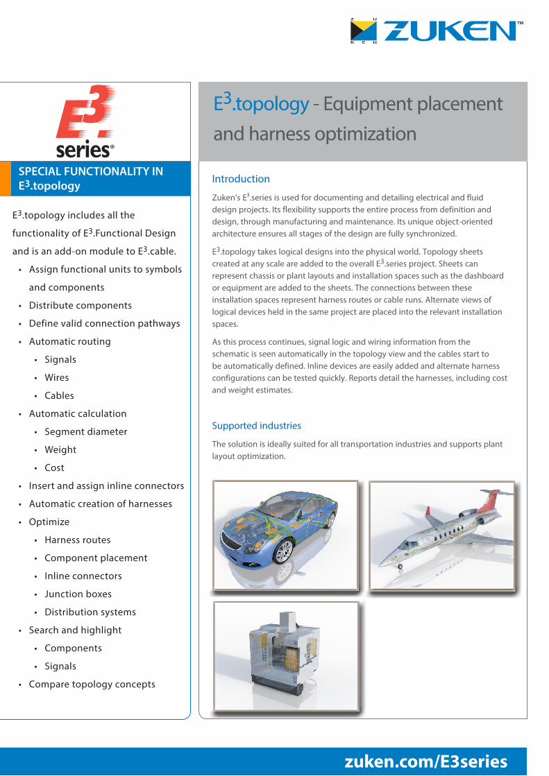
Supported industries
The solution is ideally suited for all transportation industries and supports plant layout optimization.
®
E3.topology - Equipment placement and harness optimization
E3.topology includes all the
functionality of E3.Functional Design
and is an add-on module to E3.cable.
• Assign functional units to symbols
and components
• Distribute components
• Define valid connection pathways
• Automatic routing
• Signals
• Wires
• Cables
• Automatic calculation
• Segment diameter
• Weight
• Cost
• Insert and assign inline connectors
• Automatic creation of harnesses
• Optimize
• Harness routes
• Component placement
• Inline connectors
• Junction boxes
• Distribution systems
• Search and highlight
• Components
• Signals
• Compare topology concepts
™
zuken.com/E3series
SPECIAL FUNCTIONALITY IN E3.topology
Concept design
E³.topology supports the developer from their first sketches to the complete schematic drawing. The vehicle or plant layout is outlined on scaled sheets and the possible installation spaces are defined, then valid connection pathways between installation spaces are created. In parallel, and within the same design space, engineers develop the control schematics.
Harness optimization
The logical components from the schematic are placed in the installation spaces using ‘drag and drop’. E³.topology routes all wires and cables through valid pathways enabling the length, weight and diameter of the individual segments to be calculated automatically. The different harnesses are then evaluated using reports and a rough cost estimate is provided. By moving components to different installation spaces new harness concepts are generated and can be compared to previous options.
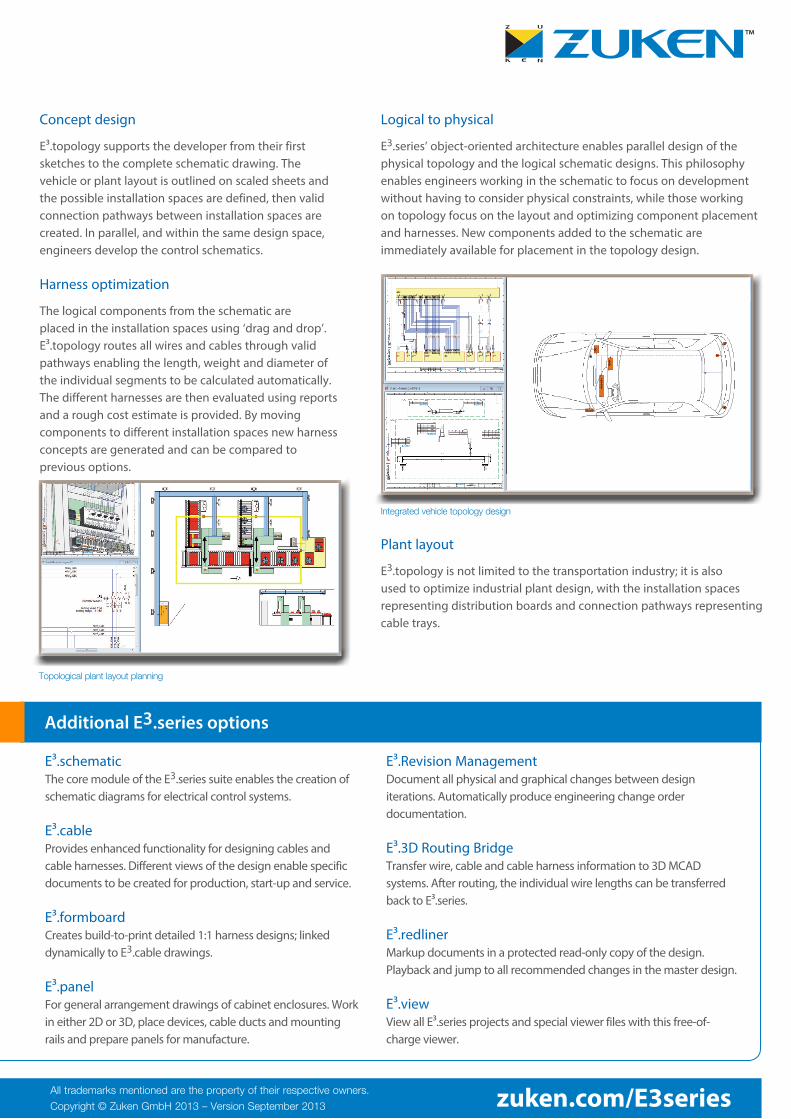
Logical to physical
E3.series’ object-oriented architecture enables parallel design of the physical topology and the logical schematic designs. This philosophy enables engineers working in the schematic to focus on development without having to consider physical constraints, while those working on topology focus on the layout and optimizing component placement and harnesses. New components added to the schematic are immediately available for placement in the topology design.
Plant layout
E3.topology is not limited to the transportation industry; it is also used to optimize industrial plant design, with the installation spaces representing distribution boards and connection pathways representing cable trays.
Topological plant layout planning
™
All trademarks mentioned are the property of their respective owners.
Copyright © Zuken GmbH 2013 – Version September 2013 zuken.com/E3series
E³.schematic The core module of the E3.series suite enables the creation of schematic diagrams for electrical control systems.
E³.cable Provides enhanced functionality for designing cables and cable harnesses. Different views of the design enable specific documents to be created for production, start-up and service.
E³.formboard Creates build-to-print detailed 1:1 harness designs; linked dynamically to E3.cable drawings.
E³.panel For general arrangement drawings of cabinet enclosures. Work in either 2D or 3D, place devices, cable ducts and mounting rails and prepare panels for manufacture.
Additional E3.series options
E³.Revision Management Document all physical and graphical changes between design iterations. Automatically produce engineering change order documentation.
E³.3D Routing Bridge Transfer wire, cable and cable harness information to 3D MCAD systems. After routing, the individual wire lengths can be transferred back to E³.series.
E³.redliner Markup documents in a protected read-only copy of the design. Playback and jump to all recommended changes in the master design.
E³.view View all E³.series projects and special viewer files with this free-of-charge viewer.
Integrated vehicle topology design