e7n and e5n devicenet slave digisolver - autotech … and e5n devicenet slave digisolver (rsnetworx...
TRANSCRIPT

E7N and E5NDeviceNet Slave DigiSolver
(RSNetWorx™ Version)
Instruction & Operation Manual
MAN-E7DEV-001REV 00 12/28/99
Sales and Marketing343 St. Paul Blvd.
Carol Stream, IL 60188Tel: (630)668-3900
FAX: (630)668-4676
Factory Customer Service/Order Entry4140 Utica Ridge Rd.Bettendorf, IA 52722
Tel: (319)359-7501(800)711-5109
FAX: (319)359-9094
Application Hotline1 (800) TEC-ENGR (832-3647)
Vist our web site at: www.avg.net
The DeviceNet Slave E7N and E5N DigiSolver
Introduction
The DigiSolver, a Digital Resolver
The DeviceNet DigiSolver is a resolver-based encoder, in
which the analog signal produced by a brushless resolver is
transformed to a digital format by a built-in ratiometric
tracking converter. This new concept and the advanced
technology of the DigiSolver, with electronic circuitry, pro-
vides higher accuracy, increased reliability, higher operating
speeds, more flexible counts per turn and a smaller size than
optical encoders.
No Optics, Mil-Grade Resolver
There is no optical coded disc or similar component used in
the DigiSolver. A miniature Mil-Grade resolver produces an
analog position signal and high-grade electronics molded in
epoxy transforms this signal to digital format. The resolver
is a passive transducer, well known for its ruggedness and
performance in hostile industrial environments. The Digi-
Solver combines the ruggedness of a resolver with the reli-
ability of solid-state electronics and is designed to operate
reliably under severe environmental conditions, such as me-
chanical shock, vibrations, temperature and humidity
changes, oil mist, coolants and solvents. No broken discs!
No disc misalignments! No LED aging!
High Resolution in Small Compact Housing
The single-turn DigiSolver provides up to 12 bit Binary,
Gray Code or Decimal in a 2.5-inch diameter size (size 25)
housing.
Single-Turn Operation
The DigiSolver is an absolute encoder, that is, it keeps track
of the exact shaft position even during power outage or
switching off the machine. At power-up, the DigiSolver will
pick up the exact shaft position even if the machine moved
during the power outage. In a single-turn operation, the ma-
chine cycle is completed during one complete revolution of
the transducer shaft.
Field Selectable CW or CCW Operation
The DigiSolver is factory wired for ascending counts with
Counterclockwise shaft rotation. However, the direction of
operation can be easily selected in the field by opening up the
case and simply reversing the DigiSolver input plug. No
wires need to be unsoldered or soldered.
Ratiometric Resolver-to-Digital Converter
The Autotech ratiometric tracking converter is practically
immune to electrical noise, voltage, frequency and tempera-
ture variations.
DeviceNet Connection
The DeviceNet E7N DigiSolver model is enclosed in a size
25 (2.5-inch diameter), NEMA 13 housing and designed for
medium duty applications. It is available as a flange mount
or a servo mount model with a DeviceNet connector at the
end. The E5N model is enclosed in a size 40 (4-inch diame-
ter), NEMA 13 housing and is designed for heavy duty ap-
plications. It is available as a face mount with a DeviceNet
connector at the end.
Variety of Outputs
The DigiSolver is available with Binary, Gray Code, or
Decimal absolute position output formats.
Power Supply
An existing power supply can be used to power the Digi-
Solver, that is, if a programmable controller operates at 24
VDC, an 11-30 VDC DigiSolver model can be connected to
the same power supply, thus cutting down the system cost.
Flexible Programming of Counts Per Turn
The advanced R to D converter used in the DigiSolver has
made it possible to program any number of scaled Binary,
Decimal, or Gray Code counts per revolution. The default
encoding format is set to 10 bit Binary.
DeviceNet Basics
DeviceNet is an open network standard, This means that
users may specify, install, and use various products from a
wide number of suppliers without the need to purchase
special equipment, software, or licensing rights. Thus, the
user can create a system from a variety of vendors, yet
specific to the exact application, mainly using off-the-shelf
parts.
DeviceNet is a low-cost communication link that connects
industrial devices, such as limit switches, photoelectric sen-
sors, proximity sensors, valve manifolds, motor starters,
process sensors, bar code readers, variable frequency drives,
panel displays, and operator interfaces to a common net-
work.
Networking devices eliminates the necessity for expensive
hard wiring, and the attendant testing and maintenance that
goes with it. It also reduces the cost and time needed to wire
and install automation devices, while providing improved
communication between devices, as well as important
device-level diagnostics not easily accessible or available
through hardwired I/O interfaces.
MAN-E7DEV-001 Rev 00 12/28/99 DeviceNet Slave E7N and E5N DigiSolver 1

Functional Description of the DigiSolver LED
The bi-color (green/red) LED provides limited device and
communication status. The table below provides a descrip-
tion of the different LED states and their indications. For its
location on the resolver, see page 5.
Electrical Specifications
Input PowerInput Voltage:11�30 VDC
Maximum Input Current:0.15 Amp
Typical Input Current:0.06 Amp @ 24 V
2 DeviceNet Slave E7N and E5N DigiSolver MAN-E7DEV-001 Rev 00 12/28/99
Combined Module/Network Status LED
For this state: LED is: To indicate:
Not powered/Not online OFF
Device is not online.
— the device has not completed theDup_MAC_ID test yet.
— the device may not be powered.
Device OperationalANDOnline, Connected
GREEN
The device is operating in a normal conditionand the device is online with connections inthe established state.
— the device has one or more establishedconnections.
Device Operational AND Online, NotConnected
or
Device Onl ine AND Device needscommissioning
FLASHING GREEN
The Device is operating in a normal condi-tion and the device is online with no connec-tions in the established state.
— the device has passed the Dup_MAC_IDtest, is online, but has no established con-nections to other nodes.
— the device has no established connec-tions.
Critical Fault
or
Critical Link Failure
RED
The device has an unrecoverable fault, mayneed replacing.
Failed communication device. The devicehas detected an error that has rendered it in-capable of communicating on the network(Duplicate MAC ID, or Bus-off).

Installation
Mounting
1. Servo-Mount:
The DigiSolver can be either mounted with traditional
servo-clamps or through the four 4-40 mounting holes on the
face of the resolver.
Zero Reference (±5°) : When flat on shaft lines up with the
screw in the case and the two mounting holes on the face
plate.
2. Flange-Mount:
The DigiSolver can be mounted using the four .218 diameter
mounting holes on the square face plate.
Zero Reference (±5° ): When flat of shaft lines up with the
case screw that is in the middle of a flat side.
Direction of Rotation
The direction of rotation is normally set at the factory for in-
creasing count with CCW rotation (viewed from the shaft
end). This may be changed to increasing count with CW ro-
tation by reversing the internal connector between the re-
solver and decoder electronics. When reassembled, ensure
connector mates securely and wiring is not pinched.
Wiring
1. The shielded interconnecting cable should be routed in its own
conduit and kept separate from other high voltages/high inductance
wiring. The shield drain wire should be connected to earth ground at
both ends of cable.
2. This equipment uses isolated Sig Ref (Com). Failure to assure at
least 100 K Ohm resistance between sig ref and earth ground may
cause erratic output data.
MAN-E7DEV-001 Rev 00 12/28/99 DeviceNet Slave E7N and E5N DigiSolver 3
CAUTION NOTES:1. It is recommended that E7 series DigiSolver be coupled to an
external shaft using a flexible coupling. Autotech recom-
mends ACR series helical couplings. For further information
contact helical products company directly at 805/928-3851.
2. NEMA 13 rating - to maintain the NEMA 13 rating of the Digi-
Solver, the bearing seals must be checked once every six
months and replaced if necessary. Lubricating the bearing
seal periodically prolongs its life.
3. If the DigiSolver is to be axially driven, be sure that the shafts
are aligned. if misaligned, it can destroy the DigiSolver bear-
ing.
4. TheDigiSolvers must be returned to the factory for repair. DO
NOT ATTEMPT TO REPAIR the Electronic Module in the
field; THIS WILL VOID ALL WARRANTIES.
Direction of Rotation Vs Increasing Count Adjustment
Changing connector will
produce a 90° position
offset
CAUTION: Check the cable wiring before applying
power to the DigiSolver
Zero Reference
Decoder ElectronicsResolver
1. Separate Connector
2. Rotate One End
3. Re-Mate Connector
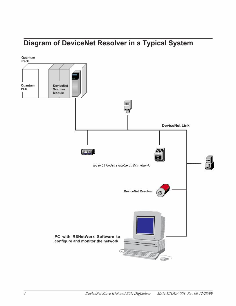
Diagram of DeviceNet Resolver in a Typical System
4 DeviceNet Slave E7N and E5N DigiSolver MAN-E7DEV-001 Rev 00 12/28/99
DeviceNet Link
PC with RSNetWorx Software toconfigure and monitor the network
DeviceNet Resolver
QuantumPLC
(up to 63 Nodes available on this network)
QuantumRack
DeviceNetScannerModule

MAN-E7DEV-001 Rev 00 12/28/99 DeviceNet Slave E7N and E5N DigiSolver 5
DeviceNet Resolver Connector End
with Cover PlateDeviceNet Resolver Connector End
without Cover Plate
Cover Plate **1 of 3 Acorn Nuts for Mount-ing cover plate to posts
Combined Module /Network Status (MNS)LED *
Node Address(NA) DIP Switches1 – 6
DIP Switches 1– 8
1 of 3 posts formounting coverplate
LED Data Rate (DR) Baud RateDIP Switches 7 and 8
5 Pin Sealed MicroDeviceNet Connector(Male)
4 3
5
1 2
Connector Pin Out
1 Drain Bare
2 V+ Red
3 V- Black
4 CAN_H White
5 CAN_L Blue
* LED
For a functional description of the DigiSolver LED, see page 2.
** Cover Plate Removal
1. Remove Cover Plate to access Dip Switches.
2. Using appropriate tool, loosen the 3 acorn nuts, and set aside.
3. Pull plate off posts.
Connector Pins

Outline Dimensions
The outline dimensions of the DigiSolvers are shown in the
following diagrams.
6 DeviceNet Slave E7N and E5N DigiSolver MAN-E7DEV-001 Rev 00 12/28/99
Servo Mount
Flange Mount

1()'32,NF-2 X 30[7.62] DEEP
(4 PLAaS ON 2500[63.500] DIA
:t.OOS[.127])
E5 Face Mount
.625 +.000 [.000][15.875] -.002 [.051)
1.000[2SAOO] :1:.005 [.127]
1.250
[31.750]
MAN-E7DEV-00J Rev 02 10/10/02 DeviceNet Slave E7N and E5N DigiSolver 7
Programming
The DeviceNet Resolver provides basic resolver functional-
ity for control systems equipped with a DeviceNet interface.
Features:
• User definable resolution (12 bit maximum)
• Eight user-definable dwells. Each dwell has 1
ON/OFF setpoint
• Continuously computed RPM
DeviceNet Interface
Supports Polled, Strobed, COS/Cyclic. Produces 4, 5, 6,
or 8 bytes depending on features utilized. Consumes 0 or
1 byte.
Response Time for Resolver:
COS/Cyclic — Value (4 bytes) 2 ms
Value + Cams + RPM (8 bytes) 2.5 ms
Polled — Value (4 bytes) 2 ms
Value + Cams + RPM (8 bytes) 4 ms
Produced Bytes:
Value — This is the current position value after bit reso-
lution and offset have been added. Value uses 4 bytes.
Throughout the manual, Value and Position Value are
equivalent.
Cam — This is a 1 byte value with 1 bit representing the
status of each of the 8 “dwells”. If the bit is “1”, the cur-
rent position is between the Cam Low and Cam High set-
ting.
Example: Cam = 0 x 02 or binary 00000010. This
means that the current position is greater than Cam 2
Low and less than Cam 2 High.
Cams — This is the same as Cam above, but 2 bytes are
produced instead of 1. The most significant byte (MSB)
is reserved and the least significant byte (LSB) functions
as Cam above.
RPM — This is the computed revolutions per minute of
the resolver. RPM uses 2 bytes.
Consumed Bytes:
Auto Zero — This attribute controls the auto-zero fea-
ture of the resolver. Only the least significant bit of the
byte is used. If this bit transitions from 0 to 1, Zero Off-
set is set to a value that results in Position Value being
zero. The only way to restore the user-defined Zero Off-
set value is to cycle power to the resolver, or to re pro-
gram Zero Offset from a configuration tool. The
AutoZero feature may be disabled by setting parameter
21 of the Device parameters. If AutoZero is disabled, the
resolver consumes 0 bytes.
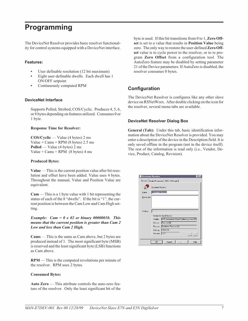
Configuration
The DeviceNet Resolver is configures like any other slave
device on RSNetWorx. After double clicking on the icon for
the resolver, several menu tabs are available.
DeviceNet Resolver Dialog Box
General (Tab): Under this tab, basic identification infor-
mation about the DeviceNet Resolver is provided. You may
enter a description of the device in the Description field. It is
only saved offline in the program (not in the device itself).
The rest of the information is read only (i.e., Vendor, De-
vice, Product, Catalog, Revision).
MAN-E7DEV-001 Rev 00 12/28/99 DeviceNet Slave E7N and E5N DigiSolver 7
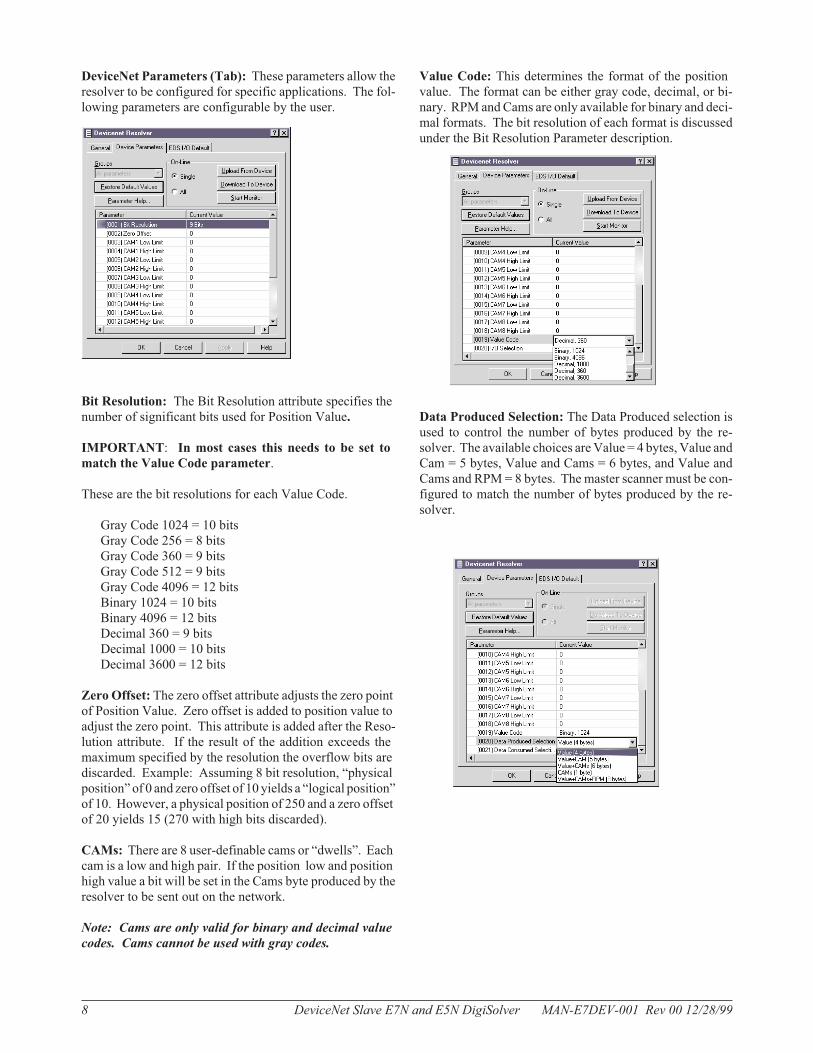
DeviceNet Parameters (Tab): These parameters allow the
resolver to be configured for specific applications. The fol-
lowing parameters are configurable by the user.
Bit Resolution: The Bit Resolution attribute specifies the
number of significant bits used for Position Value.
IMPORTANT: In most cases this needs to be set to
match the Value Code parameter.
These are the bit resolutions for each Value Code.
Gray Code 1024 = 10 bits
Gray Code 256 = 8 bits
Gray Code 360 = 9 bits
Gray Code 512 = 9 bits
Gray Code 4096 = 12 bits
Binary 1024 = 10 bits
Binary 4096 = 12 bits
Decimal 360 = 9 bits
Decimal 1000 = 10 bits
Decimal 3600 = 12 bits
Zero Offset: The zero offset attribute adjusts the zero point
of Position Value. Zero offset is added to position value to
adjust the zero point. This attribute is added after the Reso-
lution attribute. If the result of the addition exceeds the
maximum specified by the resolution the overflow bits are
discarded. Example: Assuming 8 bit resolution, “physical
position” of 0 and zero offset of 10 yields a “logical position”
of 10. However, a physical position of 250 and a zero offset
of 20 yields 15 (270 with high bits discarded).
CAMs: There are 8 user-definable cams or “dwells”. Each
cam is a low and high pair. If the position low and position
high value a bit will be set in the Cams byte produced by the
resolver to be sent out on the network.
Note: Cams are only valid for binary and decimal value
codes. Cams cannot be used with gray codes.
Value Code: This determines the format of the position
value. The format can be either gray code, decimal, or bi-
nary. RPM and Cams are only available for binary and deci-
mal formats. The bit resolution of each format is discussed
under the Bit Resolution Parameter description.
Data Produced Selection: The Data Produced selection is
used to control the number of bytes produced by the re-
solver. The available choices are Value = 4 bytes, Value and
Cam = 5 bytes, Value and Cams = 6 bytes, and Value and
Cams and RPM = 8 bytes. The master scanner must be con-
figured to match the number of bytes produced by the re-
solver.
8 DeviceNet Slave E7N and E5N DigiSolver MAN-E7DEV-001 Rev 00 12/28/99
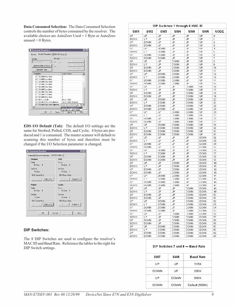
Data Consumed Selection: The Data Consumed Selection
controls the number of bytes consumed by the resolver. The
available choices are AutoZero Used = 1 Byte or AutoZero
unused = 0 Bytes.
EDS I/O Default (Tab): The default I/O settings are the
same for Strobed, Polled, COS, and Cyclic. 4 bytes are pro-
duced and 1 is consumed. The master scanner will default to
scanning this number of bytes and therefore must be
changed if the I/O Selection parameter is changed.
DIP Switches:
The 8 DIP Switches are used to configure the resolver’s
MAC ID and Baud Rate. Reference the tables to the right for
DIP Switch settings.
MAN-E7DEV-001 Rev 00 12/28/99 DeviceNet Slave E7N and E5N DigiSolver 9
DIP Switches 1 through 6 MAC ID
SW1 SW2 SW3 SW4 SW5 SW6 NODE
UP UP UP UP UP UP 0
DOWN UP UP UP UP UP 1
UP DOWN UP UP UP UP 2
DOWN DOWN UP UP UP UP 3
UP UP DOWN UP UP UP 4
DOWN UP DOWN UP UP UP 5
UP DOWN DOWN UP UP UP 6
DOWN DOWN DOWN UP UP UP 7
UP UP UP DOWN UP UP 8
DOWN UP UP DOWN UP UP 9
UP DOWN UP DOWN UP UP 10
DOWN DOWN UP DOWN UP UP 11
UP UP DOWN DOWN UP UP 12
DOWN UP DOWN DOWN UP UP 13
UP DOWN DOWN DOWN UP UP 14
DOWN DOWN DOWN DOWN UP UP 15
UP UP UP UP DOWN UP 16
DOWN UP UP UP DOWN UP 17
UP DOWN UP UP DOWN UP 18
DOWN DOWN UP UP DOWN UP 19
UP UP DOWN UP DOWN UP 20
DOWN UP DOWN UP DOWN UP 21
UP DOWN DOWN UP DOWN UP 22
DOWN DOWN DOWN UP DOWN UP 23
UP UP UP DOWN DOWN UP 24
DOWN UP UP DOWN DOWN UP 25
UP DOWN UP DOWN DOWN UP 26
DOWN DOWN UP DOWN DOWN UP 27
UP UP DOWN DOWN DOWN UP 28
DOWN UP DOWN DOWN DOWN UP 29
UP DOWN DOWN DOWN DOWN UP 30
DOWN DOWN DOWN DOWN DOWN UP 31
UP UP UP UP UP DOWN 32
DOWN UP UP UP UP DOWN 33
UP DOWN UP UP UP DOWN 34
DOWN DOWN UP UP UP DOWN 35
UP UP DOWN UP UP DOWN 36
DOWN UP DOWN UP UP DOWN 37
UP DOWN DOWN UP UP DOWN 38
DOWN DOWN DOWN UP UP DOWN 39
UP UP UP DOWN UP DOWN 40
DOWN UP UP DOWN UP DOWN 41
UP DOWN UP DOWN UP DOWN 42
DOWN DOWN UP DOWN UP DOWN 43
UP UP DOWN DOWN UP DOWN 44
DOWN UP DOWN DOWN UP DOWN 45
UP DOWN DOWN DOWN UP DOWN 46
DOWN DOWN DOWN DOWN UP DOWN 47
UP UP UP UP DOWN DOWN 48
DOWN UP UP UP DOWN DOWN 49
UP DOWN UP UP DOWN DOWN 50
DOWN DOWN UP UP DOWN DOWN 51
UP UP DOWN UP DOWN DOWN 52
DOWN UP DOWN UP DOWN DOWN 53
UP DOWN DOWN UP DOWN DOWN 54
DOWN DOWN DOWN UP DOWN DOWN 55
UP UP UP DOWN DOWN DOWN 56
DOWN UP UP DOWN DOWN DOWN 57
UP DOWN UP DOWN DOWN DOWN 58
DOWN DOWN UP DOWN DOWN DOWN 59
UP UP DOWN DOWN DOWN DOWN 60
DOWN UP DOWN DOWN DOWN DOWN 61
UP DOWN DOWN DOWN DOWN DOWN 62
DOWN DOWN DOWN DOWN DOWN DOWN 63
DIP Switches 7 and 8 � Baud Rate
SW7 SW8 Baud Rate
UP UP 125K
DOWN UP 250K
UP DOWN 500K
DOWN DOWN Default (500K)
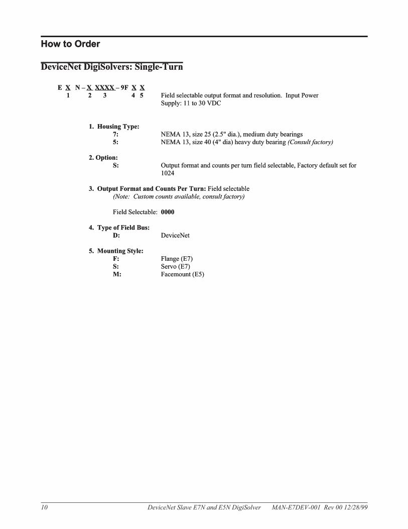
How to Order
DeviceNet DigiSolvers: Single-Turn
E X N – X XXXX – 9F X X
1 2 3 4 5 Field selectable output format and resolution. Input Power
Supply: 11 to 30 VDC
1. Housing Type:
7: NEMA 13, size 25 (2.5" dia.), medium duty bearings
5: NEMA 13, size 40 (4" dia) heavy duty bearing (Consult factory)
2. Option:
S: Output format and counts per turn field selectable, Factory default set for
1024
3. Output Format and Counts Per Turn: Field selectable
(Note: Custom counts available, consult factory)
Field Selectable: 0000
4. Type of Field Bus:
D: DeviceNet
5. Mounting Style:
F: Flange (E7)
S: Servo (E7)
M: Facemount (E5)
10 DeviceNet Slave E7N and E5N DigiSolver MAN-E7DEV-001 Rev 00 12/28/99
How to Order
DeviceNet DigiSolvers: Single-Turn
E X N – X XXXX – 9F X X
1 2 3 4 5 Field selectable output format and resolution. Input Power
Supply: 11 to 30 VDC
1. Housing Type:
7: NEMA 13, size 25 (2.5" dia.), medium duty bearings
5: NEMA 13, size 40 (4" dia) heavy duty bearing (Consult factory)
2. Option:
S: Output format and counts per turn field selectable, Factory default set for
1024
3. Output Format and Counts Per Turn: Field selectable
(Note: Custom counts available, consult factory)
Field Selectable: 0000
4. Type of Field Bus:
D: DeviceNet
5. Mounting Style:
F: Flange (E7)
S: Servo (E7)
M: Facemount (E5)
MAN-E7DEV-001 Rev 00 12/28/99 DeviceNet Slave E7N and E5N DigiSolver 11
The information in this book has been carefullychecked and is believed to be accurate; however, noresponsibility is assumed for inaccuracies. AutotechControls reserves the right to make changes withoutfurther notice to any products herein to improve reliabil-ity, function or design. Autotech Controls does not as-sume any liability arising out of application or use of anyproduct described herein
Autotech Controls does not recommend the use of itsproducts in applications wherein a failure or malfunc-tion of the unit may directly threaten life or cause hu-man injury. The user of Autotech Controls' productsassumes all risks of such use and indemnifies AutotechControls against all damages.
© Copyright 1999 by Autotech Controls, Limited Part-nership. All rights reserved.
WARRANTY
Autotech Controls warrant their products to be free from defects in materials or workmanship for a period of one year from the date of shipment, pro-vided the products have been installed and used under proper conditions. The defective products must be returned to the factory freight prepaid andmust be accompanied by a Return Material Authorization (RMA) number. The Company's liability under this limited warranty shall extend only to therepair or replacement of a defective product, at TheCompany's option. TheCompany disclaims all liability for any affirmation, promise or representa-tion with respect to the products.
The customer agrees to hold Autotech Controls harmless from, defend, and indemnify Autotech Controls against damages, claims, and expensesarising out of subsequent sales of Autotech Controls' products or products containing components manufactured by Autotech Controls and basedupon personal injuries, deaths, property damage, lost profits, and other matters which Buyer, its employees, or subcontractors are or may be to anyextent liable, including without limitation penalties imposed by the Consumer Product Safety Act (P.L. 92-573) and liability imposed upon any personpursuant to the Magnuson-Moss Warranty Act (p.l. 93-637), as now in effect or as amended hereafter.
Nowarranties expressed or implied are created with respect to TheCompany's products except those expressly contained herein. The customer ac-knowledges the disclaimers and limitations contained and relies on no other warranties or affirmations.
CAUTIONAutotech Controls' products are carefully engineered and rigorously tested to provide many years of re-liable operation. However any solid-state device may fail or malfunction sometime.The user must en-sure that his system design has built-in redundancies if Autotech Controls' product is being used inapplications where a failure or malfunction of the unit may directly threaten life or cause human injury.The system should be so designed that a single failure or malfunction does not create an unsafe condi-tion. Regularly scheduled inspections, at least once a week, should be made to verify that the redundantcircuits are fully functional. All faults should be immediately corrected by repair or replacement of thefaulty unit. In addition, the user may have to comply with OSHA, ANSI, state or local standards of safety.The user of Autotech Controls' products assumes all risks of such use and indemnifies Autotech Con-trols against any damages.
MANUFACTURING4140 Utica Ridge Rd. � Bettendorf, IA 52722-1327
CUSTOMER SERVICE / SALES / MARKETING / ADMINISTRATION343 St. Paul Blvd. � Carol Stream, IL 60188
Application HOTLINE: 1-800-TEC-ENGR (832-3647) • Phone: 630-668-3900 • Fax: 630-668-4676
DeviceNet™ Resolver