e91 embedded system - swarthmore college · why embedded systems? ... s a ways rue, so oop orever....
TRANSCRIPT

E91Embedded System
Intro
Why embedded systems?Why embedded systems?
• Big bang-for-the-buck by adding Big bang for the buck by adding some intelligence to systems.
• Embedded Systems are ubiquitous• Embedded Systems are ubiquitous.• Embedded Systems more common
i d d das prices drop, and power decreases.

Which Embedded System?Which Embedded System?• We will use Texas Instruments MSP-430+ very popular (#2 next to microchip)+ 16 bits (instead of 8)
l + low power+ clean architecture+ low cost (free) development toolslow cost (free) development tools- relatively low speed/capacity (i.e., no video
or fancy audio)low level tools (compared to Stamp - low level tools (compared to Stamp, Arduino…)
- 16 bits (instead of 32)

Course overviewCourse overview• Mix of hardware and software• Mostly C, some assembly• Lots of information, less conceptual than many
courses.• Two hardware kits, EZ430 and the 430 Two hardware kits, EZ430 and the 430
Experimenter’s Board• About 2 hours of lecture per week.• More hours in lab – writeups will be short• More hours in lab – writeups will be short.• In lab you will need to become familiar with a
broad set of documentation. I will try to keep a complete list on website Let me know if you find complete list on website. Let me know if you find good documents I have not listed.
• You will need to be more self-reliant than in many courses (though I am always ready to help)courses (though I am always ready to help).
• Maybe some assignments.

Policy on working together :Policy on working together :• Lab groups should be 2 (preferably) or 3 students.• We expect labs to be done as a group with your lab• We expect labs to be done as a group with your lab partners. You may discuss your lab with other groups, but you may not copy anything from their g p , y y py y greports. Each group will submit a single report (with all members of the group listed).

TodayToday
• Brief overview ofBrief overview ofo logico numberso numbersoC
MSP430 digital I/OoMSP430 digital I/O
Today’s lecture will be very densely packed so you can start on the lab. We will come back and repeat some of the material in more depth as needed.

Brief Review of LogicBrief Review of Logic• In this class we will deal with logical In this class we will deal with logical
circuits (i.e., inputs are either true (logical 1, for us this is 3.3V) or false ( g , )(logical 0, for us this is 0V). In class you will learn why this is useful, for
t itnow, accept it.• To deal with these signal levels we
d l i l f f develop a special form of mathematics, Boolean algebra.
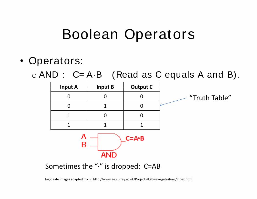
Boolean OperatorsBoolean Operators
• Operators:Operators:oAND : C=A·B (Read as C equals A and B).
Input A Input B Output CInput A Input B Output C
0 0 0
0 1 0“Truth Table”
1 0 0
1 1 1
logic gate images adapted from: http://www.ee.surrey.ac.uk/Projects/Labview/gatesfunc/index.html
Sometimes the “∙” is dropped: C=AB

More logic…A B D
0 0 0
0 1 10 1 1
1 0 1
1 1 1
A F
0 1
1 0
A B HA B H
0 0 1
0 1 0
1 0 0
1 1 0

… and even more.A B G
0 0 1
0 1 10 1 1
1 0 1
1 1 0
A B J
0 0 00 0 0
0 1 1
1 0 1
1 1 0eXclusive OR
Note:O i h i biXOR with 1 inverts bit, XOR with 0 passes bit.

Number SystemsDecimal Binary Hex
0 0000 0
1 0001 1
2 0010 2Binary: 000011012 = 1·23 + 1·22 + 0·21 + 1·20 =
8 + 4 + 1 = 13
2 0010 2
3 0011 3
4 0100 4
5 0101 5
Hex: 001010102 = 2A16 = 0x2A = 2·161 + 10·160 = 32 + 10 = 42
(check 1·25 + 1·23 + 2·21 = 32 + 8 + 2 = 42)
6 0110 6
7 0111 7
8 1000 8
9 1001 9
8 bits = 1 byte0000 00002 → 1111 111120x00 → 0xff
9 1001 9
10 1010 A
11 1011 B
12 1100 C0x00 → 0xff0 → 28-1=255 (or -128 → 127 (-(27) → 27-1)))
16 bit 2 b t 1 d
13 1101 D
14 1110 E
15 1111 F
16 bits = 2 bytes = 1 word0000 0000 0000 00002 → 1111 1111 1111 111120x0000 → 0xffff
16 ( ( 15 15 ))0 → 216-1=65535 (or -32768 → 32767 (-(215) → 215-1)))
4 bits = 1 nybble (0 → 24-1=15)
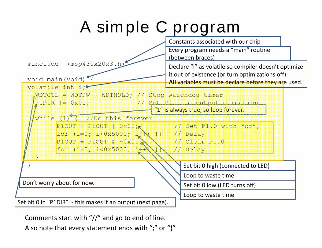
A simple C programConstants associated with our chip
#include <msp430x20x3.h>
i i i
Every program needs a “main” routine (between braces)Declare “i” as volatile so compiler doesn’t optimize it out of existence (or turn optimizations off).
void main(void) {volatile int i;WDTCTL = WDTPW + WDTHOLD; // Stop watchdog timerP1DIR |= 0x01; // Set P1.0 to output direction
“1” i l t l f
( p )All variables must be declare before they are used.
while (1) { //Do this foreverP1OUT = P1OUT | 0x01; // Set P1.0 with “or”, |for (i=0; i<0x5000; i++) {} // Delay1O 1O 0 01 // Cl 1 0
“1” is always true, so loop forever.
P1OUT = P1OUT & ~0x01; // Clear P1.0for (i=0; i<0x5000; i++) {} // Delay
}} Set bit 0 high (connected to LED)
Don’t worry about for now.
Set bit 0 in “P1DIR” this makes it an output (next page)
Loop to waste timeSet bit 0 low (LED turns off)Loop to waste time
Set bit 0 in P1DIR ‐ this makes it an output (next page).
Also note that every statement ends with “;” or “}”Comments start with “//” and go to end of line.

A typical I/O pinAnalog switch
SD16AE=0, by default
Inverted input
Electronically controlled digital switch
P1REN=0, by default 2‐1 Mux (multiplexer)
Tri‐State Output
P1SEL=0, by defaultSchmitt trigger (hysteresis)gg ( y )
Transparent latch

Effect of P1DIR
00
0 0, switch is open
P1DIR=0P1DIR=1
0
Hi‐Z VinP1OUT
0P1DIR
1 10
0 P1OUTHi‐Z
0
VinP1OUT
P1OUT
Latch is disabled

Variant 1 (more readable)Variant 1 (more readable)#include <msp430x20x3.h>#define LED 0x01
Give constants meaningful namesvoid main(void) {volatile int i;WDTCTL = WDTPW + WDTHOLD; // Stop watchdog timer1 | // 1 0 ( bi )
Give constants meaningful names.
P1DIR |= LED; // Set P1.0 (LED bit) to output
while (1) { //Do this foreverP1OUT |= LED; // Turn on LEDf (i 0 i 0 5000 i ) {} // lfor (i=0; i<0x5000; i++) {} // DelayP1OUT &= ~0x01; // Turn off LEDfor (i=0; i<0x5000; i++) {} // Delay
}}}
i lEquivalent to: P1OUT = P1OUT | LED;

Variant 2 (macros)Variant 2 (macros)#include <msp430x20x3.h>#define LED 0x01# i#define SETBIT(p,b) (p |= (b))#define CLRBIT(p,b) (p &= ~(b))
void main(void) {l il i i
Use Macros sparingly, but they can make code look much cleaner (see below)
volatile int i;WDTCTL = WDTPW + WDTHOLD; // Stop watchdog timerP1DIR |= LED; // Set P1.0 to output direction
hil (1) { // hi fwhile (1) { //Do this foreverSETBIT(P1OUT,LED); // Set P1.0for (i=0; i<0x5000; i++) {} // Delay CLRBIT(P1OUT,LED); // Clear P1.0f (i 0 i 0 5000 i ) {} // D l }for (i=0; i<0x5000; i++) {} // Delay }
}
Expands to: (P1OUT |= (0x01))Expands to: (P1OUT | (0x01))Note “;” must be added.

Variant 3 (shorter)Variant 3 (shorter)#include <msp430x20x3.h>#define LED 0x01# i#define SETBIT(p,b) (p |= (b))#define CLRBIT(p,b) (p &= ~(b))#define TGLBIT(p,b) (p ^= (b))
id i ( id) {void main(void) {volatile int i;WDTCTL = WDTPW + WDTHOLD; // Stop watchdog timerP1DIR |= 0x01; // Set P1.0 to output direction
New macro to toggle (xor) bit
while (1) { //Do this foreverTGLBIT(P1OUT,LED); // Toggle LEDfor (i=0; i<0x5000; i++) {} // Delay
}}}
Loop is half as long as before

C Data Types (that we will use)
Type Size Representation Minimum Maximum(bits)
char, signed char 8 ASCII ‐128 +127
unsigned char, bool 8 ASCII 0 255
int, signed int 16 2s complement ‐32 768 32 767
unsigned int 16 Binary 0 65 535
long signed long 32 2s complement 2 147 483 648 2 147 483 647long, signed long 32 2s complement ‐2 147 483 648 2 147 483 647
unsigned long 32 Binary 0 4 294 967 295
enum 16 2s complement ‐32 768 32 767
float 32 IEEE 32‐bit ±1.175 495e‐38 ±3.40 282 35e+38

C Operators (Arithmetic)
Arithmetic Operator name Syntax
Basic assignment a = b
Addition a + b
Subtraction a ‐ b
Unary plus +a
Unary minus (additive inverse) ‐a
Multiplication a * b
Division a / b
Modulo (remainder) a % b( )
IncrementPrefix ++a
Suffix a++
DecrementPrefix ‐‐a
Suffix a‐‐

More C Operators (Relational, Logical, Bitwise and Compound)(Relational, Logical, Bitwise and Compound)
Relational Operator name SyntaxEqual to a ==bNot equal to a !=b
Logical Operator name SyntaxLogical negation (NOT) !aLogical AND a &&b
Greater than a > bLess than a < bGreater than or equal to a >=bLess than or equal to a <=b
Logical AND a &&bLogical OR a ||b
Compound Operator name SyntaxLess than or equal to a <=b
Bitwise Operator name Syntax
Bitwise NOT ~a
Addition assignment a += b
Subtraction assignment a ‐= b
Multiplication assignment a *= bBitwise NOT aBitwise AND a & bBitwise OR a | bBitwise XOR a ^ b
Multiplication assignment a = b
Division assignment a /= b
Modulo assignment a %= b
Bitwise left shift a <<bBitwise right shift a >>b
Bitwise AND assignment a &= b
Bitwise OR assignment a |= b
Bitwise XOR assignment a ^= b
Bitwise left shift assignment a <<=b
Bitwise right shift assignment a >>=b

More CStatements• a simple statement is a single statement that ends in a “;”• a compound statement is several statements inside braces:
{ simple statement; …simple statement;}}
IndentinggThere are no rules about indenting code, but if you don’t adopt a standard style, your code becomes unreadable.

Even more CEven more CArray definitionint a [100]; //Array elements are a[0] to a[99]. Don’t use a[100]!
if…thenif (<expression>)
<statement>
if then else
<statement><statement> may be a compound statement.
if…then…elseif (<expression>)
<statement1>else
<statement2><statement2>
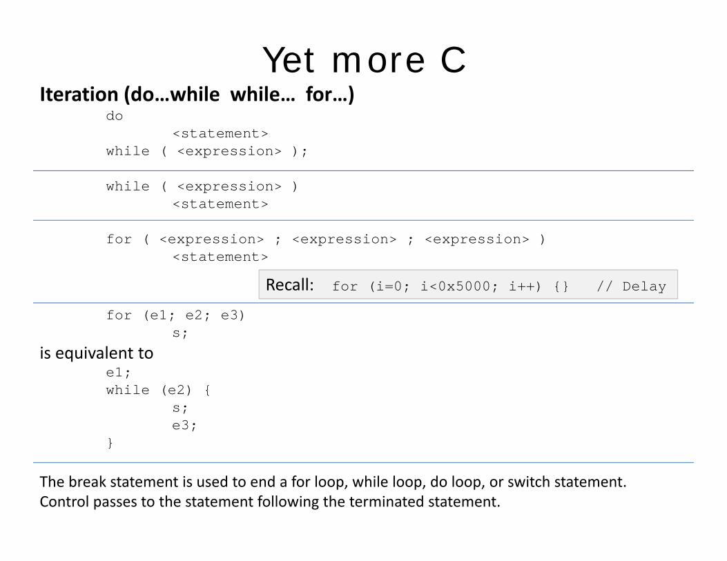
Yet more CIteration (do…while while… for…)( )
do <statement>
while ( <expression> );
while ( <expression> ) <statement>
for ( <expression> ; <expression> ; <expression> ) p p p<statement>
for (e1; e2; e3)
Recall: for (i=0; i<0x5000; i++) {} // Delay
for (e1; e2; e3) s;
is equivalent toe1; hil ( 2) {while (e2) {
s; e3;
}
The break statement is used to end a for loop, while loop, do loop, or switch statement. Control passes to the statement following the terminated statement.

Again with the Ci h ( h i f )switch (one choice of many)
switch (<expression>) { case <label1> :
<statements 1> case <label2> :
<statements 2> break;
default : <statements 3>
}• <expression> is compared against the label, and execution of the associated statements occur (i e if <expression> is equal to <label1> <statements 1> arestatements occur (i.e., if <expression> is equal to <label1>, <statements 1> are exectuted.• No two of the case constants may have the same value. • There may be at most one default label.y• If none of the case labels are equal to the expression in the parentheses following switch, control passes to the default label, or if there is no default label, execution resumes just beyond the entire construct. • Switch statements can "fall through", that is, when one case section has completed its execution, statements will continue to be executed downward until a break; statement is encountered. This is usually not wanted, so be careful

Material taken from:Material taken from:• http://en.wikipedia.org/wiki/C_syntax
htt // iki di / iki/I d t t l• http://en.wikipedia.org/wiki/Indent_style• http://en.wikipedia.org/wiki/Operators_in_C_and_C++• http://focus.ti.com/lit/ug/slau144e/slau144e.pdf• http://focus.ti.com/lit/ds/slas491e/slas491e.pdf• http://focus.ti.com/lit/ug/slau132c/slau132c.pdf