eages proceedings - g. taylor
TRANSCRIPT

A Practical Guide to Building Ekranoplan(WIG) Models
Prepared for the EAGES 2001 International Ground Effect Symposium
Toulouse, France
June 2001
Graham Taylor MBA
Independent Consultant
Commercial and Business Management
102 Garratts Way High
Wycombe Bucks HP13 5XT
England
Tel : +44 (0)1494 461689
Office/fax : +44 (0)1494 510612
145

146

A Practical Guide to Building Ekranoplan (WIG) Models
Graham Taylor
ABSTRACT
During the last 50 years scientists professors and students have written many learned paperswhich explore the complexities of ground effect aerodynamic theory. Although these theories maybe visualised in the minds eye, the underlying objective of such work is to realise the WIG conceptin physical reality. Research facilities around the world have produced some very significant modelsand dramatic prototypes, but the cost of such work can appear off-putting to those without strongfinancial backing. This paper demonstrates how accessible the subject of WIG really is and how,with very few facilities and at very little cost, it is possible to build a working model to explore theWIG phenomenon. The first part of this paper discusses the authors’ experiments, while the secondexplores approaches to making a successful model. As this paper is about the authors’ experiencesit is written in the first person.
ABOUT THE AUTHOR
Graham Taylor has a background in engineering and commercial management, supported byan MBA from Thames Valley University, London in 1995. He has held a variety of positionswithin several industries, including the post of Technical Director of The Royal Institution of NavalArchitects. He has maintained a close interest in the development of high-speed marine vehiclesfor 20 years, and has published several papers on the commercialisation of WIG. Over the yearshe has built a variety of experimental models including hydrofoils, stepped hulls, and hydroskis.He is currently experimenting with a series of radio controlled ekranoplan models (Figure 1). Heis a frequent contributor to model magazines on the subject of high speed marine vehicles.
Figure 1 : Some of the authors experimental WIG models ; MK1, MK2, MK3, & MK4
147

148

Graham Taylor A practical guide to building ekranoplan (WIG) models 149
INTRODUCTION - THE EKRANOPLAN AS A CONCEPT
When Sir Christopher Cockerell teamed up with Mr Latimer-Needham in 1961, he put on thevery feature that holds the hovercraft back - the skirt. The skirt determined that the vehicle hedeveloped would forever be supported by a static cushion rather than a dynamic one. The skirtlimits the hovercraft to a speed of around 80 knots, beyond which it is unfeasible to pressurise thestatic cushion against the dynamic pressure acting on the front of the craft. For higher speed it isbetter to remove the skirt altogether. What we have left is a WIG, a ’dynamic hovercraft’ withoutthe need of a heavy skirt, or lift engines. Stripped down, it is a very simple concept comprisingan aerodynamic hull form, an air propulsor and a rudder. The WIG concept can be demonstratedby skimming a playing card across a table. WIGs main attribute is that it should (according topopular theory) be able to carry significantly more load, and at less power, than a conventionalaircraft. This was the starting point for my experiments in ground effect some 20 years ago.
THE AUTHORS EXPERIMENTS
My first experiments into ground-effect began with a simple Lippisch reverse-delta model (MK1)powered by a model aircraft Cox 049 engine (Figure 2).
The Lippisch configuration was chosen because of its supposed greater inherent stability whenmoving between ’in ground effect’ (IGE) and ’out of ground effect’ (OGE). The models’ operationwas constrained to ground effect by virtue of its low power.
Figure 2 : The MK1 Lippisch style model showing the PAR duct below the propeller
Although little power is required to ’fly’ in ground-effect, one of the major problems with theconcept is that it can take considerably more power to get the craft up to flying speed (especiallyif it has to ’un-stick’ from water first). To help address this, the model featured Power AugmentedRam (PAR) whereby a proportion of the airflow from the propeller was directed under the wingto form a primitive hovercraft air cushion. However, this approach meant that the effective centreof lift moved from 1
2 cord in static cushion mode to approximately 14 cord in OGE mode. Stability
was assisted by a large T tail. The model worked well and was good fun on a cropped grass playingfield, although its directional control was questionable.
150 EAGES Proceedings
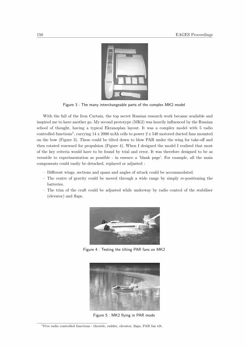
Figure 3 : The many interchangeable parts of the complex MK2 model
With the fall of the Iron Curtain, the top secret Russian research work became available andinspired me to have another go. My second prototype (MK2) was heavily influenced by the Russianschool of thought, having a typical Ekranoplan layout. It was a complex model with 5 radiocontrolled functions1, carrying 14 x 2000 mAh cells to power 2 x 540 motored ducted fans mountedon the bow (Figure 3). These could be tilted down to blow PAR under the wing for take-off andthen rotated rearward for propulsion (Figure 4). When I designed the model I realised that mostof the key criteria would have to be found by trial and error. It was therefore designed to be asversatile to experimentation as possible - in essence a ’blank page’. For example, all the maincomponents could easily be detached, replaced or adjusted :
– Different wings, sections and spans and angles of attack could be accommodated.– The centre of gravity could be moved through a wide range by simply re-positioning the
batteries.– The trim of the craft could be adjusted while underway by radio control of the stabiliser
(elevator) and flaps.
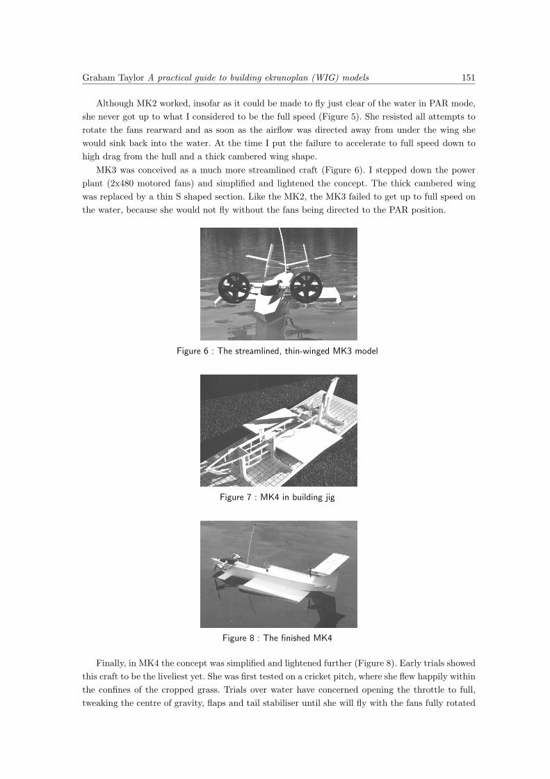
Figure 4 : Testing the tilting PAR fans on MK2
Figure 5 : MK2 flying in PAR mode
1Five radio controlled functions : throttle, rudder, elevator, flaps, PAR fan tilt.
Graham Taylor A practical guide to building ekranoplan (WIG) models 151
Although MK2 worked, insofar as it could be made to fly just clear of the water in PAR mode,she never got up to what I considered to be the full speed (Figure 5). She resisted all attempts torotate the fans rearward and as soon as the airflow was directed away from under the wing shewould sink back into the water. At the time I put the failure to accelerate to full speed down tohigh drag from the hull and a thick cambered wing shape.
MK3 was conceived as a much more streamlined craft (Figure 6). I stepped down the powerplant (2x480 motored fans) and simplified and lightened the concept. The thick cambered wingwas replaced by a thin S shaped section. Like the MK2, the MK3 failed to get up to full speed onthe water, because she would not fly without the fans being directed to the PAR position.
Figure 6 : The streamlined, thin-winged MK3 model
Figure 7 : MK4 in building jig
Figure 8 : The finished MK4
Finally, in MK4 the concept was simplified and lightened further (Figure 8). Early trials showedthis craft to be the liveliest yet. She was first tested on a cricket pitch, where she flew happily withinthe confines of the cropped grass. Trials over water have concerned opening the throttle to full,tweaking the centre of gravity, flaps and tail stabiliser until she will fly with the fans fully rotated

152 EAGES Proceedings
from their PAR position and without ’blowing over’. The difference between PAR and ground-effect flight can be clearly seen : PAR flight leaves a wake on the surface of the water where it hasbeen blown by the fans. In full ground-effect flight, the disturbance behind the boat has virtuallydisappeared (Figures 9-12).
Figures 9-12 : Captured video from early MK4 tests
MK4 will happily zoom up and down a lake at full throttle in straight lines, provided I neverrotate the fans to the PAR position while at speed. To do so results in an immediate back-flip(’blow-over’). Turning at full speed within the confines of my test lake is not possible. Indeed, I runout of lake before full speed is achieved, and stopping the boat can be a problem. She glides for aconsiderable distance between shutting the throttle and contacting the water. Fortunately MK4’sdirectional control at half speed on PAR is exceptional, and she will ’side-slip’ like a hovercraft.

Graham Taylor A practical guide to building ekranoplan (WIG) models 153
Development of the MK4 concept has continued with two further prototypes that explore turningand braking issues (Figure 13). The MK4, MK5 and MK6 craft are part of the ’WhizzyWig’ projectto produce plans, and possibly a kit, for sale to model enthusiasts. As regards the tilting fan PARsystem, I am not convinced that this is really the way forward for full size craft because it placesthe propellers in the vicinity of wave and spray impact, but the amphibious qualities it gives amodel are great fun.
Figure 13 : MK5 with MK6 under construction to test ’Through-Wing’ flaps.
MODEL DESIGN - A PHILOSOPHICAL APPROACH
Before exploring the specifics of model making let me first put model WIGs in context with thedevelopment and commercialisation of full size WIG. Let us consider the three main dimensionsconstraining the design of a commercially successful full size WIG :
1. Maximum Safety
2. Maximum Load Carrying Capability
3. Minimum Capital Cost
Safety concerns the stability of the vehicle, its capability to operate in a seaway, and the survivalof persons in the event of an accident. Load carrying capacity is the most acclaimed feature of theWIG concept, and concerns the payload that earns the revenue. Capital cost is the main componentof costs that a commercial operation of WIG will have to finance from the revenue earned. Note thatneither aerodynamic finesse or fuel economy are included above, both of which can be consideredas second-order issues except in as far as they contribute to the load carrying capability and lowcapital cost of the power plant.
For a model these criteria have different meaning :
1. Safety - with nobody on board there is no need to be concerned about comfort or survival.Stability can be derived from the general configuration chosen.
2. The acclaimed load carrying capability of WIG has to be used to carry the weight of motors,batteries, structure, and control equipment.
3. Capital cost concerns only how much one is prepared to spend on the model.
Also model design need not get involved with some of the deep issues that occupy the minds ofthose working on full size craft. For example, tail volume - it does not matter if the model needsa big tail in order to be stable.
So we see that, although design of a full size WIG requires working to exacting criteria, design ofa working model is quite different. The primary objective of the model is only to demonstrate and

154 EAGES Proceedings
explore the ground effect phenomena. There are few calculations needed and one can get resultswith 95% guesswork and trial and error.
THE MODEL DESIGN PROCESS
For me the design process usually starts after a period of deep thought, during which desktopresearch is done to determine exactly which concepts are to be explored. I try to visualise in mymind the general arrangement, form and dynamics of the vehicle and its performance. It is veryimportant to be clear about exactly what is the core subject of the experiment, and what is just’packaging’.
Next come the concept sketches, in which the general arrangement of the vehicle is explored,together with design sketches for any aspects of particular interest. Again, I try to visualise thevehicle in a three-dimensional form from all angles, and also I think about structure and construc-tion methods. The material selection is done at this stage, as is the build order. Throughout thedesign process the emphasis is on reducing the concept down to a viable model that can be builtusing simple, known methods.
From my experience I cannot over-emphasise the importance of simplification. Simplification iscritical to success and must be re-visited at every stage of the design and construction. We havealready seen that at its core the WIG concept is a simple vehicle comprising little more than thethree elements : aerodynamic hull form, air propulsor, and rudder. Like the Citroen 2CV car, theWIGs’ strength is as much about what the design leaves out as it is about what is included. Inthe finished article what ain’t there can’t go wrong ! I recommend resisting any design that movesfar away from this philosophy and that the designer pursues a course of ’systemic simplification’throughout the form, structure, and the components. There is the need to think innovatively, to seeif it can be done another way, and to continually monitor and minimise the interrelated factors :weight, component count, and build time.
Only after the model has been completely designed in my head do I begin drawing up theplans. These are drawn full size, on a drawing board. I am not a fan of computerized CAD designpackages for this because I feel that they tend to absorb the user in the process of design ratherthan the object of the design.
The drawing board is where the minds’ dream comes up against reality. Often there will bepractical differences between the vision and what works on paper. This is also where the scale takesplace, as the minds’ eye has few reference points. First the general lines are drawn up. The maincomponents ; batteries, motors, control equipment, etc. are laid out over the plan to ensure theycan be accommodated. Access to the components is worked out. The centre of gravity is estimated.Then the detail for construction is added : bulkhead positions and shapes.
After the drawings are made to my satisfaction I usually leave them to ’sweat’ for a couple ofdays. During this time, I re-appraise the project and its objectives. I consider how the project canbe further simplified, if parts can be omitted or modified to make the model easier to build or morelikely to succeed. It is essential that one gets this design stage right, because several hundred hourswill be invested in the construction and testing of the model, all of which become committed atthis point.
It is amazing how a design that looks so good on the day it is drawn can seem so poor after afew days of retrospective thought. If the design still looks right by the end of a week, I proceed tothe build stage.

Graham Taylor A practical guide to building ekranoplan (WIG) models 155
There is little I can say on the build stage that is not adequately covered in books on modelaircraft or model boat making. Prospective model makers should take time to learn about modelbuilding techniques and also discuss their ideas with experienced model makers. I would suggestthat anyone building such a model should not aim for it to last forever, as it probably will notneed to, and also remember that a rough working model is better than a finely finished one thatdoes not work.
SOME SPECIFIC ASPECTS OF WIG MODEL DESIGN
Material choice
Modelers now have a wide range of materials and techniques available to them. My modelsare built from balsa and thin plywood because I am most familiar with these materials (Figure7). Other techniques might involve laminating with wood or composites over a carved polystyreneformer.
Motive power
I prefer electric power because of the cleanliness, simplicity, and reliability it offers over internalcombustion (glow plug) motors. The experimental model will be tricky enough without compoun-ding the trials with the vagaries of temperamental engines. Also, electric power lends itself to themulti-engined configurations that I am currently working on.
Weight
There are two issues : the absolute weight, and the position of the centre of gravity.In theory the enhanced lift and drag reduction in ground effect means that a WIG can carry
more load for a lower power than an equivalent aircraft. Unfortunately however, the operatingenvironment for the WIG is more hostile than for the aircraft (model or full size), and so itsstructure needs to be considerably more rugged. This eats into the payload fraction advantage.While every effort should be made to avoid excess weight, I cannot help thinking that a modeldesign that requires absolute lightness for success has somehow missed the point of WIG.
Getting the weight in the right place is critical to the stability of the model. As in the full sizeworld, it is good practice to concentrate the heavy items together and so minimise moments ofinertia and the structure necessary to support it. This is difficult to achieve when there are PARmotors at the front and a big tail at the back.
Some advantages of electric power over internal combustion (glow plug) motors are that thefuel load, ie. battery, does not vary as it is consumed and that simple relocation of the battery cansignificantly alter the centre of gravity. In my models I allow for the battery to be moved forwardsor backwards in the craft by trial and error until the ideal centre of gravity position is found.
Wing Section
There are many learned papers on wing sections in ground effect. Some interesting aspectsconcern the camber line, pitching moments versus tail volume, the S-shaped wing, and leading edgeshape/stagnation point. It is possible to make model wings of exotic sections using the popularmodel aircraft technique of ’hot-wire’ cutting wings from polystyrene foam and cladding them with

156 EAGES Proceedings
veneer. Indeed, I had a main wing for the MK2 model made this way, and would recommend thistechnique.
We can, however, make the observation that most of the lift derived from WIG (certainly inextreme ground effect) comes from the bottom surface of the wing, and that the camber of the wingaffects pitch up/pitch down moment and stability at different depths of ground effect. Throughsimplification we arrive at a flat section, which is perfectly good for a model in extreme groundeffect. This can be simply made from a sheet of foam-cored card and was used for the successfulMK4 and MK5 models.
Lift Off Aids
Most WIGs have wings that touch the water when at rest. This wetted area causes drag andeven suction as the craft gets underway. Papers have shown that considerably more power is neededto get a conventional WIG airborne than is needed once in ground effect flight23. The same is trueof a model. Without lift off aids, the only options are to maximise the hull for hydrodynamic liftand to minimise the weight of the craft. In the process, one eliminates the vessels core benefit : itsload carrying capability.
During the trials of MK3 model I found that its reluctance to get airborne could not be improvedby increasing the power. Doubling the design power increased the weight by 20% but the modelstill would not fly. In a separate experiment, a scale model prototype of a hydroplane designed tochallenge the world water speed record, refused to get on the plane even though it had a power toweight ratio of greater than one. Do not under-estimate the stickiness of water !
My experiments with the MK4 and MK5 have shown just what a benefit some sort of liftoff aid offers. The PAR lifts the craft instantly above the water and allows quick acceleration. Irecommend designers give considerable thought to methods of reducing drag during take off, notnecessarily confining their thoughts to PAR, but also hydrofoils and low drag hulls.
Seaworthiness
This section concerns the particular problems encountered by WIG vehicles as they attempt aseamless transitions, through three different mediums
Diagram 1 : Modes and Media of WIGs
2Meyer, Wismar, Ebert (1997) Investigations on Wing in ground effect craft using lift-off aid. Proc. Int. conference
Wing in Ground Effect Craft. RINA,. London3Fischer, Matjasic (1996) Some thoughts about the use of lift-off aids as one condition for the economical operation
of WIG ships. Proc. Int. workshop Ekranoplans & Very Fast Craft. Inst. Marine Eng. Syndey

Graham Taylor A practical guide to building ekranoplan (WIG) models 157
The problems arise because the three different mediums are often doing different things (egdirection of current). They subject the vehicle to different forces, and the moments of these forceschange relative to the centre of gravity during the transition.
Directional Stability and Weather-cocking
Some full size WIG craft4 have a strong tendency to ’weather-cock’ and turn the craft intowind when at rest. This phenomenon also necessitates the craft taking off into wind like a flyingboat. On a model this is a most undesirable feature, because there is often not enough room withinthe test lake to turn the model around, and there is the risk that the model may be blown into anarea from which it may not be recovered. I would argue that both model and full size craft needto be able to operate at all points of the wind. The weather cock syndrome is a function of themix of the two media - water and air, the profile of the craft (both in air and in water) and the’yacht keel’ effect that the hull provides. The trick is to design the craft so it has the right balanceof profile in air, water and air/water mix.
Experiments with the MK3 highlighted this problem. In displacement mode the model wasdirectionally stable with slight tendency to turn into wind. However, as the PAR was applied andthe model accelerated to take-off speed she would show strong tendencies to turn downwind. Thiswas attributed to the PAR releasing the rear of the craft while the bow forward of the step wasplaning and still subject to hydrodynamic forces. This problem had also been encountered on theMK2 and corrected by the addition of small keel plates at the wing root trailing edge.
By chance, the MK4 exhibits no strong weather-cocking effects and is equally controllable atall points of the wind. The MK5 is essentially identical to the MK4 but the sponsons have beenmodified to a deep-vee (90 degrees) to prevent tripping when turning at high speed. Operationof this craft in a cross-wind is curious, demanding first prevention of it turning into wind indisplacement mode, then allowing the bow to turn into wind while it ’crabs’ (yaws) on its originalheading in PAR mode, and then rotating the bow back into the heading for IGE flight.
Power-off and Landing
Many WIG have a high thrust line which means that, when power is cut, the trim of thecraft will rise. However, on contact with water, the moment due to drag and the inertia of heavycomponents very quickly cause the bow to bury itself. Despite what I believed to be plenty ofreserve buoyancy, both my models MK2 and MK3 suffered from this effect. When coming to restthey would dunk the heavy PAR motors in spray thrown up from the bow. I see this as a weaknessof the traditional ’Ekranoplan’ configuration, and it is something that should be considered in thedesign process.
CONCLUSIONS
This paper has shown that design of a successful model WIG can follow quite a separate pathto that of full size R&D work, yet still provide the builder with a valuable practical insight in theWIG concept.
Throughout the design process the emphasis has been on simplicity, both for the sake of success-ful completion of an experimental model, and because simplicity is at the heart of the philosophy
4For example the Airfisch/Flightship FS-8

158 EAGES Proceedings
and concept of WIG.Practical exploration of the ground effect phenomena is well within the capabilities and re-
sources of most students and universities, yet we know more about travelling at twice the speedof sound than we do of flying in ground effect at the ’bottom end of the sky’. Practical modelexperimentation is to be encouraged because, in the authors view, one working model is worth ahead full of theories.
AUTHOR BIBLIOGRAPHY
Taylor G. K. (1995) Wise up to a Wig. Marine Modelling Monthly, May 1995. Illustrateddiscussion introducing the concepts behind Wing-in-Ground effect (Wing-In-Surface-Effect) craft.Description of experience gained from operation of an experimental radio controlled WIG modeldesigned by the author.
Taylor G. K. (1995) Wing In Ground Effect - The Concept and the Market. Ship & BoatInternational, The Royal Institution of Naval Architects. October 1995 pp 49-53 Part four of Ship& Boat magazines’ series on this new technology. Article demonstrates the simplicity of the conceptand discusses market entry/development aspects.
Taylor G. K. (1997) Is it a boat ? Is it a plane ? No ! It is Ekranoplan ! Marine ModellingMonthly. December 1997 pp 56-59. Description of experimental model.
Taylor G. K. (1997) Market Focused Design Strategy - Wing In Ground Effect Craft, ViableTransport System or Flight of Fancy ? Proceedings of International Conference on Wing-In GroundEffect Craft, Royal Institution of Naval Architects, London, and China International Boat ShowApril 1998. Paper explored global transport market potential, market entry/development strategyand design requirements.
Taylor G. K. (1998*) Flying in The Face of Reason : the fact or fantasy of commercial Wing inGround Effect Craft. Proceedings of International Conference International Workshop ’Wise up toEkranoplan GEMs’ The Institute of Marine Engineers - The University of New South Wales, Aus-tralia. Examined market pricing and design issues through comprehensive business case modellingof ship and aviation economics (*paper now revised).
Taylor G. K. (2000) Wise or Otherwise - The Dream or Reality of Commercial WIG vehiclespresented at GEM 2000 international conference, June 2000, St Petersburg Technical University,Russia ; explored market pricing driven design specifications and business/industry developmentstrategy.
Author Web Site
www.home-taylor.freeserve.co.uk
DISCUSSION
Chairman Bernard Masure (BM), Universite d’Orleans
Thank you very much, Graham Taylor. Thank you for the demonstration too, and I hope that thisafternoon, during the demonstration on the canal, we will have a true take off !
Graham Taylor GT, Independent Consultant
Well, I’ll do my best within the size of the canal. MK 4 will normally succeed. MK 5 is currently

Graham Taylor A practical guide to building ekranoplan (WIG) models 159
being tested, but it will be fun, whatever ! I must say that I would welcome input from the manyexperts here who really know the subject, to tell me how to make them fly better.
Chairman Bernard Masure (BM), Universite d’Orleans
You said that the foil section is flat ?
GT
There is no camber. This is a flat plate wing (Mk4, Mk5). Simplification !
Allan Bonnet AB, SUPAERO
Anyway, at very low Reynolds numbers, the flat plate is very good !
Graham Taylor demonstrates the MK5 model’s PAR capability within the lecture theatre
Dmitrii N. Sinitsyn (DNS), Alsin - translation Kirill V. Rozhdestvensky
Do you have any idea of the thrust to weight ratio ?
GT
I cannot give an estimate. What I can say is that the model is quite large and the power installedis really low.
Chairman Bernard Masure (BM), Universite d’Orleans
There is a step under the craft ?
GT
Yes, this is a stepped hull.
Kirill V. Rozhdestvensky (KR), Saint Petersburg State Marine Technical University
Graham, is MK the mirror image of KM ?
GT
Thank you ! I had not thought of that.

160 EAGES Proceedings
Renato Serodio (RS), Euroavia Lisbon
In my school, one of our subject includes making a model, and we have to demonstrate particularcharacteristics. Ground effect is a possible subject, but we also have to present calculations tojustify our options. Do you think that your crafts would be candidates to such an analysis ?
GT
The fact that I did not spend much time doing a mathematical analysis is merely because I amgaining experience and trying to understand what happens. I am trying to explore all the theoriesthat are presented during this symposium in a 3D real world situation. But I think it would bevery easy to make calculations. We know the thrust, the energy inside the batteries, we have thewing section, we know where the centre of gravity is, etc. Then it would be quite easy to calculatewhat would happen if, for example we used a different wing section. Moreover, many mathematicalmodels have been developed and it would be interesting to compare their results against what thepractical experiments give. All the full size craft were first tested as scale models in Germany andin Russia.
Chairman Bernard Masure (BM), Universite d’Orleans
Where is the centre of gravity ?
GT
Between a 14 and a 1
3 of the wing chord.
AB
In fact, this is always the same thing. You can fly almost anything, even a table or an iron. What isdifficult is to improve the performance. Stephan (Aubin) made a small WIG craft. It is not difficult,but I think improving the performance is, with of course the exponential increase of computationaltime with precision and reliability.
Jean Margail (JM), Airbus
Graham, Do you know if there is any way to know the speed of your craft ?
GT
I do not know exactly the speed of my craft, but I can compare them with speeds of models thatI know. I think the speed is around 25 knots but we will see the speed in the demonstration thisafternoon.
Edwin van Opstal (EvO), SE-Technology
I just want to comment that speedometre question. There are small speedometre that you caninstall on the models and radio link them to a PC to record all the data or use some memoryinside the craft. They do not cost much I think.
Chairman Bernard Masure (BM), Universite d’Orleans
Graham, when you talk about your models, you say she. You means they are boat ?
GT
Yes, I think they are boats.
BM
Thank you, Graham Taylor.

Graham Taylor A practical guide to building ekranoplan (WIG) models 161
Graham Taylor gave a very impressive demonstration of his models.
Preparing the MK4 and MK5 models for demonstration on the Canal du Midi