ear controlled: ear99 these commodities,...
TRANSCRIPT

This document contains trade secret and proprietary information of Curtiss-Wright (“CW”) and/or CW affiliates or customers. The possessor agrees to maintain this
document in strict confidence and is prohibited from copying, distributing, revealing, or publishing it in whole or in part without CW express written permission.
Curtiss-Wright Revision Controlled Document – VERIFY REVISION BEFORE USE!
EAR CONTROLLED: EAR99
These commodities, technology or software are subject to the U.S. Export
Administration Regulations (EAR). Diversion contrary to U.S. law is prohibited.

Visual Acceptance Criteria
QP-20020 Page 2 of 15 Revision: B
Revision History
Rev.
Page
Description of Revision
Date
A
B
All
13
Initial Release
Updated to discoloration
3/05/2015
01/03/2017
This document contains trade secret and proprietary information of Curtiss-Wright (“CW”) and/or CW affiliates or customers. The possessor agrees to maintain this
document in strict confidence and is prohibited from copying, distributing, revealing, or publishing it in whole or in part without CW express written permission.
Curtiss-Wright Revision Controlled Document – VERIFY REVISION BEFORE USE!
This document is subject to the controls and restrictions on the first page.

Visual Acceptance Criteria
QP-20020 Page 3 of 15 Revision: B
1.0 Purpose The purpose of this standard is to provide visual acceptance criteria for Curtiss Wright Sensors products. This procedure applies to all manufacturing and inspection activities on Curtiss Wright Sensor products.
3.0 Responsibility
3.1 Engineering and Quality Management is responsible for the application and administration of this procedure.
3.2 All employees are responsible for properly handling and documenting non-
conforming material in accordance with CW-Division discrepancy and MRB procedures.
4.0 Applicable Documents
4.1 Applicable documents are per procedures instituted by each Curtiss Wright manufacturing site. Documents include Control of Non-Conforming Product, Material Review Board and Records Retention.
5.0 Definitions / Acronyms
5.1 Blister: A localized lifting of coating, plating or paint from base material, appearing as a protuberance that may break when probed.
5.2 Burnish Mark: A local smoothing of a metal surface. Often to a high luster
resulting from rubbing. It may contain scratches of no apparent depth. Definition includes buffing and polishing marks.
5.3 Burr / Sharp Edge: A rough ridge or edge left at the intersection of two surfaces.
5.4 Burn: discoloration or streaks in plastic components due to improper mold / melt
temperatures.
5.5 Chatter Mark: A tool mark on material caused by vibration or jumping of a machine cutting tool.
5.6 Contamination: the presence of unwanted material or residue on or inside of a
part or product.
5.7 Corrosion: A deterioration of the metal resulting in change of color and leaving a rough surface that may show pits (small cavities).
5.8 Crack: A separation of material visible to the naked eye.
This document contains trade secret and proprietary information of Curtiss-Wright (“CW”) and/or CW affiliates or customers. The possessor agrees to maintain this
document in strict confidence and is prohibited from copying, distributing, revealing, or publishing it in whole or in part without CW express written permission.
Curtiss-Wright Revision Controlled Document – VERIFY REVISION BEFORE USE!
This document is subject to the controls and restrictions on the first page.

Visual Acceptance Criteria
QP-20020 Page 4 of 15 Revision: B
5.9 Crazing: A network of fine cracks. 5.10 Dent / Ding / Nick: A depression in a surface normally having rounded edges,
corners and bottom. Caused by an impact with an object.
5.11 Discoloration / Bleeding: A localized or generalized change of color of the part. Discoloration may be induced by Induction / Welding / Heat Treating processes. Definition includes etching.
5.12 Fetting: Removal of excess material or surface defects from casting flash /
forging seams and other similar parts.
5.13 Finger Print: Stains left by unprotected hands.
5.14 Flaking/Peeling: a section or area of a plated, anodized, painted, or other coating medium that lifts away from the intended surface. Loose scale like fragments on the surface.
5.15 Fleck Marks: A vertical cut mainly caused by debris in cutting fluids.
5.16 F.O.D (Foreign Object Debris): foreign material introduced into the machining,
assembly, inspection or packaging processes.
5.17 Scratch: the displacement and removal of material at the surface, most often resulting from contact with a hardened or sharp foreign object. Scratches can be superficial, have depth or appear on a sealed surface. Scratch categories include Cat 1 (Superficial), Cat 2 (Wide), Cat 3 (Depth) and Cat 4 (Sealing Surface). See Component Inspection Matrix.
5.18 Stain: Local visual induction resulting from liquid drying on parts such as
Alocrom. Includes any process material which is visible on the component.
5.19 Step: An abrupt change in a surface profile or a mismatch between two or more surfaces.
5.20 Surface Finish: The result of the machining process defined by the drawing
surface finish requirement.
5.21 Tool Marks: A mark in the direction of the machining lay left by the machining tool or across the lay caused by tool withdraw or metal chips. Marks can be straight, circular or spiral. Can also be caused by a dull or broken tool.
5.22 Undercut: A groove or recess cut into a surface near a shoulder or other
projection.
This document contains trade secret and proprietary information of Curtiss-Wright (“CW”) and/or CW affiliates or customers. The possessor agrees to maintain this
document in strict confidence and is prohibited from copying, distributing, revealing, or publishing it in whole or in part without CW express written permission.
Curtiss-Wright Revision Controlled Document – VERIFY REVISION BEFORE USE!
This document is subject to the controls and restrictions on the first page.

Visual Acceptance Criteria
QP-20020 Page 5 of 15 Revision: B
6.0 General Requirements
6.1 Some images/examples herein may not be of current CWC products but represent the levels of Acceptance and Rejection.
6.2 If there is any uncertainty, consult your supervisor who will consult with QA.
Remember IF IN DOUBT ASK.
6.3 If the CEO process is required in the traveler or routing, inspect the part against the appropriate CEO documentation and to the requirements of this procedure.
6.4 Visual features shall fall into the following categories
Acceptable without rework (in compliance with Table 1)
Acceptable with immediate rework activity (described in Table 1)
Rejectable – product with visual deviations deemed unacceptable shall be considered as non-conforming and dealt with in accordance with the relevant site procedures covering rework or scrap
Visual features typical of a finishing operation (such as machining) are acceptable if the drawing requirements are met
6.5 It is permissible to verify length and depth values by any practical means. 6.6 Visual inspection shall be performed with an unaided eye at arm’s length or
closer. If abnormalities are found, then a referee 4x optical magnification is permissible.
6.7 The probe used for inspection of scratch indications shall have an approximate
.025 inch (0.64 mm) spherical end radius and shall be made of a suitable material that will not damage the part.
6.8 All sealing surfaces shall be inspected at 4x magnification (minimum).
6.9 The inspector’s vision shall be corrected for 20/20 vison per procedures instituted
by each Curtiss Wright manufacturing facility. Part inspections shall take place under lighting conditions of 1100 lumens minimum and at the designated in-process and final inspection steps as noted in the assembly traveler / work instructions. Definitions as to inspection criteria and accept / reject callouts are indicated in the Component Inspection Matrix, found in Table 1 at the end of this procedure.
This document contains trade secret and proprietary information of Curtiss-Wright (“CW”) and/or CW affiliates or customers. The possessor agrees to maintain this
document in strict confidence and is prohibited from copying, distributing, revealing, or publishing it in whole or in part without CW express written permission.
Curtiss-Wright Revision Controlled Document – VERIFY REVISION BEFORE USE!
This document is subject to the controls and restrictions on the first page.

Visual Acceptance Criteria
QP-20020 Page 6 of 15 Revision: B
7.0 Non-Painted Surfaces: Unaided Visual Inspection (4x referee mag.).
7.1 Non-painted surfaces shall be free of nicks, dents, dings, scratches, burrs, sharp edges, tool marks and FOD.
7.2 Sealing surfaces (o-rings) shall be inspected at 4x magnification (minimum).
7.3 Shown are unacceptable conditions.
This document contains trade secret and proprietary information of Curtiss-Wright (“CW”) and/or CW affiliates or customers. The possessor agrees to maintain this
document in strict confidence and is prohibited from copying, distributing, revealing, or publishing it in whole or in part without CW express written permission.
Curtiss-Wright Revision Controlled Document – VERIFY REVISION BEFORE USE!
This document is subject to the controls and restrictions on the first page.

Visual Acceptance Criteria
QP-20020 Page 7 of 15 Revision: B
8.0 Paint / Sealant / Coated Surfaces: Unaided Visual Inspection (referee 4x mag.).
8.1 All sealed surfaces shall be free of dirt, grease, oil, nicks, scratches, voids/pin
holes, bubbles, peeling, and cracks. 8.2 The finish shall be smooth with complete uniform coverage without noted
blemishes, paint buildup or overspray.
8.3 Shown are unacceptable conditions:
This document contains trade secret and proprietary information of Curtiss-Wright (“CW”) and/or CW affiliates or customers. The possessor agrees to maintain this
document in strict confidence and is prohibited from copying, distributing, revealing, or publishing it in whole or in part without CW express written permission.
Curtiss-Wright Revision Controlled Document – VERIFY REVISION BEFORE USE!
This document is subject to the controls and restrictions on the first page.

Visual Acceptance Criteria
QP-20020 Page 8 of 15 Revision: B
9.0 Rust/Corrosion Surfaces: Unaided Visual Inspection (referee 4x mag.).
9.1 There shall be no rust or corrosion on painted and unpainted surfaces. 9.2 Shown are unacceptable conditions:
This document contains trade secret and proprietary information of Curtiss-Wright (“CW”) and/or CW affiliates or customers. The possessor agrees to maintain this
document in strict confidence and is prohibited from copying, distributing, revealing, or publishing it in whole or in part without CW express written permission.
Curtiss-Wright Revision Controlled Document – VERIFY REVISION BEFORE USE!
This document is subject to the controls and restrictions on the first page.

Visual Acceptance Criteria
QP-20020 Page 9 of 15 Revision: B
10.0 Connectors: Unaided Visual Inspection (referee 4x mag.).
10.1 There shall be no visible damage to the connector shell or internal contacts (pins).
10.2 The contacts shall not be bent, damaged, or deformed.
10.3 There shall be no flakes or metallic FOD in the connector or contacts
(sockets).
10.4 All seals on connector pins shall be intact without damage or voids.
10.5 On circular “MIL” standard connectors, there shall be no damage (tear) of the rubber seal surrounding the metal contacts.
10.6 All contacts shall be seated (no noted recessed contacts).
10.7 Shown are unacceptable conditions:
This document contains trade secret and proprietary information of Curtiss-Wright (“CW”) and/or CW affiliates or customers. The possessor agrees to maintain this
document in strict confidence and is prohibited from copying, distributing, revealing, or publishing it in whole or in part without CW express written permission.
Curtiss-Wright Revision Controlled Document – VERIFY REVISION BEFORE USE!
This document is subject to the controls and restrictions on the first page.
Visual Acceptance Criteria
QP-20020 Page 10 of 15 Revision: B
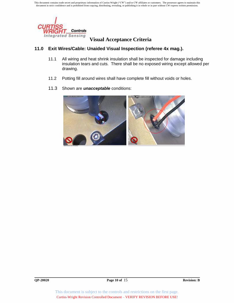
11.0 Exit Wires/Cable: Unaided Visual Inspection (referee 4x mag.).
11.1 All wiring and heat shrink insulation shall be inspected for damage including insulation tears and cuts. There shall be no exposed wiring except allowed per drawing.
11.2 Potting fill around wires shall have complete fill without voids or holes.
11.3 Shown are unacceptable conditions:
This document contains trade secret and proprietary information of Curtiss-Wright (“CW”) and/or CW affiliates or customers. The possessor agrees to maintain this
document in strict confidence and is prohibited from copying, distributing, revealing, or publishing it in whole or in part without CW express written permission.
Curtiss-Wright Revision Controlled Document – VERIFY REVISION BEFORE USE!
This document is subject to the controls and restrictions on the first page.

Visual Acceptance Criteria
QP-20020 Page 11 of 15 Revision: B
12.0 Stamping / Marking: Visual Inspection Criteria (no magnification).
12.1 Blurred, illegible or incomplete stamping of information. 12.2 Cage Code shall be correct per customer drawing / CW location.
12.3 Shown are unacceptable conditions:
This document contains trade secret and proprietary information of Curtiss-Wright (“CW”) and/or CW affiliates or customers. The possessor agrees to maintain this
document in strict confidence and is prohibited from copying, distributing, revealing, or publishing it in whole or in part without CW express written permission.
Curtiss-Wright Revision Controlled Document – VERIFY REVISION BEFORE USE!
This document is subject to the controls and restrictions on the first page.
Visual Acceptance Criteria
QP-20020 Page 12 of 15 Revision: B
13.0 Non-conformances
13.1 Non-conformances shall be processed per applicable procedures for the CW manufacturing site. Product shall be placed in quarantine until disposition by the appropriate MRB authority.
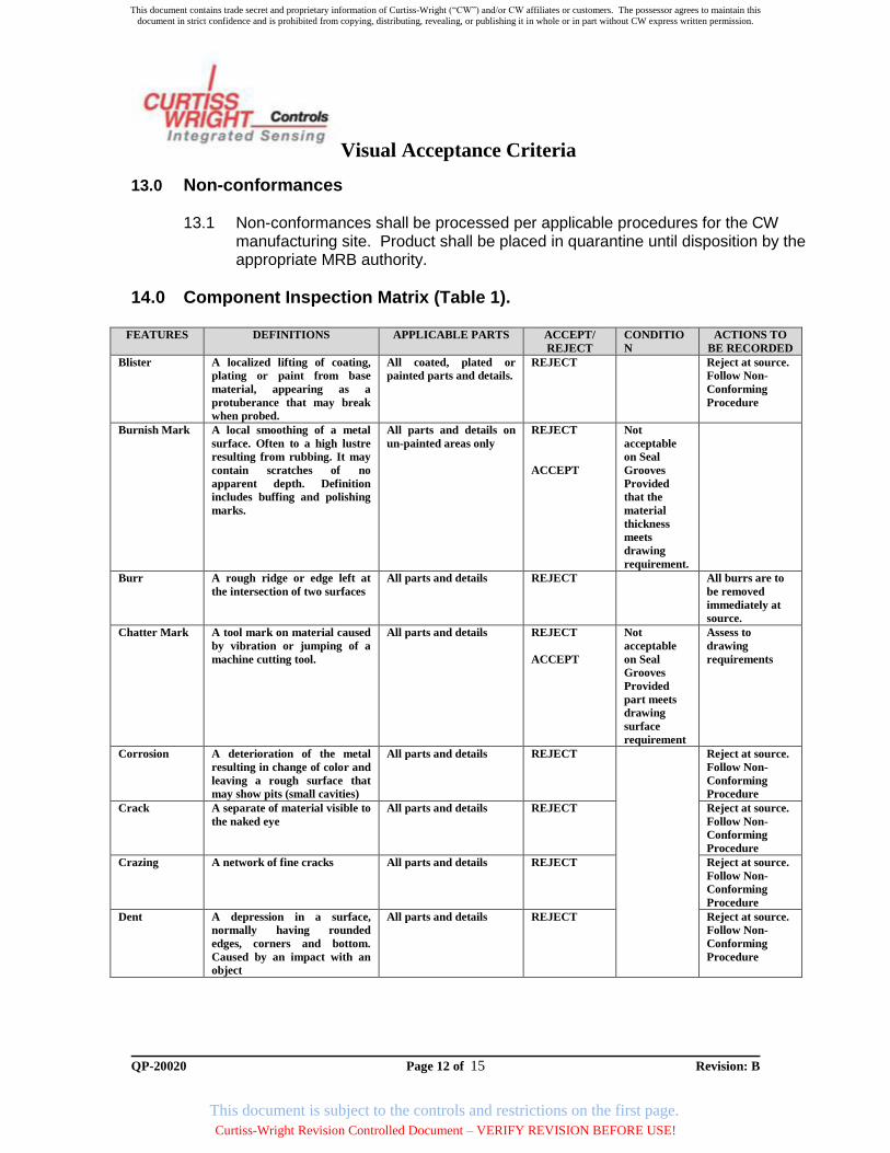
14.0 Component Inspection Matrix (Table 1).
FEATURES DEFINITIONS APPLICABLE PARTS ACCEPT/
REJECT
CONDITIO
N
ACTIONS TO
BE RECORDED
Blister A localized lifting of coating,
plating or paint from base
material, appearing as a
protuberance that may break
when probed.
All coated, plated or
painted parts and details.
REJECT Reject at source.
Follow Non-
Conforming
Procedure
Burnish Mark A local smoothing of a metal
surface. Often to a high lustre
resulting from rubbing. It may
contain scratches of no
apparent depth. Definition
includes buffing and polishing
marks.
All parts and details on
un-painted areas only
REJECT
ACCEPT
Not
acceptable
on Seal
Grooves
Provided
that the
material
thickness
meets
drawing
requirement.
Burr A rough ridge or edge left at
the intersection of two surfaces
All parts and details REJECT All burrs are to
be removed
immediately at
source.
Chatter Mark A tool mark on material caused
by vibration or jumping of a
machine cutting tool.
All parts and details REJECT
ACCEPT
Not
acceptable
on Seal
Grooves
Provided
part meets
drawing
surface
requirement
Assess to
drawing
requirements
Corrosion A deterioration of the metal
resulting in change of color and
leaving a rough surface that
may show pits (small cavities)
All parts and details REJECT Reject at source.
Follow Non-
Conforming
Procedure
Crack A separate of material visible to
the naked eye
All parts and details REJECT Reject at source.
Follow Non-
Conforming
Procedure
Crazing A network of fine cracks All parts and details REJECT Reject at source.
Follow Non-
Conforming
Procedure
Dent A depression in a surface,
normally having rounded
edges, corners and bottom.
Caused by an impact with an
object
All parts and details REJECT Reject at source.
Follow Non-
Conforming
Procedure
This document contains trade secret and proprietary information of Curtiss-Wright (“CW”) and/or CW affiliates or customers. The possessor agrees to maintain this
document in strict confidence and is prohibited from copying, distributing, revealing, or publishing it in whole or in part without CW express written permission.
Curtiss-Wright Revision Controlled Document – VERIFY REVISION BEFORE USE!
This document is subject to the controls and restrictions on the first page.

Visual Acceptance Criteria
QP-20020 Page 13 of 15 Revision: B
FEATURES DEFINITIONS APPLICABLE PARTS ACCEPT
/REJECT
CONDITIO
N
ACTIONS TO
BE RECORDED
Dis-coloration A localized or generalized
change of color of the part.
Definition includes etching
All heat treated parts and
details made of steel,
nickel alloys
ACCEPT Provided it is
an even light
straw or
light blue in
color and
free of
corrosion
All nitride parts and
details
ACCEPT Provided it is
light to dark
grey in color
All Anodized parts ACCEPT Provided it is
uniform light
grey
All Hard Anodized parts ACCEPT Provided it is
adherent,
uniform in
colour and
not powdery
Alocrom ACCEPT Provided it is
a uniform
gold/yellow
colour. Some
variation is
allowable in
touch up
areas.
Contact QA
Contact QA in
regards to touch
ups
Electroless nickel plated
steel parts which have
been subject to a thermal
deposit hardening
process (bake) in a non-
inert atmosphere e.g.
SAE AMS 2404, Class 2.
ACCEPT Any shade of
light yellow
to dark
peacock
blue/purple,
and any
variability
across the
part is
acceptable
Fettling Removal of excess material or
surface defects from casting
flash/forging seams and other
similar parts
All parts and details ACCEPT Provided
parts are
blended and
uniformed.
Drawing
limits must
be
maintained.
Finger Print Stains left by unprotected
hands
All parts and details ACCEPT Provided
action is
taken to
clean the
component
Remove
immediately at
source
Fleck Marks A vertical cut mainly caused by
debris in cutting fluids
All ground diameters Unacceptable
if there is more
than one
indication on
the same axis
Reject at source.
Follow Non-
Conforming
Procedure
Flaking/Scale Loose, scale like fragments on a
surface
All parts and details REJECT Reject at source.
Follow Non-
Conforming
Procedure
This document contains trade secret and proprietary information of Curtiss-Wright (“CW”) and/or CW affiliates or customers. The possessor agrees to maintain this
document in strict confidence and is prohibited from copying, distributing, revealing, or publishing it in whole or in part without CW express written permission.
Curtiss-Wright Revision Controlled Document – VERIFY REVISION BEFORE USE!
This document is subject to the controls and restrictions on the first page.

Visual Acceptance Criteria
QP-20020 Page 14 of 15 Revision: B
FEATURES DEFINITIONS APPLICABLE PARTS ACCEPT
/REJECT
CONDITIO
N
ACTIONS TO
BE RECORDED
Superficial
Scratch
CAT 1
A scratch that has no apparent
depth (cannot be felt by probe)
Less than 10mm
All parts and details ACCEPT Rework
options will
apply if
deemed
applicable
Mend, blend. Re-
anodize (if req’d)
superficial
scratches.
Wider Scratch
Marks
CAT 2
A scratch which has occurred
in a treated/coated material and
is CLEARLY visible in normal
lighting conditions (i.e. not
superficial as above)
All parts and details REJECT Due to the
width of the
scratch the
appearance
of the
surface is
extremely
poor and is
IMMEDIAT
ELY evident
to the
inspector
Reject at source.
Follow non-
conformance
procedure.
Scratch with
apparent depth
CAT 3
Significant damage of surface
area in length and depth and
can be felt be a probe
All parts and details REJECT Major
damage with
significant
depth
Reject at source.
Follow non-
conformance
procedure.
Scratch on
sealing surface,
critical bore
with apparent
depth.
CAT 4
The scratch is NOT purely
superficial (as above) AND the
scratch is likely to cause a loss
of functionality or performance
due to its location
All parts and details REJECT Scratch is on
a critical
area or
surface/bore,
Further
consultation
is required if
unsure
whether area
is critical
Reject at source.
Follow non-
conformance
procedure.
Stain or excess
process
material
Local visual indication resulting
from liquid drying on parts e.g
Alocrom. Includes ANY process
material which is visible on the
component.
All parts and details ACCEPT
REJECT
Provided
there is no
visible
change in
height and
excess has
been cleaned.
Must meet
drawing
requirement
If excess
material
remains
after
cleaning
Remove excess
immediately at
source.
This document contains trade secret and proprietary information of Curtiss-Wright (“CW”) and/or CW affiliates or customers. The possessor agrees to maintain this
document in strict confidence and is prohibited from copying, distributing, revealing, or publishing it in whole or in part without CW express written permission.
Curtiss-Wright Revision Controlled Document – VERIFY REVISION BEFORE USE!
This document is subject to the controls and restrictions on the first page.

Visual Acceptance Criteria
QP-20020 Page 15 of 15 Revision: B
FEATURES DEFINITIONS APPLICABLE PARTS ACCEPT
/REJECT
CONDITIO
N
ACTIONS TO
BE RECORDED
Step An abrupt change in a surface
profile or a mismatch between
two or more surfaces
All machines parts and
details
ACCEPT Provided it
complies
with drawing
requirement
Examine against
drawing
requirements.
Follow non-
conformance
procedure if
required.
Surface Finish The result of the machining
process defines by the drawing
surface finish requirement
All machined parts and
details
ACCEPT MUST meet
drawing
requirement
Tool Mark A mark in the direction of the
machining lay left by the
machining tool or across the lay
caused by tool withdraw or
metal chips. Marks can be
straight, circular or spiral. Can
also be caused by a dull or
broken tool.
All machined parts and
details
ACCEPT Provided
part meets
drawing
surface
requirement
and does not
fail CAT 1
Examine against
drawing
requirements.
Follow non-
conformance
procedure if
required.
Undercut A groove or recess cut into a
surface near a shoulder or
other projection
All machined parts and
details
ACCEPT Provided it
blends
smoothly
with
adjacent
surfaces and
that it is
within
drawing
tolerances.
Examine against
drawing
requirements.
Follow non-
conformance
procedure if
required
15.0 Records.
The preservation, storage and period of records must be in accordance to applicable Records Control procedures per CW manufacturing site.
Appendix A – Additional Change Details Issue B - Update to section 14 “Discoloration” with respect to Electroless nickel plated steel parts which have been subject to a thermal deposit hardening process (bake) in a non-inert atmosphere e.g. SAE AMS 2404, Class 2. Rationale as follows: Discoloration occurs due to the formation of nickel sulfate when the parts undergo thermal deposit hardening in the presence of moisture from the atmosphere. There are at least 7 nickel sulfate salts which differ in their hydration or crystal habit, resulting in the range of colors from light yellow to dark peacock blue/purple. Small variances in moisture or humidity will cause a range of these colors to be evident within a single part or batch of parts, and this is completely normal. SAE AMS 2404, Class 2 specifically states that discoloration may occur and is acceptable. As additional proof, sample parts demonstrating the greatest variation have been subject to copper sulfate tests to prove that iron is not present.
This document contains trade secret and proprietary information of Curtiss-Wright (“CW”) and/or CW affiliates or customers. The possessor agrees to maintain this
document in strict confidence and is prohibited from copying, distributing, revealing, or publishing it in whole or in part without CW express written permission.
Curtiss-Wright Revision Controlled Document – VERIFY REVISION BEFORE USE!
This document is subject to the controls and restrictions on the first page.

Curtiss-Wright CorporationDoc-Sign
Document Approval
Document Title :
Date :
OBJECTIVE :
REVIEWED BY (All signatures must show typed name and title)
SIGNATURE / DATE
SIGNATURE'S :
Prepared By
This document contains trade secret and proprietary information of Curtiss-Wright (“CW”) and/or CW affiliates or customers. The possessor agrees to maintain this
document in strict confidence and is prohibited from copying, distributing, revealing, or publishing it in whole or in part without CW express written permission.
Curtiss-Wright Revision Controlled Document – VERIFY REVISION BEFORE USE!
This document is subject to the controls and restrictions on the first page.