early focus on temporary works and buildability · infrastructure projects date: 16.04.2016...
TRANSCRIPT
Infrastructure Projects Date: 16.04.2016 Guidance Note – Early Focus on Temporary Works and Buildability Issue: 2
Page 2 of 40
Table of Contents 1.0 Purpose / Background ........................................................................................................... 3
2.0 Scope ..................................................................................................................................... 4
3.0 Maintaining Operations (Business as Usual) ......................................................................... 4
4.0 Engineering Management for Projects: NR/L2/INI/02009 ...................................................... 5
5.0 Collaboration, Teamwork, and Communication ..................................................................... 6
6.0 Focus and Planning ............................................................................................................... 6
7.0 Competence and Expertise .................................................................................................... 7
8.0 Capturing and Cascading Lessons Learned .......................................................................... 7
9.0 Understanding the Site: Record Information, Surveys, Logistics, and Access ...................... 8
10.0 Buildability Reviews ............................................................................................................. 8
11.0 Validation of Design Assumptions / Exclusions ................................................................... 9
12.0 Early Contractor Involvement ............................................................................................. 10
13.0 Engineering Assurance of Temporary Works .................................................................... 11
14.0 Changes to Temporary Works ........................................................................................... 12
15.0 Piling Rig/Crane Working Platforms ................................................................................... 14
16.0 Hoardings ........................................................................................................................... 15
17.0 Protection Decks and Dropped Loads ............................................................................... 15
18.0 Earthing and Bonding of Metallic Structures/Elements on AC & DC Electrified Lines ....... 18
19.0 Gauging and Electrical Clearances .................................................................................... 19
20.0 Use and mis-use of proprietary products ........................................................................... 20
21.0 Demolition and Dismantling ............................................................................................... 21
22.0 Construction Sequence as part of the Design ................................................................... 22
23.0 Risk of Earthworks Instability due to Temporary Excavations ........................................... 24
24.0 Temporary works affecting track geometry ........................................................................ 26
25.0 Safe Loading, Lifting, and Transportation .......................................................................... 26
26.0 Scaffolding ......................................................................................................................... 27
27.0 Listed Buildings and Structures ......................................................................................... 29
28.0 Communication of Temporary Works Requirements and Design Philosophy ................... 29
Appendix A: Example of a Buildability Review ............................................................................ 30
Appendix B: Key Statutory Requirements and Guidance ........................................................... 34
Appendix C : Useful References / Resources ............................................................................. 37
Appendix D: Key Points …………………………………………………………….39
Infrastructure Projects Date: 16.04.2016 Guidance Note – Early Focus on Temporary Works and Buildability Issue: 2
Page 3 of 40
Acknowledgements. This revised guidance has been prepared by Tom Hyland and Steve Williams of NR, with assistance gratefully received by others including:-
Neil Sadler: Cass Hayward. Peter Wright: Richter Associates. Andy Wrennall: Carillion.
1.0 Purpose / Background
The purpose of this document is to improve awareness of, and to promote early focus on, Buildability and Temporary Works.
Buildability is defined as:
“the extent to which the design of a building or construction project facilitates ease of construction, subject to the overall requirements of the building or construction project”
Temporary works can be defined as:-
“those parts of the works that allow or enable construction of, protect, support or provide access to, the permanent works and which might or might not remain in place at the completion of the works, including states of the permanent works which are temporary, loading conditions of the permanent works not envisaged by the permanent works design and structures in states of modification or demolition.”
Network Rail Infrastructure Projects experiences a disproportionately high number of incidents / problems in this area of our business, some of which have had serious consequences including injuries, operational disruption, cancelation of work, and “last minute” re-working which in itself imports safety risk.
Proper understanding and planning for Buildability and Temporary Works is a pre-requisite for the safe and smooth running of our projects and failure to do this imports unnecessary risk.
This document endeavours to capture best practice and experience, particularly with respect to design and implementation of temporary works within a railway environment.
Key points are listed in Appendix D.
Infrastructure Projects Date: 16.04.2016 Guidance Note – Early Focus on Temporary Works and Buildability Issue: 2
Page 4 of 40
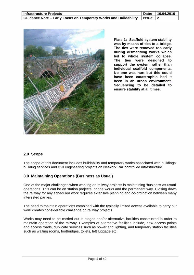
Plate 1: Scaffold system stability was by means of ties to a bridge. The ties were removed too early during dismantling works which led to whole system collapse. The ties were designed to support the system rather than individual scaffold components. No one was hurt but this could have been catastrophic had it been in an urban environment. Sequencing to be detailed to ensure stability at all times.
2.0 Scope
The scope of this document includes buildability and temporary works associated with buildings, building services and civil engineering projects on Network Rail controlled infrastructure.
3.0 Maintaining Operations (Business as Usual)
One of the major challenges when working on railway projects is maintaining ‘business-as-usual’ operations. This can be on station projects, bridge works and the permanent way. Closing down the railway for any scheduled work requires extensive planning and co-ordination between many interested parties.
The need to maintain operations combined with the typically limited access available to carry out work creates considerable challenge on railway projects.
Works may need to be carried out in stages and/or alternative facilities constructed in order to maintain operation of the railway. Examples of alternative facilities include, new access points and access roads, duplicate services such as power and lighting, and temporary station facilities such as waiting rooms, footbridges, toilets, left luggage etc.

Infrastructure Projects Date: 16.04.2016 Guidance Note – Early Focus on Temporary Works and Buildability Issue: 2
Page 5 of 40
Shutting down of the railway for carrying out work is costly; unscheduled over running of work can be very costly. Work carried out in such circumstances normally has strict time constraints and detailed half hour increment planning is normally required to ensure that ‘hand back’ of the railway infrastructure can be safely achieved.
Under such conditions ‘safe by design’ is critical when assessing optimised solutions for all aspects of the work to be undertaken. Safety systems for personnel and materials handling must be considered and incorporated into all permanent and temporary work designs.
Those planning the works must consider whether or not a safe system of work can be established that allows the railway to continue running. If a safe and practicable system cannot be identified then the works may need to be undertaken when the railway is shut.
4.0 Engineering Management for Projects: NR/L2/INI/02009
This is a key Network Rail standard which describes the processes and roles and responsibilities of staff responsible for the management of the technical and engineering requirements of projects for and on behalf of Network Rail. This applies to all projects and the organisations working on projects that change, renew, enhance or remove Network Rail infrastructure assets. It applies to all phases of a project as applicable under GRIP. All types of project are applicable including, but not limited to:
a) feasibility studies; b) design; c) construction; d) testing and commissioning; e) maintenance; f) asset protection; g) asset recovery; h) de-commissioning and demolition; i) projects which protect Network Rail’s asset when a party other than Network Rail carries out work on, over or under Network Rail property; j) projects carried out by an Alliance between Network Rail and another party / other parties (refer to Clause 5 for further information); k) temporary works; l) emergency works (once the immediate requirements to make the railway safe have been met.
There are a number of exceptions, as listed in the standard. This standard applies to projects which protect Network Rail’s asset when a party other than Network Rail carries out work on, over or under Network Rail property. The requirements defined within the standard detail responsibilities aligned to elements of the CDM Regulations. NR/GN/OHS/0047 and NR/L2/OHS/0047 defines the full responsibilities to achieve compliance with the CDM Regulations.
All IDC and IDR shall be conducted in accordance with guidance provided within the NR/L2/INI/02009. The processes used for this shall reflect the complexity of the designs and interfaces involved and, provide a robust auditable trail.
Read this section with section 13.
Infrastructure Projects Date: 16.04.2016 Guidance Note – Early Focus on Temporary Works and Buildability Issue: 2
Page 6 of 40
5.0 Collaboration, Teamwork, and Communication
Construction projects can vary from the relatively straightforward to hugely complex. No single person will know solutions to the myriad of challenges that must be overcome to safely and successfully deliver a project. However the collective skills and expertise of those involved, if correctly harnessed, is a recipe for safety and success.
Working together collaboratively as a project team with regular open and honest communication engenders an atmosphere of mutual support and learning thereby maximising the probability of success.
It is the duty of professionals to understand the limits of their competence and seek advice when needed. Making the best use of available resources can enhance their own knowledge, and enhance their technical support network. Competence of individuals to be assessed by a competent person.
Further guidance on collaboration can be found in BS11000.
6.0 Focus and Planning
Many of the problems caused by buildability and/or temporary works are due to lack of focus and planning at an early enough stage in the project. Lack of focus and planning at an early enough stage leads to late procurement, late submissions, compressed review times, disruption to works, lack of understanding, and mistakes.
Buildability based upon the site and its constraints should be reviewed at a number of stages of a project, particularly at feasibility, option selection, and detailed design. On complex projects it may be necessary to hold buildability reviews as design develops and understanding of the design and construction issues increases.
An early understanding of temporary works requirements and staging is essential in order to robustly understand the true scope of works and the associated risks. To achieve this the early involvement of Designers with confirmed Temporary Works and Buildability Competencies is of great benefit. This will most likely be achieved by ensuring the Contractor appointment has a appropriate design competency either in-house or out-sourced. It might also be beneficial for NR to input into this appointment based on direct experiences of the Designers proposed. (Refer also to section 12.0)
Designers and Contractors should also provide a Temporary Works Schedule at the earliest possible stage. All parties can then review and comment to gather the broadest possible views on Temporary Works and Buildability.
Buildability reviews should encompass assessments of Temporary Works at an early stage.
Infrastructure Projects Date: 16.04.2016 Guidance Note – Early Focus on Temporary Works and Buildability Issue: 2
Page 7 of 40
7.0 Competence and Expertise
Working within the railway environment requires knowledge of the constraints when carrying out designs that interface with a live railway.
Industry research has identified significant changes since the 1970’s in the way the construction industry deals with temporary works and particularly its design. A reduction in the number of Contractors’ in-house temporary works departments and the increased usage of proprietary systems has led to more responsibilities being with specialist contractor/suppliers and to problems associated with lengthy supply chains where, quite commonly, design and erection responsibility are divided. The roles of TWC (Temporary Works Coordinator), Principal Designer and CEM need to recognize the risks of multi-tiered temporary works design and ensure that the transfer of information is seamless.
Designers / Engineers with combined knowledge of the live railway and temporary works are not always available to place on a railway contract. If experienced personnel are not readily available and the information can’t be easily disseminated through the lessons learnt process and in all cases recourse to a detailed design brief should be made. The brief can be created by someone (or a team of people) who have a detailed understanding of the constraints involved.
In all cases Engineers/Designers CVs should be sought at an early stage to enable verification of knowledge and expertise that exists within the proposed team. In the case of nominating a Contractor’s Responsible Engineer (CRE) / Contractor’s Engineering Manager (CEM), knowledge of the railway, the design process, and a good understanding of the engineering issues to be addressed should be evident when reviewing their CV’s.
Further to the consideration of competence of individuals, the competence and in particular, relevant competence, of the Design Organisation should be reviewed. Individual CVs yield a certain amount of information but the Design Organisation responsible for buildability / temporary works design should be able to demonstrate experience of projects of similar size and complexity. For example previous experience in basic scaffold design would not necessarily be sufficient for a complex scaffold bridging scheme. Apart from a direct approach for any given project, access to information via the RISQS system should be of assistance in this review.
Time taken at this stage in selecting the right personnel and organisation will result in quicker and better quality approvals and better turnaround of engineering deliverables (such as Forms 001, 002 & 003 (as defined in NR/L2/CIV/003 ‘Engineering assurance of building and civil works) and Work Package Plans (WPPs)).
8.0 Capturing and Cascading Lessons Learned
Over the years of construction work and infrastructure development during British Rail, Railtrack and Network Rail, tenure of the railways has amassed a vast pool of knowledge regarding safe methods of working. This information is routinely recorded and stored for use when planning and designing future work.
Network Rail organise ‘lessons learnt’ sessions at key stages throughout projects. The key challenge is for the lessons learnt information to be known at the time of planning work. Seeking this information at the outset of any project work will result in an increasingly safe environment for all.
Infrastructure Projects Date: 16.04.2016 Guidance Note – Early Focus on Temporary Works and Buildability Issue: 2
Page 8 of 40
It is important to understand what you do not know and seek advice from colleagues/contacts as appropriate. Furthermore, CEMs and CREs should seek advice/opinion from Network Rail engineers.
At the time of publication NR have plans to make Lessons Learned and Good Practice examples available to all in the industry through a single platform, to compliment information already available on Safety Central. At time of publication the following links are available:-
Safety Central:-
https://www.safety.networkrail.co.uk
Lessons Learned:-
https://www.safety.networkrail.co.uk/Alerts-and-Campaign/Lessons-Learnt
Good practice library:-
http://oc.hiav.networkrail.co.uk/programmes/IIIP/IPPM/PSE/BPL/default.aspx
Note. NR intends to develop a centrally based searchable depository for lessons learned and good practice during CP5.
9.0 Understanding the Site: Record Information, Surveys, Logistics, and Access
Designing a scheme without an appropriate understanding of the site is fundamentally flawed.
Construction sites in a railway environment often bring a unique set of challenges. Key record information held by the Client must be provided at an early stage to the other CDM duty holders to help assist them with the safe planning and development of construction works. If there is insufficient record information available a prioritised schedule of survey requirements should be formulated by the Designer.
Validation of records drawings may be necessary and should be accommodated.
Designers should familiarise themselves with the site and the available access and transportation logistics, both in terms of time and location, in order for these issues to inform their design.
10.0 Buildability Reviews
A designer’s ability to influence safety is considered by some researchers to be greatest in the earliest stages of a project.
Designers should undertake buildability reviews at various stages of a project. The chosen stages may vary to suit complexity, design development, or changes to access or site conditions. Attendance at buildability reviews should not be limited to the design team and the involvement of contractors and/or other independent construction professionals or peers is encouraged.
Infrastructure Projects Date: 16.04.2016 Guidance Note – Early Focus on Temporary Works and Buildability Issue: 2
Page 9 of 40
As a minimum, buildability reviews are suggested at the following stages as appropriate:-
Feasibility Option Selection Commencement of detailed design Completion of detailed design Commencement of construction
The agenda or check list for reviews can be tailored to suit a particular project, however, on railway projects the following topics should be considered for inclusion:
Possession availability Physical features of site, e.g. topography and ground conditions. Physical access Transportation and storage of materials Environmental issues including noise, fumes etc. Other projects in the vicinity of the site Condition of existing infrastructure. Changes from previous reviews
Buildability reviews will highlight issues which may affect safety, operations, temporary works requirements etc. and will inform designer risk assessments. This may also include possession availability and design change.
An example of review agenda is included in Appendix A
11.0 Validation of Design Assumptions / Exclusions
It is by no means unusual that designs are underpinned by assumptions, particularly at an early stage. This may be for any number of reasons such as lack of survey data or other engineering discipline designs not being fully developed.
More importantly a specialist designer may have excluded an aspect of the overall design from their commission; furthermore, it may not be obvious and not be expected by the main contractor. For example, a scaffolding structure may need restraint from an existing building and the designer has noted, perhaps in small print, that fixings are to be validated or designed by others.
It is essential that design assumptions and exclusions are clear and transparent. Incorrect assumptions can lead to adoption of non-optimal and/or unsafe design solutions. All design assumptions must be validated. Design exclusions must be identified and addressed as failure to do this may have significant safety implications.
For any project, design needs to be regarded as a single entity even though it may comprise many solutions and involve a significant number of different design organisations involved in permanent and temporary works design. The degree of inter-dependency of the individual facets of the design needs to be understood, managed and communicated and the effective fulfilment of the roles of TWC and Principal Designer are vital in this regard.
Infrastructure Projects Date: 16.04.2016 Guidance Note – Early Focus on Temporary Works and Buildability Issue: 2
Page 10 of 40
Key assumptions and requirements of the Temporary Works Design must be clearly communicated to construction workers and in a way that they can easily understand. This could to be achieved by:
Incorporating Temporary Works Design assumptions and requirements (such as hold / check points) on the drawings
Incorporating Temporary Works Design assumptions and requirements (such as hold / check points) within project specific Work Package Plan(s)
Using a Task Briefing to communicate the Temporary Works Design to construction workers.
Coordination between designer and contractor. Using ERIC principles: eliminate, reduce, inform, control.
It should be stressed to Construction workers that if site conditions change from what has been stated in the Task Briefing they must inform the Contractor’s Responsible Engineer.
12.0 Early Contractor Involvement
Early contractor involvement can take on many forms ranging from informal discussion with industry colleagues/contacts within the contracting sector to formal alliances.
Construction (Design & Management) Regulations (CDM) and associated guidance makes reference to Clients, Principal Designers, Designers involving contractors at an early stage in order to review buildability, among other things.
It is essential that the buildability of designs is understood by designers in order for designs to be robust. Designers do not always necessarily understand buildability of their designs and this is particularly true in a railway environment where access and logistics have significant impacts.
Understanding the constraints faced by contractors may lead to the designer amending their design to facilitate buildability, hence designers are encouraged to seek contractor advice where appropriate. Whilst some projects are relatively straightforward, understanding the buildability issues and phasing of complex projects can have significant effects on designs.
Improved buildability has significant advantages which may include improved safety, programme, and cost, and reduced temporary works.
There is a range of benefits that may be gained by participating in Early Contractor Involvement (ECI), including:
Early creation of delivery team with partnership approach and team ethos based on long-term relationships
More scope for innovation to offer better value Improved risk management Selection of suppliers on the basis of best value Buildable design accounting for best practice
Infrastructure Projects Date: 16.04.2016 Guidance Note – Early Focus on Temporary Works and Buildability Issue: 2
Page 11 of 40
This would likely include the employer, designer, specialist contractors and main contractors working collaboratively. For this process to be successful it is important to:
Involve the Contractors early, but not so early that time is wasted because the project detail is not sufficiently developed for meaningful analysis.
Clarify scope to eliminate gaps and understand the interfaces. Develop a design programme such that, at its completion, a contract can be signed
between the parties in sufficient time for the benefits to be fully realised. Consider any possible conflict of interest between the parties.
ECI is not always the best choice, especially for maintenance activities, but for new build the advantages should be considered.
13.0 Engineering Assurance of Temporary Works
The engineering assurance process is contained in NR/L2/CIV/003. Particular attention should be given to section 5.7.2 which mandates the elevation of check categories dependent upon the relationship between the design and construction organisations. It is fairly common for temporary works to be designed by a contractor’s “in-house” team”
A single temporary works installation may encompass more than one facet of an engineering discipline or competency resulting in the need for more than one design submission. This is best illustrated by an example:
Example
A scaffold needs to be erected on top of an existing station building The railway has 25kV a.c electrification and the scaffold encroaches within 3m of the
Overhead Line Equipment The main contractor employs a scaffolding specialist contractor to design the
scaffolding, however, the scaffolding designer does not have the expertise to check the loads on the existing building
So, the main contractor employs a structural engineer to check the building for the effects of the scaffold loads
As the scaffold requires electrical bonding a specialist electrical engineer is employed to design the bonding. The electrical engineer to also check that there are suitable electrical clearances.
Conclusion
The temporary works installation has three different designers, a scaffolding designer, a structural engineer to check the existing building, and an electrical engineer to design the bonding and check electrical clearances.
Electrical clearances must always be checked. Three separate design submissions are required The main contractor shall carry out an inter-disciplinary check (in accordance with
NR/L2/INI/02009) and submit this with the designs
Infrastructure Projects Date: 16.04.2016 Guidance Note – Early Focus on Temporary Works and Buildability Issue: 2
Page 12 of 40
Where temporary works are required a Temporary Works Schedule should be produced by the Contractor and endorsed by the CEM and attached to the Construction Phase Plan (CPP). The Temporary Works Schedule may be updated as project progresses. The DPE/PE should review and agree the Temporary Works Schedule on NWR behalf. The type of information contained in Temporary Works Schedule, as minimum should include;
Location/description of temporary works
Design check category.
High or low risk check category for Work Package Planning, determined as defined in NR/L3/INICP/0044 and agreed with CEM and DPE/PE
Confirmation of coordination between all permanent and Temporary works has been considered
Date of submission to DPE / PE
Date of acceptance where required by NWR
Details of temporary work design organisation
Interdisciplinary interfaces including but not limited to track monitoring, signal sighting, structure gauging, proximity to electrical systems or consultation with statutory utility companies etc…
Where a CRE Civils is not appointed as a Temporary Works Coordinator then CEM shall propose a separate TWC in accordance with NR/L2/INI/F0040.
Note. Clause 5.6 of NR/L2/CIV/003 applies to Temporary Works whose failure or presence could affect the safety of the railway or the safety of any persons other than those under the control of the construction organisation. Some temporary works don’t have to follow the full Form F002/3 assurance regime.
14.0 Changes to Temporary Works
It is by no means unusual to need to change temporary works installations as works progress in order to suit programme and site logistics. Changes to temporary works may be for such reasons as change of use, revised loadings, partial or phased construction, or removal etc.
It is imperative that temporary works designs are properly evaluated, checked, and accepted at all stages by appropriately qualified competent persons.
Ideally the initial design should foresee and take on board all stages of the temporary works installation, however, if this is not possible particular attention and vigilance should be given to changes to temporary works.
Any proposed changes to the design on site must be effectively communicated to the designer for validation prior to execution of the works.
Infrastructure Projects Date: 16.04.2016 Guidance Note – Early Focus on Temporary Works and Buildability Issue: 2
Page 13 of 40
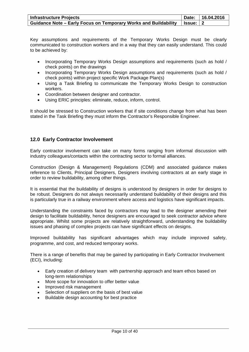
An example of change causing ill effects is Bridge GE19, where permanent works structure fell onto the live railway following launch and following subsequent site adjustments, below:-
Plate 2: GE 19 schematic showing main deck components.
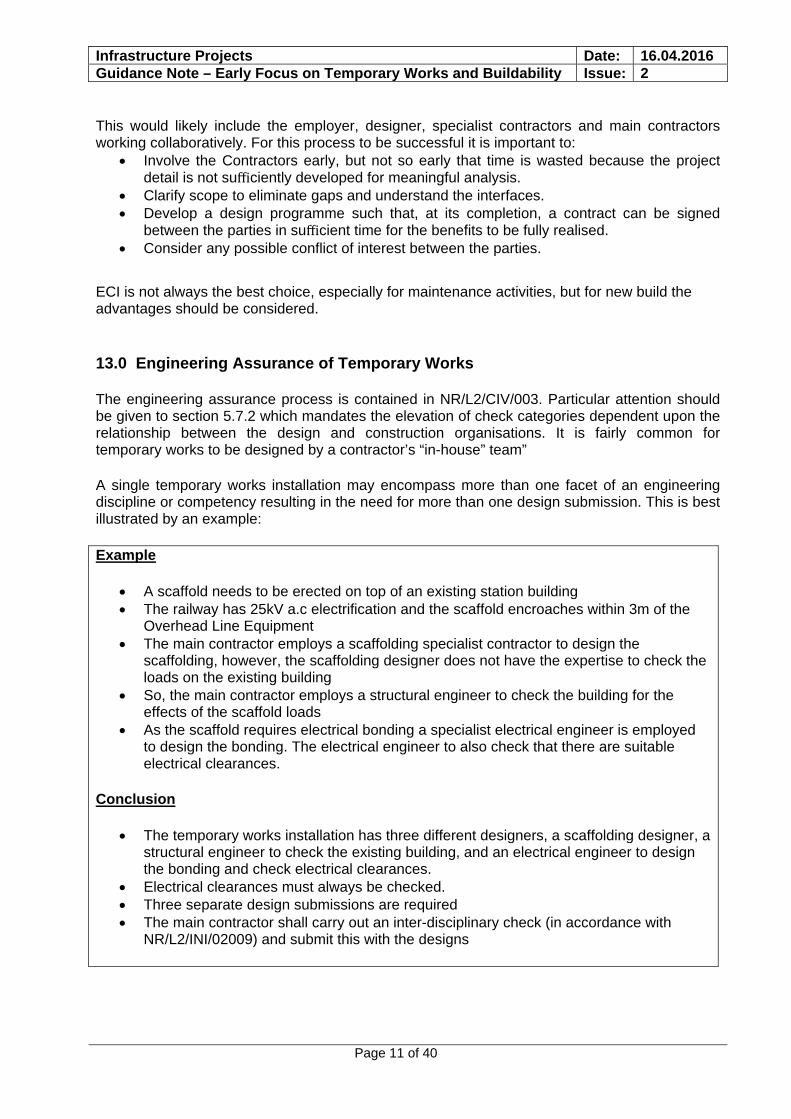
Plate 3: GE19 showing failed components having fallen from bridge over.
GE19. The immediate cause of the accident was concrete planks falling from the partly completed deck of bridge GE19 onto the track below, triggered by a sudden movement of the bridge deck. Train then hit the debris.
There were many causal factors including (but not limited to) the following:-
a. the inadequate planning and lack of design input to the deck repositioning activity, which resulted in the need to ensure the continued stability of the temporary supports at the east abutment being overlooked; b. the unauthorised modification of the temporary support by introducing an additional sliding surface, which made the east abutment supports vulnerable to instability due to horizontal force or movement;
Infrastructure Projects Date: 16.04.2016 Guidance Note – Early Focus on Temporary Works and Buildability Issue: 2
Page 14 of 40
There were many contributory factors including (but not limited to) the following:- a. the lack of accurate or sufficient detail in the steelwork method statement or work plan, which resulted in work outside of the approved documents; b. the hazard identification process not identifying some low probability high impact hazards (eg failure of the temporary works), which were consequently omitted from the steelwork risk assessment for the post-launch phase; c. the Joint Venture’s decision to delegate responsibility for temporary works checks to subcontractor, which meant that they lost visibility of how the structure was performing, or of measures being taken to correct the horizontal movement; d. the absence of post-work checks, which allowed the unstable condition of the east abutment temporary supports and lack of a secondary means of support to go undetected;
15.0 Piling Rig / Crane Working Platforms
The requirements for piling adjacent to the railway are set out in NR/L3/INI/CP0063. The principles of this standard also apply to the use of cranes. Particular attention is drawn to Section 8 which sets out the requirements for design and use of working platforms for piling rigs and cranes. A properly designed and maintained piling / crane platform is a crucial element of temporary works and is key to managing risk associated with these works.
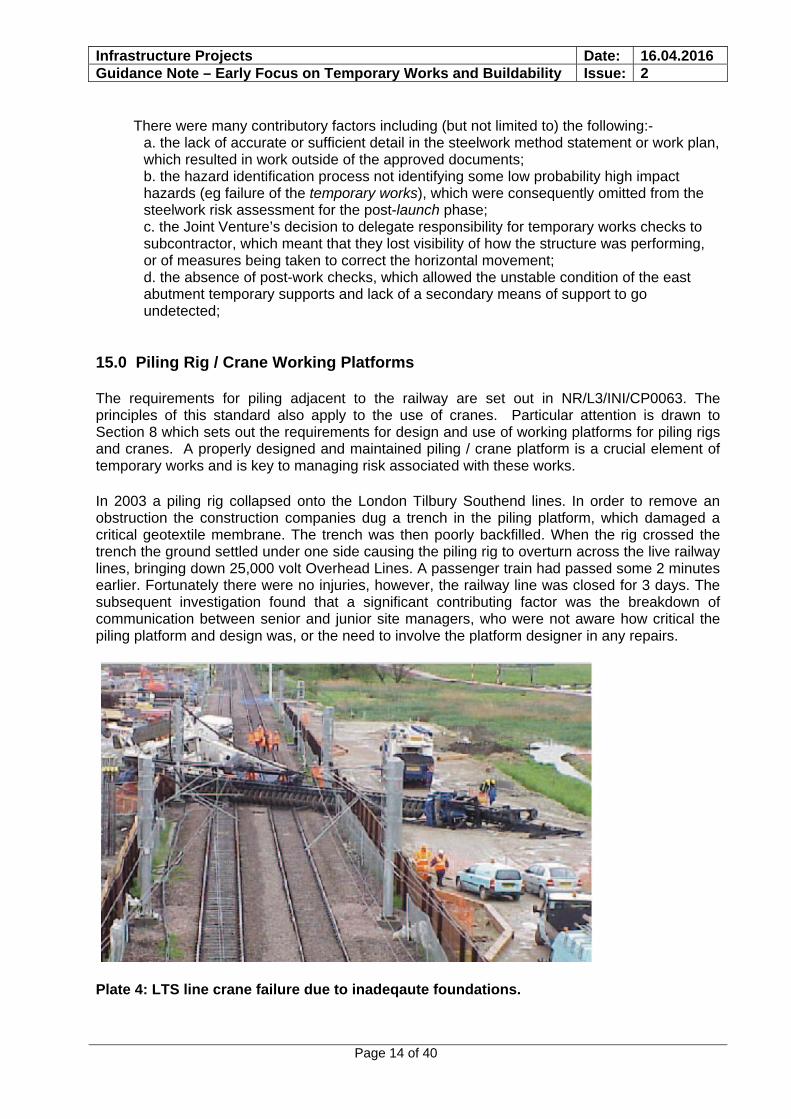
In 2003 a piling rig collapsed onto the London Tilbury Southend lines. In order to remove an obstruction the construction companies dug a trench in the piling platform, which damaged a critical geotextile membrane. The trench was then poorly backfilled. When the rig crossed the trench the ground settled under one side causing the piling rig to overturn across the live railway lines, bringing down 25,000 volt Overhead Lines. A passenger train had passed some 2 minutes earlier. Fortunately there were no injuries, however, the railway line was closed for 3 days. The subsequent investigation found that a significant contributing factor was the breakdown of communication between senior and junior site managers, who were not aware how critical the piling platform and design was, or the need to involve the platform designer in any repairs.
Plate 4: LTS line crane failure due to inadeqaute foundations.
Infrastructure Projects Date: 16.04.2016 Guidance Note – Early Focus on Temporary Works and Buildability Issue: 2
Page 15 of 40
Network Rail recognises that in certain circumstances piling and crane operation restrictions can result in seemingly onerous working practices. In such circumstances consultation and agreement of additional mitigation measures with Network Rail may lead to less onerous working practices. Additional mitigation measures may include establishing a more robustly designed piling platform.
Further guidance is given in Appendix 3 from TWf.
16.0 Hoardings
Hoardings and protection to / from active work is required at all interfaces between construction and non construction/project personnel. Hoardings have the dual purpose of providing a barrier that protects construction operatives from potential danger such as live OLE, third rail and moving rolling stock and non construction/project personnel from injury or harm from construction activities. Specifications for hoarding and protection barriers can be found in British and Network Rail standards. In addition, detailed and useful design guidance can be found in a document produced by the Temporary Works Form (TWf) ref : Hoardings a guide to good practice TWf2012: 01(revised April 2014) Typical key issues for design are:
Fire and flame spread properties Impact and crowd loading Environmental wind loading. Dynamic train pressures. Loading from mobile plant/station platform equipment. Protection against materials from being thrown over a barrier/hoarding. Ensuring that electrical and rail vehicle gauge clearance is not compromised. * Ensuring that signals are not obscured. * Ensuring that sight lines for train despatch staff are not impeded from all locations where
despatch staff are located during despatch. * Ensuring that operational equipment remains accessible. * Ensuring that hoardings do not prevent access for maintenance. * Ensuring that pedestrian flows are safe. It may be necessary to carry out pedestrian flow
modelling to validate the effect of building a hoarding, this is particularly an issue when working in and around railway stations. *
When working on stations hoarding proposals require the agreement of TOCs and/or the Network Rail major station management team. *
Note. - Those items marked with an asterisk should be deemed to be also covered in more detail by the usual IDC/IDR process. It is anticipated that Temporary Works designers should be sufficiently aware of the issues associated with these items such they might be marked as ‘Hazards’ on the Temporary Works drawings, to flag up the need for input required from the relevant design disciplines.
17.0 Protection Decks and Dropped Loads
In areas of work where construction activities are to be carried out over a live railway or station, whilst maintaining ‘business as usual’ operations, a protective/working barrier/deck may need to be installed. The functionality of this barrier can change throughout the duration of any works. Initially the barrier may be in place to provide safe/working access above the railway; as the work progresses the barrier may be required to act as a weather proof layer (i.e. a roof) and may also be required to either support additional access equipment/plant or to be able to sustain an impact force from falling material, equipment or debris.
Infrastructure Projects Date: 16.04.2016 Guidance Note – Early Focus on Temporary Works and Buildability Issue: 2
Page 16 of 40
Early understanding of the full functionality of the proposed protection/working deck is essential if an effective and safe system of work is to be established for all aspects of the work to be undertaken.
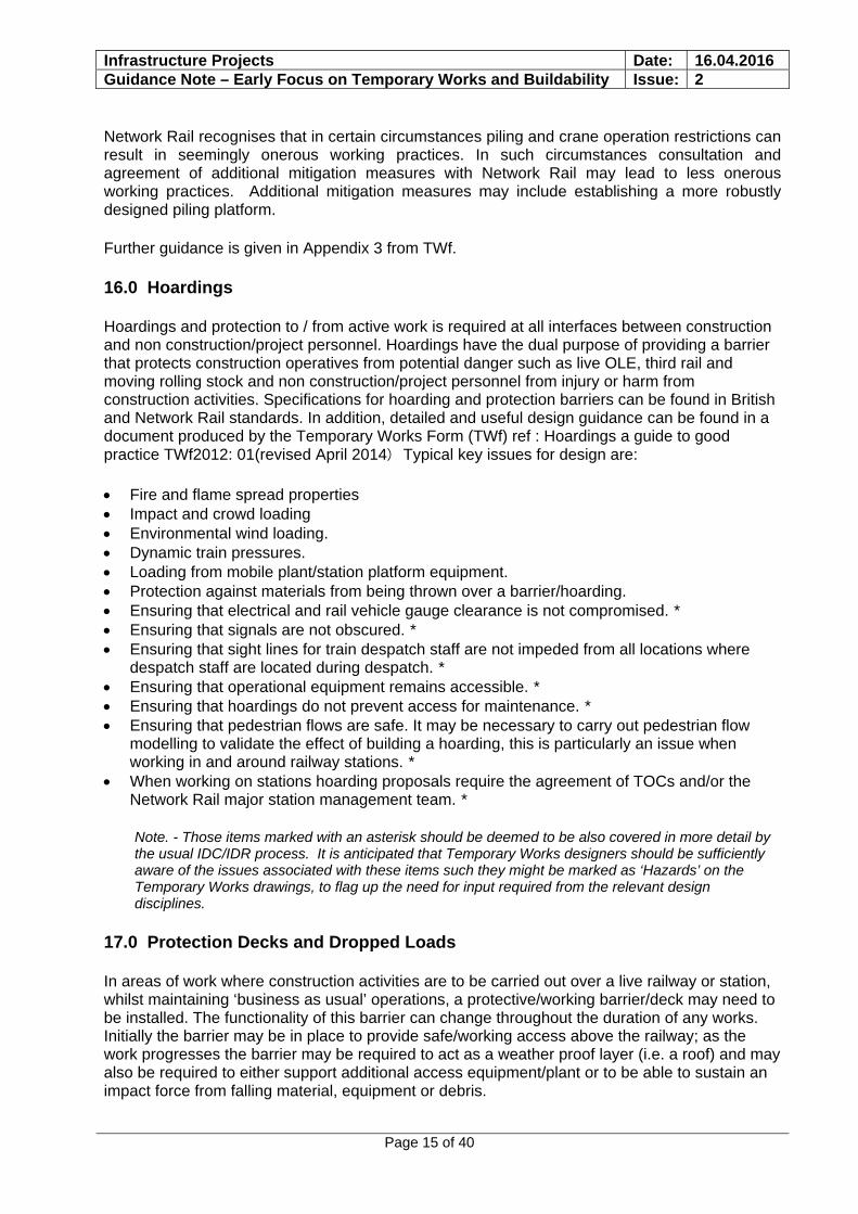
Plate 5: Protection Deck Penetrated By Dropped Loads.
Plate 6: Operational Station with Suspended Protection Deck.
Two metal rod handrails were dropped whilst removing them during a station re-roofing project. The rods penetrated the access deck and landed in the station below. The station was operational. There were no injuries however the safety implications were very significant. The incident led to a review of the protection deck design and working practices with associated delay and disruption to the project.
Infrastructure Projects Date: 16.04.2016 Guidance Note – Early Focus on Temporary Works and Buildability Issue: 2
Page 17 of 40
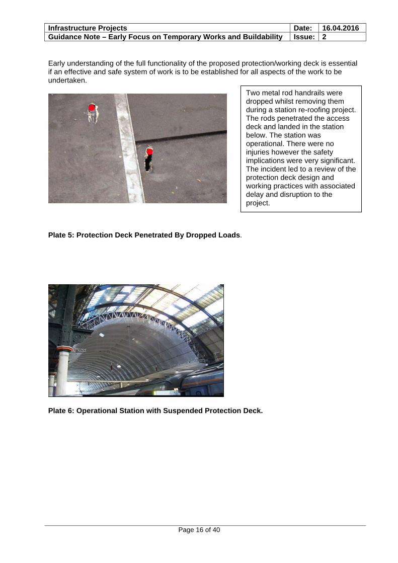
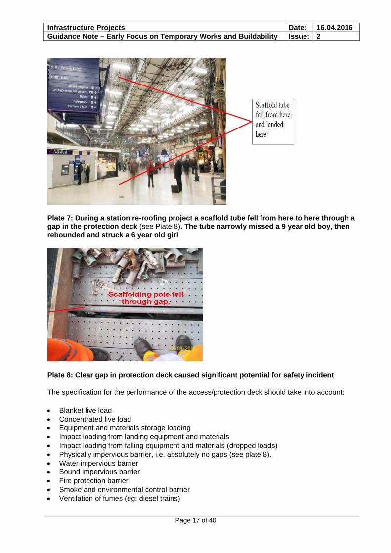
Plate 7: During a station re-roofing project a scaffold tube fell from here to here through a gap in the protection deck (see Plate 8). The tube narrowly missed a 9 year old boy, then rebounded and struck a 6 year old girl
Plate 8: Clear gap in protection deck caused significant potential for safety incident
The specification for the performance of the access/protection deck should take into account:
Blanket live load Concentrated live load Equipment and materials storage loading Impact loading from landing equipment and materials Impact loading from falling equipment and materials (dropped loads) Physically impervious barrier, i.e. absolutely no gaps (see plate 8). Water impervious barrier Sound impervious barrier Fire protection barrier Smoke and environmental control barrier Ventilation of fumes (eg: diesel trains)
Infrastructure Projects Date: 16.04.2016 Guidance Note – Early Focus on Temporary Works and Buildability Issue: 2
Page 18 of 40
Designing/analysing a deck/barrier for dropped loads can be very complex as the weight and shape of objects and the height from which they can fall can all vary significantly. It is necessary to analyse and understand the range of activities which can lead to dropped loads.
It may be appropriate to carry out trials of the deck construction by dropping loads onto it in order to arrive at a design. In fact such drop tests are perhaps the best way of proving the adequacy of the deck and structure and also the best way of providing assurance of the system to all parties concerned.
Mitigation measures such as producing a load management plan or tethering of materials can be used to mitigate risk. It may be that it is not practical to design a crash deck for the full range of loads it may encounter and that certain activities need to be carried out with no operations or personnel below the crash deck. Such limitations must be clearly communicated.
Incorporating all or a combination of some of the above design criteria may lead to conflict of requirements, resulting in a compromise between differing aspects of the design. The decisions as to the better way forward may rest with other constraints, rather than just with impact loading.
18.0 Earthing and Bonding of Metallic Structures / Elements on AC and DC Electrified Lines
Earthing and bonding requirements for temporary (and permanent) metallic structures are frequently missed by designers.
The requirements for the design of earthing and bonding systems for 25kV a.c. electrified lines are described in NR/SP/ELP/21085.
Earthing and bonding are required to ensure a continuous return path for fault current, and to ensure that accessible and touch voltages in excess of acceptable values do not occur. Exposed metal parts of structures and the like must be bonded to the traction return system.
This requirement is regularly missed in design submissions for temporary works in the vicinity of 25 kV a.c. lines. For example scaffolding designs are submitted with input only by the specialist scaffolding designer who is neither aware of this requirement nor has the expertise. In such instances two separate design submissions, one for civil/structural works, and one for electrification will be required.
There is also a need to update/record bonding arrangements to ensure that Network Rail has current earthing/bonding records. The contractor should liaise with the Network Rail maintenance representative to agree how to proceed with respect to sourcing, updating, and handing back records.
If you are designing permanent or temporary works in the vicinity of 25 kV a.c. lines, including stations, you will need to employ specialist expertise in order to satisfy the requirements for earthing and bonding.
It may be acceptable to bond structures to structures which are already bonded, such as Overhead Line masts.
Note that requirements in DC lines are significantly different and requirements shall be to NR/SP/ELP/27192:- Design and Installation of Negative Bonding and Associated Equipment on the High current D.C. Electrified Lines (formerly RT/E/S/27192)
Infrastructure Projects Date: 16.04.2016 Guidance Note – Early Focus on Temporary Works and Buildability Issue: 2
Page 19 of 40
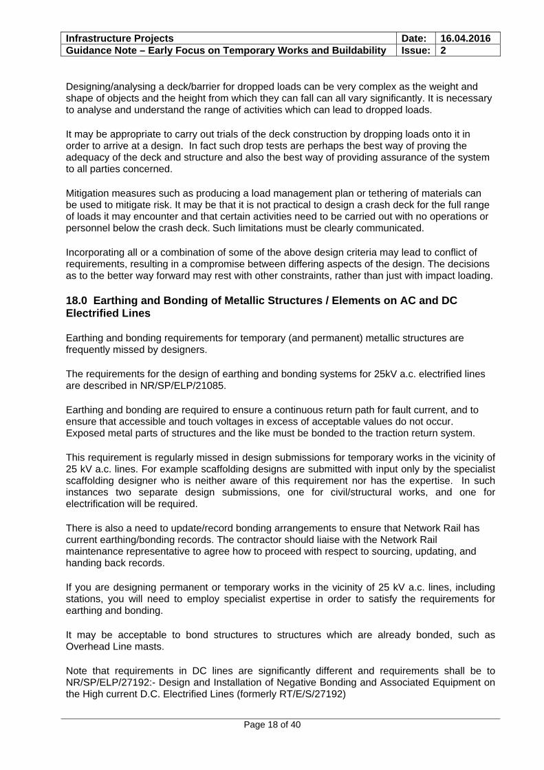
Plate 9: Overhead line masts are electrically bonded to the traction return rail. Steel temporary access deck is bonded to the Overhead Line mast. Design and design acceptance is required
19.0 Gauging and Electrical Clearances
In areas without OLE the Contractor shall design, construct and maintain all Temporary Works to provide minimum clearances as defined in Network Rail Company Standard NR/L2/TRK/2049 as amended by specific project Requirements and NR/L3/TRK/2047/Mod07, regarding G1.1a Standard Structure Gauge and G1.1b Temporary Works Structure gauge.
The Design of a structure carrying or passing over electrified lines must comply with the electrical clearance requirements in GE/RT8025: Electrical protective provisions for electrified lines.
If the Contractor proposes to use less than Enhanced Clearance (as defined in GE/RT8025) this should first be identified in the tender submission and agreed with the Employers Representative.
Examples of lack of compliance with the above are illustrated over:-
Bond taken from mast to temporary structure
Overhead line mast bond to traction return rail
Infrastructure Projects Date: 16.04.2016 Guidance Note – Early Focus on Temporary Works and Buildability Issue: 2
Page 20 of 40
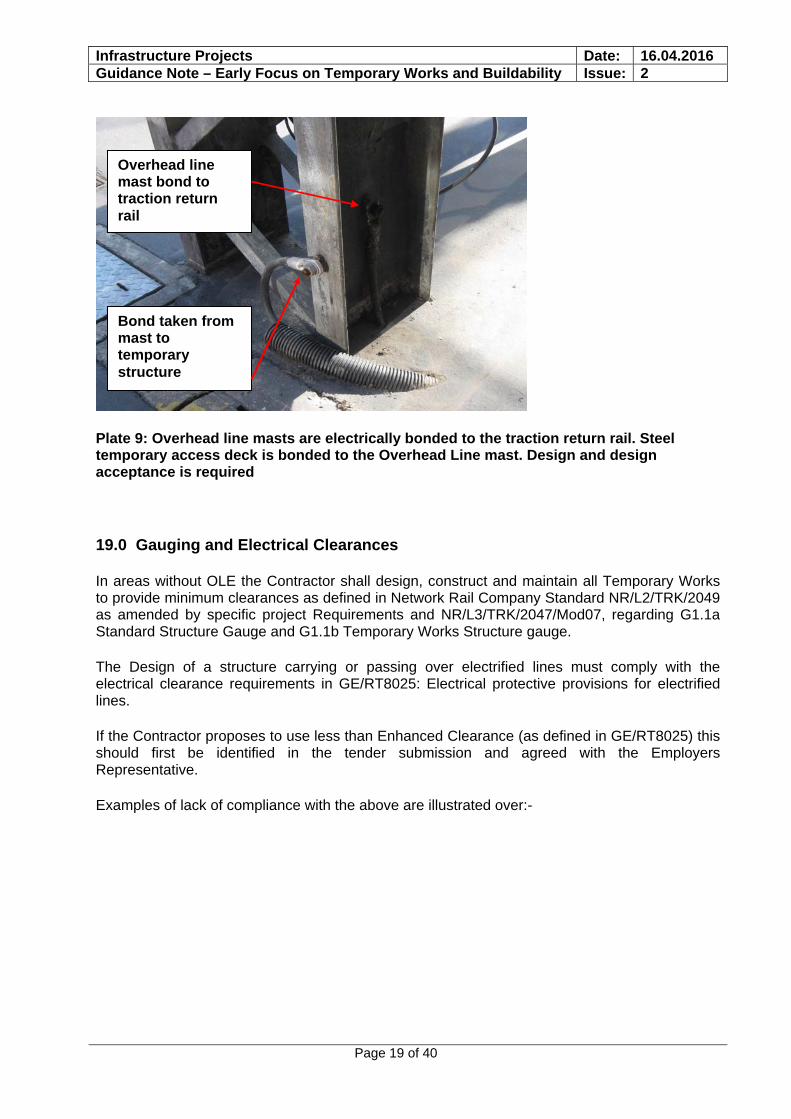
Plate 10: Scaffold constructed within 500mm of live overhead line equipment. Remedial works led to delay and disruption
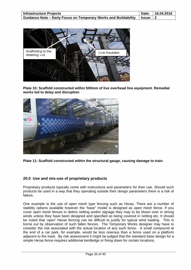
Plate 11: Scaffold constructed within the structural gauge, causing damage to train.
20.0 Use and mis-use of proprietary products
Proprietary products typically come with instructions and parameters for their use. Should such products be used in a way that they operating outside their design parameters there is a risk of failure.
One example is the use of open mesh type fencing such as Heras. There are a number of stability options available however the “base” model is designed as open mesh fence. If you cover open mesh fences in debris netting and/or signage they may to be blown over in strong winds unless they have been designed and specified as being covered in netting etc. It should be noted that ‘open’ Heras fencing can be difficult to justify for typical wind loading. This is borne out by observation of such fallen fences. The Temporary Works designer may have to consider the risk associated with the actual location of any such fence. A small compound at the end of a car park, for example, would be less onerous than a fence used on a platform adjacent to the track. By risk assessment it might be judged that the standard base design for a simple Heras fence requires additional kentledge or fixing down for certain locations.
Infrastructure Projects Date: 16.04.2016 Guidance Note – Early Focus on Temporary Works and Buildability Issue: 2
Page 21 of 40
The same philosophy should be applied to any proprietary product where the risks associated with failure are significant.
Proprietary products should not be used outside their design parameters. If they are to be used in this way they must be properly designed and checked.
21.0 Demolition and Dismantling
All alteration, demolition and dismantling work should be carefully planned and carried out by competent people to avoid unplanned structural collapse. Demolition and dismantling requires a design that incorporates detailed knowledge of the existing structure and how the structure acts.
Further details of the British Standard (BS 6187:2011 Code of practice for full and partial demolition) which gives good practice recommendations for the demolition (both full and partial) of facilities, including buildings and structures are included in Appendix B & C.
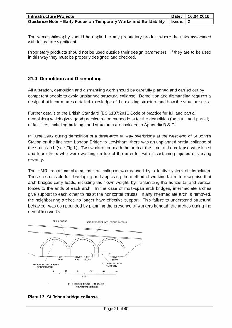
In June 1992 during demolition of a three-arch railway overbridge at the west end of St John’s Station on the line from London Bridge to Lewisham, there was an unplanned partial collapse of the south arch (see Fig.1). Two workers beneath the arch at the time of the collapse were killed and four others who were working on top of the arch fell with it sustaining injuries of varying severity.
The HMRI report concluded that the collapse was caused by a faulty system of demolition. Those responsible for developing and approving the method of working failed to recognise that arch bridges carry loads, including their own weight, by transmitting the horizontal and vertical forces to the ends of each arch. In the case of multi-span arch bridges, intermediate arches give support to each other to resist the horizontal thrusts. If any intermediate arch is removed, the neighbouring arches no longer have effective support. This failure to understand structural behaviour was compounded by planning the presence of workers beneath the arches during the demolition works.
Plate 12: St Johns bridge collapse.
Infrastructure Projects Date: 16.04.2016 Guidance Note – Early Focus on Temporary Works and Buildability Issue: 2
Page 22 of 40
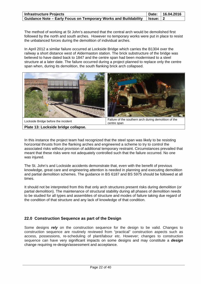
The method of working at St John’s assumed that the central arch would be demolished first followed by the north and south arches. However no temporary works were put in place to resist the unbalanced forces during the demolition of individual arches. In April 2012 a similar failure occurred at Lockside Bridge which carries the B1304 over the railway a short distance west of Aldermaston station. The brick substructure of the bridge was believed to have dated back to 1847 and the centre span had been modernised to a steel structure at a later date. The failure occurred during a project planned to replace only the centre span when, during its demolition, the south flanking brick arch collapsed.
Lockside Bridge before the incident Failure of the southern arch during demolition of the centre span
Plate 13: Lockside bridge collapse. In this instance the project team had recognized that the steel span was likely to be resisting horizontal thrusts from the flanking arches and engineered a scheme to try to control the associated risks without provision of additional temporary restraint. Circumstances prevailed that meant that these risks were not adequately controlled such that the failure occurred. No one was injured. The St. John’s and Lockside accidents demonstrate that, even with the benefit of previous knowledge, great care and engineering attention is needed in planning and executing demolition and partial demolition schemes. The guidance in BS 6187 and BS 5975 should be followed at all times. It should not be interpreted from this that only arch structures present risks during demolition (or partial demolition). The maintenance of structural stability during all phases of demolition needs to be studied for all types and assemblies of structure and modes of failure taking due regard of the condition of that structure and any lack of knowledge of that condition.
22.0 Construction Sequence as part of the Design
Some designs rely on the construction sequence for the design to be valid. Changes to construction sequence are routinely reviewed from “practical” construction aspects such as access, possessions, re-scheduling of plant/labour etc. However; changes to construction sequence can have very significant impacts on some designs and may constitute a design change requiring re-design/assessment and acceptance.
Infrastructure Projects Date: 16.04.2016 Guidance Note – Early Focus on Temporary Works and Buildability Issue: 2
Page 23 of 40
In compliance with CDM regulations designers are required to supply information to both the Principal Designer and the Principal Contractor to indicate the assumptions made in the design about temporary support and sequencing including any significant risks and requirements for temporary works. Some of this information will derive from the designer’s determination of strength and stability of structures, for example, as these develop through the construction process. For instance during the construction of composite steel & concrete beams:-
a) The steel girders may be unstable without temporary bracing during erection b) The steel girders may be unstable without temporary bracing (additional to that required
for (a)) during concrete casting before the concrete has hardened and gained strength. c) The sequence and timing of pouring concrete will dictate the gain of strength (and
geometry) of the composite beams which will influence not only the instability risk in (b) but also the strength of beams to resist these and other subsequent loadings. For multiple structurally continuous spans this assessment can be quite involved. The positions, and reasons for, both longitudinal and transverse construction joints need to be clearly illustrated.
d) Loading effects (vertical and horizontal) imparted by temporary formwork and falsework supporting the wet concrete, as well as construction operations live load allowance, can be significant in dealing with (b) and (c). Contractor’s choices of proprietary falsework systems often vary from those assumed at design stage and can impart different loading regimes which need to be checked.
It is essential that clear and concise information is provided to enable the Contractor to understand the design requirements so that he can plan the construction, design temporary works and be aware of the implications of any proposed changes. Some other simple examples would include:
Temporary propping of insitu concrete beams and slabs Positions of temporary props for bridges envisaged as erected by launching Stability provisions for structural frames for buildings and roofs/canopies
Whilst there has still not yet been a formal report published by HSE, deviation from the Designer’s intended construction sequence of filling around the reinforced pre-cast concrete arched tunnel units is believed to have been a contributory factor in the Gerrards Cross Tunnel collapse during its construction in 2005.
The tunnel was constructed of reinforced pre-cast concrete arched tunnel units and the design specified a sequence of filling around the units from the arch unit springing points with the sequence keeping the fill at approximately the same level either side. Photographic and anecdotal evidence suggests that the design sequence was not followed.
Infrastructure Projects Date: 16.04.2016 Guidance Note – Early Focus on Temporary Works and Buildability Issue: 2
Page 24 of 40
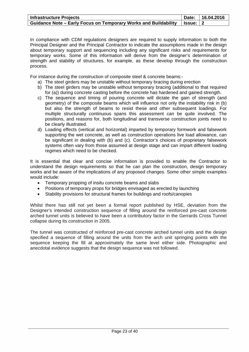
Plate 14: Collapse of Gerrards Cross Tunnel during construction. A train driver at the adjacent station reported that part of the railway had collapsed shortly before he was due to continue his journey through the tunnel. The implications and potential consequences if a train had been under the new tunnel at the time of the collapse could have been catastrophic.
New Civil Engineer magazine 7th July 2005 edition, expressed the opinion that the collapse was triggered by an imbalance in the placement and compaction of the fill, combined with a surcharge of fill over the tunnel crown.
23.0 Risk of Earthworks Instability due to Temporary Excavations
The risk of earthwork instability due to temporary excavations during execution of works requires careful consideration and should be explicitly addressed during the designer risk assessment process, Construction Phase Health and Safety Plan, Work Package Plans and Task Briefings for all applicable projects.
When assessing the risk, the Designer will need to consider a number of factors, including:
Site Investigation information, including: desk study, recent examination and evaluation records, and any records of historic earthwork instability
Ground Investigation information, including: soil strength, stratigraphy, and ground water conditions
The prevailing dead and live loads The location, orientation, depth and extent of the excavation relative to the earthwork
and other sensitive railway infrastructure (such as the tracks, electrification and signalling equipment)
The limits of how long the excavations will be left open prior to being backfilled External factors, such as the potential for inclement wet weather during excavation
works. All earthwork slopes require a geotechnical design (under CDM anyone specifying an
angle of repose is a designer)
Where the designer risk assessment process does not identify the requirement for a formal Temporary Works Design then any construction methodology constraints deemed necessary by the Designer are to be defined in the detailed design and check process for permanent works.
Infrastructure Projects Date: 16.04.2016 Guidance Note – Early Focus on Temporary Works and Buildability Issue: 2
Page 25 of 40
The design risk assessment process should consider the required supervision levels and monitoring regime during (and following) the excavation works.
The assessed risk of earthwork instability during excavation works must be reviewed if site conditions change from that stated in the design. In such cases the Contractor’s Responsible Engineer / Temporary Works Coordinator and the Designer must review methodology and if appropriate propose an alternative temporary works design.
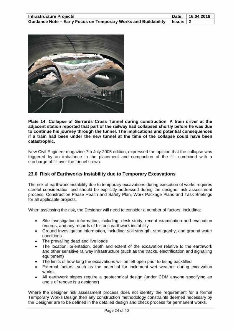
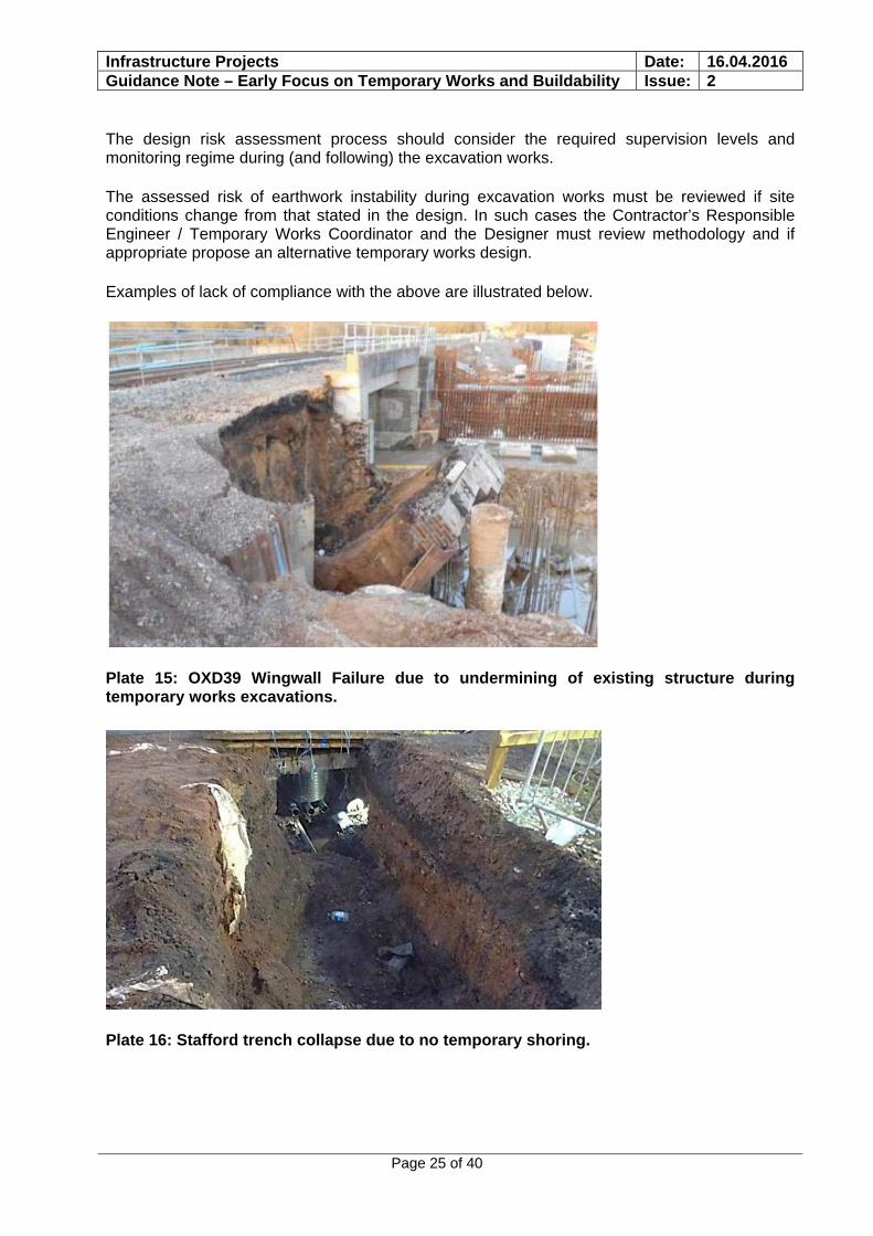
Examples of lack of compliance with the above are illustrated below.
Plate 15: OXD39 Wingwall Failure due to undermining of existing structure during temporary works excavations.
Plate 16: Stafford trench collapse due to no temporary shoring.
Infrastructure Projects Date: 16.04.2016 Guidance Note – Early Focus on Temporary Works and Buildability Issue: 2
Page 26 of 40
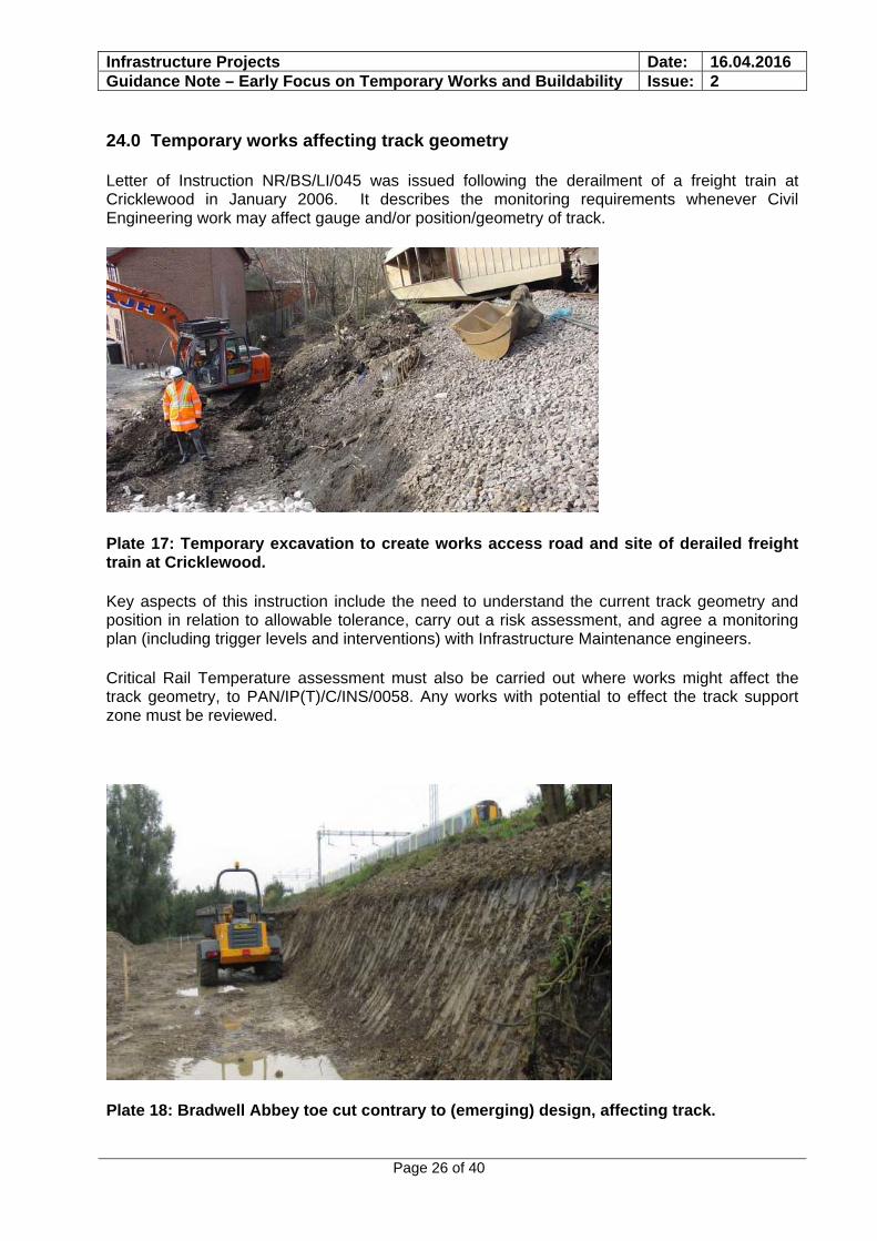
24.0 Temporary works affecting track geometry
Letter of Instruction NR/BS/LI/045 was issued following the derailment of a freight train at Cricklewood in January 2006. It describes the monitoring requirements whenever Civil Engineering work may affect gauge and/or position/geometry of track.
Plate 17: Temporary excavation to create works access road and site of derailed freight train at Cricklewood.
Key aspects of this instruction include the need to understand the current track geometry and position in relation to allowable tolerance, carry out a risk assessment, and agree a monitoring plan (including trigger levels and interventions) with Infrastructure Maintenance engineers.
Critical Rail Temperature assessment must also be carried out where works might affect the track geometry, to PAN/IP(T)/C/INS/0058. Any works with potential to effect the track support zone must be reviewed.
Plate 18: Bradwell Abbey toe cut contrary to (emerging) design, affecting track.
Infrastructure Projects Date: 16.04.2016 Guidance Note – Early Focus on Temporary Works and Buildability Issue: 2
Page 27 of 40
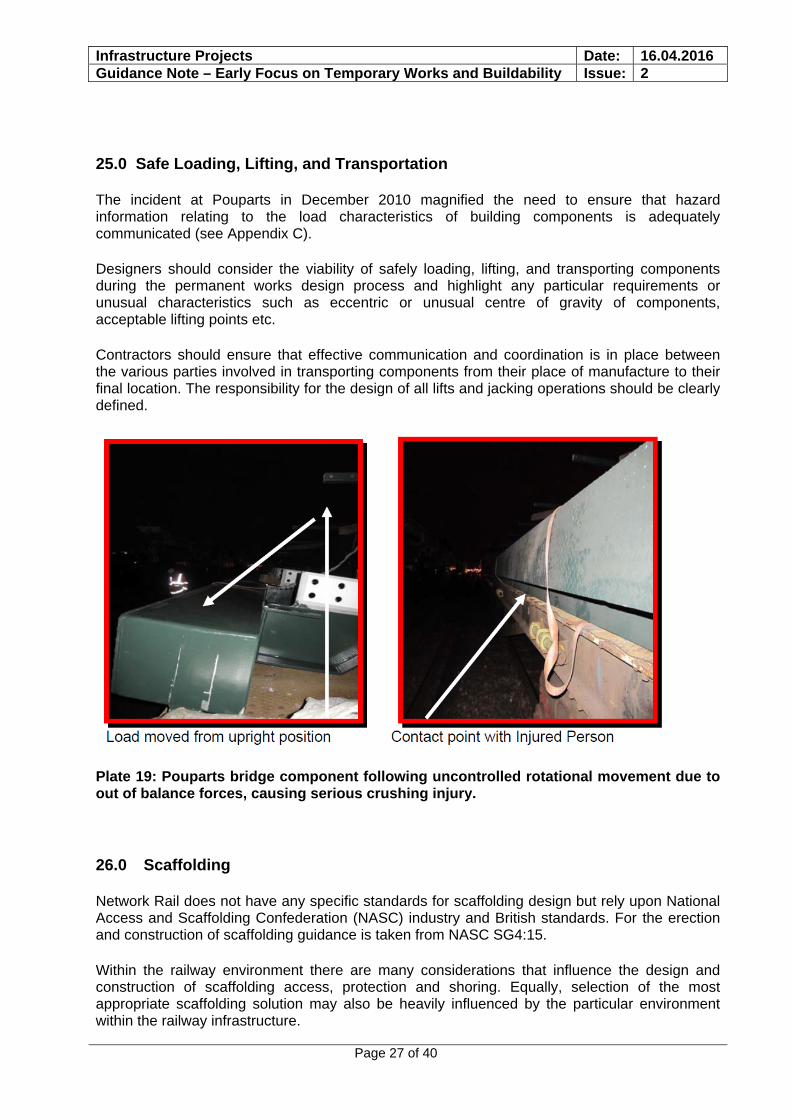
25.0 Safe Loading, Lifting, and Transportation
The incident at Pouparts in December 2010 magnified the need to ensure that hazard information relating to the load characteristics of building components is adequately communicated (see Appendix C).
Designers should consider the viability of safely loading, lifting, and transporting components during the permanent works design process and highlight any particular requirements or unusual characteristics such as eccentric or unusual centre of gravity of components, acceptable lifting points etc.
Contractors should ensure that effective communication and coordination is in place between the various parties involved in transporting components from their place of manufacture to their final location. The responsibility for the design of all lifts and jacking operations should be clearly defined.
Plate 19: Pouparts bridge component following uncontrolled rotational movement due to out of balance forces, causing serious crushing injury.
26.0 Scaffolding
Network Rail does not have any specific standards for scaffolding design but rely upon National Access and Scaffolding Confederation (NASC) industry and British standards. For the erection and construction of scaffolding guidance is taken from NASC SG4:15.
Within the railway environment there are many considerations that influence the design and construction of scaffolding access, protection and shoring. Equally, selection of the most appropriate scaffolding solution may also be heavily influenced by the particular environment within the railway infrastructure.
Infrastructure Projects Date: 16.04.2016 Guidance Note – Early Focus on Temporary Works and Buildability Issue: 2
Page 28 of 40
Apart from the environment, two key determining factors affecting the type of scaffold forms of design and construction are:
the time period over which the scaffold is to remain in position/use the nature of loading to be applied
Scaffolding of a short duration usage will invariably involve the use of standard component parts and should be assessed as rigorously as a scaffold that may have a much longer period of installation. The design of scaffolding erected for short term use is often neglected and the normal engineering assurance processes not undertaken. Design checks and care in construction must be taken for all installations.
The nature of loading applied to scaffolds can vary from light duty access to substantial storage. Scaffolds with heavier loading demand more care in design and construction since factors of safety can become eroded leaving a higher residual risk when in use. This risk not only relates to the operatives using the structure but also the railway environment with potential collapse being the ultimate critical case.
When working close (i.e. bounding on the 3m clearance zone) to OLE and other exposed live electrical equipment the use of GRP or other non-conducting materials are necessary.
Working clearances and gauge requirements of rolling stock, signal sighting clearances, OLE clearances and protection against dropped materials also are a key part in the specification for scaffold performance criteria.
Safe access, egress, and movement of materials are key criteria which must be addressed in the design of scaffolding.
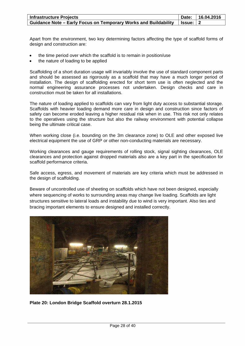
Beware of uncontrolled use of sheeting on scaffolds which have not been designed, especially where sequencing of works to surrounding areas may change live loading. Scaffolds are light structures sensitive to lateral loads and instability due to wind is very important. Also ties and bracing important elements to ensure designed and installed correctly.
Plate 20: London Bridge Scaffold overturn 28.1.2015

Infrastructure Projects Date: 16.04.2016 Guidance Note – Early Focus on Temporary Works and Buildability Issue: 2
Page 29 of 40
Notwithstanding ensuring that “standard” scaffolds are appropriately founded and laterally restrained, “standard” scaffolds should be relatively straightforward. However, care must be given to the design of bespoke scaffolds particularly with respect to connections and overall stability.
27.0 Listed Buildings and Structures
Network Rail owns a significant number of listed buildings and structures. These attract legal requirements and necessitate stakeholder consultation.
When working on listed buildings and structures early consultation with Historic England / English Heritage / Historic Scotland is advised in order to understand the constraints and consultation requirements.
28.0 Communication of Temporary Works Requirements and Design Philosophy
It is important that Temporary Works requirements and their design philosophy are communicated across the many interfaces within projects. Examples of such interfaces include:
Changes of designer such as when a GRIP 3 outline design is taken forward by a different designer
Permanent Works Designer and Temporary Works Designer Temporary Works Designer and Contractor
Permanent Works designs should include clear drawings with significant hazards highlighted on drawings by means of warning triangles or the like.
Temporary Works designs should also include clear drawings with significant hazards highlighted on drawings by means of warning triangles or the like.
Temporary Works Design Risk Assessment information should be clear and relevant to the actual works as opposed to being overly generic.
Temporary Works Design Philosophy and relevant codes (eg: limit state vs permissible stress) should be checked against permanent work philosophy and codes when their interface requires it.
Infrastructure Projects Date: 16.04.2016 Guidance Note – Early Focus on Temporary Works and Buildability Issue: 2
Page 30 of 40
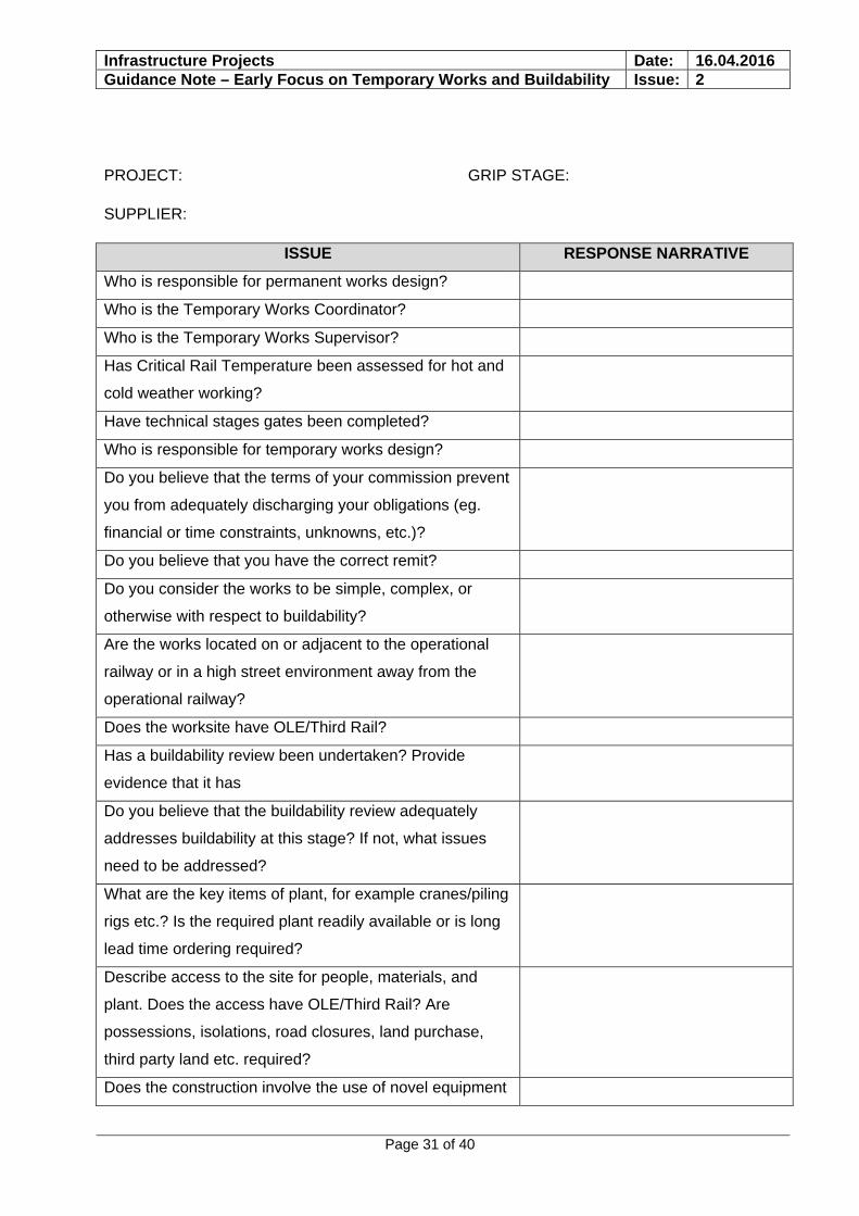
Appendix A: Example of a Buildability Review
Whilst a wide range of projects may have common issues when reviewing buildability it is recognised that every project is unique.
Buildability reviews should be tailored to suit a particular project.
This section includes an example of a buildability review aimed at Network Rail projects in general. This example is intended to suggest the types of issues that may be relevant to buildability reviews, however it is ultimately down to those involved in such a review to select an appropriate agenda:-
Buildability Review
Purpose
Buildability and Temporary Works are issues which sometimes do not get sufficient focus during the design and construction process
Having a clear understanding of these issues, particularly at an early stage of project, is vital to ensuring that there is a robust basis for selecting a single option at GRIP Stage 3 and that the selected option does not carry undue risk impacting safety, programme, cost, rail network performance or otherwise.
Successful management of risk is achieved by managing a number of issues including understanding what we don’t know, complexity, and the environment in which work is being implemented. Enhanced early knowledge of these issues improves our ability to mitigate risk.
The purpose of this review is to provide a framework, or check list, which enhances focus on Buildability and Temporary works throughout the project life cycle. It is not intended to replace or dilute any associated processes or requirements. It is intended that a review is carried out at various GRIP stages
Whilst some of the questions may appear to not be directly related to Buildability and Temporary Works per se, they are aimed at understanding certainty and the potential for change as change itself introduces risk in many ways such programme/cost pressure.
These reviews should be completed to the best of your team’s knowledge. Whilst some questions may “beg” a yes or no answer please give a description if you can. If you don’t know the answer just say so.
Infrastructure Projects Date: 16.04.2016 Guidance Note – Early Focus on Temporary Works and Buildability Issue: 2
Page 31 of 40
PROJECT: GRIP STAGE:
SUPPLIER:
ISSUE RESPONSE NARRATIVE
Who is responsible for permanent works design?
Who is the Temporary Works Coordinator?
Who is the Temporary Works Supervisor?
Has Critical Rail Temperature been assessed for hot and
cold weather working?
Have technical stages gates been completed?
Who is responsible for temporary works design?
Do you believe that the terms of your commission prevent
you from adequately discharging your obligations (eg.
financial or time constraints, unknowns, etc.)?
Do you believe that you have the correct remit?
Do you consider the works to be simple, complex, or
otherwise with respect to buildability?
Are the works located on or adjacent to the operational
railway or in a high street environment away from the
operational railway?
Does the worksite have OLE/Third Rail?
Has a buildability review been undertaken? Provide
evidence that it has
Do you believe that the buildability review adequately
addresses buildability at this stage? If not, what issues
need to be addressed?
What are the key items of plant, for example cranes/piling
rigs etc.? Is the required plant readily available or is long
lead time ordering required?
Describe access to the site for people, materials, and
plant. Does the access have OLE/Third Rail? Are
possessions, isolations, road closures, land purchase,
third party land etc. required?
Does the construction involve the use of novel equipment

Infrastructure Projects Date: 16.04.2016 Guidance Note – Early Focus on Temporary Works and Buildability Issue: 2
Page 32 of 40
ISSUE RESPONSE NARRATIVE
and/or construction techniques? If so do you believe that
these add significant risk to the works?
Is sufficient record data available?
What level of confidence do you have in the available record data?
What surveys are required in order to carry out the
permanent works design?
What surveys are required to carry out the temporary
works design?
Describe how the works interface with the general
public/passengers
Are works to be carried out over the general public and is
protection from dropped loads required?
Are works to be carried out not affecting track or trains.
Are new or increased permanent and/or temporary
utilities required?
Is staging of works and the need for duplicate temporary
facilities understood eg. temporary ticket office, left
luggage, toilets
Are service diversions, temporary duplicate cabling/utility
media required?
Are standard designs being used and if not is there an
opportunity to use them?
Have mock ups, trial erections etc. been considered? Is
there a case for them?
Has the use of modular/prefabricated construction been
optimised?
Assuming that the design is compliant with standards is
there an alternative non compliant design which is a good
engineering solution which would have safety, buildability,
programme, or cost advantages?
Are operation and maintenance properly understood,
particularly from a safety point of view?
Do you believe that further investigation into buildability,

Infrastructure Projects Date: 16.04.2016 Guidance Note – Early Focus on Temporary Works and Buildability Issue: 2
Page 33 of 40
ISSUE RESPONSE NARRATIVE
records, etc. could lead to significant changes to the
permanent works design or to the adoption of a previously
discounted option?
What consultation is likely to be required with neighbours,
planning, English Heritage, other stakeholders?
What impact will the works have on surrounding areas?
eg. Noise, dust, light pollution, possible structural
movement
Will noxious fumes be produced during the works?
Will monitoring be required eg. Structural, air quality,
noise, etc
Does the work involve confined spaces?
Does the work involve paint removal and/or painting. Is
paint to be removed likely to be lead based?
What are the main items of temporary work?
Has working at height been eliminated, minimised or
mitigated against during the design process?
Is there an alternative compliant design which may offer a
safer solution?
Is there a thorough list of temporary works and if so how
“robust” is the list?
Infrastructure Projects Date: 16.04.2016 Guidance Note – Early Focus on Temporary Works and Buildability Issue: 2
Page 34 of 40
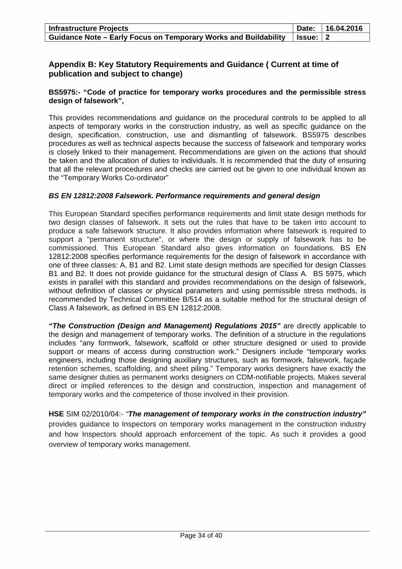
Appendix B: Key Statutory Requirements and Guidance ( Current at time of publication and subject to change)
BS5975:- “Code of practice for temporary works procedures and the permissible stress design of falsework”, This provides recommendations and guidance on the procedural controls to be applied to all aspects of temporary works in the construction industry, as well as specific guidance on the design, specification, construction, use and dismantling of falsework. BS5975 describes procedures as well as technical aspects because the success of falsework and temporary works is closely linked to their management. Recommendations are given on the actions that should be taken and the allocation of duties to individuals. It is recommended that the duty of ensuring that all the relevant procedures and checks are carried out be given to one individual known as the “Temporary Works Co-ordinator”
BS EN 12812:2008 Falsework. Performance requirements and general design
This European Standard specifies performance requirements and limit state design methods for two design classes of falsework. It sets out the rules that have to be taken into account to produce a safe falsework structure. It also provides information where falsework is required to support a "permanent structure", or where the design or supply of falsework has to be commissioned. This European Standard also gives information on foundations. BS EN 12812:2008 specifies performance requirements for the design of falsework in accordance with one of three classes: A, B1 and B2. Limit state design methods are specified for design Classes B1 and B2. It does not provide guidance for the structural design of Class A. BS 5975, which exists in parallel with this standard and provides recommendations on the design of falsework, without definition of classes or physical parameters and using permissible stress methods, is recommended by Technical Committee B/514 as a suitable method for the structural design of Class A falsework, as defined in BS EN 12812:2008.
“The Construction (Design and Management) Regulations 2015” are directly applicable to the design and management of temporary works. The definition of a structure in the regulations includes “any formwork, falsework, scaffold or other structure designed or used to provide support or means of access during construction work.” Designers include “temporary works engineers, including those designing auxiliary structures, such as formwork, falsework, façade retention schemes, scaffolding, and sheet piling.” Temporary works designers have exactly the same designer duties as permanent works designers on CDM-notifiable projects. Makes several direct or implied references to the design and construction, inspection and management of temporary works and the competence of those involved in their provision.
HSE SIM 02/2010/04:- “The management of temporary works in the construction industry” provides guidance to Inspectors on temporary works management in the construction industry and how Inspectors should approach enforcement of the topic. As such it provides a good overview of temporary works management.
Infrastructure Projects Date: 16.04.2016 Guidance Note – Early Focus on Temporary Works and Buildability Issue: 2
Page 35 of 40
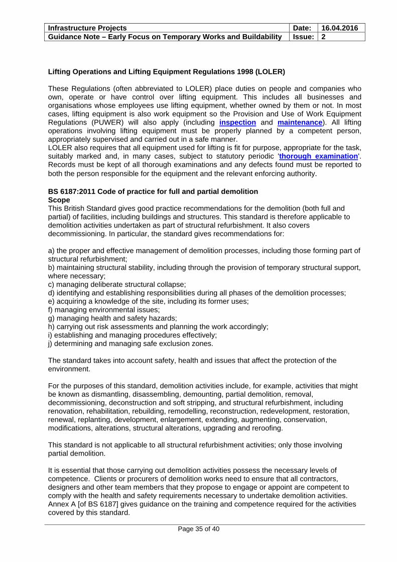
Lifting Operations and Lifting Equipment Regulations 1998 (LOLER) These Regulations (often abbreviated to LOLER) place duties on people and companies who own, operate or have control over lifting equipment. This includes all businesses and organisations whose employees use lifting equipment, whether owned by them or not. In most cases, lifting equipment is also work equipment so the Provision and Use of Work Equipment Regulations (PUWER) will also apply (including inspection and maintenance). All lifting operations involving lifting equipment must be properly planned by a competent person, appropriately supervised and carried out in a safe manner. LOLER also requires that all equipment used for lifting is fit for purpose, appropriate for the task, suitably marked and, in many cases, subject to statutory periodic 'thorough examination'. Records must be kept of all thorough examinations and any defects found must be reported to both the person responsible for the equipment and the relevant enforcing authority. BS 6187:2011 Code of practice for full and partial demolition Scope This British Standard gives good practice recommendations for the demolition (both full and partial) of facilities, including buildings and structures. This standard is therefore applicable to demolition activities undertaken as part of structural refurbishment. It also covers decommissioning. In particular, the standard gives recommendations for: a) the proper and effective management of demolition processes, including those forming part of structural refurbishment; b) maintaining structural stability, including through the provision of temporary structural support, where necessary; c) managing deliberate structural collapse; d) identifying and establishing responsibilities during all phases of the demolition processes; e) acquiring a knowledge of the site, including its former uses; f) managing environmental issues; g) managing health and safety hazards; h) carrying out risk assessments and planning the work accordingly; i) establishing and managing procedures effectively; j) determining and managing safe exclusion zones. The standard takes into account safety, health and issues that affect the protection of the environment. For the purposes of this standard, demolition activities include, for example, activities that might be known as dismantling, disassembling, demounting, partial demolition, removal, decommissioning, deconstruction and soft stripping, and structural refurbishment, including renovation, rehabilitation, rebuilding, remodelling, reconstruction, redevelopment, restoration, renewal, replanting, development, enlargement, extending, augmenting, conservation, modifications, alterations, structural alterations, upgrading and reroofing. This standard is not applicable to all structural refurbishment activities; only those involving partial demolition. It is essential that those carrying out demolition activities possess the necessary levels of competence. Clients or procurers of demolition works need to ensure that all contractors, designers and other team members that they propose to engage or appoint are competent to comply with the health and safety requirements necessary to undertake demolition activities. Annex A [of BS 6187] gives guidance on the training and competence required for the activities covered by this standard.

Infrastructure Projects Date: 16.04.2016 Guidance Note – Early Focus on Temporary Works and Buildability Issue: 2
Page 36 of 40
PAS 8811 Code of practice for temporary works – Client procedures (Due to be published in 2016) This PAS gives recommendations on client procedures for temporary works. It covers processes, roles, responsibilities and competences, and provides example pro forma documentation. The aim of this PAS is to establish a unified approach to client involvement in temporary works across all stages (e.g. defining requirements, procurement, installation, use and removal of temporary works structures) and eliminate unnecessary procedures and conflicts in order to achieve clarity and minimize delays during compliance and approvals processes and other necessary procedures with respect to temporary works. This PAS is designed to complement BS 5975, Code of practice for temporary works and permissible stress design of falsework with the same aim of controlling risk and ensuring adequate procedures. It concentrates on client activities which are not covered by BS 5975. This PAS does not cover the contractual responsibilities of clients, suppliers or contractors. Where there are relevant existing standards or industry documents, this PAS refers to these. It is not the intention of this PAS to replicate existing material. PAS 8812:2015 Guide to the application of European Standards in temporary works design This PAS gives guidance on the application of European Standards in the design of temporary works in the UK. It covers: a) interpretation of key design approaches applicable to all temporary works including:
1) relationship between Eurocodes and the temporary works suite of European Standards; 2) recommendations on suitable partial factors and combinations of actions; 3) recommendations on appropriate analysis approach; 4) stability considerations; 5) considerations on reuse of equipment;
b) clarification of design requirements for identified groups of temporary works. This PAS has been designed to facilitate consistency in the design approach to temporary works and remove the uncertainties for temporary works designers.
Infrastructure Projects Date: 16.04.2016 Guidance Note – Early Focus on Temporary Works and Buildability Issue: 2
Page 37 of 40
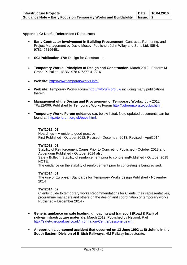
Appendix C: Useful References / Resources
Early Contractor Involvement in Building Procurement: Contracts, Partnering, and Project Management by David Mosey. Publisher: John Wiley and Sons Ltd. ISBN: 9781405196451
SCI Publication 178: Design for Construction
Temporary Works: Principles of Design and Construction. March 2012. Editors: M. Grant; P. Pallett. ISBN: 978-0-7277-4177-6
Website: http://www.temporaryworks.info/
Website: Temporary Works Forum http://twforum.org.uk/ including many publications
therein.
Management of the Design and Procurement of Temporary Works. July 2012. TW/12/006. Published by Temporary Works Forum http://twforum.org.uk/pubs.html.
Temporary Works Forum guidance e.g. below listed. Note updated documents can be
found at: http://twforum.org.uk/pubs.html.
TWf2012: 01 Hoardings – A guide to good practice First Published - October 2012; Revised - December 2013; Revised - April2014 TWf2013: 01 Stability of Reinforcement Cages Prior to Concreting Published - October 2013 and Addendum Published - October 2014 also Safety Bulletin: Stability of reinforcement prior to concretingPublished - October 2015 NOTE: The guidance on the stability of reinforcement prior to concreting is beingrevised. TWf2014: 01 The use of European Standards for Temporary Works design Published - November 2014 TWf2014: 02 Clients’ guide to temporary works Recommendations for Clients, their representatives, programme managers and others on the design and coordination of temporary works Published – December 2014 -
Generic guidance on safe loading, unloading and transport (Road & Rail) of railway infrastructure materials. March 2012. Published by Network Rail http://safety.networkrail.co.uk/Information-Centre/Lessons-Learnt.
A report on a personnel accident that occurred on 13 June 1992 at St John’s in the
South Eastern Division of British Railways. HM Railway Inspectorate.
Infrastructure Projects Date: 16.04.2016 Guidance Note – Early Focus on Temporary Works and Buildability Issue: 2
Page 38 of 40
BS 6187:2011 Code of practice for full and partial demolition. British Standards
Online (BSOL). https://bsol.bsigroup.com
HSE Temporary Works Managment http://www.hse.gov.uk/scotland/temporary-works-management.pdf
PAS 8811 Code of practice for temporary works – Client procedures
PAS 8812:2015 Guide to the application of European Standards in temporary works design
National Access and Scaffolding Confederation publications including (but not limited to)
SG4.15 Preventing falls in scaffolding operations.
TG20:13, Guide to good practice for tube and fitting scaffolding,
BS5975:- “Code of practice for temporary works procedures and the permissible
stress design of falsework”,
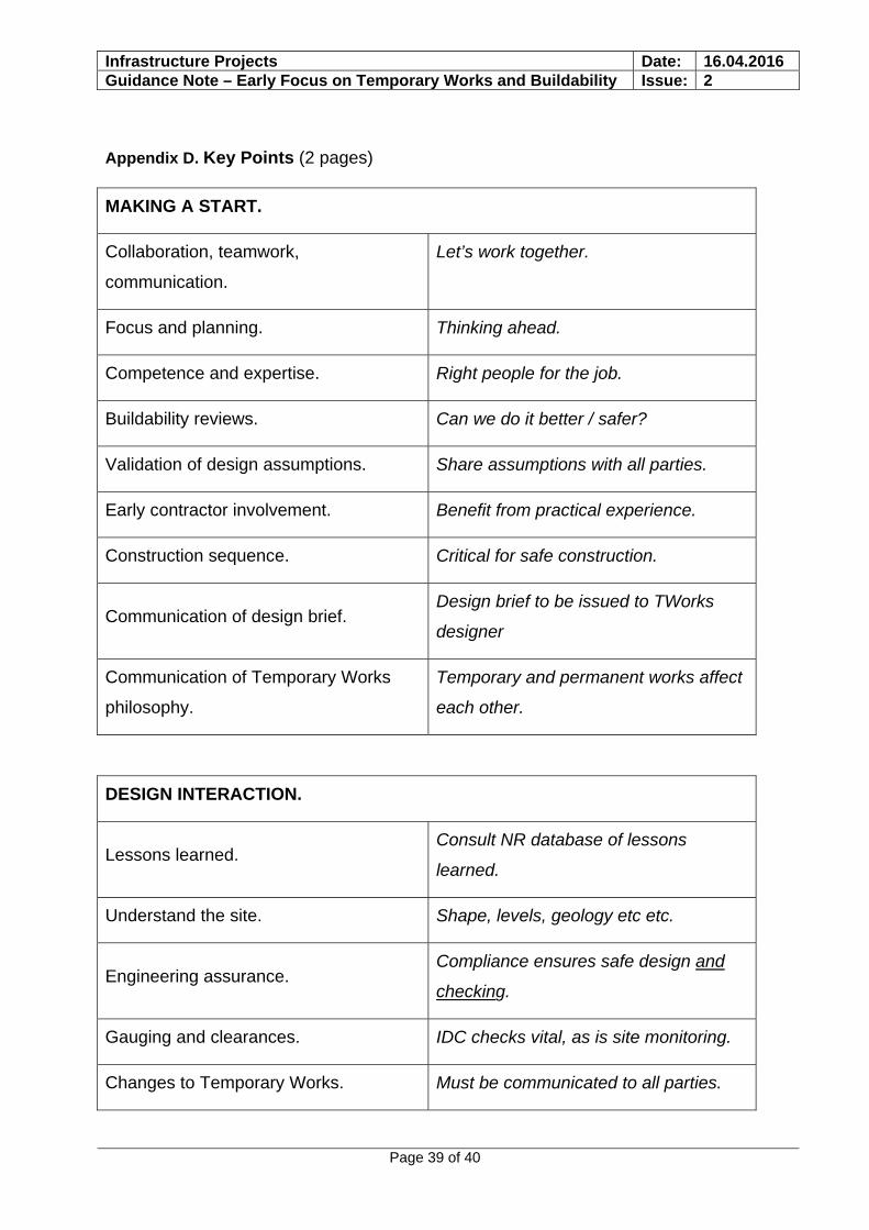
Infrastructure Projects Date: 16.04.2016 Guidance Note – Early Focus on Temporary Works and Buildability Issue: 2
Page 39 of 40
Appendix D. Key Points (2 pages)
MAKING A START.
Collaboration, teamwork,
communication.
Let’s work together.
Focus and planning. Thinking ahead.
Competence and expertise. Right people for the job.
Buildability reviews. Can we do it better / safer?
Validation of design assumptions. Share assumptions with all parties.
Early contractor involvement. Benefit from practical experience.
Construction sequence. Critical for safe construction.
Communication of design brief. Design brief to be issued to TWorks
designer
Communication of Temporary Works
philosophy.
Temporary and permanent works affect
each other.
DESIGN INTERACTION.
Lessons learned. Consult NR database of lessons
learned.
Understand the site. Shape, levels, geology etc etc.
Engineering assurance. Compliance ensures safe design and
checking.
Gauging and clearances. IDC checks vital, as is site monitoring.
Changes to Temporary Works. Must be communicated to all parties.
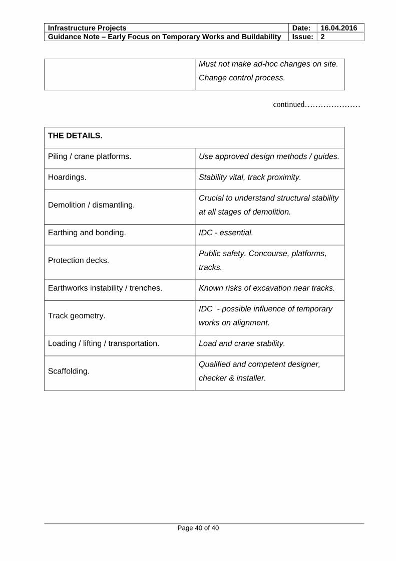
Infrastructure Projects Date: 16.04.2016 Guidance Note – Early Focus on Temporary Works and Buildability Issue: 2
Page 40 of 40
Must not make ad-hoc changes on site.
Change control process.
continued…………………
THE DETAILS.
Piling / crane platforms. Use approved design methods / guides.
Hoardings. Stability vital, track proximity.
Demolition / dismantling. Crucial to understand structural stability
at all stages of demolition.
Earthing and bonding. IDC - essential.
Protection decks. Public safety. Concourse, platforms,
tracks.
Earthworks instability / trenches. Known risks of excavation near tracks.
Track geometry. IDC - possible influence of temporary
works on alignment.
Loading / lifting / transportation. Load and crane stability.
Scaffolding. Qualified and competent designer,
checker & installer.