earth coordinates - clynchg3c.comclynchg3c.com/technote/geodesy/coorddef.pdf · 1 earth coordinates...
TRANSCRIPT

1
Earth CoordinatesJames R. ClynchFebruary 2006
I. Coordinate Types
There are two generic types of coordinates:
Cartesian, andCurvilinear of Angular.
Those that provide x-y-z type values in meters, kilometers or other distance units are calledCartesian. Those that provide latitude, longitude, and height are called curvilinear or angular.
The Cartesian and angular coordinates are equivalent, but only after supplying some extrainformation. For the spherical earth model only the earth radius is needed. For the ellipsoidalearth, two parameters of the ellipsoid are needed. (These can be any of several sets. The mostcommon is the semi-major axis, called "a", and the flattening, called "f".)
II. Cartesian Coordinates
A. Generic Cartesian Coordinates
These are the coordinates that are used in algebra to plot functions. For a twodimensional system there are two axes, which are perpendicular to each other. The value of apoint is represented by the values of the point projected onto the axes. In the figure below thepoint (5,2) and the standard orientation for the X and Y axes are shown.
2
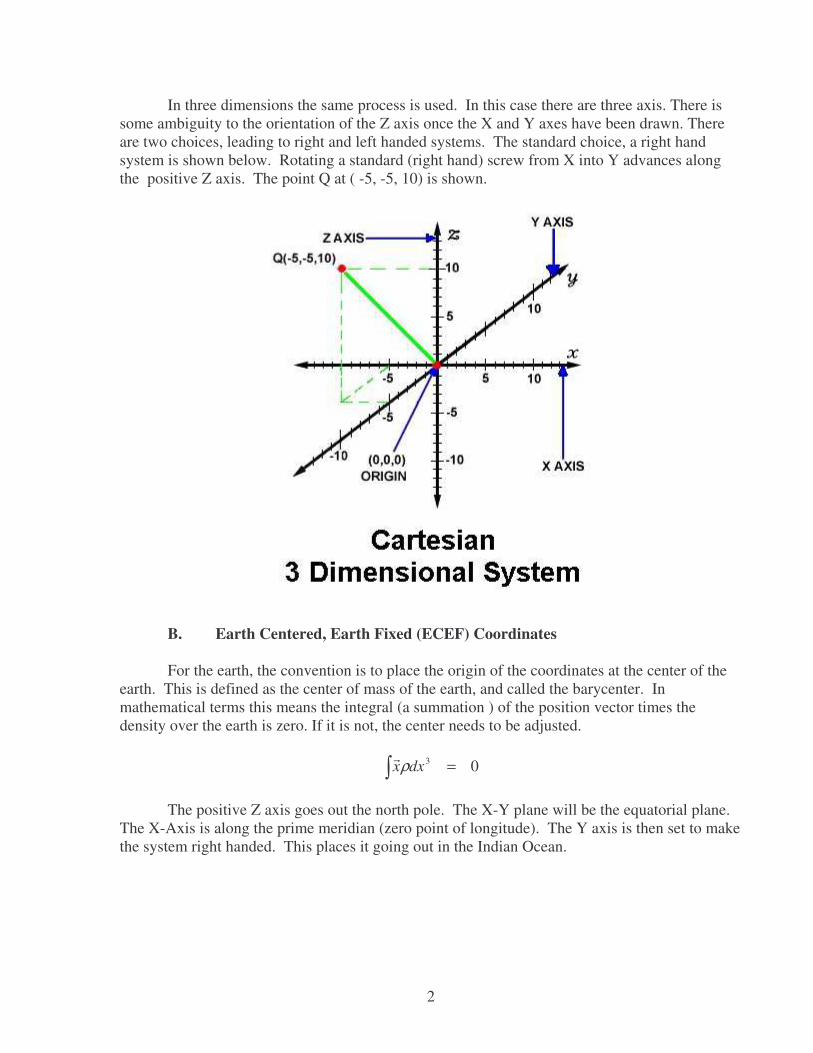
In three dimensions the same process is used. In this case there are three axis. There issome ambiguity to the orientation of the Z axis once the X and Y axes have been drawn. Thereare two choices, leading to right and left handed systems. The standard choice, a right handsystem is shown below. Rotating a standard (right hand) screw from X into Y advances alongthe positive Z axis. The point Q at ( -5, -5, 10) is shown.
B. Earth Centered, Earth Fixed (ECEF) Coordinates
For the earth, the convention is to place the origin of the coordinates at the center of theearth. This is defined as the center of mass of the earth, and called the barycenter. Inmathematical terms this means the integral (a summation ) of the position vector times thedensity over the earth is zero. If it is not, the center needs to be adjusted.
� = 03dxxρ�
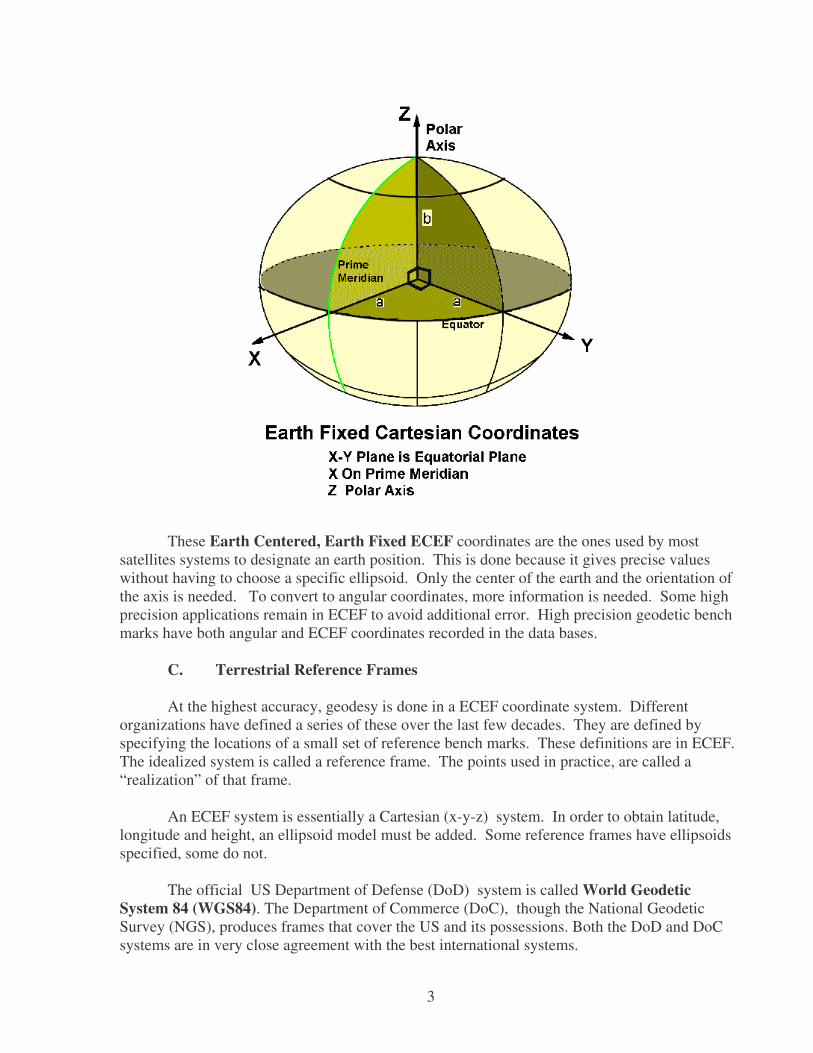
The positive Z axis goes out the north pole. The X-Y plane will be the equatorial plane.The X-Axis is along the prime meridian (zero point of longitude). The Y axis is then set to makethe system right handed. This places it going out in the Indian Ocean.
3
These Earth Centered, Earth Fixed ECEF coordinates are the ones used by mostsatellites systems to designate an earth position. This is done because it gives precise valueswithout having to choose a specific ellipsoid. Only the center of the earth and the orientation ofthe axis is needed. To convert to angular coordinates, more information is needed. Some highprecision applications remain in ECEF to avoid additional error. High precision geodetic benchmarks have both angular and ECEF coordinates recorded in the data bases.
C. Terrestrial Reference Frames
At the highest accuracy, geodesy is done in a ECEF coordinate system. Differentorganizations have defined a series of these over the last few decades. They are defined byspecifying the locations of a small set of reference bench marks. These definitions are in ECEF.The idealized system is called a reference frame. The points used in practice, are called a“realization” of that frame.
An ECEF system is essentially a Cartesian (x-y-z) system. In order to obtain latitude,longitude and height, an ellipsoid model must be added. Some reference frames have ellipsoidsspecified, some do not.
The official US Department of Defense (DoD) system is called World GeodeticSystem 84 (WGS84). The Department of Commerce (DoC), though the National GeodeticSurvey (NGS), produces frames that cover the US and its possessions. Both the DoD and DoCsystems are in very close agreement with the best international systems.

4
The WGS84 World Geodetic System has several components. One of these componentsis the reference frame. WGS84 is the basis of the GPS solutions. This was done by finding theWGS84 ECEF locations of the stations that supply data for the Broad Cast Ephemeris (BCE)computation. It is also used in the DoD precise ephemeris computation. WGS84 was a majorsuccessor to the previous system WGS72. There was a significant shift between the two systemsin some parts of the world.
WGS84 has been periodically updated. The new systems are labeled WGS84 (Gnnn)where nnn is a GPS week number. This is the time when the update was placed into effect byusing new station coordinates for the GPS ground reference stations. There have been threeupdates so far, G730, G873, and G1150. The latest, WGS(G1150)2 took effect 1 October 2004.
The science community has been working on a series of world reference systems that arecalled International Terrestrial Reference Systems or ITRF's. The earliest ones wereITRF92 and ITRF94, which was quite good. Modest improvements followed with ITRF97 andITRF2000. The later two models were so accurate that models of the motion of the crustalplates of the earth had to be included. The updates to WGS84 have brought the WGS84 systeminto alignment with these ITRF systems. Currently (2006) the difference between the latestWGS84 and latest ITRF are only a few cm.
III. Angular or Curvilinear Coordinates
Angular coordinates or curvilinear coordinates are the latitude, longitude and heightthat are common on maps and in everyday use. The conversion is simple for the spherical earthmodel. For the ellipsoidal model, which is needed for real world applications, the issue oflatitude is more complex. The height is even more complicated.
A. Latitude and Longitude on Spherical Earth
Latitude and longitude are the grid lines you see on globes. For a spherical earththese are angles seen from the center of the earth. The angle up from the equator is latitude. Inthe southern hemisphere it is negative in geodesy. Latitude has a range of –90 degrees to 90degrees in this convention. The reference for latitude is set by the equator - effectively set by thespin axis of the earth.
The angle in the equatorial plane is the longitude. There is no natural reference forlongitude. The zero line, called the prime meridian, is taken, by convention, as the line throughGreenwich England. (This was set by treaty in 1878. Before that each major nation had its ownzero of longitude.)
2 Addendum to NIMA TR 8350.2: Implementation of the World Geodetic System 1984 (WGS84) Reference Frame G1150.
5
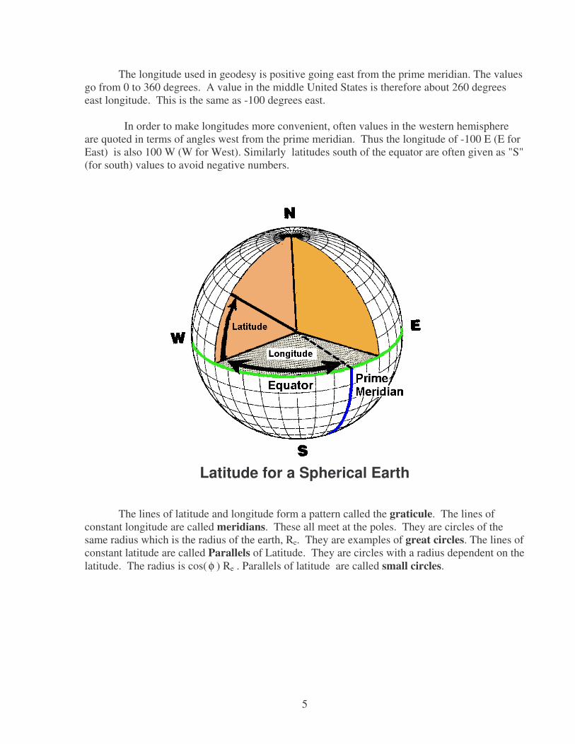
The longitude used in geodesy is positive going east from the prime meridian. The valuesgo from 0 to 360 degrees. A value in the middle United States is therefore about 260 degreeseast longitude. This is the same as -100 degrees east.
In order to make longitudes more convenient, often values in the western hemisphereare quoted in terms of angles west from the prime meridian. Thus the longitude of -100 E (E forEast) is also 100 W (W for West). Similarly latitudes south of the equator are often given as "S"(for south) values to avoid negative numbers.
Latitude for a Spherical Earth
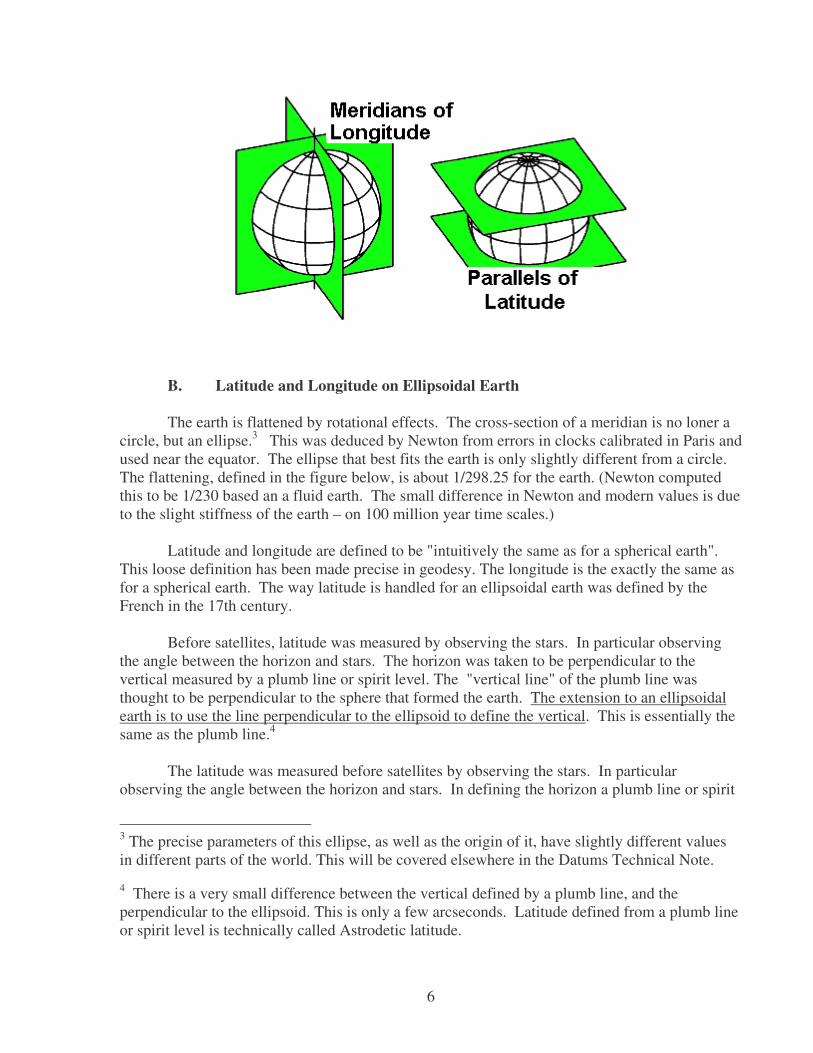
The lines of latitude and longitude form a pattern called the graticule. The lines ofconstant longitude are called meridians. These all meet at the poles. They are circles of thesame radius which is the radius of the earth, Re. They are examples of great circles. The lines ofconstant latitude are called Parallels of Latitude. They are circles with a radius dependent on thelatitude. The radius is cos( φ ) Re . Parallels of latitude are called small circles.
6
B. Latitude and Longitude on Ellipsoidal Earth
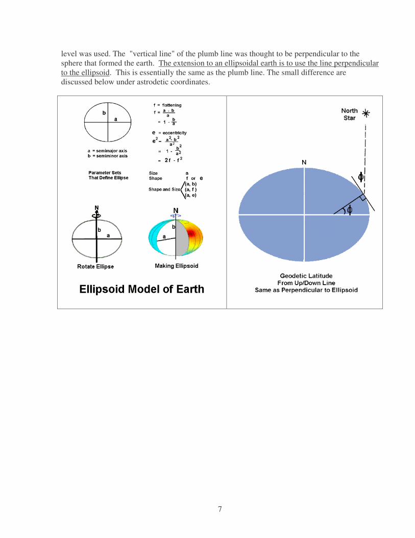
The earth is flattened by rotational effects. The cross-section of a meridian is no loner acircle, but an ellipse.3 This was deduced by Newton from errors in clocks calibrated in Paris andused near the equator. The ellipse that best fits the earth is only slightly different from a circle.The flattening, defined in the figure below, is about 1/298.25 for the earth. (Newton computedthis to be 1/230 based an a fluid earth. The small difference in Newton and modern values is dueto the slight stiffness of the earth – on 100 million year time scales.)
Latitude and longitude are defined to be "intuitively the same as for a spherical earth".This loose definition has been made precise in geodesy. The longitude is the exactly the same asfor a spherical earth. The way latitude is handled for an ellipsoidal earth was defined by theFrench in the 17th century.
Before satellites, latitude was measured by observing the stars. In particular observingthe angle between the horizon and stars. The horizon was taken to be perpendicular to thevertical measured by a plumb line or spirit level. The "vertical line" of the plumb line wasthought to be perpendicular to the sphere that formed the earth. The extension to an ellipsoidalearth is to use the line perpendicular to the ellipsoid to define the vertical. This is essentially thesame as the plumb line.4
The latitude was measured before satellites by observing the stars. In particularobserving the angle between the horizon and stars. In defining the horizon a plumb line or spirit
3 The precise parameters of this ellipse, as well as the origin of it, have slightly different valuesin different parts of the world. This will be covered elsewhere in the Datums Technical Note.
4 There is a very small difference between the vertical defined by a plumb line, and theperpendicular to the ellipsoid. This is only a few arcseconds. Latitude defined from a plumb lineor spirit level is technically called Astrodetic latitude.
7
level was used. The "vertical line" of the plumb line was thought to be perpendicular to thesphere that formed the earth. The extension to an ellipsoidal earth is to use the line perpendicularto the ellipsoid. This is essentially the same as the plumb line. The small difference arediscussed below under astrodetic coordinates.

8
The figure below shows the key effects of rotation on the earth and coordinates. Thelatitude is defined in both the spherical and ellipsoidal cases from the line perpendicular to theworld model. In the case of the spherical earth, this line hits the origin of the sphere - the centerof the earth. For the ellipsoidal model the up-down line does not hit the center of the earth. Itdoes hit the polar axis though.
The length of the line to the center of the earth for a spherical model is the radius of thesphere. For the ellipsoidal model the length from the surface to the polar axis is one of threeradii needed to work with angles and distance on the earth. (It is called the radius of curvaturein the prime vertical, and denoted RN here. See the document on radii of the earth for details.)
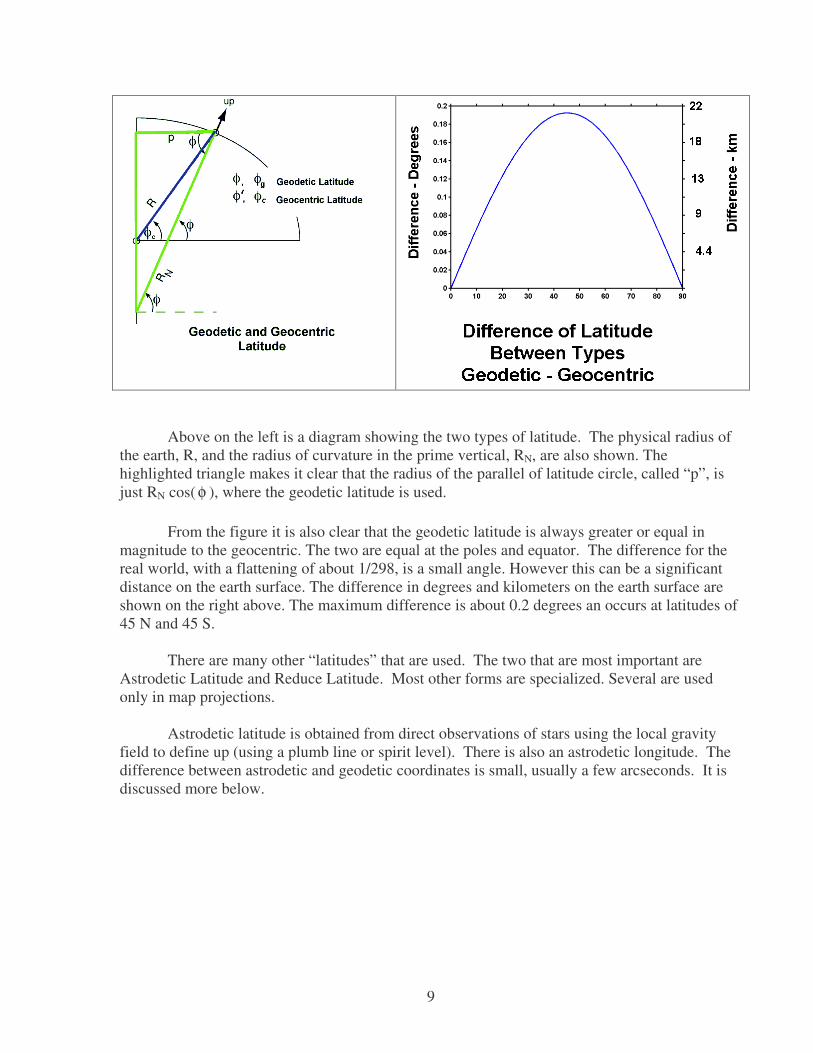
There are not two types of latitude that can easily be defined. The angle that the linemakes from the center of the earth is called the geocentric latitude. Geocentric latitude isusually denoted as cor, φφ′ . It does not strike the surface of the ellipsoid at a right angle. Theline perpendicular to the ellipsoid makes an angle with the equatorial plane that is called thegeodetic latitude. ("Geodetic" is usually implies something taken with respect to the ellipsoid.)The latitude on maps is geodetic latitude. It is usually denoted as gor, φφ
9
Above on the left is a diagram showing the two types of latitude. The physical radius ofthe earth, R, and the radius of curvature in the prime vertical, RN, are also shown. Thehighlighted triangle makes it clear that the radius of the parallel of latitude circle, called “p”, isjust RN cos( φ ), where the geodetic latitude is used.
From the figure it is also clear that the geodetic latitude is always greater or equal inmagnitude to the geocentric. The two are equal at the poles and equator. The difference for thereal world, with a flattening of about 1/298, is a small angle. However this can be a significantdistance on the earth surface. The difference in degrees and kilometers on the earth surface areshown on the right above. The maximum difference is about 0.2 degrees an occurs at latitudes of45 N and 45 S.
There are many other “latitudes” that are used. The two that are most important areAstrodetic Latitude and Reduce Latitude. Most other forms are specialized. Several are usedonly in map projections.
Astrodetic latitude is obtained from direct observations of stars using the local gravityfield to define up (using a plumb line or spirit level). There is also an astrodetic longitude. Thedifference between astrodetic and geodetic coordinates is small, usually a few arcseconds. It isdiscussed more below.

10
Reduced latitude, usually denoted by β in geodesy, is an angle from the center of the earth to acircle that has the semi-major axis length. This is called the circumscribing circle. The reducelatitude angle between the equator and a point on the circumscribing circle. This point is along aline parallel to the Z axis and through the point. The reduce latitude is used in theoreticalgravity studies where it forms part of the ellipsoidal coordinate system This angle is important inorbit work. There it is called the Eccentric Anomaly and denoted by “E”.
C. Heights
Rather than define the radial distance from the center of the earth for a point, it is moreconvenient to define the height. The question is what is the reference surface. For the sphericalearth model, the answer is simple, the sphere with the radius of the mean earth is the reference.
For the ellipsoidal model of the earth, the ellipsoid can be used as the reference surface.This is done and the resulting height is called ellipsoidal height or geodetic height. But this isnot the height found on maps.
For practical purposes the height used on maps is mean sea level (MSL) heights. It hasthe official name of orthometric height. It is measured by going from point to point inlandfrom points near the sea where mean sea level is determined by tide gauges. This is the heighton maps.
One might assume that geodetic (ellipsoidal) height and MSL height would just bedifferent by some constant that is the error in the tide gauge calibration. But this is not the case.The sea is not "flat", that is it is not an ellipsoid. The true gravity field of the earth is lumpy.Just as the up direction is perpendicular to the ellipsoid in the homogeneous earth case, for thereal earth up is perpendicular to the geoid.
11
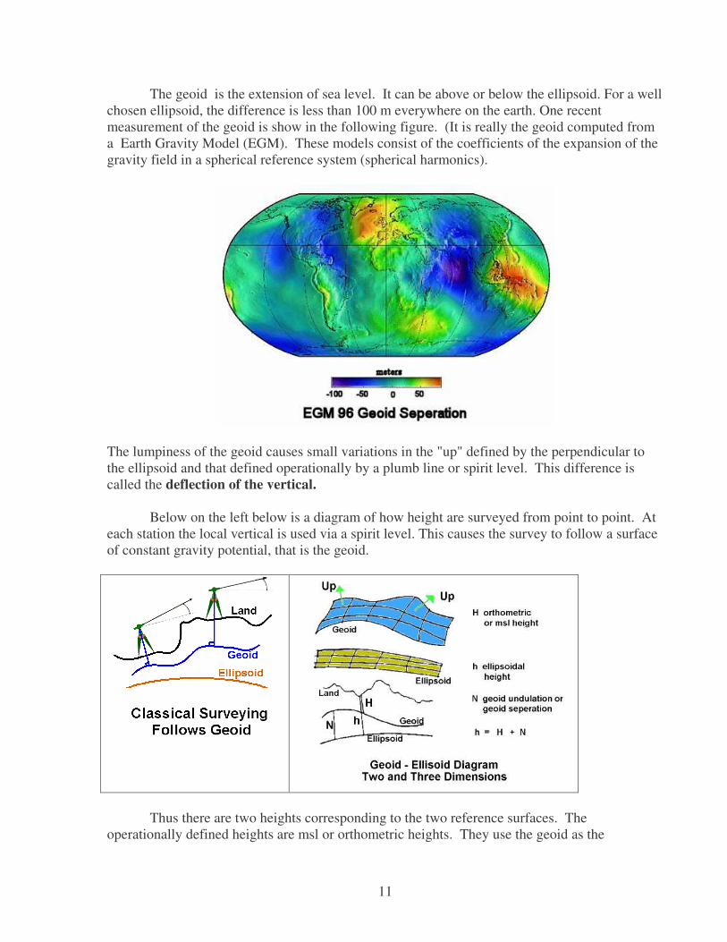
The geoid is the extension of sea level. It can be above or below the ellipsoid. For a wellchosen ellipsoid, the difference is less than 100 m everywhere on the earth. One recentmeasurement of the geoid is show in the following figure. (It is really the geoid computed froma Earth Gravity Model (EGM). These models consist of the coefficients of the expansion of thegravity field in a spherical reference system (spherical harmonics).
The lumpiness of the geoid causes small variations in the "up" defined by the perpendicular tothe ellipsoid and that defined operationally by a plumb line or spirit level. This difference iscalled the deflection of the vertical.
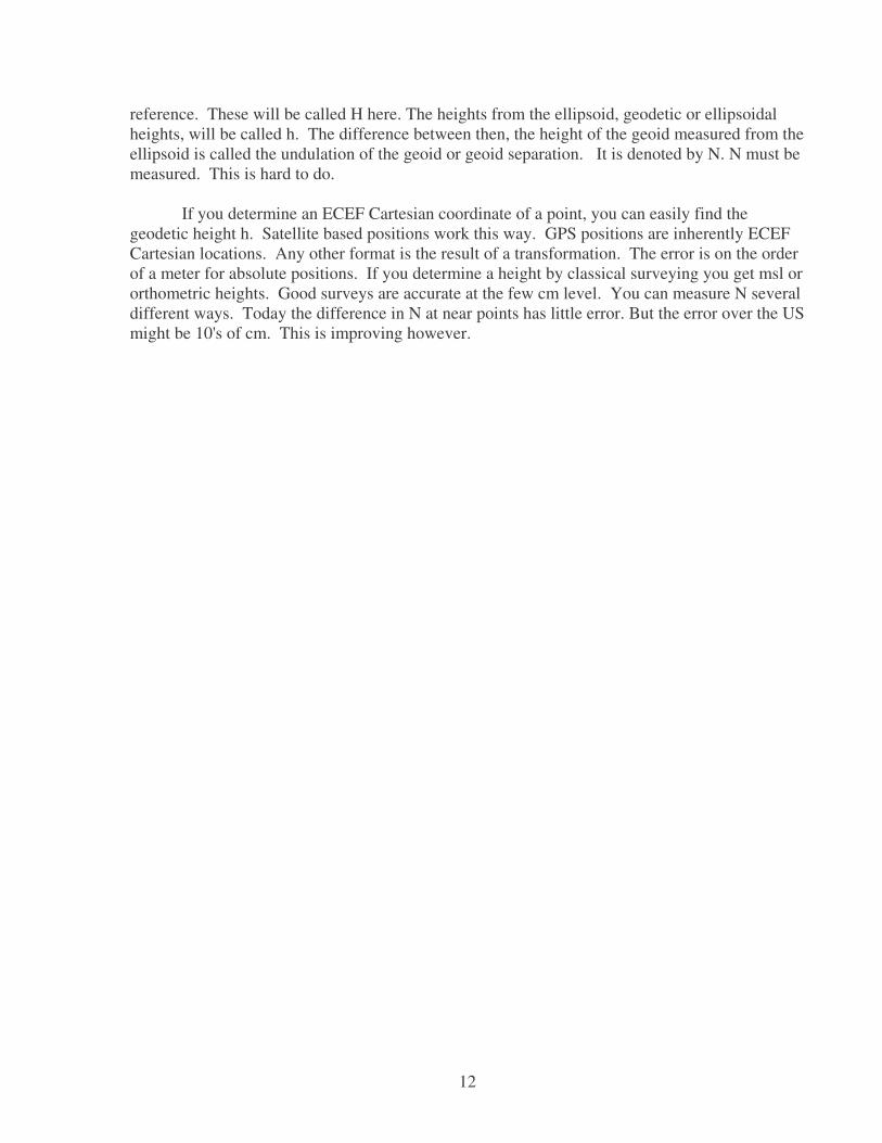
Below on the left below is a diagram of how height are surveyed from point to point. Ateach station the local vertical is used via a spirit level. This causes the survey to follow a surfaceof constant gravity potential, that is the geoid.
Thus there are two heights corresponding to the two reference surfaces. Theoperationally defined heights are msl or orthometric heights. They use the geoid as the
12
reference. These will be called H here. The heights from the ellipsoid, geodetic or ellipsoidalheights, will be called h. The difference between then, the height of the geoid measured from theellipsoid is called the undulation of the geoid or geoid separation. It is denoted by N. N must bemeasured. This is hard to do.
If you determine an ECEF Cartesian coordinate of a point, you can easily find thegeodetic height h. Satellite based positions work this way. GPS positions are inherently ECEFCartesian locations. Any other format is the result of a transformation. The error is on the orderof a meter for absolute positions. If you determine a height by classical surveying you get msl ororthometric heights. Good surveys are accurate at the few cm level. You can measure N severaldifferent ways. Today the difference in N at near points has little error. But the error over the USmight be 10's of cm. This is improving however.

13
D. SUMMARY of MODELS AND ANGULAR COORDINATE TYPES
E. Angular to/from Cartesian
There is a detailed separate document on the transformation between these two types ofcoordinates. It will not be repeated here. The key issue is what information is needed.
Spherical Model: ECEF to Longitude No additional information needed ECEF to Latitude No additional information needed ECEF to height Radius of Earth needed Latitude, longitude, height to ECEF Radius of EarthEllipsoidal Model: ECEF to Longitude No additional information needed ECEF to Latitude Ellipsoid parameter e ( or f ) ECEF to ellipsoidal height Ellipsoid parameters ( a, f)Ellipsoid height to MSL height Geoid separation ( undulation ) NLatitude, Longitude, Ellipsoidal height to ECEF Ellipsoid parameters ( a, f )
5 Note: Level surfaces are surfaces of constant gravity potential. This is the potential energyper unit mass of something rotating with the earth. The sea is one level surface. (If we ignoresome small effects due to ocean currents.) The up-down line as measured by a plumb line orspirit level is always perpendicular to a level surface. The geoid is the level surface thatrepresents mean sea level, but is also extended over the entire earth. It is usually under the land.
MODEL Surface LatitudeLongitude
Height
Spherical/GlobeUsed in elementarydescriptions
Sphere Geocentric spherical
Ellipsoid/EllipsoidalUsed in mapmaking
Ellipse ofRevolution
GeodeticUsed on maps
ellipsoidalProduced bySatellite Systems(GPS etc.)
Real World GeoidA Level5
Surface
Astrodetic orAstronomic
Orthometric(Mean Sea Level)Used on maps
14
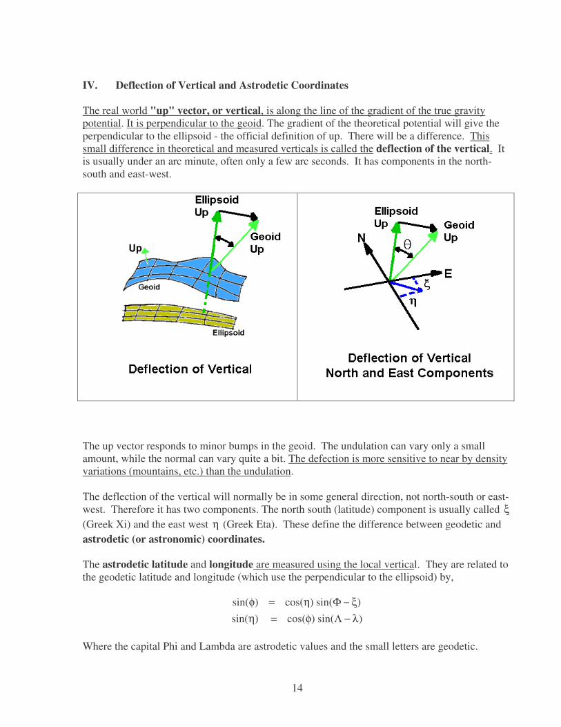
IV. Deflection of Vertical and Astrodetic Coordinates
The real world "up" vector, or vertical, is along the line of the gradient of the true gravitypotential. It is perpendicular to the geoid. The gradient of the theoretical potential will give theperpendicular to the ellipsoid - the official definition of up. There will be a difference. Thissmall difference in theoretical and measured verticals is called the deflection of the vertical. Itis usually under an arc minute, often only a few arc seconds. It has components in the north-south and east-west.
The up vector responds to minor bumps in the geoid. The undulation can vary only a smallamount, while the normal can vary quite a bit. The defection is more sensitive to near by densityvariations (mountains, etc.) than the undulation.
The deflection of the vertical will normally be in some general direction, not north-south or east-west. Therefore it has two components. The north south (latitude) component is usually called ξ(Greek Xi) and the east west η (Greek Eta). These define the difference between geodetic andastrodetic (or astronomic) coordinates.
The astrodetic latitude and longitude are measured using the local vertical. They are related tothe geodetic latitude and longitude (which use the perpendicular to the ellipsoid) by,
)sin()cos()sin()sin()cos()sin(
λ−Λφ=ηξ−Φη=φ
Where the capital Phi and Lambda are astrodetic values and the small letters are geodetic.
15
Because the deflection is small, cos( η) can be taken as 1 and sin( ξ ) as ξ . Then
)cos()(),(
φλ−Λ=ηφ−Φ=ξ
V. Earth Reference Systems and Satellites
A. Earth and Sky Connections - Irregular Earth Motion
In dealing with earth based surveying and coordinates you can just drive a stake in theearth, call it the primary reference point and go from there. But if you want to connect to thesky, to the stars, to an inertial reference system you need more. Any time you deal withsatellites, you are dealing with this inertial space, a non-rotating system. The facts may behidden from you, as is done in GPS, but they are used somewhere.
In inertial space, satellites go in nice, repeating ellipses (almost), but the ground tracksare complicated. For geostationary satellites, the ground track would be a point in theory. A polarorbiting satellite at 1200 km altitude makes a revolution in about 100 minutes. To the satellite itmakes regular repeatable orbits and the earth rotates underneath it. However, the ground track isa set of curved lines.
The big complication comes in connecting inertial space to earth coordinates. Theproblem is the non-uniform motion of the earth. Not only does the earth go around the sun at avarying speed, faster in January when the earth is a little closer to the sun and slower in July, butthere an many smaller motions. The polar axis is not fixed in inertial space. It moves in a circlewith period of 26,000 years. The rotation axis points almost at the star Polaris now, but in 14,000years will point at Vega. This is called the precision or precision of the equinox. In additionthere is a smaller oscillation with a period of 18.6 years due to the moon. This is callednutation. These are smooth and predictable. But there are smaller, unpredictable motions.These are called the polar motion.
The polar motion has an irregular circular motion with a period of about 1.3 years. If onetakes the average of these revolutions, then it is clear that even that center location is walking.This is evident in the following graph adapted from the International Earth Rotation Service(IERS). Before satellite techniques were available, only long period averages were measurablewith any accuracy. Today daily positions are computed by several groups and assembled by theIERS.
For reference, an arc-second measured from the center of the earth represents a distanceof about 30 m. Therefore the diameter of these recent 1.3 year tracks is about 15 m.

16
In addition to the motion of the spin axis, the rate of spin of the earth is variable. Thishas been known for two centuries. Today the IERS also determines this from measurements andpublishes the offset of a clock based on the earth rotation (called Universal Time 1 or UT1) anda "perfect" atomic clock (called UT or UTA). Universal Time Coordinated (UTC) is UTAwith occasional jumps of 1 second (leap seconds) to keep it within 0.9 sec. of UT1.
The UT1 minus UT difference represents the integrated effect of small variations in theearth spin. A plot of the difference is shown below. Notice that several seconds of change haveoccurred, that the changes are increasing and decreasing over time, and that lately the rate hasbeen running consistently lower.
17
Unfortunately, in order to find spacecraft positions at high accuracy, computations mustbe done in an inertial frame and uniform time frame (UTA). Thus measurements are made,usually from earth, and adjusted to an inertial frame. The orbit is computed in this frame. Theresults must then be adjusted to earth fixed coordinates in some specific datum. This mustinclude all the smooth (precession and nutation) effects as well as irregular effects of the earth'smotion.
For the Global Positioning System this is all done at the central processing center. Amodel of the satellite motion in earth fixed coordinates is produced and broadcast to the user.The difficult work must be done, but it is done once for all the users of the broadcast ephemeris(BCE).
B. Celestial Reference Frames
Prior to the 1960's stars were the only "points of reference" that could be used as benchmarks for a celestial reference system. There were a series of catalogues of star positions usedjust like bench marks for realizing the celestial coordinate system These were called theFundamental Katalog (in German) and the systems were know as FK1, FK2 etc. The last such"celestial" datum was FK5 J2000.5 . The date implies that the precision and nutation were usedto adjust the coordinates to how they would be seen in the middle of year 2000. The locationswere coupled to the motions of the earth.
In addition stars move. The apparent positions of stars have small, but measurablechanges. These are called proper motions. They are only important for nearby stars, but thoseare generally the brightest stars and the most important in establishing the celestial referenceframes. This meant that another factor would have to be included in the definitions.
Beginning in the 1960's radio astronomy began to use antennas separated by distances upto the diameter of the earth to form an effective single large antenna. This is called Very LongBaseline Interferometry (VLBI). The angular resolution was extremely small. It was muchsmaller than could be achieved with optical telescopes on a practical basis. Thus there wereseparate celestial reference system for optical and radio astronomy.
In 1998 a new system was accepted by the International Astronomic Union that wasbased on point like radio sources outside the galaxy. This united the two systems and decoupledthe reference system for inertial space measurements from models of the earth's motion.
C. ICRS and ICRF
The International Celestial Reference System (ICRS) is similar to the mathematicaldefinition of a datum. It is the idealized reference frame. In this case it has some substance inthe extragalactic radio sources. One particular source, 3C 273B has adopted, fixed coordinatesthat define the system. The IAU adopted this to replace FK5 in 1998. There are 23 extragalacticsources that are used to form the primary reference system. These have all been connected withVLBI measurements.

18
The International Celestial Reference Frame (ICRF) is analogous to the realization ofa datum. It has measured coordinates of 212 extragalactic sources that form the first ordernetwork. (Some workers use 608 radio sources.) Each of these is measured with respect toseveral of the 23 primary sources.
In addition this system has been connected to new, very accurate star catalogues.Between 1989 and 1993 the Hippocras satellite measured the very precise location of 118,218stars. These star positions and proper motions are in the ICRF frame. There is an extendedcatalogue from this mission of over 2.5 million positions (called the Tycho catalogue) that areknown at less accuracy. Between these, optical astronomers have a set of "bench marks in thesky" that can be used to locate objects.