earth observing-1 advanced land imager report eo -1-1 earth observing-1 advanced land imager:...
TRANSCRIPT
Project Report EO-1-1
Earth Observing-1 Advanced Land Imager:
Instrument and Flight Operations Overview
Edited by J. A. Mendenhall
Contributions from L. A. Bernotas, W. E. Bicknell, V. J. Cerrati, C. J. Digenis, J. B. Evans,
S. E. Forman, D. R. Hearn, R. H. Hoffeld, D. E. Lencioni, J. A. Mendenhall, D. M. Nathanson, and A. C. Parker
Lincoln Laboratory Massachusetts Institute of Technology
Lexington, Massachusetts
23 June 2000
Prepared for the National Aeronautics and Space Administration under Air Force Contract F19628-95-C-0002.

ii
ABSTRACT An Advanced Land Imager (ALI) will be flown on the first Earth Observing mission (EO-1) under NASA’s New Millennium Program (NMP). The ALI contains a number of key NMP technologies. These include a 15° wide field-of-view, push-broom instrument architecture with a 12.5 cm aperture diameter, compact multispectral detector arrays, non-cryogenic HgCdTe for the short wave infrared bands, silicon carbide optics, and a multi-level solar calibration technique. The focal plane contains multispectral and panchromatic (MS/Pan) detector arrays with a total of 10 spectral bands spanning the 0.4- to 2.5-µm wavelength region. Seven of these correspond to the heritage Landsat bands. The instantaneous fields of view of the detectors are 14.2 µrad for the Pan band and 42.6 µrad for the MS bands. The partially populated focal plane provides a 3° cross-track coverage corresponding to 37 km on the ground. The focal plane temperature is maintained at 220 K by means of a passive radiator. This document is meant to serve as an instrument handbook and will outline key areas vital for proper operation and data processing: ALI design and performance, the calibration pipeline, commanding, telemetry, and flight operations.

iii

iv
ACKNOWLEDGMENT The authors acknowledge contributions from Dr. Bryant Cramer, Dale Schulz, and Ralph Welsh, Jr. of NASA GSFC; and Dr. Charles Bruce and William M. Brown, Jr. of MIT Lincoln Laboratory to this effort.

v
vi
TABLE OF CONTENTS Abstract ii Acknowledgment iv List of Illustrations x List of Tables xii 1. INTRODUCTION 1 2. INSTRUMENT DESCRIPTION 3 2.1 Telescope 3 2.2 Focal Plane 5 2.3 Internal Reference Source 8 2.4 Mechanisms 10 2.5 High Output Paraffin Actuators 11 2.6 Temperature Sensors 12 2.7 Heaters 15 2.7.1 Instrument Heaters 15 2.7.2 Survival Heaters 17 2.7.3 Outgas Heater 18 2.8 ALI Control Electronics 18 2.8.1 ALICE Power Interface 20 2.8.2 Focal Plane Electronics Power Interface 20 2.8.3 Mechanisms and Thermal Control Electronics 21 2.8.4 Analog Signal Conditioning Electronics 22 2.8.5 Remote Services Node 23 2.8.6 Instrument Health and Safety Monitoring 24 2.9 Thermal Control System 25 2.9.1 Heater H1, H2 Control 25 2.9.2 Heater H12 Control 27 2.9.3 Heater H7-H11 Control 29 2.9.4 Temperature Control System Operation – STANDBY MODE 31 2.9.5 Temperature Control System Operation – DATA TAKING MODE 32 2.9.6 Temperature Control System Commands 33 3. INSTRUMENT ASSEMBLY AND ENGINEERING TEST RESULTS 37 3.1 Thermal and Mechanical Testing 37 4. ALI CALIBRATION 41 4.1 Pre-launch Calibration and Characterization Strategy 43 4.2 In-flight Calibration Strategy 43 5. CALIBRATION PIPELINE 45 5.1 Background 45 5.2 Input/Output 46
vii
5.3 Calibration Pipeline Database 47 5.4 Monitoring System Stability 47 5.5 Leaky Pixel Anomalies 47 5.6 Geometrical Image Reconstruction 50 6. COMMANDING THE ALI 51 6.1 Commands 51 6.1.1 I_NOOP 51 6.1.2 /I_DIAGMODE 51 6.1.3 /I_RST28VTRIPS 51 6.1.4 /I_DSBL28VTRIPS 52 6.1.5 /I_ENABLEPOKE 52 6.1.6 /I_POKE 53 6.1.7 /I_ARMHOPA 53 6.1.8 /I_FIREHOPA 53 6.1.9 /I_RESETHOPA 54 6.1.10 /I_MECHPOWER 54 6.1.11 /I_MECHACTIVE 55 6.1.12 /I_MECHRESET 55 6.1.13 /I_LAMPENABLE 56 6.1.14 /I_LAMPON 56 6.1.15 /I_LAMPRESET 57 6.1.16 /I_RESETFPE 57 6.1.17 /I_SET_FPE_DG 57 6.1.18 /I_CLR_FPE_DG 58 6.1.19 /I_CONFIGFPE 58 6.1.20 /I_SETFPETHERM 58 6.1.21 /I_SETFPEPOWER 59 6.1.22 /I_SET_TCS_MODE 59 6.1.23 /I_ENA_HTR_BANKS 60 6.1.24 /I_MAN_HTR_CTRL 60 6.1.25 /I_TCS_AUTO_CTRL_MODE 61 6.1.26 /I_EARTH_OBS 62 6.1.27 /I_FL_CAL 62 6.1.28 /I_SOL_CAL 63 6.1.29 /I_SET_DEFAULT 64 6.1.30 /I_FPE_OFFSET_MODE 64 6.1.31 /I_SET_FPE_ENA_MSPAN 65 6.1.32 /I_SET_FPE_TEST_PATTERN 65 6.1.33 /I_SAFE_MODE 65 6.1.34 /I_SCHED_CMD 66 6.1.35 /I_DEL_STORED_CMD 66 6.1.36 /I_FLUSH_STORED_CMDS 67 6.1.37 /I_RST_CMD_CNTRS 67 6.2 ALI Parameter Start-up Values 67 6.3 Hazardous Commands 74
viii
7. TELEMETRY 75 7.1 Telemetry Limits 88 8. FLIGHT OPERATIONS 91 8.1 Power On and Idle Mode 91 8.2 Achieving Thermal Equilibrium 91 8.3 Releasing Launch Latches and Fail-Safe HOPAs 91 8.4 Dark Data Collection 92 8.5 Earth Scene Data Collection 93 8.6 Internal Lamp Data Collection 93 8.7 Typical DCE Command Sequence 93 8.8 Solar Calibration 94 8.9 Lunar Calibration 95 8.10 FPA Outgassing 96 8.11 Nominal Power Off 96 8.12 Safehold 96 9. OPERATIONAL CONSTRAINTS 97 10. FLIGHT TSMs AND RTSs 99 11. ALI CONTINGENCIES 101 12. EMERGENCY CONTACT NUMBERS 105 13. SUMMARY 107 14. REFERENCES 109

ix
x
LIST OF ILLUSTRATIONS Figure No. Page
1 Photograph of the Earth Observing-1 Advanced Land Imager. 1
2 ALI instrument configuration showing the main thermal, mechanical, and electronic components. 3
3 A conceptual sketch of the ALI telescope and Focal Plane Assembly. 4
4 Photograph of the silicon carbide mirrors supported by the Invar metering truss. 4
5 ALI Focal Plane Assembly. 5
6 Photograph of ALI Focal Plane Assembly. 6
7 Photograph of populated Sensor Chip Assembly. 6
8 ALI spectral response functions for the visible and near infrared bands. 7
9 ALI spectral response functions for the short wave infrared bands. 8
10 EO-1 ALI internal reference source. 9
11 Photograph of internal reference source. 9
12 Mechanisms used in ALI. 10
13 Photograph of the ALI Aperture Cover Assembly. 10
14 Photograph of the Spectralon diffuser plate and motor. 11
15 Location of aperture cover HOPAs. 12
16 Locations of telescope metering truss temperature sensors. 12
17 Location of temperature sensor T4 on focal plane array frame. 13
18 Location of pallet temperature sensors T9 and T10. 13
19 Location of focal plane array and radiator temperature sensors. 14
20 Locations of telescope aperture cover temperature sensors. 14
21 Locations of external temperature sensors. 15
22 Locations of metering truss heaters H1 and H2. 16
23 Locations of focal plane radiator heaters H7-H11. 16
24 Location of the focal plane array heater H12. 17
25 Locations of ALI survival heaters. 17
26 Location of focal plane radiator outgas heater. 18
27 ALI electrical block diagram. 19
28 ALICE functional block diagram. 19
29 ALICE power interface (API). 20
30 FPE power interface (FPEPI). 20
xi
LIST OF ILLUSTRATIONS (Continued)
Figure
No. Page
31 MTCE mechanism block diagram. 21
32 MTCE heaters block diagram. 21
33 MTCE flood lamps block diagram. 22
34 ASCE functional block diagram. 22
35 RSN functional block diagram. 23
36 ALI thermal control loop when the instrument is in idle mode. 32
37 ALI thermal control loop when the ALI is in data collection mode. 33
38 ALI being placed into thermal-vacuum test chamber. 38
39 ALI thermal vacuum testing temperature ranges. 39
40 The EO-1 ALI pre-launch and post-launch calibration strategy. 41
41 Illustration of solar calibration. 43
42 Calibration pipeline software flow diagram. 45
43 Sample HDF Level 0 file contents and structure. 46
44 Effect of leaky pixel. 48
45 Affect of applying leaky pixel correction factor βn. 50
46 ASIST I_NOMINAL telemetry page. 82
47 ASIST I_HS_STAT telemetry page. 83
48 ASIST I_FPE telemetry page. 84
49 ASIST I_PROCESS_STAT telemetry page. 85
50 ASIST I_TEMPS telemetry page. 86
51 ASIST I_THERMAL telemetry page. 87
52 ASIST I_MECH_STAT telemetry page. 88
xii
LIST OF TABLES
Table No. Page
1 ALI Spectral Coverage and Ground Sample Distances 7
2 Thermal and Mechanical Tests During Development 37
3 ALI Calibration Matrix 42
4 Notation For Counts on Detector n 48
5 Default ALI Start-up Parameters 68
6 ALI Hazardous Commands 74
7 ALI Telemetry Points 75
8 Flight Thermal Yellow and Red Telemetry Limits For the ALI 89
9 Flight Power Yellow and Red Telemetry Limits For the ALI 90
10 ALI Contingency Table 102
11 Emergency Contact Numbers 105
1
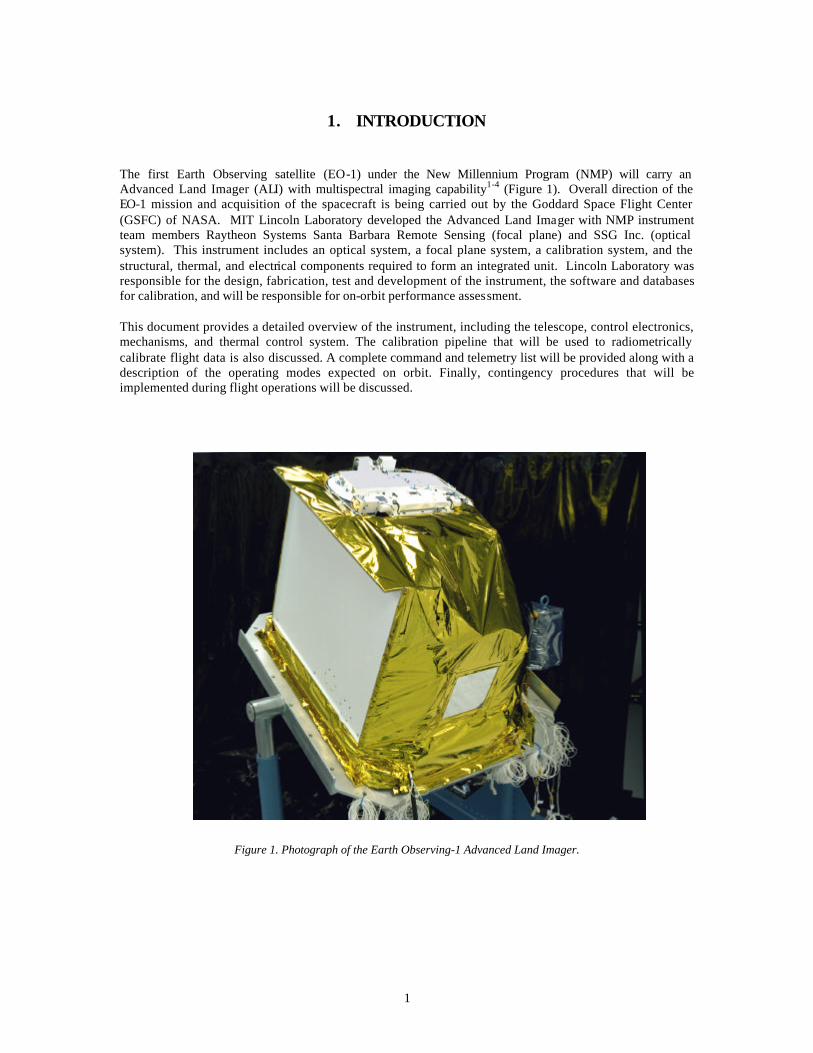
1. INTRODUCTION The first Earth Observing satellite (EO-1) under the New Millennium Program (NMP) will carry an Advanced Land Imager (ALI) with multispectral imaging capability1-4 (Figure 1). Overall direction of the EO-1 mission and acquisition of the spacecraft is being carried out by the Goddard Space Flight Center (GSFC) of NASA. MIT Lincoln Laboratory developed the Advanced Land Imager with NMP instrument team members Raytheon Systems Santa Barbara Remote Sensing (focal plane) and SSG Inc. (optical system). This instrument includes an optical system, a focal plane system, a calibration system, and the structural, thermal, and electrical components required to form an integrated unit. Lincoln Laboratory was responsible for the design, fabrication, test and development of the instrument, the software and databases for calibration, and will be responsible for on-orbit performance assessment. This document provides a detailed overview of the instrument, including the telescope, control electronics, mechanisms, and thermal control system. The calibration pipeline that will be used to radiometrically calibrate flight data is also discussed. A complete command and telemetry list will be provided along with a description of the operating modes expected on orbit. Finally, contingency procedures that will be implemented during flight operations will be discussed.
Figure 1. Photograph of the Earth Observing-1 Advanced Land Imager.

2
3
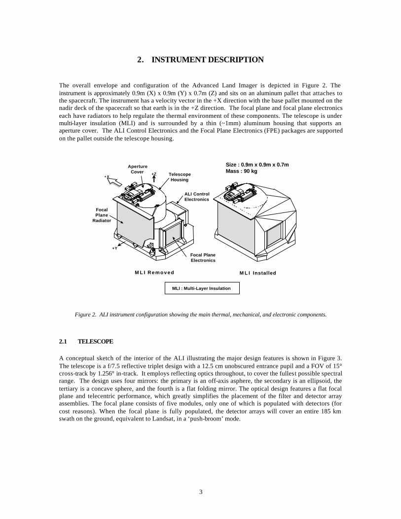
2. INSTRUMENT DESCRIPTION The overall envelope and configuration of the Advanced Land Imager is depicted in Figure 2. The instrument is approximately 0.9m (X) x 0.9m (Y) x 0.7m (Z) and sits on an aluminum pallet that attaches to the spacecraft. The instrument has a velocity vector in the +X direction with the base pallet mounted on the nadir deck of the spacecraft so that earth is in the +Z direction. The focal plane and focal plane electronics each have radiators to help regulate the thermal environment of these components. The telescope is under multi-layer insulation (MLI) and is surrounded by a thin (~1mm) aluminum housing that supports an aperture cover. The ALI Control Electronics and the Focal Plane Electronics (FPE) packages are supported on the pallet outside the telescope housing.
Figure 2. ALI instrument configuration showing the main thermal, mechanical, and electronic components.
2.1 TELESCOPE
A conceptual sketch of the interior of the ALI illustrating the major design features is shown in Figure 3. The telescope is a f/7.5 reflective triplet design with a 12.5 cm unobscured entrance pupil and a FOV of 15° cross-track by 1.256° in-track. It employs reflecting optics throughout, to cover the fullest possible spectral range. The design uses four mirrors: the primary is an off-axis asphere, the secondary is an ellipsoid, the tertiary is a concave sphere, and the fourth is a flat folding mirror. The optical design features a flat focal plane and telecentric performance, which greatly simplifies the placement of the filter and detector array assemblies. The focal plane consists of five modules, only one of which is populated with detectors (for cost reasons). When the focal plane is fully populated, the detector arrays will cover an entire 185 km swath on the ground, equivalent to Landsat, in a ‘push-broom’ mode.
MLI : Multi-Layer Insulation
+Z
+Y
M L I R e m o v e d M L I Installed
+ X TelescopeHousing
ALI ControlElectronics
Focal PlaneElectronics
ApertureCover
FocalPlane
Radiator
Size : 0.9m x 0.9m x 0.7mMass : 90 kg

4
Figure 3. A conceptual sketch of the ALI telescope and Focal Plane Assembly.
The telescope design incorporates silicon carbide mirrors and an Invar truss structure with appropriate mounting and attachment fittings. Silicon carbide has many favorable properties for space optical systems. It possesses a high stiffness to weight ratio and a low coefficient of thermal expansion. Although it has been used for space optical elements previously, it has not been used for such large mirrors. A photograph of the silicon carbide mirrors that are held in place by the Invar metering truss is shown in Figure 4.
Figure 4. Photograph of the silicon carbide mirrors supported by the Invar metering truss.
15
1.256°
Main Focal Plane Assembly
Multispectral /Panchromatic
Sensor AssemblyTen VNIR/SWIR bandson common readoutOperation at 220 K
SiC OpticsLow mass
Thermally stable
Wide FOV 1.256° x 15°All reflective telescope
Push broom data collectionNo scan mirror
Innovative in-flightcalibration
Solar calibrationLunar calibration
Internal lamps
Telescope features
• 12.5 cm entrance pupil
• 15° x 1.26° field-of-view
• Telecentric, f/7.5 design
• Unobscured, reflective optics
• Silicon carbide mirrors
• Wavefront error = 0.11 λ λ RMS @633 nm
5
2.2 FOCAL PLANE
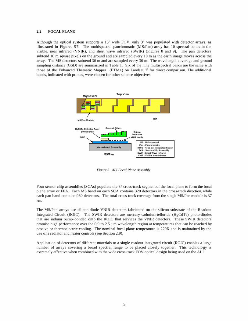
Although the optical system supports a 15° wide FOV, only 3° was populated with detector arrays, as illustrated in Figures 5-7. The multispectral panchromatic (MS/Pan) array has 10 spectral bands in the visible, near infrared (VNIR), and short wave infrared (SWIR) (Figures 8 and 9). The pan detectors subtend 10 m square pixels on the ground and are sampled every 10 m as the earth image moves across the array. The MS detectors subtend 30 m and are sampled every 30 m. The wavelength coverage and ground sampling distance (GSD) are summarized in Table 1. Six of the nine multispectral bands are the same with those of the Enhanced Thematic Mapper (ETM+) on Landsat 75 for direct comparison. The additional bands, indicated with primes, were chosen for other science objectives.
Top View
VNIRSWIR
MS/Pan SCAs
VNIR VNIR
VNIRSWIR
SWIRSWIR
MS/Pan Module
SiliconDetectors
VNIR bands
HgCdTe Detector ArraySWIR bands
Motherboard Assembly
Spectral Filters
MS/Pan
ROIC
MS : Multispectral Pan : PanchromaticROIC : Read-out Integrated Circuit SCA : Sensor Chip AssemblySWIR : Short Wave Infrared VNIR : Visible Near Infrared
•••SCA
Figure 5. ALI Focal Plane Assembly.
Four sensor chip assemblies (SCAs) populate the 3° cross-track segment of the focal plane to form the focal plane array or FPA. Each MS band on each SCA contains 320 detectors in the cross-track direction, while each pan band contains 960 detectors. The total cross-track coverage from the single MS/Pan module is 37 km. The MS/Pan arrays use silicon-diode VNIR detectors fabricated on the silicon substrate of the Readout Integrated Circuit (ROIC). The SWIR detectors are mercury-cadmium-telluride (HgCdTe) photo-diodes that are indium bump -bonded onto the ROIC that services the VNIR detectors. These SWIR detectors promise high performance over the 0.9 to 2.5 µm wavelength region at temperatures that can be reached by passive or thermoelectric cooling. The nominal focal plane temperature is 220K and is maintained by the use of a radiator and heater controls (see Section 2.9). Application of detectors of different materials to a single readout integrated circuit (ROIC) enables a large number of arrays covering a broad spectral range to be placed closely together. This technology is extremely effective when combined with the wide cross-track FOV optical design being used on the ALI.
6
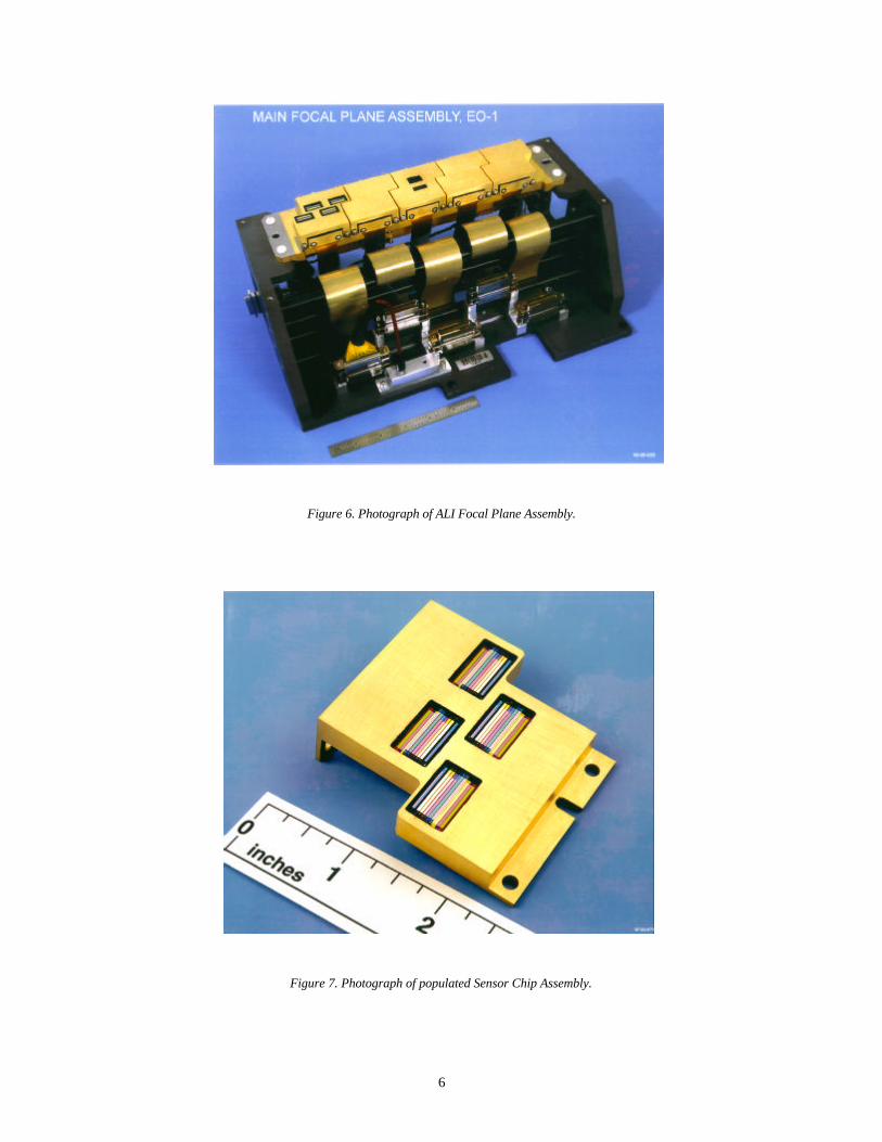
Figure 6. Photograph of ALI Focal Plane Assembly.
Figure 7. Photograph of populated Sensor Chip Assembly.
7
TABLE 1
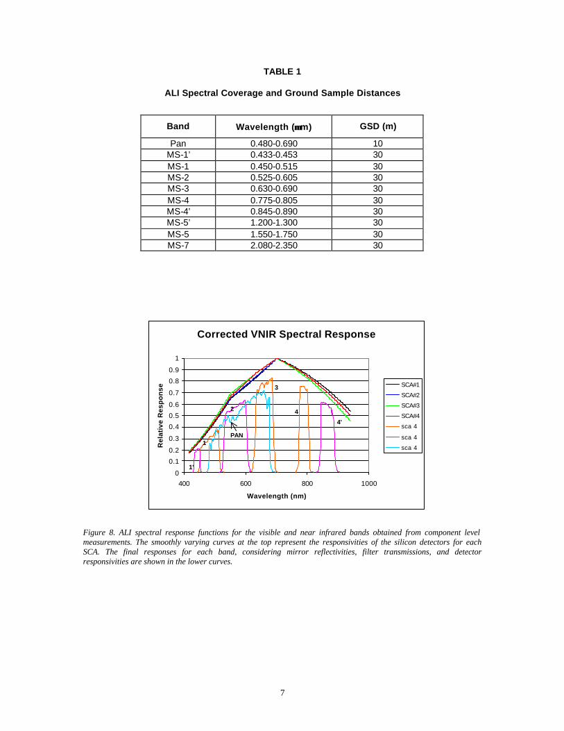
ALI Spectral Coverage and Ground Sample Distances
Band Wavelength (µµm) GSD (m)
Pan 0.480-0.690 10 MS-1’ 0.433-0.453 30 MS-1 0.450-0.515 30 MS-2 0.525-0.605 30 MS-3 0.630-0.690 30 MS-4 0.775-0.805 30 MS-4’ 0.845-0.890 30 MS-5’ 1.200-1.300 30 MS-5 1.550-1.750 30 MS-7 2.080-2.350 30
Figure 8. ALI spectral response functions for the visible and near infrared bands obtained from component level measurements. The smoothly varying curves at the top represent the responsivities of the silicon detectors for each SCA. The final responses for each band, considering mirror reflectivities, filter transmissions, and detector responsivities are shown in the lower curves.
Corrected VNIR Spectral Response
0
0.1
0.2
0.3
0.4
0.5
0.6
0.7
0.8
0.9
1
400 600 800 1000
Wavelength (nm)
Rel
ativ
e R
esp
on
se
SCA#1
SCA#2
SCA#3
SCA#4
sca 4
sca 4
sca 4
1'
1
2
3
4
4'
PAN
8
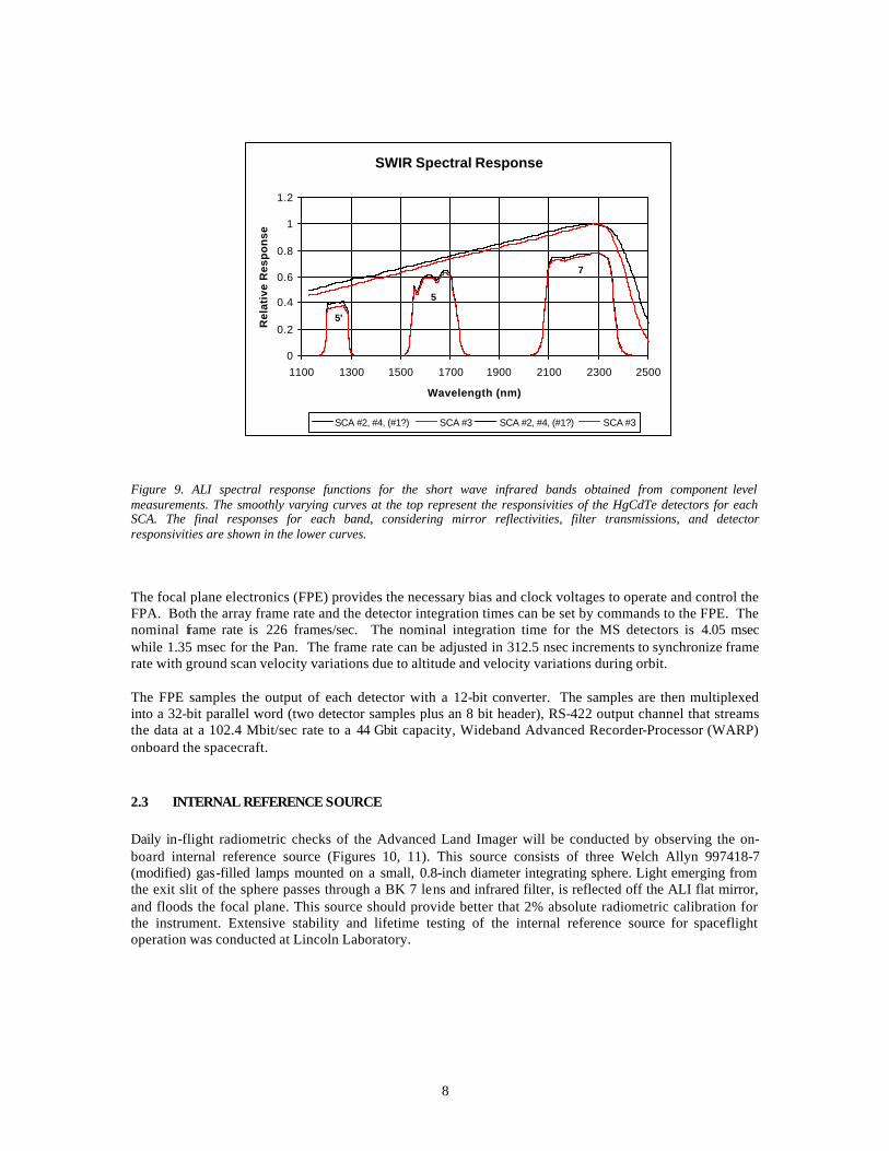
Figure 9. ALI spectral response functions for the short wave infrared bands obtained from component level measurements. The smoothly varying curves at the top represent the responsivities of the HgCdTe detectors for each SCA. The final responses for each band, considering mirror reflectivities, filter transmissions, and detector responsivities are shown in the lower curves.
The focal plane electronics (FPE) provides the necessary bias and clock voltages to operate and control the FPA. Both the array frame rate and the detector integration times can be set by commands to the FPE. The nominal frame rate is 226 frames/sec. The nominal integration time for the MS detectors is 4.05 msec while 1.35 msec for the Pan. The frame rate can be adjusted in 312.5 nsec increments to synchronize frame rate with ground scan velocity variations due to altitude and velocity variations during orbit. The FPE samples the output of each detector with a 12-bit converter. The samples are then multiplexed into a 32-bit parallel word (two detector samples plus an 8 bit header), RS-422 output channel that streams the data at a 102.4 Mbit/sec rate to a 44 Gbit capacity, Wideband Advanced Recorder-Processor (WARP) onboard the spacecraft.
2.3 INTERNAL REFERENCE SOURCE
Daily in-flight radiometric checks of the Advanced Land Imager will be conducted by observing the on-board internal reference source (Figures 10, 11). This source consists of three Welch Allyn 997418-7 (modified) gas-filled lamps mounted on a small, 0.8-inch diameter integrating sphere. Light emerging from the exit slit of the sphere passes through a BK 7 lens and infrared filter, is reflected off the ALI flat mirror, and floods the focal plane. This source should provide better that 2% absolute radiometric calibration for the instrument. Extensive stability and lifetime testing of the internal reference source for spaceflight operation was conducted at Lincoln Laboratory.
SWIR Spectral Response
0
0.2
0.4
0.6
0.8
1
1.2
1100 1300 1500 1700 1900 2100 2300 2500
Wavelength (nm)
Rel
ativ
e R
esp
on
se
SCA #2, #4, (#1?) SCA #3 SCA #2, #4, (#1?) SCA #3
5
5'
7

9
Figure 10. EO-1 ALI internal reference source.
Figure 11. Photograph of internal reference source.
Following each observation, after the aperture cover has been closed, the three internal calibration lamps are powered by the ALI Control Electronics. After an eight-second stabilization period the lamps are sequentially powered down in a staircase fashion, with two-second exposures between each step. In this manner, the focal plane will receive a three point radiometric calibration after each observation.
Integrat ing Sphere
Welch Allyn Lamp
LensInfrared Filter
Internal Reference Source

10
2.4 MECHANISMS
Figure 12 illustrates three motor-driven mechanisms employed by the ALI. The aperture cover opens for a data collection event and closes after data collection. The cover is driven by a two-phase stepper motor and four LEDs are mounted near the cover for discrete status monitoring (open, closed, launch latch released, fail safe released). There is also an aperture cover throwback spring that is enabled by firing a High Output Paraffin Actuator (HOPA). The throwback spring would be used in case of motor failure; however, shutting the aperture cover would not be possible after invoking this option.
Figure 12. Mechanisms used in ALI.
Figure 13. Photograph of the ALI Aperture Cover Assembly.
ApertureSelector Diffuser Solar BeamCover
Scattered Light
SecondaryMirror
Solar CalibrationCover - Closed
Diffuser - DeployedAperture Selector - Scanned
Aperture Cover
Aperture Selector
11
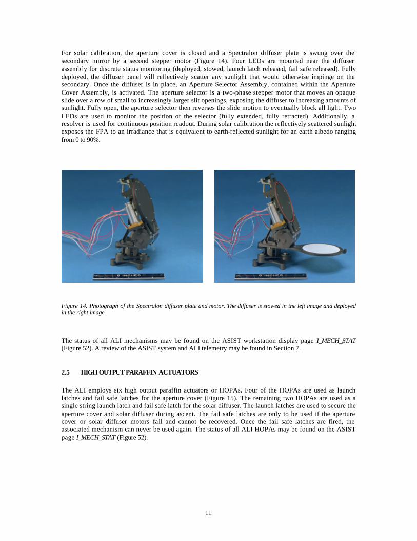
For solar calibration, the aperture cover is closed and a Spectralon diffuser plate is swung over the secondary mirror by a second stepper motor (Figure 14). Four LEDs are mounted near the diffuser assemb ly for discrete status monitoring (deployed, stowed, launch latch released, fail safe released). Fully deployed, the diffuser panel will reflectively scatter any sunlight that would otherwise impinge on the secondary. Once the diffuser is in place, an Aperture Selector Assembly, contained within the Aperture Cover Assembly, is activated. The aperture selector is a two-phase stepper motor that moves an opaque slide over a row of small to increasingly larger slit openings, exposing the diffuser to increasing amounts of sunlight. Fully open, the aperture selector then reverses the slide motion to eventually block all light. Two LEDs are used to monitor the position of the selector (fully extended, fully retracted). Additionally, a resolver is used for continuous position readout. During solar calibration the reflectively scattered sunlight exposes the FPA to an irradiance that is equivalent to earth-reflected sunlight for an earth albedo ranging from 0 to 90%.
Figure 14. Photograph of the Spectralon diffuser plate and motor. The diffuser is stowed in the left image and deployed in the right image.
The status of all ALI mechanisms may be found on the ASIST workstation display page I_MECH_STAT (Figure 52). A review of the ASIST system and ALI telemetry may be found in Section 7.
2.5 HIGH OUTPUT PARAFFIN ACTUATORS
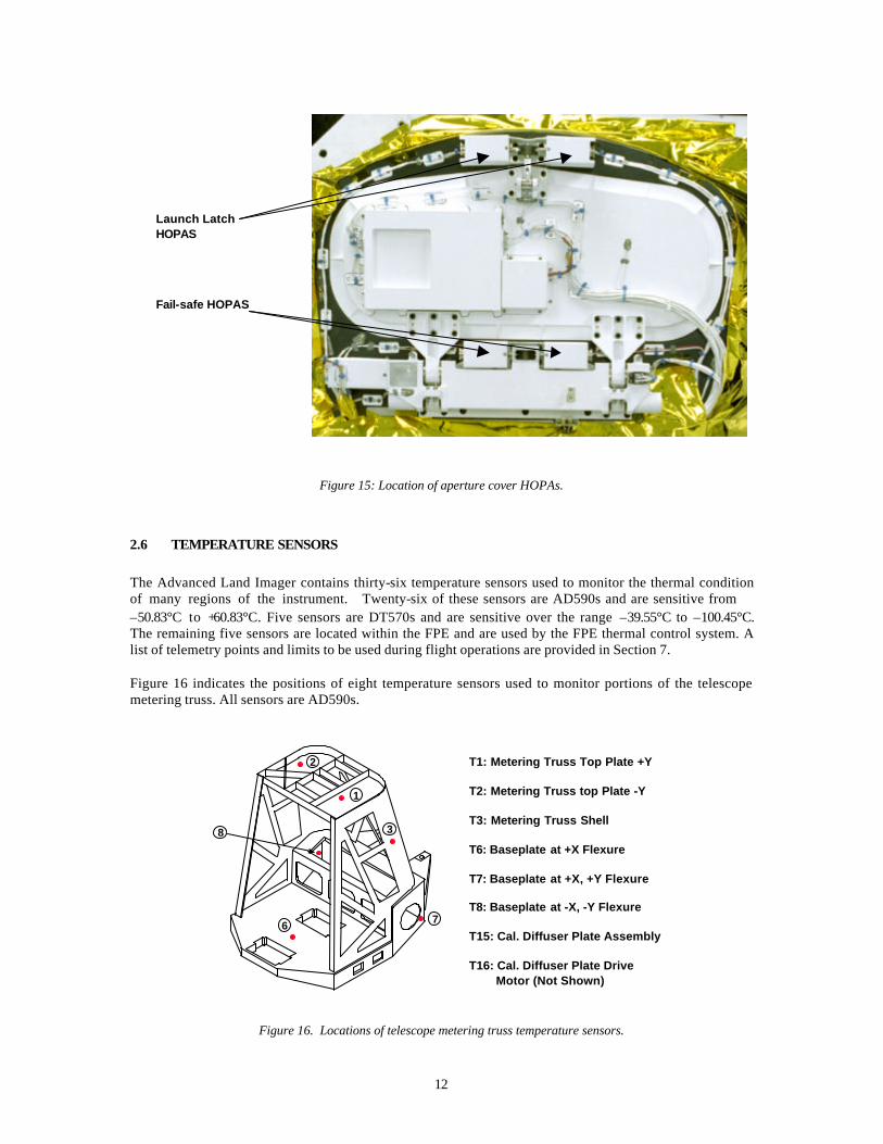
The ALI employs six high output paraffin actuators or HOPAs. Four of the HOPAs are used as launch latches and fail safe latches for the aperture cover (Figure 15). The remaining two HOPAs are used as a single string launch latch and fail safe latch for the solar diffuser. The launch latches are used to secure the aperture cover and solar diffuser during ascent. The fail safe latches are only to be used if the aperture cover or solar diffuser motors fail and cannot be recovered. Once the fail safe latches are fired, the associated mechanism can never be used again. The status of all ALI HOPAs may be found on the ASIST page I_MECH_STAT (Figure 52).
12
Figure 15: Location of aperture cover HOPAs.
2.6 TEMPERATURE SENSORS
The Advanced Land Imager contains thirty-six temperature sensors used to monitor the thermal condition of many regions of the instrument. Twenty-six of these sensors are AD590s and are sensitive from –50.83°C to +60.83°C. Five sensors are DT570s and are sensitive over the range –39.55°C to –100.45°C. The remaining five sensors are located within the FPE and are used by the FPE thermal control system. A list of telemetry points and limits to be used during flight operations are provided in Section 7. Figure 16 indicates the positions of eight temperature sensors used to monitor portions of the telescope metering truss. All sensors are AD590s.
Figure 16. Locations of telescope metering truss temperature sensors.
1
2
3
6 7
8
T1: Metering Truss Top Plate +Y
T2: Metering Truss top Plate -Y
T3: Metering Truss Shell
T6: Baseplate at +X Flexure
T7: Baseplate at +X, +Y Flexure
T8: Baseplate at -X, -Y Flexure
T15: Cal. Diffuser Plate Assembly
T16: Cal. Diffuser Plate Drive Motor (Not Shown)
Launch Latch HOPAS
Fail-safe HOPAS
13
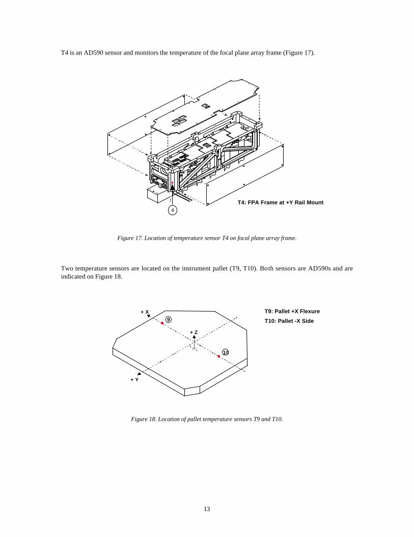
T4 is an AD590 sensor and monitors the temperature of the focal plane array frame (Figure 17).
Figure 17. Location of temperature sensor T4 on focal plane array frame.
Two temperature sensors are located on the instrument pallet (T9, T10). Both sensors are AD590s and are indicated on Figure 18.
Figure 18. Location of pallet temperature sensors T9 and T10.
4 T4: FPA Frame at +Y Rail Mount
+ X
+ Y
+ Z
9
10
T9: Pallet +X Flexure
T10: Pallet -X Side
4

14
Figure 19 indicates the positions of seven temperature sensors used to monitor portions of the focal plane array and radiator. T20 and T32 are Ad590 and T19, T21, T29, T33, and T34 are DT570 sensors.
Figure 19. Location of focal plane array and radiator temperature sensors.
The locations of five temperature sensors located on the telescope aperture cover are indicated in Figure 20. All sensors are AD590s.
Figure 20. Locations of telescope aperture cover temperature sensors.
MAIN FPA
19
2021
29
32
33
34
T19: FPA Conductor Bar, internal railinterface
T20: FPA Conductor Bar, internal flex link
T21: FPA Conductor Bar, internal flex link
T29: FPA Conductor Bar at radiator
T33: FPA Radiator, top
T32: FPA Radiator, bottom
T34: FPA Radiator, bottom
(oppositecorner)
24
T24: TAC Drive Motor Structure
T25: TAC Drive Motor
T26: TAC Launch Latch
T27: TAC
T28: Aperture Selector Motor
25
26
27
28
15
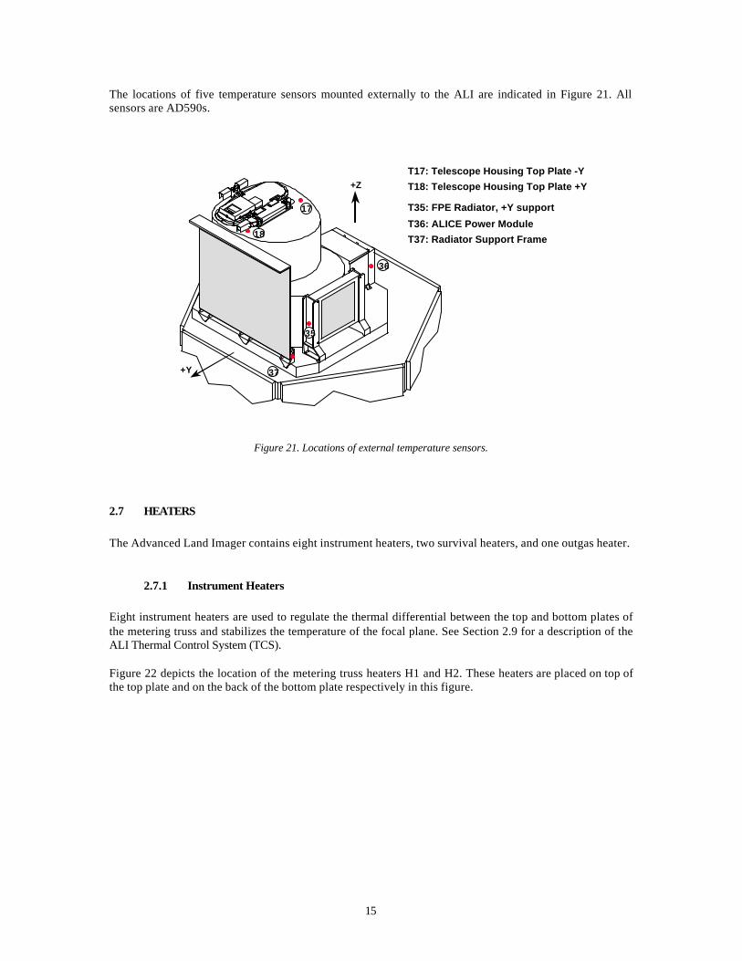
The locations of five temperature sensors mounted externally to the ALI are indicated in Figure 21. All sensors are AD590s.
Figure 21. Locations of external temperature sensors.
2.7 HEATERS
The Advanced Land Imager contains eight instrument heaters, two survival heaters, and one outgas heater.
2.7.1 Instrument Heaters
Eight instrument heaters are used to regulate the thermal differential between the top and bottom plates of the metering truss and stabilizes the temperature of the focal plane. See Section 2.9 for a description of the ALI Thermal Control System (TCS). Figure 22 depicts the location of the metering truss heaters H1 and H2. These heaters are placed on top of the top plate and on the back of the bottom plate respectively in this figure.
36
+Z
+Y
35
37
T17: Telescope Housing Top Plate -Y
T36: ALICE Power Module
T37: Radiator Support Frame
T18: Telescope Housing Top Plate +Y
T35: FPE Radiator, +Y support17
18

16
Figure 22. Locations of metering truss heaters H1 and H2.
Heaters H7 – H11 are used to regulate the temperature of the focal plane radiator. These heaters are spread along the radiator and are located in Figure 23.
Figure 23. Locations of focal plane radiator heaters H7-H11.
The location of heater H12 is depicted in Figure 24. This heater is located on the focal plane conductor bar and is used to help regulate the focal plane temperature.
H1
H2 (Mounted belowbottom plate)
MAIN FPAFPA Radiator
H7-11 Mounted to back of radiator
17
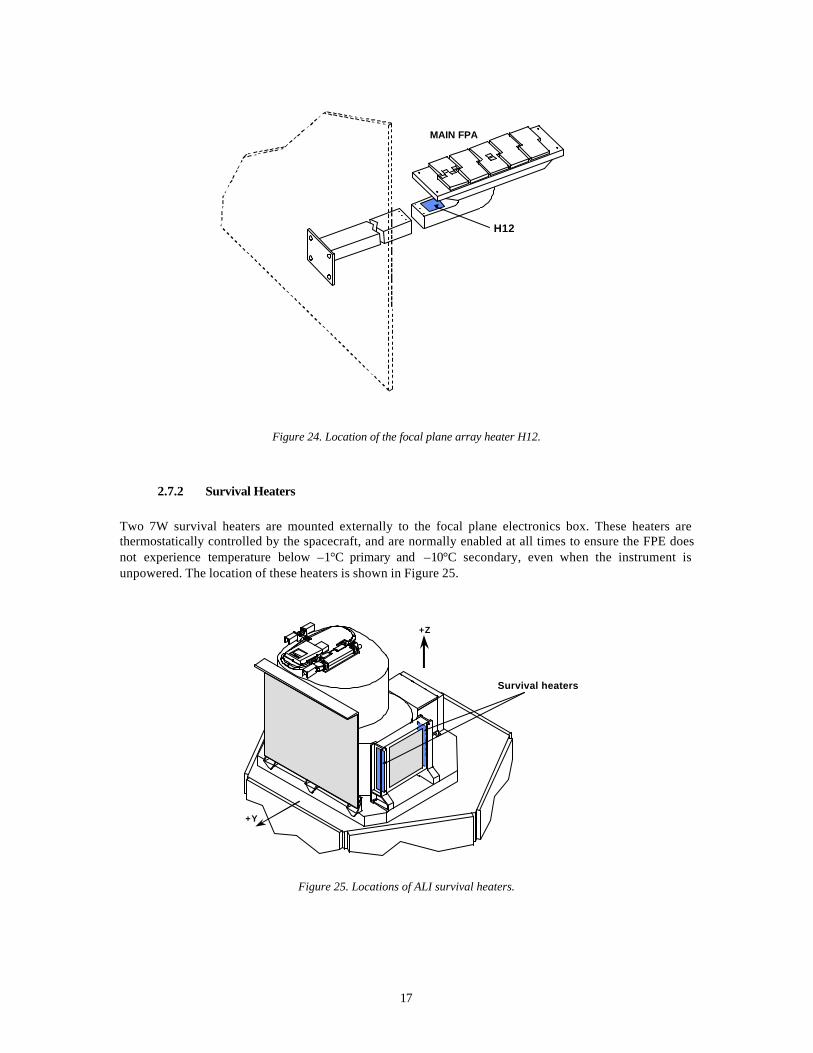
Figure 24. Location of the focal plane array heater H12.
2.7.2 Survival Heaters
Two 7W survival heaters are mounted externally to the focal plane electronics box. These heaters are thermostatically controlled by the spacecraft, and are normally enabled at all times to ensure the FPE does not experience temperature below –1°C primary and –10°C secondary, even when the instrument is unpowered. The location of these heaters is shown in Figure 25.
Figure 25. Locations of ALI survival heaters.
MAIN FPA
H12
+Z
+Y
Survival heaters
18
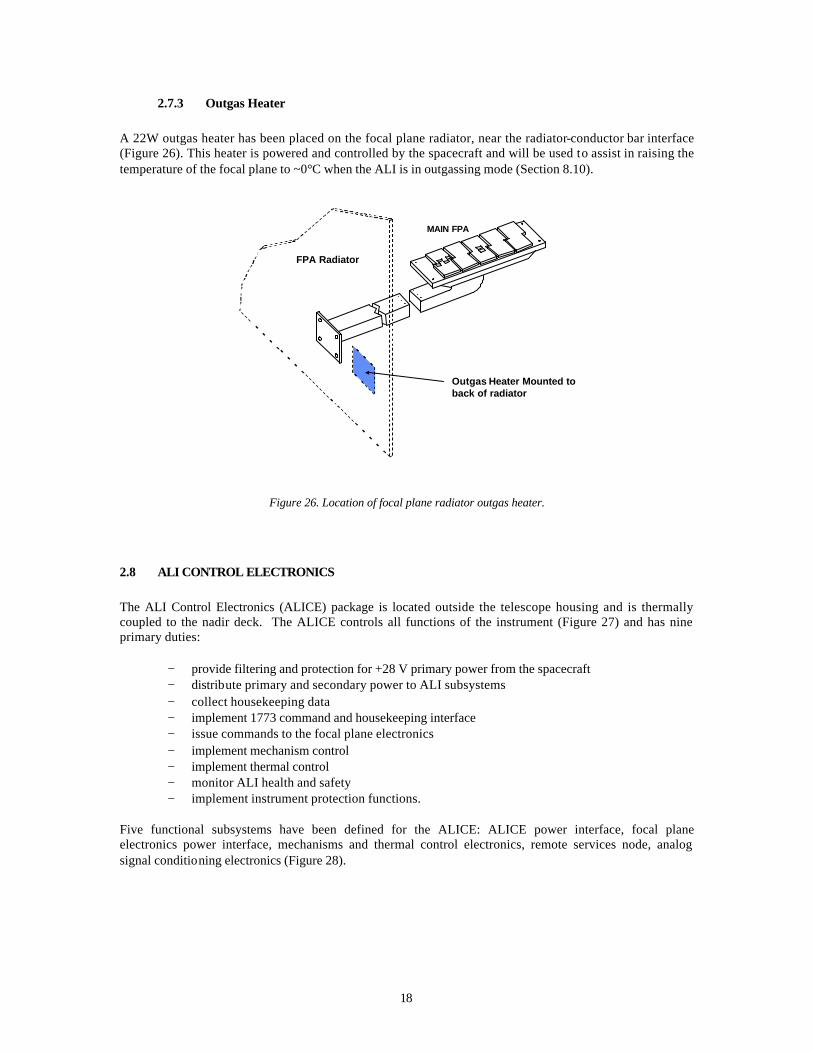
2.7.3 Outgas Heater
A 22W outgas heater has been placed on the focal plane radiator, near the radiator-conductor bar interface (Figure 26). This heater is powered and controlled by the spacecraft and will be used to assist in raising the temperature of the focal plane to ~0°C when the ALI is in outgassing mode (Section 8.10).
Figure 26. Location of focal plane radiator outgas heater.
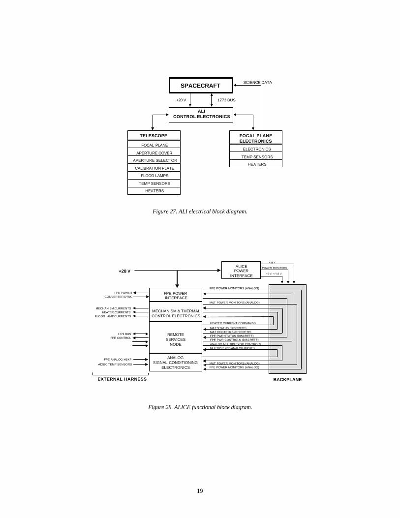
2.8 ALI CONTROL ELECTRONICS
The ALI Control Electronics (ALICE) package is located outside the telescope housing and is thermally coupled to the nadir deck. The ALICE controls all functions of the instrument (Figure 27) and has nine primary duties:
− provide filtering and protection for +28 V primary power from the spacecraft − distribute primary and secondary power to ALI subsystems − collect housekeeping data − implement 1773 command and housekeeping interface − issue commands to the focal plane electronics − implement mechanism control − implement thermal control − monitor ALI health and safety − implement instrument protection functions.
Five functional subsystems have been defined for the ALICE: ALICE power interface, focal plane electronics power interface, mechanisms and thermal control electronics, remote services node, analog signal conditioning electronics (Figure 28).
MAIN FPA
Outgas Heater Mounted to back of radiator
FPA Radiator
19
Figure 27. ALI electrical block diagram.
Figure 28. ALICE functional block diagram.
SPACECRAFT
ALICONTROL ELECTRONICS
FOCAL PLANEELECTRONICS
SCIENCE DATA
TELESCOPE
+28 V 1773 BUS
FOCAL PLANE
APERTURE COVER
APERTURE SELECTOR
CALIBRATION PLATE
FLOOD LAMPS
TEMP SENSORS
HEATERS
ELECTRONICS
TEMP SENSORS
HEATERS
REMOTESERVICES
NODE
+28 V
1773 BUS
ALICEPOWER
INTERFACE
ANALOGSIGNAL CONDITIONING
ELECTRONICS
FPE CONTROL
MECHANISM & THERMALCONTROL ELECTRONICS
FPE ANALOG HSKP
AD590 TEMP SENSORS
FPE POWERINTERFACE
BACKPLANE
FPE POWER
MECHANISM CURRENTS
FLOOD LAMP CURRENTSHEATER CURRENTS
FPE POWER MONITORS (ANALOG)
M&T POWER MONITORS (ANALOG)
M&T POWER MONITORS (ANALOG)FPE POWER MONITORS (ANALOG)
MULTIPLEXED ANALOG INPUTSANALOG MULTIPLEXOR CONTROLS
M&T STATUS (DISCRETE)M&T CONTROLS (DISCRETE)
FPE PWR CONTROLS (DISCRETE)FPE PWR STATUS (DISCRETE)
CONVERTER SYNC
POWER MONITORS
+5 V, +/-15 V
+28 V
EXTERNAL HARNESS
HEATER CURRENT COMMANDS

20
2.8.1 ALICE Power Interface
The ALICE Power Interface or API filters spacecraft +28 V primary power and distributes primary (+28 V) and secondary (+5V, +/-15 V) power to the ALICE backplane (Figure 29). Additionally, primary power voltage and current monitor signals are routed to the ALICE Analog Signal Conditioning Electronics (ASCE) by the API.
Figure 29. ALICE power interface (API).
2.8.2 Focal Plane Electronics Power Interface
The FPE Power Interface or FPEPI also filters spacecraft primary power and distributes secondary (+5 V, +/-15 V) to the focal plane electronics (Figure 30). +28 V current trip circuits are in place to protect the FPEPI if excess +28 V current is on the primary power bus. FPE power monitor signals are also routed to the ASCE.
Figure 30. FPE power interface (FPEPI).
+28 V
INTERPOINTMFL2805S
DC-DC CONVERTER
OUTPUTFILTER
INTERPOINTFMD-461 FILTER
INTERPOINTMFL2815D
DC-DC CONVERTER
POWER MONITORSIGNAL
CONDITIONING
AL
ICE
BA
CK
PL
AN
E
+28 V
+5 V
+/-15 V
+28 V VOLTAGE MONITOR
+28 V CURRENT MONITOR
OUTPUTFILTER
INTERPOINTFMD-461 FILTER
AL
ICE
BA
CK
PL
AN
E
+28 V
INTERPOINTMFL2805S
DC-DC CONVERTER
OUTPUTFILTER
+5 V +28V CURRENTTRIP CIRCUIT
INTERPOINTMFL2805S
DC-DC CONVERTER
OUTPUTFILTER
+5 V +28V CURRENTTRIP CIRCUIT
INTERPOINTMFL2815D
DC-DC CONVERTER
OUTPUTFILTER
+28V CURRENTTRIP CIRCUIT
INTERPOINTMFL2815D
DC-DC CONVERTER
OUTPUTFILTER
+/-15 V +28V CURRENTTRIP CIRCUIT
FO
CA
L P
LA
NE
EL
EC
TR
ON
ICS
+/-15 V
+28 V CURRENT MONITOR+28 V POWER ENABLE+28 V TRIP RESET+28 V TRIP STATUS
CONVERTER SYNC
21
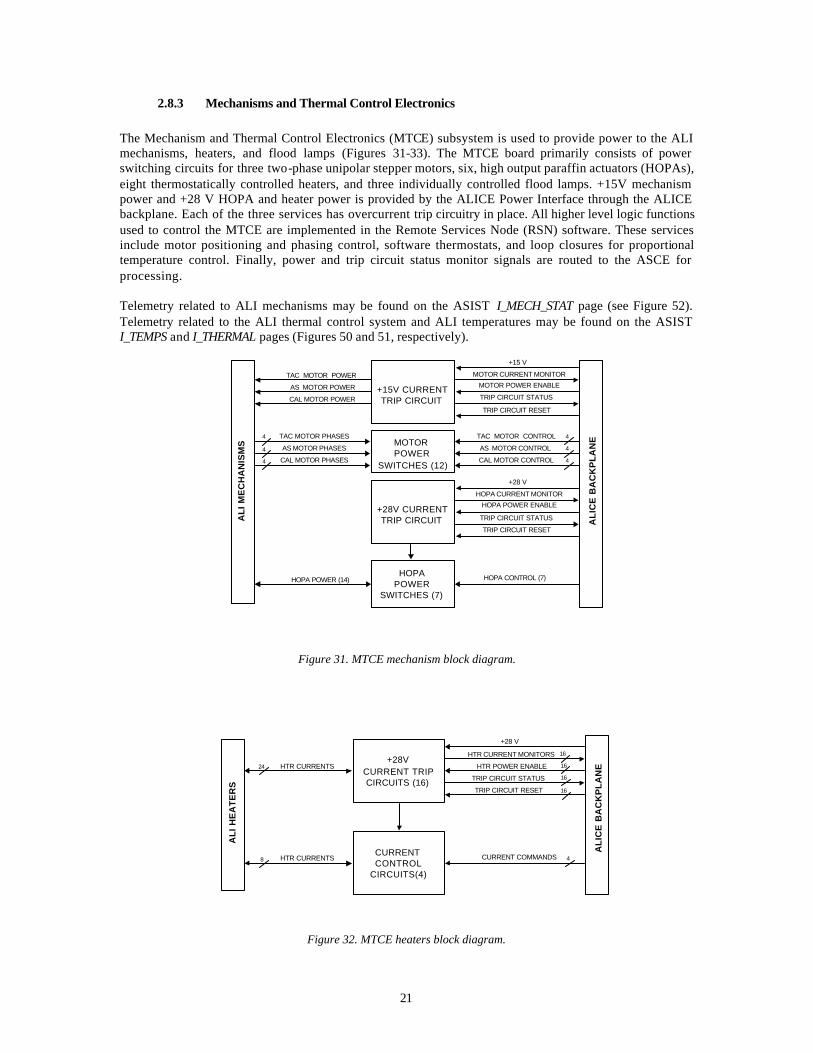
2.8.3 Mechanisms and Thermal Control Electronics
The Mechanism and Thermal Control Electronics (MTCE) subsystem is used to provide power to the ALI mechanisms, heaters, and flood lamps (Figures 31-33). The MTCE board primarily consists of power switching circuits for three two-phase unipolar stepper motors, six, high output paraffin actuators (HOPAs), eight thermostatically controlled heaters, and three individually controlled flood lamps. +15V mechanism power and +28 V HOPA and heater power is provided by the ALICE Power Interface through the ALICE backplane. Each of the three services has overcurrent trip circuitry in place. All higher level logic functions used to control the MTCE are implemented in the Remote Services Node (RSN) software. These services include motor positioning and phasing control, software thermostats, and loop closures for proportional temperature control. Finally, power and trip circuit status monitor signals are routed to the ASCE for processing. Telemetry related to ALI mechanisms may be found on the ASIST I_MECH_STAT page (see Figure 52). Telemetry related to the ALI thermal control system and ALI temperatures may be found on the ASIST I_TEMPS and I_THERMAL pages (Figures 50 and 51, respectively).
Figure 31. MTCE mechanism block diagram.
Figure 32. MTCE heaters block diagram.
AL
ICE
BA
CK
PL
AN
E
+15V CURRENTTRIP CIRCUIT
MOTOR CURRENT MONITOR
MOTOR POWER ENABLE
TRIP CIRCUIT STATUS
TRIP CIRCUIT RESET
+15 V
TAC MOTOR POWER
AS MOTOR POWER
CAL MOTOR POWER
MOTORPOWER
SWITCHES (12)
TAC MOTOR CONTROL
AS MOTOR CONTROL
CAL MOTOR CONTROL
TAC MOTOR PHASES
AS MOTOR PHASES
CAL MOTOR PHASES
+28V CURRENTTRIP CIRCUIT
HOPA CURRENT MONITOR
HOPA POWER ENABLE
TRIP CIRCUIT STATUS
TRIP CIRCUIT RESET
+28 V
HOPAPOWER
SWITCHES (7)
HOPA CONTROL (7)HOPA POWER (14)
AL
I M
EC
HA
NIS
MS
4
4
4
4
4
4
AL
ICE
BA
CK
PL
AN
E
+28VCURRENT TRIPCIRCUITS (16)
HTR CURRENT MONITORS
HTR POWER ENABLE
TRIP CIRCUIT STATUS
TRIP CIRCUIT RESET
+28 V
AL
I H
EA
TE
RS
HTR CURRENTS
CURRENTCONTROL
CIRCUITS(4)
HTR CURRENTS CURRENT COMMANDS
24
8 4
16
16
16
16
22
Figure 33. MTCE flood lamps block diagram.
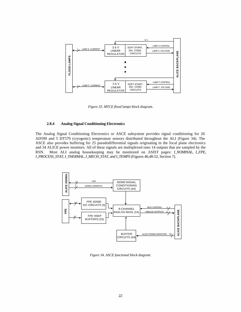
2.8.4 Analog Signal Conditioning Electronics
The Analog Signal Conditioning Electronics or ASCE subsystem provides signal conditioning for 26 AD590 and 5 DT570 (cryogenic) temperature sensors distributed throughout the ALI (Figure 34). The ASCE also provides buffering for 25 pseudodifferential signals originating in the focal plane electronics and 34 ALICE power monitors. All of these signals are multiplexed onto 14 outputs that are sampled by the RSN. Most ALI analog housekeeping may be monitored on ASIST pages: I_NOMINAL, I_FPE, I_PROCESS_STAT, I_THERMAL, I_MECH_STAT, and I_TEMPS (Figures 46,48-52, Section 7).
Figure 34. ASCE functional block diagram.
AL
ICE
BA
CK
PL
AN
E8-CHANNELANALOG MUXs (14) ANALOG OUTPUTS
MUX CONTROL
AL
ICE
AD
590s
BUFFERCIRCUITS (34)
ALICE POWER MONITORS
AD590 SIGNALCONDITIONINGCIRCUITS (44)
FP
E
AD590 CURRENTS
+15V
FPE HSKPBUFFERS (25)
FPE AD590S/C CIRCUITS (3)
4
28
14
3
3
3
4
AL
ICE
BA
CK
PL
AN
E
5 V
FL
OO
D L
AM
PS
LAMP A CURRENT3.6 V
LINEARREGULATOR
LAMP A CONTROL
2LAMP A VOLTAGE
SOFT START,SIG. COND.CIRCUITS
LAMP F CURRENT3.6 V
LINEARREGULATOR
LAMP F CONTROL
2LAMP F VOLTAGE
SOFT START,SIG. COND.CIRCUITS
23
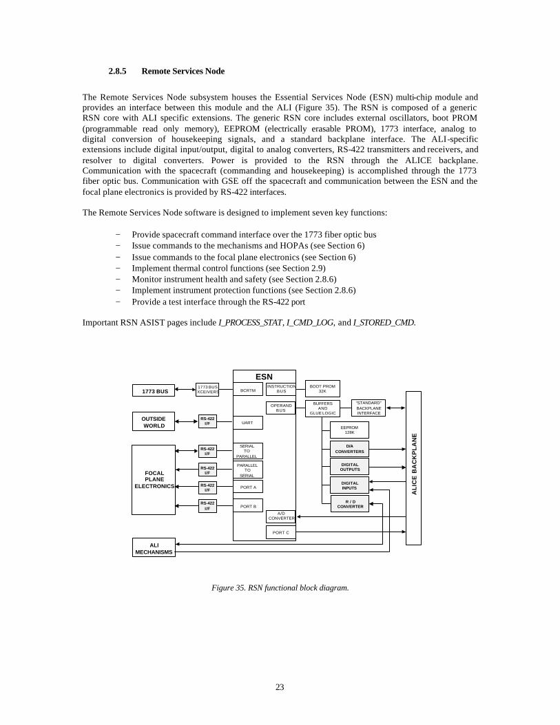
2.8.5 Remote Services Node
The Remote Services Node subsystem houses the Essential Services Node (ESN) multi-chip module and provides an interface between this module and the ALI (Figure 35). The RSN is composed of a generic RSN core with ALI specific extensions. The generic RSN core includes external oscillators, boot PROM (programmable read only memory), EEPROM (electrically erasable PROM), 1773 interface, analog to digital conversion of housekeeping signals, and a standard backplane interface. The ALI-specific extensions include digital input/output, digital to analog converters, RS-422 transmitters and receivers, and resolver to digital converters. Power is provided to the RSN through the ALICE backplane. Communication with the spacecraft (commanding and housekeeping) is accomplished through the 1773 fiber optic bus. Communication with GSE off the spacecraft and communication between the ESN and the focal plane electronics is provided by RS-422 interfaces. The Remote Services Node software is designed to implement seven key functions:
− Provide spacecraft command interface over the 1773 fiber optic bus − Issue commands to the mechanisms and HOPAs (see Section 6) − Issue commands to the focal plane electronics (see Section 6) − Implement thermal control functions (see Section 2.9) − Monitor instrument health and safety (see Section 2.8.6) − Implement instrument protection functions (see Section 2.8.6) − Provide a test interface through the RS-422 port
Important RSN ASIST pages include I_PROCESS_STAT, I_CMD_LOG, and I_STORED_CMD.
Figure 35. RSN functional block diagram.
ESNBCRTM
UART
SERIALTO
PARALLEL
PARALLELTO
SERIAL
PORT A
PORT B
1773 BUSXCEIVERS
RS-422I/F
RS-422I/F
RS-422I/F
RS-422I/F
RS-422I/F
BOOT PROM32K
BUFFERSAND
GLUE LOGIC
EEPROM128K
D/ACONVERTERS
DIGITALOUTPUTS
DIGITALINPUTS
INSTRUCTIONBUS
OPERANDBUS
AL
ICE
BA
CK
PL
AN
E
“STANDARD”BACKPLANEINTERFACE
1773 BUS
OUTSIDEWORLD
FOCALPLANE
ELECTRONICS
ALIMECHANISMS
R / DCONVERTER
A/DCONVERTER
PORT C

24
2.8.6 Instrument Health and Safety Monitoring
In addition to providing power and controlling all functions of the instrument, ALICE also continuously monitors key parameters to verify the health of the instrument. These include circuit breakers and health and safety interlocks. Eight software controlled ‘circuit breakers’ have been implemented in ALICE to protect hardware against short circuits in the following areas:
− HOPA power − Heater bank 1 − Heater bank 2 − Heater bank 3 − Heater bank 4 − Motor power − FPE thermal control power − FPE operational power
If any circuit breaker is tripped, it is automatically reset. If a second trip occurs within 10 seconds the associated subsystem is disabled. Once a subsystem is disabled, the circuit breaker may only be reset via ground commands. Eighteen health and safety software ‘interlocks’ (Figure 47, Section 7) are also implemented in ALICE to assist with instrument failure, detection, and correction. These interlocks include the following:
− If FPE radiator temperature > 58.6 C then disable FPE operational and thermal power - Cleared when FPE operational or thermal power is reenabled
− If FPE +28 V input current > 1.5 amps then disable FPE operational and thermal power - Cleared when FPE operational or thermal power is reenabled
− If FPE operational time > 30000 seconds then disable FPE operational power - Cleared when FPE operational power is reenabled
− If HOPA > 1.1 amps then disarm and disable HOPAs - Cleared when any HOPA is fired
− If HOPA on time > 180 seconds then disarm and disable HOPA - Cleared when any HOPA is fired
− If aperture cover motor temperature > 58.6 C then disable motor power and turn off all motor phases. - Cleared when any motor is reactivated
− If solar diffuser motor temperature > 58.6 C then disable motor power and turn off all motor phases. - Cleared when any motor is reactivated
− If aperture selector motor temperature > 58.6 C then disable motor power and turn off all motor phases. - Cleared when any motor is reactivated
− If motor current > 2.1 amps then disable motor power and turn off all motor phases. - Cleared when any motor is reactivated
− If motor turn on time > 60 seconds then disable motor power and turn off all motor phases. - Cleared when any motor is reactivated
− If lamp 1 current > 0.98 amps disable lamp power and turn off all lamps - Cleared when any lamp is turned on
− If lamp 2 current > 0.98 amps disable lamp power and turn off all lamps - Cleared when any lamp is turned on
− If lamp 3 current > 0.98 amps disable lamp power and turn off all lamps - Cleared when any lamp is turned on
25
− If lamp on time > 60 seconds disable lamp power and turn off all lamps - Cleared when any lamp is turned on
− If heater bank 1 current > 1.1 amps then disable heater bank 1 power - Cleared when heater bank 1 is reenabled
− If heater bank 3 current > 1.1 amps then disable heater bank 3 power - Cleared when heater bank 3 is reenabled
− If heater bank 4 current > 1.1 amps then disable heater bank 4 power - Cleared when heater bank 4 is reenabled
− If FPE operational power on and FPA rail heater power > 0 Watts then disable FPE thermal control power - Cleared when the FPE thermal power is reenabled
All interlock parameter values may be changed using the /I_SET_DEFAULT command. However, the default parameters should be used until a need for a change is identified.
2.9 THERMAL CONTROL SYSTEM
The ALI Thermal Control System (TCS) regulates the thermal differential between the top and bottom plates of the metering truss and stabilizes the temperature of the focal plane at one of five set points. The nominal FPA temperature set-point is 220 K. Possible alternatives are 225 K, 215 K, 210 K, and 205 K (See section 6.1.20). Status of the ALI thermal control system and a summary of ALI temperatures may be found on the ASIST I_THERMAL and I_TEMPS pages (Figures 51 and 50, respectively). The ALI TCS is invoked once a second and has three main functions:
− Control heaters H1 and H2 (located on the top and bottom plates of metering truss, respectively)
− Control heaters H12 (located on the internal side of the FPA conductor bar) − Control heaters H7–H11 (located on the FPA radiator)
For each control function, several modes have been implemented and are detailed below. Modes, which are active upon ALICE startup (default modes), are identified in the descriptions. “Non-flight” modes can be considered backup modes and have been useful during various stages of TCS development. Non-flight modes can be invoked via ground command All automatic controls are disabled when the system is placed in “Manual” mode. In this mode, each heater can be individually controlled via ground command. However, it is recommended that the default mode be used whenever the ALI is under nominal operating conditions.
2.9.1 Heater H1, H2 Control
The ALI thermal control system regulates the thermal differential between the telescope metering truss top and bottom plates by regulating power to heaters H1 and H2 (See Section 2.7.1). H1 is a 5W heater located on the top plate of the metering truss. H2 is a 5W heater located on the bottom plate of the metering truss. H1 and H2 are powered from +28V (See Section 2.8.3). They are controlled by solid state relays and are either full on or full off. T1 is an AD590 temperature sensor, which measures the temperature of the top plate. T6 is an AD590 temperature sensor, which measures the temperature of the bottom plate STARTUP MODE Mode 4: H1 and H2 are controlled with a software thermostat. Control of H1and H2 is based on
the difference between T1 and T6. NOTE: Upon ALICE startup, this is the default mode.

26
Parameters: Delta-T turn-on threshold
/I_SET_DEFAULT index = 16 default value = 18 ( +7.88 deg C)
Delta-T turn-off threshold
/I_SET_DEFAULT index = 17 default value = 9 ( +3.94 deg C))
Action: If (T1-T6) > Delta-T turn-on threshold, turn on H2
If (T6-T1) > Delta-T turn-on threshold, turn on H1 If ((T1>T6) and ((T1-T6) < Delta-T turn-off threshold ))), turn off H2
If ((T6>T1) and ((T6-T1) < Delta-T turn-off threshold ))), turn off H1 BACKUP MODES Mode 0: Automatic control of H1 and H2 is disabled. Mode 1: H1 is controlled with a software thermostat, H2 is disabled. Control of H1 is based on T1 Parameters: H1 turn-on threshold
/I_SET_DEFAULT index = 13 default value = 162 ( +20.1 deg C)
H1 turn-off threshold
/I_SET_DEFAULT index = 12 default value = 185 ( +30.2 deg C)
Action: If T1 is greater than H1 turn-off threshold, H1 is turned off If T1 is less than H1 turn-on threshold, H1 is turned on Mode 2: H2 is controlled with a software thermostat, H1 is disabled. Control of H2 is based on T6 Parameters:
H2 turn-on threshold /I_SET_DEFAULT index = 15 default value = 162 ( +20.1 deg C)
H2 turn-off threshold
/I_SET_DEFAULT index = 14 default value = 185 ( +30.2 deg C)
Action: If T6 is greater than H2 turn-off threshold, H2 is turned off If T6 is less than H2 turn-on threshold, H2 is turned on Mode 3: H1 is controlled with a software thermostat, H2 is controlled with a software thermostat.
Control of H1 is based on T1, Control of H2 is based on T6
27
Parameters: H1 turn-on threshold
/I_SET_DEFAULT index = 13 default value = 162 ( +20.1 deg C)
H1 turn-off threshold
/I_SET_DEFAULT index = 12 default value = 185 ( +30.2 deg C)
H2 turn-on threshold /I_SET_DEFAULT index = 15 default value = 162 ( +20.1 deg C)
H2 turn-off threshold
/I_SET_DEFAULT index = 14 default value = 185 ( +30.2 deg C)
Action: If T1 is greater than H1 turn-off threshold, H1 is turned off
If T1 is less than H1 turn-on threshold, H1 is turned on If T6 is greater than H2 turn-off threshold, H2 is turned off If T6 is less than H2 turn-on threshold, H2 is turned on
2.9.2 Heater H12 Control
H12 is a 3.75 W heater located on the MFPA conductor bar (See Section 2.7.1). H12 is powered from +15V and is controlled with an analog proportional/integral compensator with heater current as the control variable (See Section 2.8.3). Current commands are generated by a 12-bit D/A converter. T19 is a DT570 cryogenic temperature sensor, which measures the temperature of the MFPA conductor bar. HTRAM is the voltage applied to the FPA heater by Side A of SBRS’ thermal control system. HTRBM is the voltage applied to the FPA heater by Side B of SBRS’ thermal control system STARTUP MODE Mode 4: Current commands for H12 are generated by proportional plus integral control of
HTRAM or HTRBM depending on which FPE Thermal Control bus is active. Mode 3 and Mode 4 are identical except that in Mode 4, current commands are not updated while FPE Operational Power is on. NOTE: Upon ALICE startup, this is the default mode.
Parameters: HTRAM (HTRBM) Setpoint
/I_SET_DEFAULT index = 28 default value = 78 ( 9.09 Volts, 0.4 W )
Heater Power Control Proportional Gain (KP)
/I_SET_DEFAULT index = 29 default value = 100
Heater Power Control Integral Gain (KI)
/I_SET_DEFAULT index = 30 default value = 10
Heater Power Control Interval
/I_SET_DEFAULT index = 100 default value = 5 ( seconds )
28
Action: If FPE Operational Power is on, zero the Control Interval Counter and EXIT
- This serves to hold last value of the MFPA Conductor Bar power during data collection. If the Control Interval has elapsed:
- Calculate the error signal, u(t) (the difference between HTRAM or HTRBM and the setpoint) - Compute the control, y(t) = y(t-1) + ( KP*u(t) – KP*u(t-1) + KI*u(t) )/10 - Limit the control so as not to exceed minimum or maximum H12 current - Update error and control shift registers for next time
BACKUP MODES Mode 0: Automatic control of H12 is disabled. Mode 1: Current commands for H12 are generated by thermostatic control of T19. Parameters: H12 turn-on threshold
/I_SET_DEFAULT index = 24 default value = 60 ( -53.9 deg C)
H12 turn-off threshold
/I_SET_DEFAULT index = 23 default value = 52 ( -52.0 deg C)
Action: If T19 is greater than H12 turn-off threshold, H12 current command is set to zero.
If T19 is less than H12 turn-on threshold, H12 current command is set to maximum value (0.25 Amps).
Mode 2: Current commands for H12 are generated by proportional plus integral control of T19 Parameters:
T19 Temperature Setpoint /I_SET_DEFAULT index = 25 default value = 56 ( -52.9 deg C)
Temperature Control Proportional Gain (KP)
/I_SET_DEFAULT index = 26 default value = 100
Temperature Control Integral Gain (KI)
/I_SET_DEFAULT index = 27 default value = 10
Temperature Control Interval
/I_SET_DEFAULT index = 100 default value = 5 ( seconds )
Action:
If the Control Interval has elapsed: - Calculate the error signal, u(t) (the difference between T19 and the setpoint). - Compute the control:
y(t) = y(t-1) + ( KP*u(t) – KP*u(t-1) + KI*u(t) ) / 10 - Limit the control so as not to exceed minimum or maximum H12 current

29
- Update error and control shift registers for next control interval Mode 3: Current commands for H12 are generated by proportional plus integral control of
HTRAM or HTRBM depending on which FPE Thermal Control bus is active. Parameters: HTRAM (HTRBM) Setpoint
/I_SET_DEFAULT index = 28 default value = 78 ( 9.09 Volts, 0.4 W )
Heater Power Control Proportional Gain (KP)
/I_SET_DEFAULT index = 29 default value = 100
Heater Power Control Integral Gain (KI)
/I_SET_DEFAULT index = 30 default value = 10
Heater Power Control Interval
/I_SET_DEFAULT index = 100 default value = 5 ( seconds )
Action: If the Control Interval has elapsed:
- Calculate the error signal, u(t) (the difference between HTRAM or HTRBM and the setpoint) - Compute the control, y(t) = y(t-1) + ( KP*u(t) – KP*u(t-1) + KI*u(t) )/10 - Limit the control so as not to exceed minimum or maximum H12 current
- Update error and control shift registers for next time
2.9.3 Heater H7-H11 Control
H7 is a 0.75 W heater located on the FPA radiator (See Section 2.7.1). H8 is a 1.5 W heater located on the FPA radiator. H9 is a 3.4 W heater located on the FPA radiator. H10 is a 6.4 W heater located on the FPA radiator. H11 is a 12.3 W heater located on the FPA radiator. H7-H11 are powered from +28V (See Section 2.8.3). They are individually controlled with solid-state relays. Together, these heaters may be used as a five bit “digital-to-thermal converter” for quasi-proportional control. T34 is a DT570 cryogenic temperature sensor, which measures the temperature of the FPA radiator. H12_CUR is the measured current drawn through H12 (MFPA conductor bar heater).
STARTUP MODES Mode 3: H7-H11 are used as a thermal-to-digital converter and are controlled with the output of a
proportional plus integral control loop with H12_CUR as the control variable. NOTE: Upon ALICE startup, this is the default mode.
Parameters: H12_CUR Moving Average Count
/I_SET_DEFAULT index = 106 default value = 10 H12_CUR Current Setpoint /I_SET_DEFAULT index = 102 default value = 139 ( 0.18 Amps )

30
Heater Power Control Proportional Gain (KP)
/I_SET_DEFAULT index = 103 default value = 10
Heater Power Control Integral Gain (KI)
/I_SET_DEFAULT index = 104 default value = 10
Maximum Heater Power Increase
/I_SET_DEFAULT index = 113 default value = 8 (0.23 Amps)
Maximum Heater Power Decrease /I_SET_DEFAULT index = 114 default value = 8 (0.23 Amps)
Heater Power Control Interval
/I_SET_DEFAULT index = 101 default value = 1200 ( seconds )
Action:
Calculate the average of the specified number of previous values of H12_CUR. If FPE Operational Power is on, zero the Control Interval Counter and EXIT
- This serves to hold last value of FPA Radiator power during data collection - The counter is zeroed to give the other loops in the system time to settle before the first
correction is applied when FPE Operational Power is turned off If the Control Interval has elapsed:
- Calculate the error signal, u(t) - Compute the control, y(t) = y(t-1) + ( KP*u(t) – KP*u(t-1) + KI*u(t) )/10 - Limit the control so as not to exceed maximum delta
If y(t)>y(t-1) and (y(t)-y(t-1)) > max increase then y(t)=y(t-1)+max increase If y(t)<y(t-1) and (y(t-1)-y(t)) > max decrease then y(t)=y(t-1)+max decrease
- Limit the control so as not to exc eed bounds of digital to thermal converter - Update error and control shift registers for next time
BACKUP MODES Mode 0: Automatic control of H7-H11 is disabled. Mode 1: H7-H11 are controlled with a software thermostat Parameters: H7-H11 turn-on threshold
/I_SET_DEFAULT index = 19 default value = 145 ( -74.2 deg C)
H7-H11 turn-off threshold
/I_SET_DEFAULT index = 18 default value = 140 ( -73.0 deg C)
Action: If T34 is greater than H7-H11 turn-off threshold, all heaters are turned off If T34 is less than H7-H11 turn-on threshold, all heaters are turned on
31
Mode 2: H7-H11 are used as a thermal-to-digital converter and are controlled with the output of a proportional plus integral control loop with T34 as the control variable.
Parameters:
T34 Temperature Setpoint /I_SET_DEFAULT index = 20 default value = 90 ( -60.04 deg C)
Temperature Control Proportional Gain (KP)
/I_SET_DEFAULT index = 21 default value = 10
Temperature Control Integral Gain (KI)
/I_SET_DEFAULT index = 22 default value = 0
Temperature Control Interval
/I_SET_DEFAULT index = 99 default value = 60 ( seconds )
Action: If the Control Interval has elapsed: - Calculate the error signal, u(t) (the difference between T34 and the setpoint). - Compute the control:
y(t) = y(t-1) + ( KP*u(t) – KP*u(t-1) + KI*u(t) ) / 10 - Limit the control so as not to exceed bounds of the digital to thermal converter - Update error and control shift registers for next control interval
2.9.4 Temperature Control System Operation – STANDBY MODE
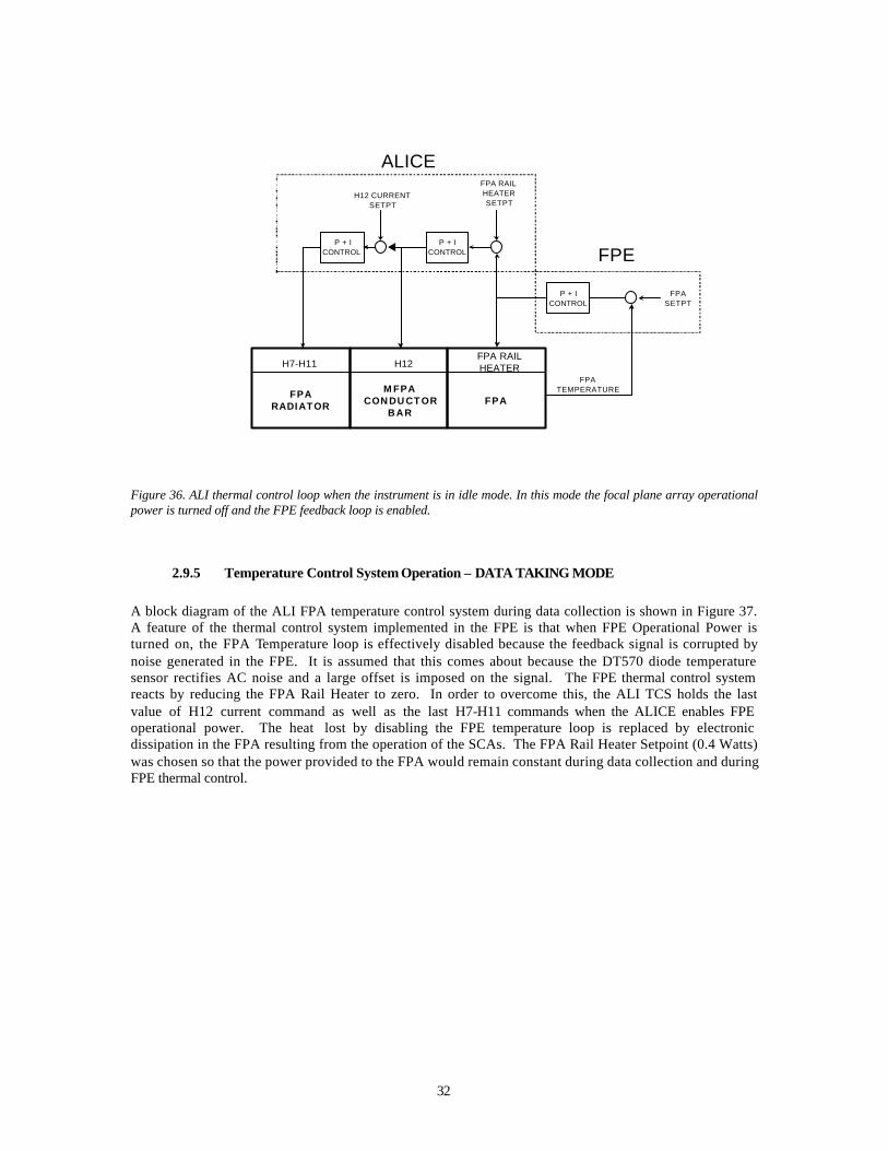
A block diagram of the ALI FPA temperature control system while the ALI is in idle mode (FPE operational power off) is shown in Figure 36. In this mode, the FPE regulates power to the FPA rail heater according to the difference between the FPA temperature and FPA temperature setpoint. If the FPA is too cold, power is applied to the FPA rail heater. Correspondingly, if the FPA is too warm, power to the FPA rail heater is removed. In a similar manner, power to the ALI TCS H12 heater is regulated according to the difference between the FPA rail heater power and FPA rail heater power setpoint. Finally, the ALI TCS FPA radiator heaters H7-11 are regulated based on the difference between the H12 current and H12 current setpoint. Monitoring and control of these loops are autonomously provided by ALICE.
32
Figure 36. ALI thermal control loop when the instrument is in idle mode. In this mode the focal plane array operational power is turned off and the FPE feedback loop is enabled.
2.9.5 Temperature Control System Operation – DATA TAKING MODE
A block diagram of the ALI FPA temperature control system during data collection is shown in Figure 37. A feature of the thermal control system implemented in the FPE is that when FPE Operational Power is turned on, the FPA Temperature loop is effectively disabled because the feedback signal is corrupted by noise generated in the FPE. It is assumed that this comes about because the DT570 diode temperature sensor rectifies AC noise and a large offset is imposed on the signal. The FPE thermal control system reacts by reducing the FPA Rail Heater to zero. In order to overcome this, the ALI TCS holds the last value of H12 current command as well as the last H7-H11 commands when the ALICE enables FPE operational power. The heat lost by disabling the FPE temperature loop is replaced by electronic dissipation in the FPA resulting from the operation of the SCAs. The FPA Rail Heater Setpoint (0.4 Watts) was chosen so that the power provided to the FPA would remain constant during data collection and during FPE thermal control.
MFPACONDUCTOR
BAR
FPARADIATOR FPA
H7-H11 H12FPA RAILHEATER
H12 CURRENTSETPT
FPA RAILHEATERSETPT
FPATEMPERATURE
FPASETPT
ALICE
FPE
P + ICONTROL
P + ICONTROL
P + ICONTROL
33
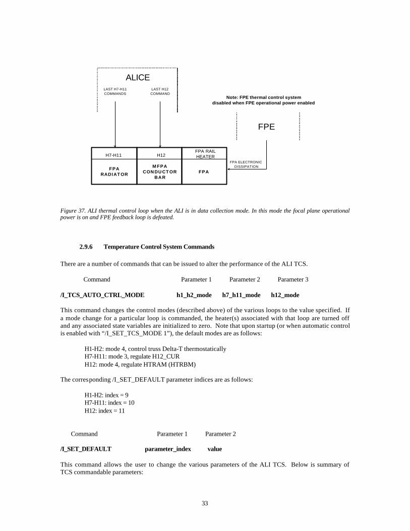
Figure 37. ALI thermal control loop when the ALI is in data collection mode. In this mode the focal plane operational power is on and FPE feedback loop is defeated.
2.9.6 Temperature Control System Commands
There are a number of commands that can be issued to alter the performance of the ALI TCS. Command Parameter 1 Parameter 2 Parameter 3 /I_TCS_AUTO_CTRL_MODE h1_h2_mode h7_h11_mode h12_mode This command changes the control modes (described above) of the various loops to the value specified. If a mode change for a particular loop is commanded, the heater(s) associated with that loop are turned off and any associated state variables are initialized to zero. Note that upon startup (or when automatic control is enabled with “/I_SET_TCS_MODE 1”), the default modes are as follows: H1-H2: mode 4, control truss Delta-T thermostatically H7-H11: mode 3, regulate H12_CUR H12: mode 4, regulate HTRAM (HTRBM) The corresponding /I_SET_DEFAULT parameter indices are as follows: H1-H2: index = 9 H7-H11: index = 10 H12: index = 11 Command Parameter 1 Parameter 2 /I_SET_DEFAULT parameter_index value This command allows the user to change the various parameters of the ALI TCS. Below is summary of TCS commandable parameters:
MFPACONDUCTOR
BAR
FPARADIATOR FPA
H7-H11 H12FPA RAILHEATER
FPA ELECTRONICDISSIPATION
ALICE
FPE
LAST H12COMMAND
LAST H7-H11COMMANDS
Note: FPE thermal control systemdisabled when FPE operational power enabled

34
H1-H2 startup mode /I_SET_DEFAULT index = 9, value = 4 H7-H11startup mode /I_SET_DEFAULT index = 10, value = 3 H12 startup mode /I_SET_DEFAULT index = 11, mode = 4
H1 turn-on threshold (mode 1, 3) /I_SET_DEFAULT index = 13, value = 162
H1 turn-off threshold (mode 1, 3)
/I_SET_DEFAULT index = 12, value = 185
H2 turn-on threshold (mode 2, 3) /I_SET_DEFAULT index = 15, value = 162
H2 turn-off threshold (mode 2, 3)
/I_SET_DEFAULT index = 14, value = 185 Delta-T turn-on threshold (mode 4)
/I_SET_DEFAULT index = 16, value = 18 Delta-T turn-off threshold (mode 4)
/I_SET_DEFAULT index = 17, value = 9 H7-H11 turn-on threshold (mode 1)
/I_SET_DEFAULT index = 19, value = 145 H7-H11 turn-off threshold (mode 1)
/I_SET_DEFAULT index = 18, value = 140
T34 Temperature Setpoint (H7-H11 mode 2) /I_SET_DEFAULT index = 20, value = 90
Temperature Control Proportional Gain (H7-H11 mode 2)
/I_SET_DEFAULT index =21, value = 10 Temperature Control Integral Gain (H7-H11 mode 2)
/I_SET_DEFAULT index = 22, value = 0 Temperature Control Interval (H7-H11 mode 2)
/I_SET_DEFAULT index = 99, value = 60 H12_CUR Moving Average Count (H7-H11 mode 3)
/I_SET_DEFAULT index = 106, value = 10
H12_CUR Current Setpoint (H7-H11 mode 3) /I_SET_DEFAULT index = 102, value = 139
H12 Power Control Proportional Gain (H7-H11 mode 3)
/I_SET_DEFAULT index = 103, value = 10 H12 Power Control Integral Gain (H7-H11 mode 3)
/I_SET_DEFAULT index = 104, value = 10
35
Maximum Heater Power Increase (H7-H11 mode 3) /I_SET_DEFAULT index = 113, value = 8
Maximum Heater Power Decrease (H7-H11 mode 3)
/I_SET_DEFAULT index = 114, value = 8
Heater Power Control Interval (H7-H11 mode 3) /I_SET_DEFAULT index = 101, value = 1200
H12 turn-on threshold (H12 mode 1)
/I_SET_DEFAULT index = 24, value = 60 H12 turn-off threshold (H12 mode 1)
/I_SET_DEFAULT index = 23, value = 52
T19 Temperature Setpoint (H12 mode 2) /I_SET_DEFAULT index = 25, value = 56
Temperature Control Proportional Gain (H12 mode 2)
/I_SET_DEFAULT index = 26, value = 100 Temperature Control Integral Gain (H12 mode 2)
/I_SET_DEFAULT index = 27, value = 10 HTRAM (HTRBM) Setpoint (H12 mode 3, 4)
/I_SET_DEFAULT index = 28, value = 78 Heater Power Control Proportional Gain (H12 mode 3, 4)
/I_SET_DEFAULT index = 29, value = 100 Heater Power Control Integral Gain (H12 mode 3, 4)
/I_SET_DEFAULT index = 30, value = 10 Heater Power Control Interval (H12 mode 3, 4)
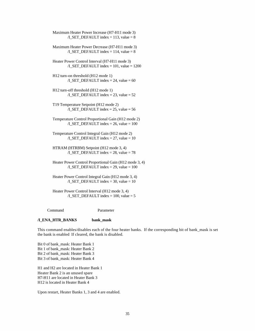
/I_SET_DEFAULT index = 100, value = 5 Command Parameter /I_ENA_HTR_BANKS bank_mask This command enables/disables each of the four heater banks. If the corresponding bit of bank_mask is set the bank is enabled If cleared, the bank is disabled. Bit 0 of bank_mask: Heater Bank 1 Bit 1 of bank_mask: Heater Bank 2 Bit 2 of bank_mask: Heater Bank 3 Bit 3 of bank_mask: Heater Bank 4 H1 and H2 are located in Heater Bank 1 Heater Bank 2 is an unused spare H7-H11 are located in Heater Bank 3 H12 is located in Heater Bank 4 Upon restart, Heater Banks 1, 3 and 4 are enabled.
36
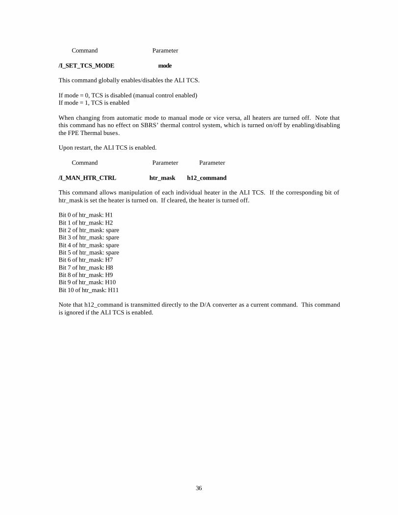
Command Parameter /I_SET_TCS_MODE mode This command globally enables/disables the ALI TCS. If mode = 0, TCS is disabled (manual control enabled) If mode = 1, TCS is enabled When changing from automatic mode to manual mode or vice versa, all heaters are turned off. Note that this command has no effect on SBRS’ thermal control system, which is turned on/off by enabling/disabling the FPE Thermal buses. Upon restart, the ALI TCS is enabled. Command Parameter Parameter /I_MAN_HTR_CTRL htr_mask h12_command This command allows manipulation of each individual heater in the ALI TCS. If the corresponding bit of htr_mask is set the heater is turned on. If cleared, the heater is turned off. Bit 0 of htr_mask: H1 Bit 1 of htr_mask: H2 Bit 2 of htr_mask: spare Bit 3 of htr_mask: spare Bit 4 of htr_mask: spare Bit 5 of htr_mask: spare Bit 6 of htr_mask: H7 Bit 7 of htr_mask: H8 Bit 8 of htr_mask: H9 Bit 9 of htr_mask: H10 Bit 10 of htr_mask: H11 Note that h12_command is transmitted directly to the D/A converter as a current command. This command is ignored if the ALI TCS is enabled.
37
3. INSTRUMENT ASSEMBLY AND ENGINEERING TEST RESULTS The flight telescope was delivered by SSG to MIT Lincoln Laboratory in April 1998. The Focal Plane System was delivered by SBRS in June 1998. ALI sub-systems were assembled, integrated, and tested over a 9-month period in preparation for delivery to the spacecraft integrator (Swales Aerospace) in March 1999. The integration and assembly followed a set of NASA processes specially tailored for the program quality control, documentation, and cleanliness of space-qualified components and sub-systems. During this time period testing was undertaken for subsystem alignment, for space flight qualification, and for performance measurement.
3.1 THERMAL AND MECHANICAL TESTING
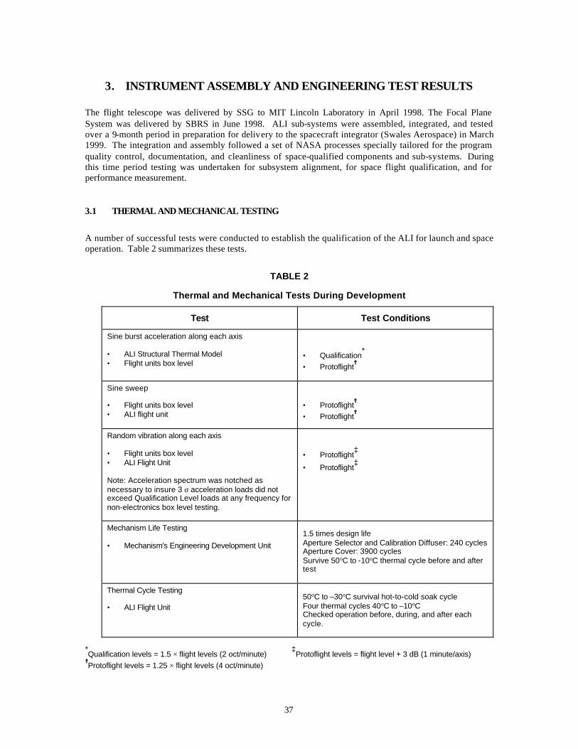
A number of successful tests were conducted to establish the qualification of the ALI for launch and space operation. Table 2 summarizes these tests.
TABLE 2
Thermal and Mechanical Tests During Development
Test Test Conditions
Sine burst acceleration along each axis • ALI Structural Thermal Model • Flight units box level
• Qualification*
• Protoflight=
Sine sweep • Flight units box level • ALI flight unit
• Protoflight=
• Protoflight=
Random vibration along each axis • Flight units box level • ALI Flight Unit Note: Acceleration spectrum was notched as necessary to insure 3 σ acceleration loads did not exceed Qualification Level loads at any frequency for non-electronics box level testing.
• Protoflight‡
• Protoflight‡
Mechanism Life Testing • Mechanism's Engineering Development Unit
1.5 times design life Aperture Selector and Calibration Diffuser: 240 cycles Aperture Cover: 3900 cycles Survive 50°C to -10°C thermal cycle before and after test
Thermal Cycle Testing • ALI Flight Unit
50°C to –30°C survival hot-to-cold soak cycle Four thermal cycles 40°C to –10°C Checked operation before, during, and after each cycle.
*Qualification levels = 1.5 × flight levels (2 oct/minute)
‡Protoflight levels = flight level + 3 dB (1 minute/axis)
=Protoflight levels = 1.25 × flight levels (4 oct/minute)
38
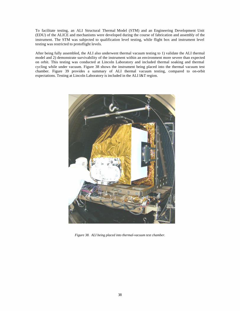
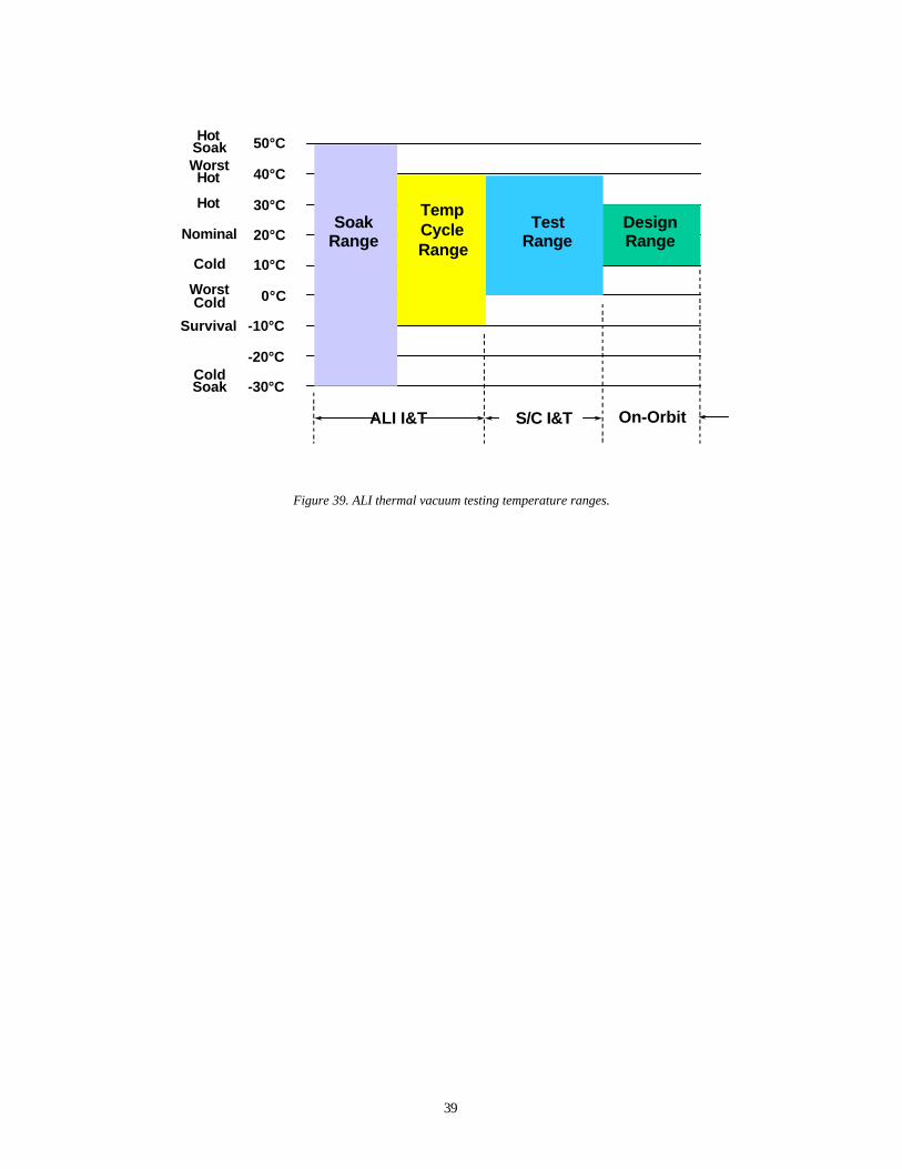
To facilitate testing, an ALI Structural Thermal Model (STM) and an Engineering Development Unit (EDU) of the ALICE and mechanisms were developed during the course of fabrication and assembly of the instrument. The STM was subjected to qualification level testing, while flight box and instrument level testing was restricted to protoflight levels. After being fully assembled, the ALI also underwent thermal vacuum testing to 1) validate the ALI thermal model and 2) demonstrate survivability of the instrument within an environment more severe than expected on orbit. This testing was conducted at Lincoln Laboratory and included thermal soaking and thermal cycling while under vacuum. Figure 38 shows the instrument being placed into the thermal vacuum test chamber. Figure 39 provides a summary of ALI thermal vacuum testing, compared to on-orbit expectations. Testing at Lincoln Laboratory is included in the ALI I&T region.
Figure 38. ALI being placed into thermal-vacuum test chamber.
39
Figure 39. ALI thermal vacuum testing temperature ranges.
50°C
40°C
30°C
20°C
10°C
0°C
-10°C
-20°C
-30°C
HotSoakWorstHot
Hot
Nominal
Cold
WorstCold
Survival
ColdSoak
ALI I&T On-OrbitS/C I&T
SoakRange
TempCycleRange
TestRange
DesignRange

40

41
4. ALI CALIBRATION The calibration and characterization plan for the ALI has both pre-launch and in-flight components6-12. The objectives are to characterize the overall instrument performance and to determine all instrument parameters required to generate accurate estimates of spatial, spectral and radiometric image quantities. The ALI performance requirements were guided by the Landsat 7 specification5 and were generated in concert with Landsat, EOS and EO-1 calibration scientists . The requirements were also constrained by the primary NMP mission objective, which is the validation of key technologies in flight. The instrument performance and verification tests included: measurements of noise, repeatability, polarization dependencies, temperature transient response, saturation recovery, image artifacts, and stray light rejection. The overall strategy is illustrated in Figure 40.
Figure 40. The EO-1 ALI pre-launch and post-launch calibration strategy.
The sensor calibration data comprise five measurement categories and are established for each detector channel (N). These are:
a) Normalized spectral response function: FN (λ)
This function represents the relative response of a detector channel to a constant monochromatic radiance (W/cm2
* sr * µm) at the entrance aperture of the sensor as a function of wavelength. The function is
normalized to unity at the peak. These functions define the in-band radiance L*λ at the entrance of the
sensor:
L*λ = ∫ L(λ)FN (λ)dλ , where L(λ) is the spectral radiance at the entrance of the sensor.
b) Pixel angular position in object space: (α,β)N
Pre Launch
•Component Tests and Analysis•Subsystem Measurements•System Level Measurements•Internal Source
•Internal Source•Solar Calibration•Lunar Scans•Earth Scenes
•Calibration Parameters•Performance Assessment
Calibration Pipeline Earth Scenes
Calibrated Data to Scientists
Post Launch
42
Each detector will respond to the radiance from different angular directions. This direction is determined both by the location of the detector in the focal plane of the telescope and the distortion from the optical system. Undistorted reconstruction of the scene requires accurate knowledge of the relative angular position of each detector in object space. These are measured relative to an arbitrary bore-sight direction.
c) Modulation transfer function: MTFN The MTF for each detector channel is a two dimensional function of spatial frequency. It represents the magnitude of the Fourier transform of the detector channel’s system response versus angle to a point source. The MTF is a measure of image sharpness and is used in quantitative image reconstruction.
d) Zero signal digital number offset: dno,
This is the digital number offset that each detector channel has when there is no input radiance. These offsets remain fairly constant, however they are measured for every data collection event to improve accuracy.
e) Response coefficient: CN, These convert raw digital numbers (dn) to estimates of in-band radiance (L*
λ), i.e., L*λ = CN (dn - dno).
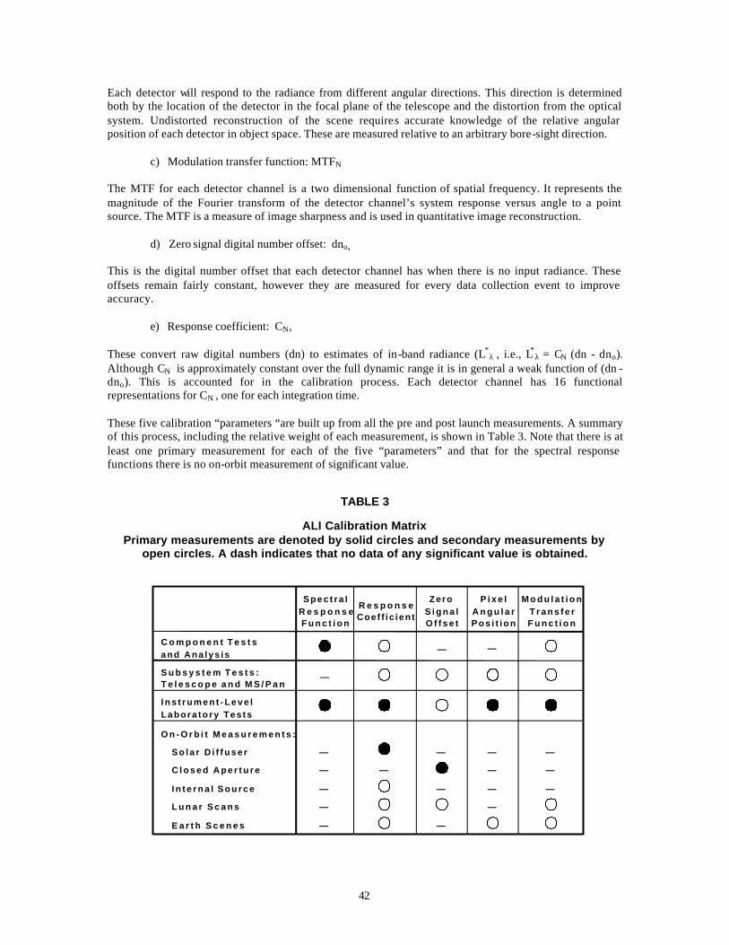
Although CN is approximately constant over the full dynamic range it is in general a weak function of (dn - dno). This is accounted for in the calibration process. Each detector channel has 16 functional representations for CN , one for each integration time. These five calibration “parameters “are built up from all the pre and post launch measurements. A summary of this process, including the relative weight of each measurement, is shown in Table 3. Note that there is at least one primary measurement for each of the five “parameters” and that for the spectral response functions there is no on-orbit measurement of significant value.
TABLE 3
ALI Calibration Matrix Primary measurements are denoted by solid circles and secondary measurements by
open circles. A dash indicates that no data of any significant value is obtained.
C o m p o n e n t T e s t sand Ana lys is
S p e c t r a lR e s p o n s eF u n c t i o n
R e s p o n s eCoef f ic ien t
ZeroS i g n a lO f f s e t
P i x e lA n g u l a rP o s i t i o n
M o d u l a t i o nT r a n s f e rF u n c t i o n
S u b s y s t e m T e s t s :T e l e s c o p e a n d M S / P a n
I n s t r u m e n t - L e v e lLabora to ry Tes ts
O n - O r b i t M e a s u r e m e n t s :
S o l a r D i f f u s e r
C l o s e d A p e r t u r e
I n t e r n a l S o u r c e
L u n a r S c a n s
E a r t h S c e n e s
—
— —
—
—
—
—
—
—
—
—
—
—
—
—
—
—
—
—
43
4.1 PRE-LAUNCH CALIBRATION AND CHARACTERIZATION STRATEGY
The pre-launch component, which is essentially completed, began with testing and analysis at the component level. This process continued through subsystem and system level testing. The objective was to generate initial estimates of the sensor’s spatial, spectral, and radiometric characteristics and then track the performance throughout the development phases of the instrument. This provided an early indication of any test setup errors, analysis errors, or performance anomalies. Moreover, since this process employed a number of independent and complementary calibration methods, consistency in projected performance increased the confidence of the final calibration parameters. Pre-launch testing and calibration were conducted under mission-like conditions including appropriate environmental conditions, and the full range of signal levels, wavelengths and spatial frequencies. The internal reference source was used throughout ground testing as a health check and to measure stability of performance. This was especially useful during environmental testing as a means of verifying satisfactory performance. Some measure of absolute radiometry is established for the internal reference source by transfer to the integrating sphere calibration. The design of the internal source is described in Section 2.3.
4.2 IN-FLIGHT CALIBRATION STRATEGY
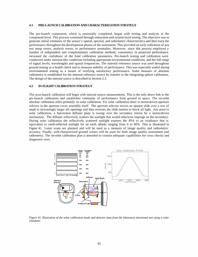
The post-launch calibration will begin with internal source measurements. This is the only direct link to the pre-launch calibration and establishes continuity of performance from ground to space. The on-orbit absolute calibration relies primarily on solar calibration. For solar calibration there is motor-driven aperture selector in the aperture cover assembly itself. The aperture selector moves an opaque slide over a row of small to increasingly larger slit openings and then reverses the slide motion to block all light. Just prior to solar calibration, a Spectralon diffuser plate is swung over the secondary mirror by a motor-driven mechanism. The diffuser reflectively scatters the sunlight that would otherwise impinge on the secondary. During solar calibration the reflectively scattered sunlight exposes the FPA to an irradiance that is equivalent to earth-reflected sunlight for an earth albedo ranging from 0 to 90%. This is illustrated in Figure 41. Lunar scans are planned and will be used as a measure of image quality and radiometric accuracy. Finally, well-characterized ground scenes will be used for both image quality assessment and radiometry. The on-orbit calibration plan is intended to contain adequate capabilities for cross checks and diagnostic tests.
1% 1%2% 3%7% 10%
20% 30%
20% 50%
20% 70%
20% 90%2.5"
2.5"
SignalLevel
Cumulative Signal
ApertureSelector
Diffuser Solar Beam
Cover
Scattered Light
Secondary
Figure 41. Illustration of the solar calibration mode and detector data from the laboratory functional test using a solar simulator.

44
Finally, the ALI will produce images that will be directly compared to those from the ETM+. The goal is to demonstrate that the ALI technology will provide data continuity with previous and current Landsat data. The EO-1 satellite will fly “in formation” with the Landsat 7 satellite in a sun-synchronous, 705 km, approximately 100 minute period orbit with a 10:01 am descending node. That is, it will be in an orbit that covers the same ground track as Landsat 7, approximately one minute later. The objective is to obtain images of the same ground areas at nearly the same time, so that scenes may be directly compared. It is planned that two to four scenes per day will be collected. Accordingly, the basic field of view, angular resolution, and spectral bands are matched to be as good or better than those of the ETM+.
45
5. CALIBRATION PIPELINE The ALI raw science data collected on orbit is downlinked and sent to Goddard Space Flight Center where it is converted to radiometrically calibrated data with engineering units of Wcm-2sr-1 by the calibration pipeline13. This section addresses the design and implementation of the pipeline, the initialization of the calibration database, the monitoring of system stability and handling of leaky pixel data anomalies by the software.
5.1 BACKGROUND
The ALI raw science data is downlinked, descrambled and arranged in imageable, band sequential order. This set of digital numbers, or raw sensor counts Cn, collected on orbit is referred to as the Level 0 science data. The radiometric calibration pipeline converts the Level 0 science data to the estimated in-band radiance L*
λ with engineering units of Wcm-2sr-1. This radiometrically calibrated data is referred to as the Level 1R science data. The simple equation defining the transform is:
L*λ = Rn(Cn-C0)
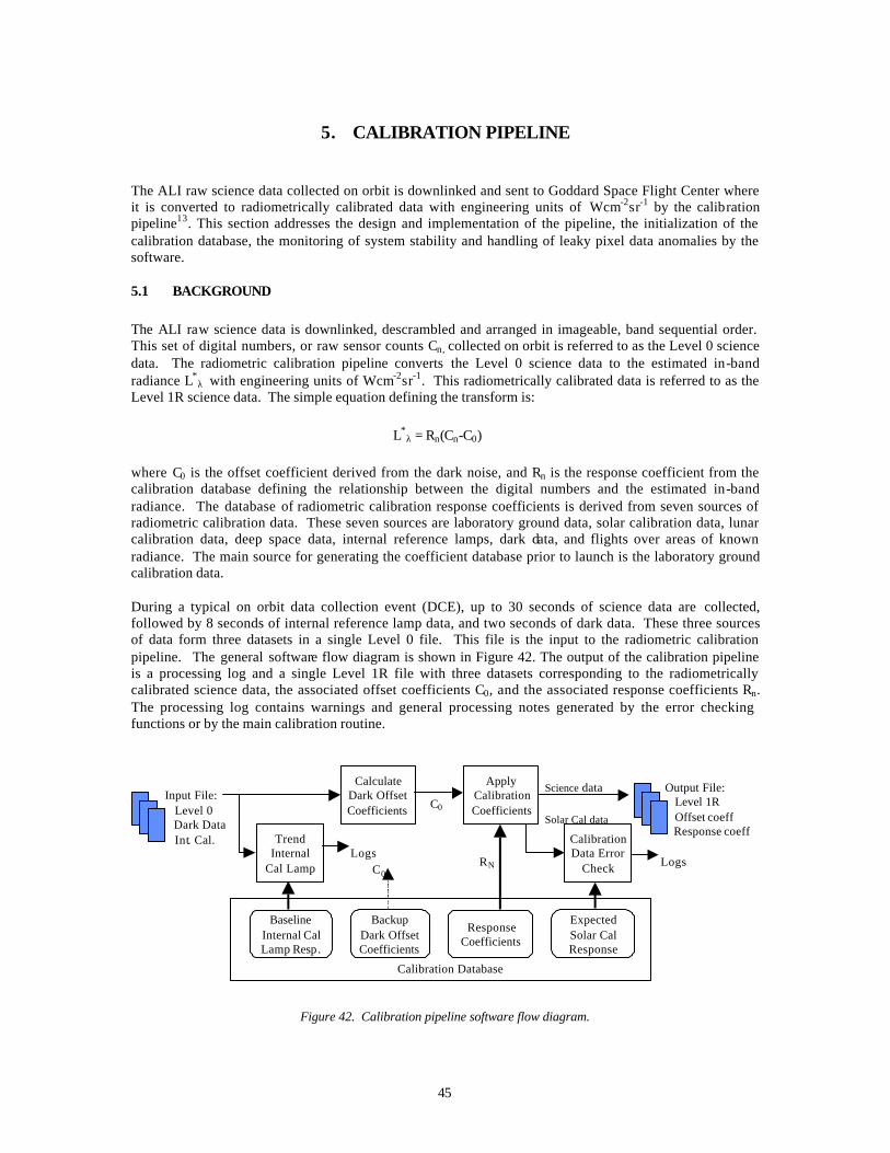
where C0 is the offset coefficient derived from the dark noise, and Rn is the response coefficient from the calibration database defining the relationship between the digital numbers and the estimated in-band radiance. The database of radiometric calibration response coefficients is derived from seven sources of radiometric calibration data. These seven sources are laboratory ground data, solar calibration data, lunar calibration data, deep space data, internal reference lamps, dark data, and flights over areas of known radiance. The main source for generating the coefficient database prior to launch is the laboratory ground calibration data. During a typical on orbit data collection event (DCE), up to 30 seconds of science data are collected, followed by 8 seconds of internal reference lamp data, and two seconds of dark data. These three sources of data form three datasets in a single Level 0 file. This file is the input to the radiometric calibration pipeline. The general software flow diagram is shown in Figure 42. The output of the calibration pipeline is a processing log and a single Level 1R file with three datasets corresponding to the radiometrically calibrated science data, the associated offset coefficients C0, and the associated response coefficients Rn. The processing log contains warnings and general processing notes generated by the error checking functions or by the main calibration routine.
BaselineInternal CalLamp Resp.
BackupDark OffsetCoefficients
ResponseCoefficients
ExpectedSolar CalResponse
Calibration Database
TrendInternal
Cal Lamp
Input File: Level 0 Dark Data Int. Cal.
Output File: Level 1R Offset coeff Response coeff
RN
C0
C0
CalibrationData Error
Check
ApplyCalibrationCoefficients
CalculateDark OffsetCoefficients
Science data
Solar Cal data
LogsLogs
Figure 42. Calibration pipeline software flow diagram.

46
The calibration pipeline depends heavily on the calibration database, which contains four datasets. The most important dataset is the set of calibration response coefficients Rn, which are used regularly for the primary calibration. The other datasets within the calibration pipeline database are a default set of offset coefficients, a baseline internal reference lamp dataset, and an expected solar response dataset. The offset coefficients, C0, are generally computed for each DCE from the dark data included in the Level 0 file. However, if for some reason dark data is not available for a single DCE or all DCEs, e.g., the instrument cover no longer closes, a set of default offset coefficients exists in the database. The internal reference lamp dataset that is collected along with each DCE is compared to the baseline internal reference lamp dataset. Any significant change in response is noted in the calibration pipeline’s processing log, and serves as a flag for detecting changes in the instrument. The expected solar calibration response dataset is used in a similar manner. The data collected during an on orbit solar calibration DCE will be radiometrically corrected using the calibration pipeline’s offset and response coefficients. The expected radiometric solar response is compared to the measured response with any significant variation noted in the calibration pipeline’s processing log.
5.2 INPUT/OUTPUT
The radiometric calibration pipeline is a stand alone, deliverable, software routine that receives Level 0 data as an input, performs the calibration, and outputs the Level 1R radiometrically calibrated data. Both the Level 0 data and the Level 1R data are available to various science teams performing data analysis in a distributed environment. Given the distributed work environment, the Hierarchical Data Format (HDF), created by the National Center for Supercomputing Applications (NCSA), was chosen for the file formats. HDF is self-describing, platform independent, and has supporting software for retrieval, storage, and visualization of the data, which makes the data easily readable by the distributed science teams. In addition to containing the basic science data, the Level 0 and Level 1R data files also contain most of the ancillary data needed for the basic science data processing. This ancillary data is stored in HDF fields called attributes. Each single Level 0 or Level 1R data file contains multiple datasets. Each file has a set of file attributes pertaining to that datafile and all of its datasets, e.g., file name, time of generation, and names of related files. Each dataset also has attributes with data parameters specific to that dataset, e.g., sensor used, dataset type, dimensions of dataset, integration time and frame rate. By using HDF and putting all of this information in a single, self-describing, platform independent file, any science team member is able to begin processing the data without further file format documentation. See Figure 43 for a depiction of a Level 0 file and content.
FilenameData Product LevelLZP Software version
ALI SensorDataset TypeData Start TimePercent Missing Data...
Dataset 1:
File Attributes
Science Data
Science Data Attrs
ALI SensorDataset Type# along track pixels# bands…
Dataset 2:
Dark Data
Dark Data Attrs
ALI SensorDataset TypeIntegration TimeFrame Rate…
Dataset 3:
Internal Lamp Data
Int. Lamp Data Attrs
Related File 1Related File 2...
Big or Little EndianTime of GenerationNumber Related Files
Figure 43. Sample HDF Level 0 file contents and structure.
47
5.3 CALIBRATION PIPELINE DATABASE
The radiometric calibration pipeline database is also an HDF file with multiple datasets. The primary dataset contains the response coefficients, with additional datasets for the default offset coefficients, the baseline internal reference lamp response, and the expected solar calibration response. A typical database HDF file attribute is when the database was generated. Database dataset HDF attributes include the time when the baseline internal reference lamp data was acquired, what files are the source of the default offset coefficients, and when the most recent on-orbit solar calibration data was acquired. The main source of data for generating the calibration database prior to launch is the ground calibration data collected in the laboratory. For initializing the calibration response coefficient database, a total of 440 useable datasets were collected in the laboratory. The datasets include 96 xenon lamp datasets for calibrating the three shortest wavelength VNIR bands (MS 1’, MS 1, and MS 2) and 344 halogen lamp datasets for the remaining VNIR (MS 3 MS 4, and MS 4’) and SWIR (MS 5’, MS 5, and MS 7.) Twelve different radiance levels were used, with the output of each level being monitored and recorded by a spectroradiometer. Three hundred and twelve of the datasets were recorded with the focal plane at the nominal operating temperature of 220 degree Kelvin, 64 datasets at 215 degree Kelvin, and 64 datasets at 225 degree Kelvin. The fourth variable was the integration time. The ALI integration times vary from 0 to 15, which correspond to 0.81 ms to 4.86 ms in steps of 0.27 ms. An integration time of 12 resulted in saturation for most bands at some radiance levels which completely exercised the full dynamic range of the focal plane.
5.4 MONITORING SYSTEM STABILITY
The radiometric calibration pipeline includes a function for monitoring the ALI stability using internal reference lamp data that will be collected on a regular basis. The internal reference lamp data was baselined prior to launch and will be trended over the course of the mission. The calibration pipeline will compare each new set of internal reference data to the baseline. If there is significant variation, a warning will be included in the calibration pipeline processing logs. The importance of the internal reference lamp data to the radiometric calibration pipeline is not for absolute radiometric calibration but for stability monitoring and overall performance assessment of the system. Additionally the mean and standard deviation of the dark data, which is collected with every DCE, is continuously being calculated when determining the offset coefficients C0. These numbers have been monitored throughout the I&T process, and will continue to be monitored on orbit to assure the system hasn’t changed.
5.5 LEAKY PIXEL ANOMALIES
During ground performance assessment of the system as a whole, two focal plane anomalies were discovered after application of the radiometric calibration pipeline. Leaky pixels were found on SCA 3, Band 3, detector/pixel 225 and on SCA 4, Band 2, detector/pixel 190. The focal plane electronics of the ALI are such that all even numbered detectors on a single SCA share a gate, and all odd numbered detectors share a gate. So an odd numbered leaky pixel such as pixel 225 manifests itself by leaking energy into all other odd numbered detectors or pixels on that band on that SCA and artificially raising the counts, Cn, seen on those detectors. Figure 44 is from the integration and test (I&T) imaging configuration using the Air Force image test reticle. The effect of Pixel 225 being illuminated and leaking into the other odd-numbered pixels is visible to the eye.
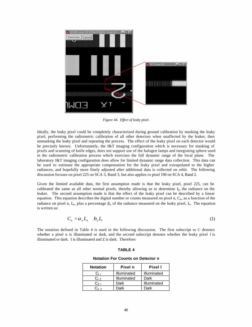
48
Figure 44. Effect of leaky pixel.
Ideally, the leaky pixel could be completely characterized during ground calibration by masking the leaky pixel, performing the radiometric calibration of all other detectors when unaffected by the leaker, then unmasking the leaky pixel and repeating the process. The effect of the leaky pixel on each detector would be precisely known. Unfortunately, the I&T imaging configuration which is necessary for masking of pixels and scanning of knife edges, does not support use of the halogen lamps and integrating sphere used in the radiometric calibration process which exercises the full dynamic range of the focal plane. The laboratory I&T imaging configuration does allow for limited dynamic range data collection. This data can be used to estimate the appropriate compensation for the leaky pixel and extrapolated to the higher radiances, and hopefully more finely adjusted after additional data is collected on orbit. The following discussion focuses on pixel 225 on SCA 3, Band 3, but also applies to pixel 190 on SCA 4, Band 2. Given the limited available data, the first assumption made is that the leaky pixel, pixel 225, can be calibrated the same as all other normal pixels, thereby allowing us to determine Ll, the radiance on the leaker. The second assumption made is that the effect of the leaky pixel can be described by a linear equation. This equation describes the digital number or counts measured on pixel n, Cn, as a function of the radiance on pixel n, Ln, plus a percentage βn of the radiance measured on the leaky pixel, Ll. The equation is written as:
lnnnn LLC βα += (1)
The notation defined in Table 4 is used in the following discussion. The first subscript to C denotes whether a pixel n is illuminated or dark, and the second subscript denotes whether the leaky pixel l is illuminated or dark. I is illuminated and Z is dark. Therefore:
TABLE 4
Notation For Counts on Detector n
Notation Pixel n Pixel l
CI I Illuminated Illuminated CI Z Illuminated Dark CZ I Dark Illuminated CZ Z Dark Dark
49
The other assumptions made are that Ln and Ll are either 0, or illuminated at a constant radiance of the same value. And since all processed data has been offset corrected, CZZ is considered to be 0. Given the above notations and assumptions, the equations are:
0
0
==
==
=
nnZZ
nnZI
nnn
l
LC
LCLC
thenL
if
α
αα (2)
Essentially, if the leaker is not illuminated, the counts on pixel n are purely a function of the radiance on pixel n and its radiometric coefficient, αn. If the leaker is illuminated, the following equations apply:
l
ZIIIn
lnZIII
lnnnII
LCC
LCC
LLC
−=
+=
+=
β
β
βα
(3)
and
l
ZZIZn
lnZZIZ
lnnnIZ
LCC
LCC
LLC
−=
+=
+=
β
β
βα
(4)
Essentially, the coefficient βn describing the amount of energy leaking from pixel l to pixel n can be estimated by determining the difference in counts with and without the leaky pixel illuminated, divided by the radiance on the leaky pixel. Data was collected with the I&T imaging configuration for the above 4 cases: pixel 225 dark, remaining pixels illuminated; pixel 225 illuminated, remaining pixels dark; all pixels illuminated; and all pixels dark. Given these four datasets, βn can be estimated with both equations (3) and (4). Results from these calculations agree to within 10% of each other. The difference in the estimates of βn indicates the amount of energy leaked from pixel 225 into the other pixels is not only a function of the radiance on pixel 225, but also a function of the radiance on the individual pixels. Initial analysis shows the higher the radiance on pixel n, the lesser the impact of leaky pixel 225 on the measured counts Cn. The first order linear approximation for βn can be used initially for the radiometric calibration, with attempts to more accurately determine the best correction after receiving more data collected on orbit (Figure 45).
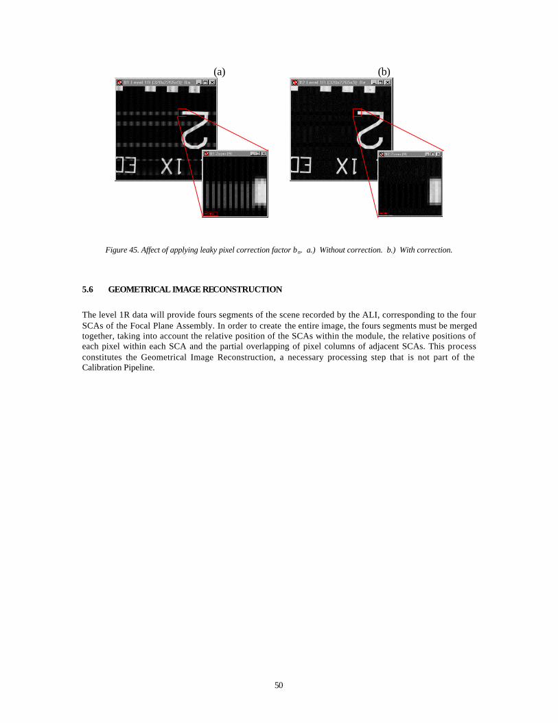
50
(a) (b)
Figure 45. Affect of applying leaky pixel correction factor βn. a.) Without correction. b.) With correction.
5.6 GEOMETRICAL IMAGE RECONSTRUCTION
The level 1R data will provide fours segments of the scene recorded by the ALI, corresponding to the four SCAs of the Focal Plane Assembly. In order to create the entire image, the fours segments must be merged together, taking into account the relative position of the SCAs within the module, the relative positions of each pixel within each SCA and the partial overlapping of pixel columns of adjacent SCAs. This process constitutes the Geometrical Image Reconstruction, a necessary processing step that is not part of the Calibration Pipeline.
51
6. COMMANDING THE ALI
The ALI has 37 basic commands. Each of these commands is uploaded to the spacecraft via the S-band transmitter to the Mongoose-V processor. The MV routes these commands to the ALICE RSN board via the 1773 fiber optic bus (see Section 2.8.5). The ASIST I_PROCESS_STAT window (Figure 49) displays various telemetry points that describe the status of the RSN: spacecraft time – indicating communication between the ALICE RSN and MV is operational, number of 1773 commands received since the last restart, number of 1773 retries, number of restarts since last power-up, and the functional code of the last command sent to the ALICE. Other pages of interest include the I_STORED_CMD and I_CMD_LOG. A description of each command, its functional code, related parameters, and the actions these commands produce are listed below.
6.1 COMMANDS
6.1.1 I_NOOP
No operation is initiated.
§ Function code: 00h § Parameters: none § Actions: none § Error codes: none
6.1.2 /I_DIAGMODE
Sets ALICE diagnostics mode.
§ Function code: 01h § Parameters:
- diag_mask Ø 0 = disable diagnostic packets Ø 1 = Dump Control Block Ø 2 = Dump Command Log Ø 3 = Dump Stored Command Queue Ø 4 = Dump Aperture Selector Resolver buffer (during extension) Ø 5 = Dump Aperture Selector Resolver buffer (during retraction)
§ Actions: - Updates control block Ø cb.diag_mode
§ Error codes: - Bad parameter -- error code = 5 Ø command ignored
6.1.3 /I_RST28VTRIPS
Resets specific +28 V protection circuit.
§ Function Code: 02h
52
§ Parameters: - circuit Ø bit 0: HOPA trip circuit Ø bit 1: Heater Bank 1 trip circuit Ø bit 2: Heater Bank 2 trip circuit Ø bit 3: Heater Bank 3 trip circuit Ø bit 4: Heater Bank 4 trip circuit Ø bit 5: Motor Power trip circuit Ø bit 6: FPE Power trip circuit 1 Ø bit 7: FPE Power trip circuit 2
§ Actions: - Clears, then sets, specified bits in MTCE_REG_2[0:5] - Sets, then clears, specified bits in MTCE_REG_2[6:7] Ø Note that FPE control bits are inverted, so actions are reversed
- Updates cb.trip_ckt_ena_status - Sets selected elements of cb.trip_state[:] to 0
§ Error codes: none
6.1.4 /I_DSBL28VTRIPS
Disables specific +28 V protection circuits.
§ Function Code: 03h § Parameters:
- circuit Ø bit 0: HOPA trip circuit Ø bit 1: Heater Bank 1 trip circuit Ø bit 2: Heater Bank 2 trip circuit Ø bit 3: Heater Bank 3 trip circuit Ø bit 4: Heater Bank 4 trip circuit Ø bit 5: Motor Power trip circuit Ø bit 6: FPE Power trip circuit 1 Ø bit 7: FPE Power trip circuit 2
§ Actions: - Clears specified bits in MTCE_REG_2[0:5] - Sets specified bits in MTCE_REG_2[6:7] - Updates control block Ø Note that FPE control bits are inverted, so actions are reversed
- Updates control block Ø cb.trip_ckt_ena_status
§ Error codes: none
6.1.5 /I_ENABLEPOKE
Enable memory poke.
§ Function Code: 04h § Parameters: none § Actions:
- Updates control block Ø cb.poke_status
§ Error codes: none
53
6.1.6 /I_POKE
Poke specific memory address.
§ Function Code: 05h § Parameters:
- address - value
§ Actions: - Writes the “value” to “address”; if writing to EEPROM, sets and resets wait states
appropriately Ø Note that EEPROM can be written to only when ALICE is connected to the GSE
box. Otherwise, the EEPROM is write protected - Disables poke by updating control block Ø cb.poke_status
§ Error codes: - Poke not enabled -- error code = 8 Ø command ignored
6.1.7 /I_ARMHOPA
Arm specific HOPA circuit.
§ Function Code: 06h § Parameters:
- circuit_mask Ø bit 0: HOPA circuit 1 --> CAL Launch Latch Ø bit 1: HOPA circuit 2 --> CAL Fail Safe Ø bit 2: HOPA circuit 3 --> TAC Launch Latch - A Ø bit 3: HOPA circuit 4 --> TAC Launch Latch - B Ø bit 4: HOPA circuit 5 --> TAC Fail Safe - A Ø bit 5: HOPA circuit 6 --> TAC Fail Safe -B
§ Actions: - Updates control block Ø cb.HOPA_arm_status
- Arms HOPA power by setting MTCE_REG_2[8] § Error codes:
- HOPA already armed -- error code = 9 Ø command ignored
- Bad parameter - Number of bits specified in “circuit_mask” not equal to one -- error code = 5 Ø command ignored
6.1.8 /I_FIREHOPA
Fire specific HOPA circuit for specified time period.
§ Function Code: 07h § Parameters:
- circuit_mask Ø bit 0: HOPA circuit 1 --> CAL Launch Latch Ø bit 1: HOPA circuit 2 --> CAL Fail Safe Ø bit 2: HOPA circuit 3 --> TAC Launch Latch - A
54
Ø bit 3: HOPA circuit 4 --> TAC Launch Latch - B Ø bit 4: HOPA circuit 5 --> TAC Fail Safe - A Ø bit 5: HOPA circuit 6 --> TAC Fail Safe –B
- DURATION Ø if = 0, energize HOPA for cb.defaults[HOPA_FIRE_DURATION_INDEX] Ø if <> 0, energize HOPA for specified number of seconds
§ Actions: - Schedules I_RESETHOPA command - Energizes HOPA power by setting bit in MTCE_REG_2[9:14] - Updates control block Ø cb.HOPA_fire_status Ø cb.hs_status Ø clears HOPA_OVERCURRENT bit Ø clears HOPA_ON_TOO_LONG bit Ø clears cb.HOPA_on_time
§ Error codes: - FIRE_HOPA_MASK does not match previously specified ARM_HOPA_MASK -- error
code = 5 Ø calls function that implements I_RESETHOPA -- rst_HOPA_ckts()
- HOPA already being fired -- error code = 10 Ø Command ignored
- HOPA not armed -- error code = 11 Ø Command ignored
- Scheduler error, stored command queue full -- error code = 7 Ø Command ignored
6.1.9 /I_RESETHOPA
Reset all HOPA circuits.
§ Function Code: 08h § Parameters: none § Actions: -
- Updates control block Ø clears cb.HOPA_arm_status Ø clears cb.HOPA_fire_status
- Disarms HOPA power by clearing MTCE_REG_2[8] - Deenergizes HOPA power by clearing MTCE_REG_2[9:14]
§ Error codes: none
6.1.10 /I_MECHPOWER
Enable mechanism power.
§ Function Code: 09h § Parameters: none § Actions:
- Updates control block Ø cb.mech_power
- Enables mechanism power by setting MTCE_REG_5[0] § Error codes: none
55
6.1.11 /I_MECHACTIVE
Activate specific mechanism in specific direction for specific number of steps.
§ Function Code: 0Ah § Parameters:
- direction Ø if = 0, open TAC, extend AS, place CAL Ø else, close TAC, retract AS, stow CAL
- mechanism Ø 0 = TAC, 1 = CAL, 2 = AS
- num_steps Ø if = 0, number of steps specified by
cb.defaults[TAC_MOTOR_STEPS_INDEX], cb.defaults[CAL_MOTOR_STEPS_INDEX] or cb.defaults[AS_MOTOR_STEPS_INDEX]
Ø if <> 0, step the specified number of steps § Actions:
- Updates control block Ø cb.motor_running Ø cb.active_motor Ø cb.motor_direction Ø cb.motor_steps Ø cb.motor_rate Ø cb.as_index Ø cb.as_counter Ø cb.motor_on_time Ø cb.hs_status
- clears MOTOR_OVERTEMP_MASK bit - clears MOTOR_OVERCURRENT_MASK bit - clears MOTOR_ON_TOO_LONG_MASK bit - Programs and starts Motor Control Task Timer
§ Error Codes: - Bad parameter, invalid mechanism ID -- error code = 5 Ø command ignored
- Mechanism power not enabled -- error code = 12 Ø command ignored
- Motor already active -- error code = 13 Ø command ignored
6.1.12 /I_MECHRESET
Reset all mechanisms.
§ Function Code: 0Bh § Parameters: none § Actions:
- Disables Motor Control Task Timer - Updates control block Ø cb.motor_running Ø cb.mech_power
- Disables motor power clearing MTCE_REG_5[0] - Turns off all motor phases by clearing MTCE_REG[1:4], MTCE_REG_5[5:8],
MTCE_REG_5[9:12]

56
§ Error codes: none
6.1.13 /I_LAMPENABLE
Enable internal lamp power.
§ Function Code: 0Ch § Parameters: none § Actions:
- Updates control block Ø cb.lamp_ena_status
- Enables all flood lamp circuits by clearing ASCE_REG_3[0:5] Ø Note that these are active low control signals
§ Error codes: none
6.1.14 /I_LAMPON
Power specific lamp for specific time period.
§ Function Code: 0Dh § Parameters:
- lamp_mask Ø bit 0: MFPA Flood Lamp A Ø bit 1: MFPA Flood Lamp B Ø bit 2: spare Ø bit 3: MFPA Flood Lamp C Ø bit 4: spare Ø bit 5: spare
- duration Ø if < 0: Turn on lamp indefinitely Ø if = 0: Turn on lamp for cb.defaults[LAMP_TIMER_INDEX] seconds Ø if > 0: Turn on lamp for specified number of seconds
§ Actions: - Schedules I_LAMPRESET ( if DURATION >= 0) - Updates control block Ø cb.lamp_ctl_status Ø if turning on lamps when all are off
clears LAMP_OVERCURRENT_MASK in cb.hs_status clears LAMP_ON_TOO_LONG_MASK in cb.hs_status initializes cb.lamp_on_time to zero
- Turns on specified lamps by clearing bits in ASCE_REG_3[8:13] Ø Note that these are active low control signals
§ Error codes: - Lamp power not enabled -- error code = 14 Ø Command ignored
- Bad parameter, more than three lamps specified -- error code = 5 Ø Command ignored
- Scheduler error, stored command queue full -- error code = 7 Ø Command ignored
57
6.1.15 /I_LAMPRESET
Reset all internal lamps.
§ Function Code: 0Eh § Parameters: none § Actions:
- Updates control block Ø cb.lamp_ena_status Ø cb.lamp_ctl_status
- Disables lamp power by setting ASCE_REG_3[0:5] - Turns off all lamps by setting ASCE_REG_3[8:13]
§ Error codes: none
6.1.16 /I_RESETFPE
Reset focal plane electronics.
§ Function Code: 0Fh § Parameters: none § Actions:
- Updates control block Ø sets cb.fpe_s_to_p_array[0:4] to 0 Ø sets cb.fpe_p_to_s_array[0:4] to 0
- If FPE data gate is on Ø Clears FPE Data Gate by clearing ESN_PORT_A[0] Ø updates cb.fpe_data_gate Ø updates cb.time_data_gate_cleared
- Clears FPE Reset line, ESN_PORT_A[1] Ø Note that FPE is an active low control signal
- Waits for 1 millisecond - Sets FPE Reset line, ESN_PORT_A[1]
§ Error codes: none
6.1.17 /I_SET_FPE_DG
Sets focal plane electronics data gate for specific time period.
§ Function Code: 10h § Parameters:
- duration Ø if < 0: Set FPE Data Gate indefinitely Ø if = 0, Set FPE Data Gate for DEFAULT_FPE_DG_DURATION seconds Ø if > 0, Set FPE Data Gate for specified number of seconds
§ Actions: - Schedule I_CLR_FPE_DG (if “duration” >= 0) - Updates control block Ø cb.time_data_gate_set Ø cb.fpe_data_gate
- Sets FPE Data Gate, ESN_PORT_A[0] § Error Codes:
- FPE Data Gate already set - error code = 16 Ø command ignored
58
- Scheduler error, too many stored commands - error code = 7 Ø command ignored
6.1.18 /I_CLR_FPE_DG
Resets focal plane electronics data gate.
§ Function Code: 11h § Parameters: none § Actions:
- Updates control block Ø cb.time_data_gate_cleared Ø cb.fpe_data_gate
- Clears FPE data gate , ESN_PORT_A[0] § Error Codes: none
6.1.19 /I_CONFIGFPE
Sends focal plane electronics configuration command.
§ Function Code: 12h § Parameters:
- config_command: Hex values as specified in FPE Interface Control Document Ø 0xxx: Null Command Ø 400x, 410x, 500x, 510x: Set PAN Integration Time Ø 420x, 430x, 520x, 530x: Set MS Integration Time Ø 6FFF, 7FFF: Enable Test Pattern Ø 6xxx, 7xxx ( ≠ 6FFF,7FFF): Disable Test Pattern Ø 8xxx, 9xxx: Set Line Rate Ø C100, D100: Enable MS/PAN Module Ø C101, D101: Disable MS/PAN Module
§ Actions: - Updates control block Ø cb.fpe_p_to_s_array[:], index depends on “config_command” Ø cb.fpe_s_to_p_array[:], index depends on “config_command” Ø cb.last_fpe_config_cmd Ø cb.last_fpe_loopback
- Sends “config_command” to FPE by writing to ESN Parallel-to-Serial converter hardware register
- Reads loopback from Serial-to-Parallel converter hardware register § Error Codes:
- Date gate is currently set - error code = 17 Ø Command Ignored
- Undefined command - error code = 5 Ø Command Ignored
- Loopback value does not match command value - error code = 18 Ø Error reported, no corrective measures taken, assume command received
6.1.20 /I_SETFPETHERM
Sets focal plane electronics thermal setpoint.

59
§ Function Code: 13h § Parameters:
- setpoint_mask Ø Bit 0: MFPA side A alternate setpoint 1 (225 deg K) Ø Bit 1: MFPA side A alternate setpoint 2 (215 deg K) Ø Bit 2: MFPA side B alternate setpoint 1 (210 deg K) Ø Bit 3: MFPA side B alternate setpoint 2 (205 deg K)
§ Actions: - Updates control block Ø cb.fpe_therm_sp
- Sets FPE thermal setpoints by writing to ESN_PORT_B[0:3] § Error Codes:
- Date gate is currently set - error code = 19 Ø Command Ignored
- Illegal combination of bits in mask, ( bit 0 and bit 1 ) or ( bit 2 and bit 3 )--- error code = 5 Ø Command Ignored
6.1.21 /I_SETFPEPOWER
Sets-up focal plane electronics and thermal control bus power.
§ Function Code: 14h § Parameters:
- power_mask Ø bit 0: FPE Operational Power Ø bit 1: unused Ø bit 2: FPE Thermal Control Bus A Ø bit 3: FPE Thermal Control Bus B
§ Actions: - Updates control block Ø cb.fpe_pwr_status Ø cb.hs_status
Clears FPE_OVERTEMPERATURE_MASK if previously unpowered Clears FPE_OVERCURRENT_MASK if previously unpowered Clears FPE_ON_TOO_LONG_MASK if turning on FPE operational Clears FPE_TCS_FAULT_MASK if turning on FPE Thermal Bus
Ø cb.fpe_on_time -- initializes to zero if turning on operational power Ø cb.fpe_offset_mode -- sets to 1 (enables FPE housekeeping offset calculation) if
turning off FPE operational, sets to 0 (disables) if turning off FPE operational - Schedules /I_RESETFPE for 2 seconds from the time command was executed - Enables/Disables FPE power as specified by writing to MTCE_REG_4[0:3]
§ Error Codes: - Illegal combination of bits in mask ( bit 2 and bit 3) -- error code = 5 Ø Command Ignored
- Stored command queue full, cannot schedule /I_RESETFPE -- error code = 7 Ø Command is executed anyway, error code reported in housekeeping
6.1.22 /I_SET_TCS_MODE
Set thermal control system mode.
§ Function Code: 15h
60
§ Parameters: - mode Ø 0: Manual control Ø else: Automatic control
§ Actions: - If not changing modes, no action taken - Turns off all heaters by clearing MTCE_REG_3[0:10] - Sets H12 current command to 0 by clearing MTCE_REG_0[0:11] - Updates control block Ø cb.heater_pwr_status Ø cb.h12_command Ø cb.therm_ctl_mode Ø If switching to automatic mode Ø cb.h1_h2_mode = cb.defaults[H1_H2_MODE_INDEX] Ø cb.h7_h11_mode = cb.defaults[H7_H11_MODE_INDEX] Ø cb.h12_mode = cb.defaults[H12_MODE_INDEX] Ø cb.h7_h11_command = 0 Ø cb.last_h7_h11_cmd = 0 Ø cb.last_h7_h11_error = 0 Ø cb.h7_h11_error = 0 Ø cb.tcs_interval_1 = 0 Ø cb.h12_command = 0 Ø cb.last_h12_cmd = 0 Ø cb.h12_error = 0 Ø cb.last_h12_error = 0
§ Error Codes: none
6.1.23 /I_ENA_HTR_BANKS
Set-up thermal control system heater banks power.
§ Function Code: 16h § Parameters:
- bank_mask Ø bit 0: Heater Bank 1 (HTR1 & HTR2) Ø bit 1: Heater Bank 2 (spare) Ø bit 2: Heater Bank 3 (HTR7-HTR11) Ø bit 3: Heater Bank 4 (HTR12)
- Actions: § Updates control block
Ø cb.htr_bank_status Ø cb.hs_status
Clears HB1_OVERCURRENT_MASK if enabling Heater Bank 1 Clears HB2_OVERCURRENT_MASK if enabling Heater Bank 2 Clears HB3_OVERCURRENT_MASK if enabling Heater Bank 3 Clears HB4_OVERCURRENT_MASK if enabling Heater Bank 4
- Enables / Disables heater banks as specified by writing MTCE_REG_3[11:14] § Error Codes: none
6.1.24 /I_MAN_HTR_CTRL
Set-up specific thermal control system manual heater control parameter.
61
§ Function Code: 17h § Parameters:
- htr_mask Ø bit 0:10, Heaters 1-11
- h12_command § Actions:
- Updates control block Ø cb.heater_pwr_status Ø cb.h12_command
- Turns on/off heaters by writing HTR_MASK to MTCE_REG_3[0:10] - Sets H12 current command by writing HTR12_CURRENT_COMMAND to
MTCE_REG_0[0:11] § Error Codes:
- Not in manual control mode - error code = 20 Ø Command ignored
6.1.25 /I_TCS_AUTO_CTRL_MODE
Set thermal control system auto control mode.
§ Function Code: 18h § Parameters:
- H1_H2_MODE Ø if 0: Disable HTR1 & HTR2 Ø if 1: Disable HTR2, Control HTR1 as thermostat Ø if 2: Disable HTR1, Control HTR2 as thermostat Ø if 3: Control HTR1 & HTR2 as thermostats Ø if 4-7: Control truss ∆ temperature
- H7_H11_MODE Ø if 0: Disable HTR7- HTR11 Ø if 1: Thermostatic Control of FPE Radiator Temperature Ø if 2: Proportional Control of FPE Radiator Temperature Ø if 3: Proportional Regulation of H12 Current
- H12_MODE Ø if 0: Disable HTR12 Ø if 1: Thermostatic Control of MFPA Conductor Bar Temperature Ø if 2: Proportional Control of MFPA Conductor Bar Temperature Ø if 3: Proportional Regulation of SBRS FPA Heater Power
- if 4: Proportional Regulation of SBRS FPE Heater Power with hold § Actions:
- Updates control block Ø if changing h1_h2_mode
cb.h1_h2_mode cb.heater_pwr_status -- turn off h1 and h2
Ø if changing h7_h11_mode cb.h7_h11_mode cb.heater_pwr_status -- turn off h7-h11 cb.h7_h11_command = 0 cb.last_h7_h11_cmd = 0 cb.last_h7_h11_error = 0 cb.h7_h11_error = 0 cb.tcs_interval_1 = 0
Ø if changing h12_mode cb.h12_mode

62
cb.h12_command = 0 cb.last_h12_cmd = 0 cb.h12_error = 0 cb.last_h12_error = 0
- For mode changes, associated heaters are turned off by writing to MTCE_REG_3[0:10], MTCE_REG_0[0:11]
§ Error Codes: - Not in automatic control mode - error code = 21 Ø Command ignored
- H1_H2_MODE > 4, H7_H11_MODE >3, H12_MODE > 4 - bad parameter -- error code = 5 Ø Command ignored
6.1.26 /I_EARTH_OBS
Activate Earth observation script.
§ Function Code: 19h § Parameters: none § Actions:
- Calls the function that implements I_SET_FPE_DG Ø “set_fpe_data_gate(-1)” -- data gate set indefinitely
- NOTE: commands are scheduled in reverse order, i.e. last command to be executed is scheduled first
- Schedules I_CLR_FPE_DG Ø execution time = current time + {EO_∆T_5_SECS, EO_∆T_5_SUBSECS }
- Schedules I_SET_FPE_DG Ø execution time = current time + {EO_∆T_4_SECS, EO_∆T_4_SUBSECS } Ø parameter 1 = -1, indefinitely
- Schedules I_MECHACTIVE Ø execution time = current time + {EO_∆T_3_SECS, EO_∆T_3_SUBSECS } Ø parameter 1 = 0, open Ø parameter 2 = 0, select TAC Ø parameter 3 = 0, default number of steps
- Schedules I_MECHPOWER Ø execution time = current time + {EO_∆T_2_SECS, EO_∆T_2_SUBSECS }
- Schedules I_CLR_FPE_DG Ø execution time = current time + {EO_∆T_1_SECS, EO_∆T_1_SUBSECS }
§ Error Codes: - Insufficient storage to schedule all commands - error code = 32 Ø command ignored
- Data gate already set - error code = 33 Ø command ignored
6.1.27 /I_FL_CAL
Activate internal lamp script.
§ Function Code: 1Ah § Parameters: none § Actions:
- Calls the function that implements I_LAMPENABLE Ø “ena_lamp_pwr()”

63
- NOTE: commands are scheduled in reverse order, i.e. last command to be executed is scheduled first
- Schedules I_CLR_FPE_DG Ø execution time = current_time + {FLC_∆T_6_SECS, FLC_∆T_6_SUBSECS}
- Schedules I_LAMPRESET Ø execution time = current_time + {FLC_∆T_5_SECS, FLC_∆T_5_SUBSECS}
- Schedules I_LAMPON Ø execution time = current_time + {FLC_∆T_4_SECS, FLC_∆T_4_SUBSECS} Ø parameter 1 = FLC_MASK_3 Ø parameter 2 = -1, indefinitely
- Schedules I_LAMPON Ø execution time = current_time + {FLC_∆T_3_SECS, FLC_∆T_3_SUBSECS} Ø parameter 1 = FLC_MASK_2 Ø parameter 2 = -1, indefinitely
- Schedules I_SET_FPE_DG Ø execution time = current_time + {FLC_∆T_2_SECS, FLC_∆T_2_SUBSECS} Ø parameter 1 = -1, indefinitely
- Schedules I_LAMPON Ø execution time = current_time + {FLC_∆T_1_SECS, FLC_∆T_1_SUBSECS} Ø parameter 1 = FLC_MASK_1 Ø parameter 2 = -1, indefinitely
§ Error Codes: - Insufficient storage to schedule all commands - error code = 48 Ø command ignored
6.1.28 /I_SOL_CAL
Activate solar calibration script.
§ Function Code: 1Bh § Parameters: none § Actions:
- Call function that implements /I_MECHPOWER Ø “ena_mech_pwr()”
- NOTE: commands are scheduled in reverse order, i.e. last command to be executed is scheduled first
- Schedules I_MECHACTIVE Ø execution time = current_time + {SOL_∆T_9_SECS, FLC_∆T_9_SUBSECS} Ø parameter 1 = 1, stow CAL plate Ø parameter 2 = 1, select CAL mechanism Ø parameter 3 = 0, default number of steps
- Schedules I_MECHPOWER Ø execution time = current_time + {SOL_∆T_8_SECS, FLC_∆T_8_SUBSECS}
- Schedules I_CLR_FPE_DG Ø execution time = current_time + {SOL_∆T_7_SECS, FLC_∆T_7_SUBSECS}
- Schedules I_MECHACTIVE Ø execution time = current_time + {SOL_∆T_6_SECS, FLC_∆T_6_SUBSECS} Ø parameter 1 = 1, retract AS blocker Ø parameter 2 = 2, select AS mechanism Ø parameter 3 = 0, default number of steps
- Schedules I_MECHPOWER Ø execution time = current_time + {SOL_∆T_5_SECS, FLC_∆T_5_SUBSECS}
- Schedules I_MECHACTIVE Ø execution time = current_time + {SOL_∆T_4_SECS, FLC_∆T_4_SUBSECS}

64
Ø parameter 1 = 0, extend AS blocker Ø parameter 2 = 2, select AS mechanism Ø parameter 3 = 0, default number of steps
- Schedules I_MECHPOWER Ø execution time = current_time + {SOL_∆T_3_SECS, FLC_∆T_3_SUBSECS}
- Schedules I_SET_FPE_DG Ø execution time = current_time + {SOL_∆T_2_SECS, FLC_∆T_2_SUBSECS} Ø parameter 1 = -1, indefinitely
- Schedules I_MECHACTIVE Ø execution time = current_time + {SOL_∆T_1_SECS, FLC_∆T_1_SUBSECS} Ø parameter 1 = 0, place CAL plate Ø parameter 2 = 1, CAL selected Ø parameter 3 = 0, default number of steps
§ Error Codes: - Insufficient storage to schedule all commands - error code = 64 Ø command ignored
6.1.29 /I_SET_DEFAULT
Set specific parameter default value.
§ Function Code: 1Ch § Parameters:
- param_index Ø See “Alice Parameter Descriptions” for details
- value Ø See “Alice Parameter Descriptions” for details
§ Actions: - Sets parameter to specified valued Ø cb.defaults[“param_index”] = “value”
§ Error Codes: - “param_index” out of range, error code = 5 ( greater than or equal to 120 and less than 0) Ø command ignored
- “value” out of range, error code = 5 (only for selected parameters, see “Alice Parameter Descriptions” for details) Ø command ignored
6.1.30 /I_FPE_OFFSET_MODE
Enable focal plane electronics housekeeping offset calculation.
§ Function Code: 1Dh § Parameters:
- ENABLE Ø 0: Disable calculation of FPE Housekeeping offset Ø else: Enable calculation of FPE Housekeeping offset
§ Actions: - Updates Control Block Ø cb.fpe_offset_mode
§ Error Codes: - None
65
6.1.31 /I_SET_FPE_ENA_MSPAN
Enable MSPAN module.
§ Function Code: 1Eh § Parameters:
- ENABLE Ø 0: Disable MS/PAN Ø else: Enable MS/PAN
§ Actions: - Issues I_CONFIGFPE command Ø /I_CONFIGFPE 0xC100 to enable Ø /I_CONFIGFPE 0xC101 to disable
§ Error Codes: - none, although errors may be generated by subsequent execution of I_CONFIGFPE
6.1.32 /I_SET_FPE_TEST_PATTERN
Enable test pattern mode.
§ Function Code: 1Fh § Parameters:
- ENABLE Ø 0: Disable Test Pattern Ø else: Enable Test Pattern
§ Actions: - Issues I_CONFIGFPE command Ø /I_CONFIGFPE 0x6FFF to enable Ø /I_CONFIGFPE 0x6000 to disable
§ Error Codes: - none, although errors may be generated by subsequent execution of I_CONFIGFPE
6.1.33 /I_SAFE_MODE
Activate safe mode script.
§ Function Code: 21h § Parameters:
- override Ø 0: Mechanism command scheduling is based on LED status Ø LED1 == 1 or LED2 == 1 schedules CAL commands Ø LED12 == 0 schedules AS commands Ø LED7 == 1 schedules TAC commands Ø else: Commands are unconditionally scheduled
§ Actions: - Clears cb.stored_cmd_count before scheduling mechanism commands - Calls the function that implements /I_LAMPRESET -- “rst_lamps()” Ø NOTE: commands are scheduled in reverse order, i.e. last command to be executed
is scheduled first - Schedules I_MECHACTIVE Ø execution time = current_time + {SAF_∆T_6_SECS, SAF_∆T_6_SUBSECS} Ø parameter 1 = 1: Stow CAL mechanism Ø parameter 2 = 1: Select CAL mechanism
66
Ø parameter 3 = 0: Step default number of steps - Schedules I_MECHPOWER Ø execution time = current_time + {SAF_∆T_5_SECS, SAF_∆T_5_SUBSECS}
- Schedules I_MECHACTIVE Ø execution time = current_time + {SAF_∆T_4_SECS, SAF_∆T_4_SUBSECS} Ø parameter 1 = 1: Stow AS mechanism Ø parameter 2 = 2: Select AS mechanism Ø parameter 3 = 0: Step default number of steps
- Schedules I_MECHPOWER Ø execution time = current_time + {SAF_∆T_3_SECS, SAF_∆T_3_SUBSECS}
- Schedules I_MECHACTIVE Ø execution time = current_time + {SAF_∆T_2_SECS, SAF_∆T_2_SUBSECS} Ø parameter 1 = 1: Close TAC Ø parameter 2 = 0: Select TAC mechanism Ø parameter 3 = 0: Step default number of steps
- Schedules I_MECHPOWER Ø execution time = current_time + {SAF_∆T_1_SECS, SAF_∆T_1_SUBSECS}
§ Error Codes: - None
6.1.34 /I_SCHED_CMD
Schedule a specific command to occur at a specific time.
§ Function Code: 30h § Parameters:
- cmd_id: any command that has been defined (except I_SCHED_CMD) - param1: must be included - param2: must be included - param3: must be included - {secs_msw, secs_lsw, subsecs_msw, subsecs_lsw}: 4 word time record containing
execution time § Actions:
- Inserts entry in stored command queue - Updates control block Ø cb.stored_cmd_cnt
§ Error Codes: - Execution time less than current time, error code = 6 Ø Command ignored
- Stored command queue full, error code = 7 Ø Command ignored
- Attempt was made to schedule I_SCHED_CMD, error code = 5 Ø Command ignored
6.1.35 /I_DEL_STORED_CMD
Delete a specific stored command.
§ Function Code: 31h § Parameters:
- STORED_CMD_ID § Actions:
- Removes the specified command from the stored command queue
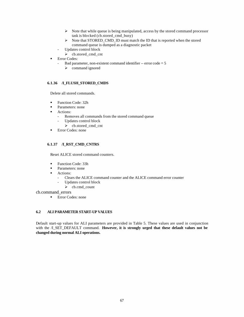
67
Ø Note that while queue is being manipulated, access by the stored command processor task is blocked (cb.stored_cmd_busy)
Ø Note that STORED_CMD_ID must match the ID that is reported when the stored command queue is dumped as a diagnostic packet
- Updates control block Ø cb.stored_cmd_cnt
§ Error Codes: - Bad parameter, non-existent command identifier -- error code = 5 Ø command ignored
6.1.36 /I_FLUSH_STORED_CMDS
Delete all stored commands.
§ Function Code: 32h § Parameters: none § Actions:
- Removes all commands from the stored command queue - Updates control block Ø cb.stored_cmd_cnt
§ Error Codes: none
6.1.37 /I_RST_CMD_CNTRS
Reset ALICE stored command counters.
§ Function Code: 33h § Parameters: none § Actions:
- Clears the ALICE command counter and the ALICE command error counter - Updates control block Ø cb.cmd_count
cb.command_errors § Error Codes: none
6.2 ALI PARAMETER START-UP VALUES
Default start-up values for ALI parameters are provided in Table 5. These values are used in conjunction with the /I_SET_DEFAULT command. However, it is strongly urged that these default values not be changed during normal ALI operations.

68
TABLE 5
Default ALI Start-up Parameters
Parameter Startup
Name Index Value Description HOPA_FIRE_DURATION 0 150 Duration (in seconds) of HOPA firing
must be > 0 TAC_MOTOR_STEPS 1 350 Number of steps taken when TAC is activated -
> 105 degrees CAL_MOTOR_STEPS 2 541 Number of steps taken when CAL is activated -
> 145 degrees AS_MOTOR_STEPS 3 3000 Number of steps taken when AS is activated -
> 3 inches TAC_MOTOR_RATE 4 2185 Time period between TAC steps ( divide by
65536 ) -> 30 Hz CAL_MOTOR_RATE 5 655 Time period between CAL steps ( divide by
65536 ) -> 110 Hz AS_MOTOR_RATE 6 341 Time period between AS steps ( divide by
65536 ) -> 192 Hz LAMP_TIMER_DURATION 7 2 Duration (in seconds) lamps are turned on
must be > 0 FPE_DG_DURATION 8 25 Duration (in seconds) data gate is set
must be > 0 H1_H2_MODE 9 4 H1-H2 Mode -> Control Truss Delta-T
must be >=0 and <=4 H7_H11_MODE 10 3 H7-H11 Mode -> Regulate H12 Power
must be >= 0 and <= 3 H12_MODE 11 4 H12 Mode -> Regulate FPA Rail Heater Power
must be >= 0 and <=4 H1_TSTAT_HI 12 185 Truss top plate turn-off threshold -> +30.2 deg
C (H1-H2 mode 1,3) H1_TSTAT_LO 13 162 Truss top plate turn-on threshold -> +20.1 deg
C (H1-H2 mode 1,3) H2_TSTAT_HI 14 185 Truss bottom plate turn-off threshold -> +30.2
deg C (H1-H2 mode 2,3) H2_TSTAT_LO 15 162 Truss bottom plate turn-on threshold -> +20.1
deg C (H1-H2 mode 2,3) H1_H2_DELTA_T_HI 16 18 Delta-T Turn-on threshold -> 7.88 deg C (H1-
H2 mode 4) H1_H2_DELTA_T_LO 17 9 Delta-T Turn-off threshold -> 3.94 deg C (H1-
H2 mode 4) H7_H11_TSTAT_HI 18 140 FPA Radiator Turn-off threshold -> -73.0 deg C
(H7-H11 mode 1) H7_H11_TSTAT_LO 19 145 FPA Radiator Turn-on threshold -> -74.2 deg C
(H7-H11 mode 1) H7_H11_T_SETPT 20 90 FPA Radiator Temperature Setpoint -> -60.1
deg C (H7-H11 mode 2) H7_H11_PROP_KP 21 10 FPA Radiator Temperature Loop Proportional
Gain (H7-H11 mode 2) H7_H11_PROP_KI 22 0 FPA Radiator Temperature Loop Integral Gain
(H7-H11 mode 2) H12_TSTAT_HI 23 52 MFPA Conductor Bar Turn-off threshold -
> -52.0 deg C (H12 mode 1) H12_TSTAT_LO 24 60 MFPA Conductor Bar Turn-on threshold -
> -53.9 deg C (H12 mode 1) H12_T_SETPT 25 56 MFPA Conductor Bar Temperature Setpoint -
> -52.9 deg C (H12 mode 2)

69
TABLE 5 (Continued)
Default ALI Start-up Parameters
Parameter Startup
Name Index Value Description H12_T_PROP_KP 26 100 MFPA Conductor Bar Temperature Loop
Proportional Gain (H12 mode 2) H12_T_PROP_KI 27 10 MFPA Conductor Bar Temperature Loop
Integral Gain (H12 mode 2) H12_Q_SETPT 28 78 FPA Rail Heater Power Setpoint -> -HTRAM
(HTRBM) = 9.09 (H12 mode 3,4) H12_Q_PROP_KP 29 100 FPA Rail Heater Power Loop Proportional Gain
(H12 mode 3, 4) H12_Q_PROP_KI 30 10 FPA Rail Heater Power Loop Integral Gain
(H12 mode 3,4) EO_DELTA_T_1_SECS 31 25 Delta seconds " /I_CLR_FPE_DG" is
scheduled after I_EARTH_OBS is executed --> FPE Data Gate is turned off, must be > 0 and < EO_DELTA_T_2_SECS
EO_DELTA_T_2_SECS 32 26 Delta seconds " /I_MECHPOWER" is scheduled after I_EARTH_OBS is executed --> Mechanism power is enabled, must be > EO_DELTA_T_1_SECS and < EO_DELTA_T_3_SECS
EO_DELTA_T_3_SECS 33 27 Delta seconds " /I_MECHACTIVE 1 0 0" is scheduled after I_EARTH_OBS is executed --> TAC closure is initiated, must be > EO_DELTA_T_2_SECS and < EO_DELTA_T_4_SECS
EO_DELTA_T_4_SECS 34 41 Delta seconds " /I_SET_FPE_DG -1" is scheduled after I_EARTH_OBS is executed --> FPE Data Gate is turned on for dark reference data, must be > EO_DELTA_T_3_SECS and < EO_DELTA_T_5_SECS
EO_DELTA_T_5_SECS 35 42 Delta seconds " /I_CLR_FPE_DG" is scheduled after I_EARTH_OBS is executed --> FPE Data Gate is turned off must be > EO_DELTA_T_4_SECS
EO_DELTA_T_1_SUBSECS 36 0 Delta subseconds (divide by 65535) added to EO_DELTA_T_1_SECS
EO_DELTA_T_2_SUBSECS 37 0 Delta subseconds (divide by 65535) added to EO_DELTA_T_2_SECS
EO_DELTA_T_3_SUBSECS 38 0 Delta subseconds (divide by 65535) added to EO_DELTA_T_3_SECS
EO_DELTA_T_4_SUBSECS 39 0 Delta subseconds (divide by 65535) added to EO_DELTA_T_4_SECS
EO_DELTA_T_5_SUBSECS 40 0 Delta subseconds (divide by 65535) added to EO_DELTA_T_5_SECS
FLC_DELTA_T_1_SECS 41 1 Delta seconds " /I_LAMPON cb.defaults[FLC_MASK_1] -1" is scheduled after I_FL_CAL is executed --> Flood Lamps specified in FLC_MASK_1 are turned on must be > 0 and < FLC_DELTA_T_2_SECS
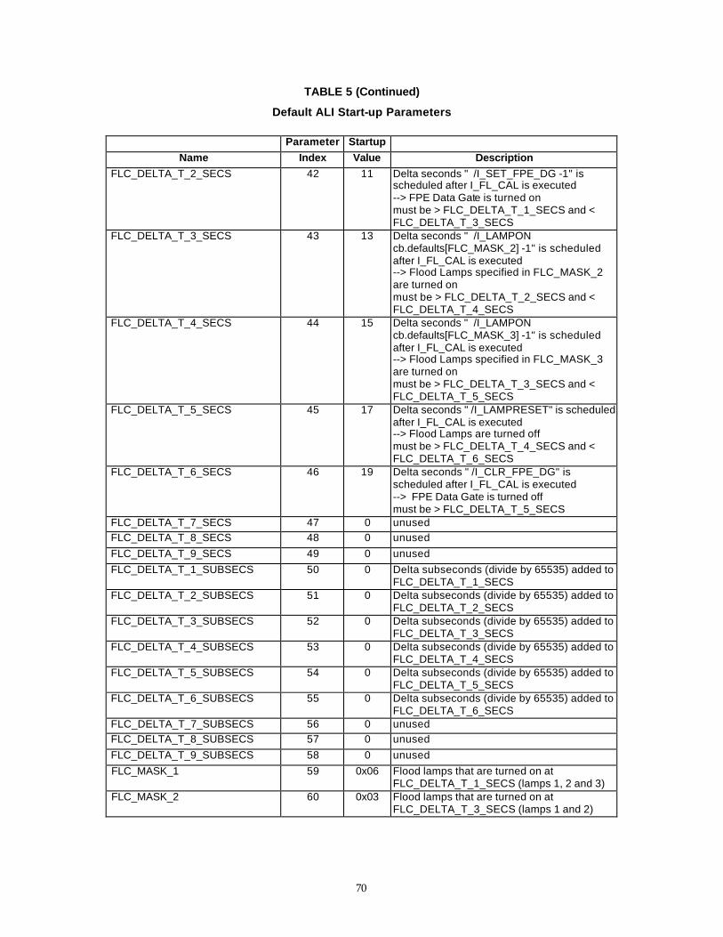
70
TABLE 5 (Continued)
Default ALI Start-up Parameters
Parameter Startup
Name Index Value Description FLC_DELTA_T_2_SECS 42 11 Delta seconds " /I_SET_FPE_DG -1" is
scheduled after I_FL_CAL is executed --> FPE Data Gate is turned on must be > FLC_DELTA_T_1_SECS and < FLC_DELTA_T_3_SECS
FLC_DELTA_T_3_SECS 43 13 Delta seconds " /I_LAMPON cb.defaults[FLC_MASK_2] -1" is scheduled after I_FL_CAL is executed --> Flood Lamps specified in FLC_MASK_2 are turned on must be > FLC_DELTA_T_2_SECS and < FLC_DELTA_T_4_SECS
FLC_DELTA_T_4_SECS 44 15 Delta seconds " /I_LAMPON cb.defaults[FLC_MASK_3] -1" is scheduled after I_FL_CAL is executed --> Flood Lamps specified in FLC_MASK_3 are turned on must be > FLC_DELTA_T_3_SECS and < FLC_DELTA_T_5_SECS
FLC_DELTA_T_5_SECS 45 17 Delta seconds " /I_LAMPRESET" is scheduled after I_FL_CAL is executed --> Flood Lamps are turned off must be > FLC_DELTA_T_4_SECS and < FLC_DELTA_T_6_SECS
FLC_DELTA_T_6_SECS 46 19 Delta seconds " /I_CLR_FPE_DG" is scheduled after I_FL_CAL is executed --> FPE Data Gate is turned off must be > FLC_DELTA_T_5_SECS
FLC_DELTA_T_7_SECS 47 0 unused
FLC_DELTA_T_8_SECS 48 0 unused
FLC_DELTA_T_9_SECS 49 0 unused
FLC_DELTA_T_1_SUBSECS 50 0 Delta subseconds (divide by 65535) added to FLC_DELTA_T_1_SECS
FLC_DELTA_T_2_SUBSECS 51 0 Delta subseconds (divide by 65535) added to FLC_DELTA_T_2_SECS
FLC_DELTA_T_3_SUBSECS 52 0 Delta subseconds (divide by 65535) added to FLC_DELTA_T_3_SECS
FLC_DELTA_T_4_SUBSECS 53 0 Delta subseconds (divide by 65535) added to FLC_DELTA_T_4_SECS
FLC_DELTA_T_5_SUBSECS 54 0 Delta subseconds (divide by 65535) added to FLC_DELTA_T_5_SECS
FLC_DELTA_T_6_SUBSECS 55 0 Delta subseconds (divide by 65535) added to FLC_DELTA_T_6_SECS
FLC_DELTA_T_7_SUBSECS 56 0 unused
FLC_DELTA_T_8_SUBSECS 57 0 unused
FLC_DELTA_T_9_SUBSECS 58 0 unused
FLC_MASK_1 59 0x06 Flood lamps that are turned on at FLC_DELTA_T_1_SECS (lamps 1, 2 and 3)
FLC_MASK_2 60 0x03 Flood lamps that are turned on at FLC_DELTA_T_3_SECS (lamps 1 and 2)

71
TABLE 5 (Continued)
Default ALI Start-up Parameters
Parameter Startup
Name Index Value Description FLC_MASK_3 61 0x01 Flood lamps that are turned on at
FLC_DELTA_T_4_SECS (lamp 1) FLC_MASK_4 62 0 unused
FLC_MASK_5 63 0 unused
FLC_MASK_6 64 0 unused
SOL_DELTA_T_1_SECS 65 1 Delta seconds "/I_MECHACTIVE 0 1 0" is scheduled after I_SOL_CAL is executed --> CAL deployment is initiated must be > 0 and < SOL_DELTA_T_2_SECS
SOL_DELTA_T_2_SECS 66 7 Delta seconds "/I_SET_FPE_DG -1" is scheduled after I_SOL_CAL is executed --> FPE Data Gate is turned on must be > SOL_DELTA_T_1_SECS and < SOL_DELTA_T_3_SECS
SOL_DELTA_T_3_SECS 67 8 Delta seconds "/I_MECHPOWER" is scheduled after I_SOL_CAL is executed --> Mechanism power is enabled must be > SOL_DELTA_T_2_SECS and < SOL_DELTA_T_4_SECS
SOL_DELTA_T_4_SECS 68 9 Delta seconds "/I_MECHACTIVE 0 2 0" is scheduled after I_SOL_CAL is executed --> AS Deployment is initiated must be > SOL_DELTA_T_3_SECS and < SOL_DELTA_T_5_SECS
SOL_DELTA_T_5_SECS 69 26 Delta seconds "/I_MECHPOWER" is scheduled after I_SOL_CAL is executed --> Mechanism power is enabled must be > SOL_DELTA_T_4_SECS and < SOL_DELTA_T_6_SECS
SOL_DELTA_T_6_SECS 70 27 Delta seconds "/I_MECHACTIVE 1 2 0" is scheduled after I_SOL_CAL is executed --> AS Stowage is initiated must be > SOL_DELTA_T_5_SECS and < SOL_DELTA_T_7_SECS
SOL_DELTA_T_7_SECS 71 44 Delta seconds "/I_CLR_FPE_DG" is scheduled after I_SOL_CAL is executed --> FPE Data Gate is turned off must be > SOL_DELTA_T_6_SECS and < SOL_DELTA_T_8_SECS
SOL_DELTA_T_8_SECS 72 45 Delta seconds " /I_MECHPOWER" is scheduled after I_SOL_CAL is executed --> Mechanism power is enabled must be > SOL_DELTA_T_7_SECS and < SOL_DELTA_T_9_SECS
SOL_DELTA_T_9_SECS 73 46 Delta seconds " /I_MECHACTIVE 1 1 0" is scheduled after I_SOL_CAL is executed --> CAL stowage is initiated must be > SOL_DELTA_T_8_SECS
SOL_DELTA_T_1_SUBSECS 74 0 Delta subseconds (divide by 65535) added to SOL_DELTA_T_1_SECS
SOL_DELTA_T_2_SUBSECS 75 0 Delta subseconds (divide by 65535) added to SOL_DELTA_T_2_SECS
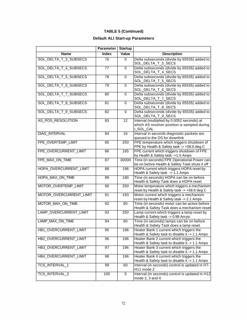
72
TABLE 5 (Continued)
Default ALI Start-up Parameters
Parameter Startup
Name Index Value Description SOL_DELTA_T_3_SUBSECS 76 0 Delta subseconds (divide by 65535) added to
SOL_DELTA_T_3_SECS SOL_DELTA_T_4_SUBSECS 77 0 Delta subseconds (divide by 65535) added to
SOL_DELTA_T_4_SECS SOL_DELTA_T_5_SUBSECS 78 0 Delta subseconds (divide by 65535) added to
SOL_DELTA_T_5_SECS SOL_DELTA_T_6_SUBSECS 79 0 Delta subseconds (divide by 65535) added to
SOL_DELTA_T_6_SECS SOL_DELTA_T_7_SUBSECS 80 0 Delta subseconds (divide by 65535) added to
SOL_DELTA_T_7_SECS SOL_DELTA_T_8_SUBSECS 81 0 Delta subseconds (divide by 65535) added to
SOL_DELTA_T_8_SECS SOL_DELTA_T_9_SUBSECS 82 0 Delta subseconds (divide by 65535) added to
SOL_DELTA_T_9_SECS AS_POS_RESOLUTION 83 12 Interval (multiplied by 0.0052 seconds) at
which AS resolver position is sampled during I_SOL_CAL
DIAG_INTERVAL 84 16 Interval in seconds diagnostic packets are queued to the OS for downlink
FPE_OVERTEMP_LIMIT 85 250 FPE temperature which triggers shutdown of FPE by Health & Safety task -> +58.6 deg C
FPE_OVERCURRENT_LIMIT 86 165 FPE current which triggers shutdown of FPE by Health & Safety task ->1.5 Amps
FPE_MAX_ON_TIME 87 30000 Time (in seconds) FPE Operational Power can be on before Health & Safety Task shuts it off
HOPA_OVERCURRENT_LIMIT 88 196 HOPA current which triggers HOPA reset by Health & Safety task -> 1.1 Amps
HOPA_MAX_ON_TIME 89 180 Time (in seconds) HOPA can be on before Health & Safety Task does a HOPA reset
MOTOR_OVERTEMP_LIMIT 90 250 Motor temperature which triggers a mechanism reset by Health & Safety task -> +58.6 deg C
MOTOR_OVERCURRENT_LIMIT 91 193 Motor current which triggers a mechanism reset by Health & Safety task -> 2.1 Amps
MOTOR_MAX_ON_TIME 92 60 Time (in seconds) motor can be active before Health & Safety Task does a mechanism reset
LAMP_OVERCURRENT_LIMIT 93 250 Lamp current which triggers a lamp reset by Health & Safety task -> 0.98 Am ps
LAMP_MAX_ON_TIME 94 60 Time (in seconds) lamps can be on before Health & Safety Task does a lamp reset
HB1_OVERCURRENT_LIMIT 95 196 Heater Bank 1 current which triggers the Health & Safety task to disable it -> 1.1 Amps
HB2_OVERCURRENT_LIMIT 96 196 Heater Bank 2 current which triggers the Health & Safety task to disable it -> 1.1 Amps
HB3_OVERCURRENT_LIMIT 97 196 Heater Bank 3 current which triggers the Health & Safety task to disable it -> 1.1 Amps
HB4_OVERCURRENT_LIMIT 98 196 Heater Bank 4 current which triggers the Health & Safety task to disable it -> 1.1 Amps
TCS_INTERVAL_1 99 60 Interval (in seconds) control is updated in H7-H11 mode 2
TCS_INTERVAL_2 100 5 Interval (in seconds) control is updated in H12 mode 2, 3 and 4
73
TABLE 5 (Continued)
Default ALI Start-up Parameters
Parameter Startup
Name Index Value Description TCS_INTERVAL_3 101 1200 Interval (in seconds) control is updated in H7-
H11 mode 3 H7_H11_Q_SETPT 102 139 MFPA Conductor Bar Heater Power Setpoint -
> 0.18 Amps (1.7 Watts) (H7-H11mode 3) H7_H11_Q_PROP_KP 103 10 MFPA Conductor Bar Heater Power Loop
Proportional Gain (H7-H11mode 3) H7_H11_Q_PROP_KI 104 10 MFPA Conductor Bar Heater Power Loop
Integral Gain (H7-H11mode 3) UNUSED 105 0 unused
H12_CUR_AVERAGE 106 10 Number of previous values of H12_CUR to be averaged in calculating the control in H7-H11 mode 3, must be > 0 and < 20
SAFE_DELTA_T_1_SECS 107 1 Delta seconds "/I_MECHPOWER" is scheduled after I_SAFE_MODE is executed --> Mechanism power is enabled must be > 0 and < SAFE_DELTA_T_2_SECS
SAFE_DELTA_T_2_SECS 108 2 Delta seconds "/I_MECHACTIVE 1 0 0" is scheduled after I_SAFE_MODE is executed --> TAC closure is initiated must be > SAFE_DELTA_T_1_SECS and < SAFE_DELTA_T_3_SECS
SAFE_DELTA_T_3_SECS 109 17 Delta seconds "/I_MECHPOWER" is scheduled after I_SAFE_MODE is executed --> Mechanism power is enabled must be > SAFE_DELTA_T_2_SECS and < SAFE_DELTA_T_4_SECS
SAFE_DELTA_T_4_SECS 110 18 Delta seconds "/I_MECHACTIVE 1 2 0" is scheduled after I_SAFE_MODE is executed --> AS Stowage is initiated must be > SAFE_DELTA_T_3_SECS and < SAFE_DELTA_T_5_SECS
SAFE_DELTA_T_5_SECS 111 34 Delta seconds "/I_MECHPOWER" is scheduled after I_SAFE_MODE is executed --> Mechanism power is enabled must be > SAFE_DELTA_T_4_SECS and < SAFE_DELTA_T_6_SECS
SAFE_DELTA_T_6_SECS 112 35 Delta seconds "/I_MECHACTIVE 1 1 0" is scheduled after I_SAFE_MODE is executed --> CAL stowage is initiated must be > SAFE_DELTA_T_5_SECS
MAX_H7_H11_CMD_INC 113 8 Maximum increase in H7-H11 command (bits) allowed during H7-H11 mode 3 control-> 6.4 Watts, must be > 0
MAX_H7_H11_CMD_DEC 114 8 Maximum decrease in H7-H11 command (bits) allowed during H7-H11 mode 3 control -> 6.4 Watts, must be > 0
HTRAM_HTRBM_OFF_LIMIT 115 10 FPA Rail Heater Power threshold which triggers the Health & Safety Task to turn off the FPE thermal control bus when FPE operational power is on --> HTRAM (HTRBM) = 1.2 V (0.01 W)
TRIP_SAFE_TIME 116 10 Interval in seconds trip state is reset to zero
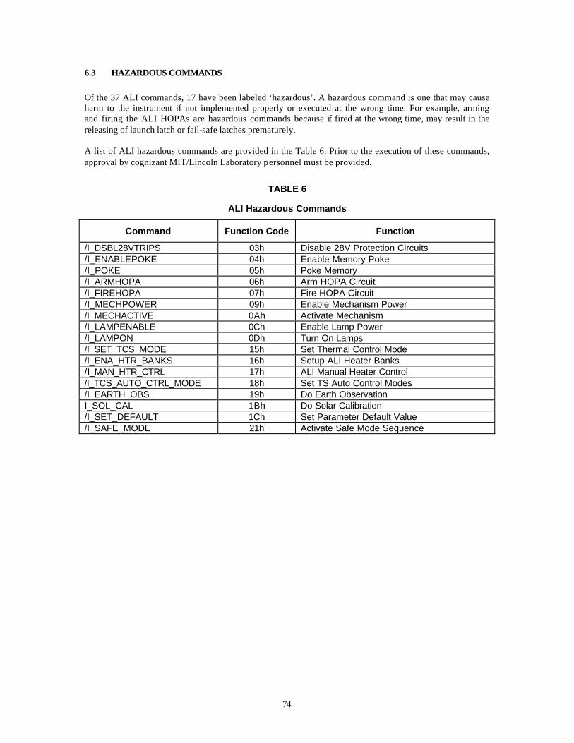
74
6.3 HAZARDOUS COMMANDS
Of the 37 ALI commands, 17 have been labeled ‘hazardous’. A hazardous command is one that may cause harm to the instrument if not implemented properly or executed at the wrong time. For example, arming and firing the ALI HOPAs are hazardous commands because if fired at the wrong time, may result in the releasing of launch latch or fail-safe latches prematurely. A list of ALI hazardous commands are provided in the Table 6. Prior to the execution of these commands, approval by cognizant MIT/Lincoln Laboratory personnel must be provided.
TABLE 6
ALI Hazardous Commands
Command Function Code Function
/I_DSBL28VTRIPS 03h Disable 28V Protection Circuits /I_ENABLEPOKE 04h Enable Memory Poke /I_POKE 05h Poke Memory /I_ARMHOPA 06h Arm HOPA Circuit /I_FIREHOPA 07h Fire HOPA Circuit /I_MECHPOWER 09h Enable Mechanism Power /I_MECHACTIVE 0Ah Activate Mechanism /I_LAMPENABLE 0Ch Enable Lamp Power /I_LAMPON 0Dh Turn On Lamps /I_SET_TCS_MODE 15h Set Thermal Control Mode /I_ENA_HTR_BANKS 16h Setup ALI Heater Banks /I_MAN_HTR_CTRL 17h ALI Manual Heater Control /I_TCS_AUTO_CTRL_MODE 18h Set TS Auto Control Modes /I_EARTH_OBS 19h Do Earth Observation I_SOL_CAL 1Bh Do Solar Calibration /I_SET_DEFAULT 1Ch Set Parameter Default Value /I_SAFE_MODE 21h Activate Safe Mode Sequence
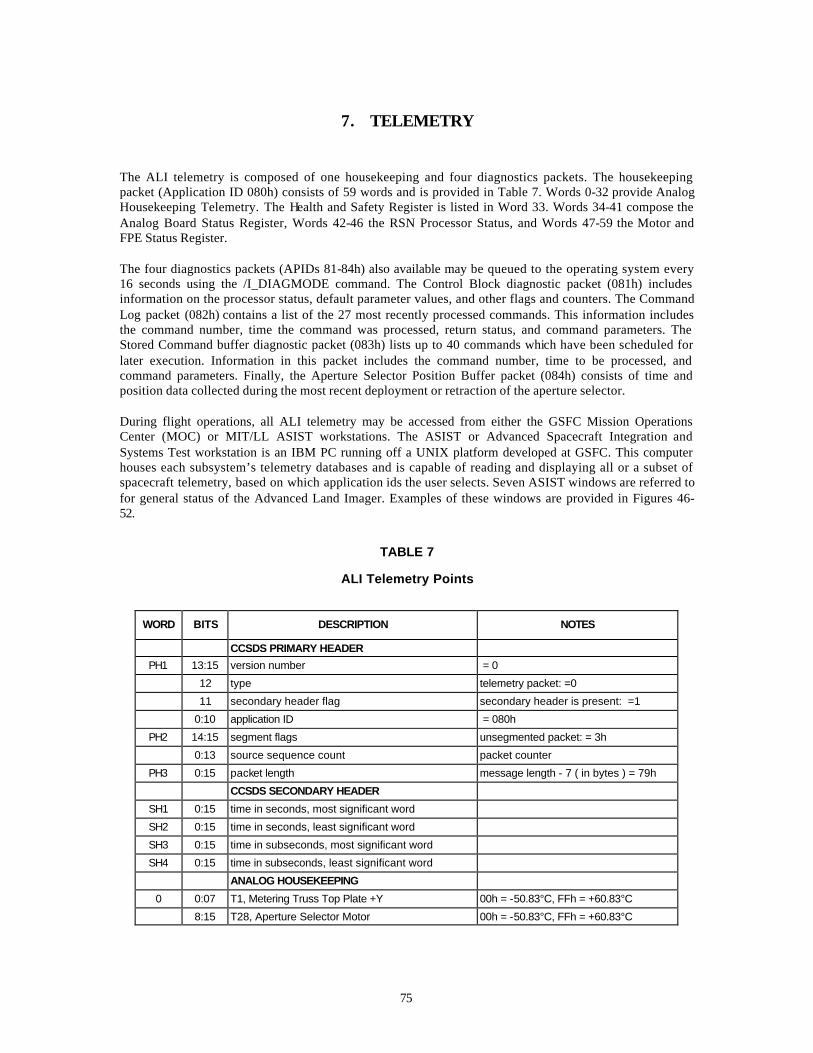
75
7. TELEMETRY The ALI telemetry is composed of one housekeeping and four diagnostics packets. The housekeeping packet (Application ID 080h) consists of 59 words and is provided in Table 7. Words 0-32 provide Analog Housekeeping Telemetry. The Health and Safety Register is listed in Word 33. Words 34-41 compose the Analog Board Status Register, Words 42-46 the RSN Processor Status, and Words 47-59 the Motor and FPE Status Register. The four diagnostics packets (APIDs 81-84h) also available may be queued to the operating system every 16 seconds using the /I_DIAGMODE command. The Control Block diagnostic packet (081h) includes information on the processor status, default parameter values, and other flags and counters. The Command Log packet (082h) contains a list of the 27 most recently processed commands. This information includes the command number, time the command was processed, return status, and command parameters. The Stored Command buffer diagnostic packet (083h) lists up to 40 commands which have been scheduled for later execution. Information in this packet includes the command number, time to be processed, and command parameters. Finally, the Aperture Selector Position Buffer packet (084h) consists of time and position data collected during the most recent deployment or retraction of the aperture selector. During flight operations, all ALI telemetry may be accessed from either the GSFC Mission Operations Center (MOC) or MIT/LL ASIST workstations. The ASIST or Advanced Spacecraft Integration and Systems Test workstation is an IBM PC running off a UNIX platform developed at GSFC. This computer houses each subsystem’s telemetry databases and is capable of reading and displaying all or a subset of spacecraft telemetry, based on which application ids the user selects. Seven ASIST windows are referred to for general status of the Advanced Land Imager. Examples of these windows are provided in Figures 46-52.
TABLE 7
ALI Telemetry Points
WORD BITS DESCRIPTION NOTES
CCSDS PRIMARY HEADER
PH1 13:15 version number = 0
12 type telemetry packet: =0
11 secondary header flag secondary header is present: =1
0:10 application ID = 080h
PH2 14:15 segment flags unsegmented packet: = 3h
0:13 source sequence count packet counter
PH3 0:15 packet length message length - 7 ( in bytes ) = 79h
CCSDS SECONDARY HEADER
SH1 0:15 time in seconds, most significant word
SH2 0:15 time in seconds, least significant word
SH3 0:15 time in subseconds, most significant word
SH4 0:15 time in subseconds, least significant word
ANALOG HOUSEKEEPING
0 0:07 T1, Metering Truss Top Plate +Y 00h = -50.83°C, FFh = +60.83°C
8:15 T28, Aperture Selector Motor 00h = -50.83°C, FFh = +60.83°C
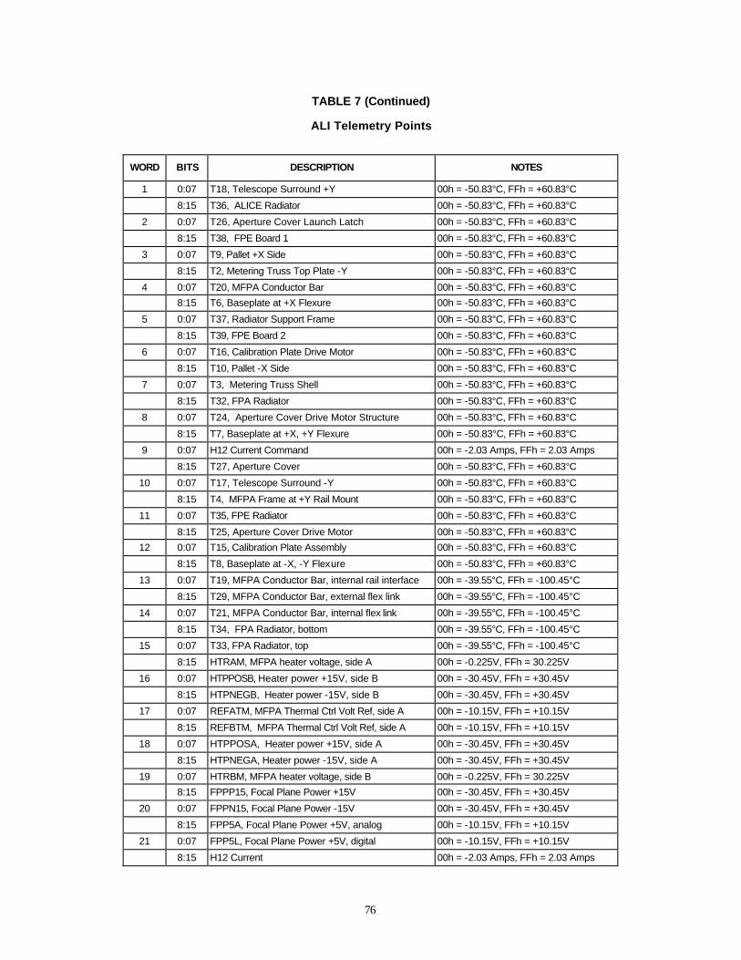
76
TABLE 7 (Continued)
ALI Telemetry Points
WORD BITS DESCRIPTION NOTES
1 0:07 T18, Telescope Surround +Y 00h = -50.83°C, FFh = +60.83°C
8:15 T36, ALICE Radiator 00h = -50.83°C, FFh = +60.83°C
2 0:07 T26, Aperture Cover Launch Latch 00h = -50.83°C, FFh = +60.83°C
8:15 T38, FPE Board 1 00h = -50.83°C, FFh = +60.83°C
3 0:07 T9, Pallet +X Side 00h = -50.83°C, FFh = +60.83°C
8:15 T2, Metering Truss Top Plate -Y 00h = -50.83°C, FFh = +60.83°C
4 0:07 T20, MFPA Conductor Bar 00h = -50.83°C, FFh = +60.83°C
8:15 T6, Baseplate at +X Flexure 00h = -50.83°C, FFh = +60.83°C
5 0:07 T37, Radiator Support Frame 00h = -50.83°C, FFh = +60.83°C
8:15 T39, FPE Board 2 00h = -50.83°C, FFh = +60.83°C
6 0:07 T16, Calibration Plate Drive Motor 00h = -50.83°C, FFh = +60.83°C
8:15 T10, Pallet -X Side 00h = -50.83°C, FFh = +60.83°C
7 0:07 T3, Metering Truss Shell 00h = -50.83°C, FFh = +60.83°C
8:15 T32, FPA Radiator 00h = -50.83°C, FFh = +60.83°C
8 0:07 T24, Aperture Cover Drive Motor Structure 00h = -50.83°C, FFh = +60.83°C
8:15 T7, Baseplate at +X, +Y Flexure 00h = -50.83°C, FFh = +60.83°C
9 0:07 H12 Current Command 00h = -2.03 Amps, FFh = 2.03 Amps
8:15 T27, Aperture Cover 00h = -50.83°C, FFh = +60.83°C
10 0:07 T17, Telescope Surround -Y 00h = -50.83°C, FFh = +60.83°C
8:15 T4, MFPA Frame at +Y Rail Mount 00h = -50.83°C, FFh = +60.83°C
11 0:07 T35, FPE Radiator 00h = -50.83°C, FFh = +60.83°C
8:15 T25, Aperture Cover Drive Motor 00h = -50.83°C, FFh = +60.83°C
12 0:07 T15, Calibration Plate Assembly 00h = -50.83°C, FFh = +60.83°C
8:15 T8, Baseplate at -X, -Y Flexure 00h = -50.83°C, FFh = +60.83°C
13 0:07 T19, MFPA Conductor Bar, internal rail interface 00h = -39.55°C, FFh = -100.45°C
8:15 T29, MFPA Conductor Bar, external flex link 00h = -39.55°C, FFh = -100.45°C
14 0:07 T21, MFPA Conductor Bar, internal flex link 00h = -39.55°C, FFh = -100.45°C
8:15 T34, FPA Radiator, bottom 00h = -39.55°C, FFh = -100.45°C
15 0:07 T33, FPA Radiator, top 00h = -39.55°C, FFh = -100.45°C
8:15 HTRAM, MFPA heater voltage, side A 00h = -0.225V, FFh = 30.225V
16 0:07 HTPPOSB, Heater power +15V, side B 00h = -30.45V, FFh = +30.45V
8:15 HTPNEGB, Heater power -15V, side B 00h = -30.45V, FFh = +30.45V
17 0:07 REFATM, MFPA Thermal Ctrl Volt Ref, side A 00h = -10.15V, FFh = +10.15V
8:15 REFBTM, MFPA Thermal Ctrl Volt Ref, side A 00h = -10.15V, FFh = +10.15V
18 0:07 HTPPOSA, Heater power +15V, side A 00h = -30.45V, FFh = +30.45V
8:15 HTPNEGA, Heater power -15V, side A 00h = -30.45V, FFh = +30.45V
19 0:07 HTRBM, MFPA heater voltage, side B 00h = -0.225V, FFh = 30.225V
8:15 FPPP15, Focal Plane Power +15V 00h = -30.45V, FFh = +30.45V
20 0:07 FPPN15, Focal Plane Power -15V 00h = -30.45V, FFh = +30.45V
8:15 FPP5A, Focal Plane Power +5V, analog 00h = -10.15V, FFh = +10.15V
21 0:07 FPP5L, Focal Plane Power +5V, digital 00h = -10.15V, FFh = +10.15V
8:15 H12 Current 00h = -2.03 Amps, FFh = 2.03 Amps
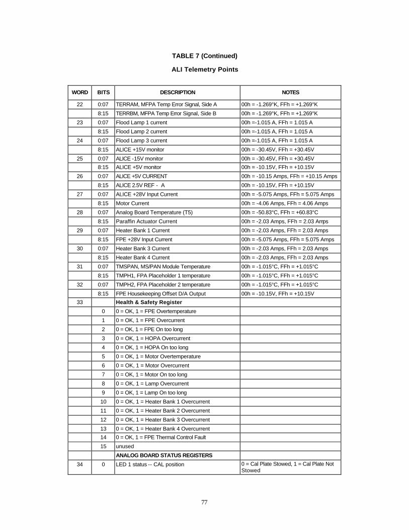
77
TABLE 7 (Continued)
ALI Telemetry Points
WORD BITS DESCRIPTION NOTES
22 0:07 TERRAM, MFPA Temp Error Signal, Side A 00h = -1.269°K, FFh = +1.269°K
8:15 TERRBM, MFPA Temp Error Signal, Side B 00h = -1.269°K, FFh = +1.269°K
23 0:07 Flood Lamp 1 current 00h =-1.015 A, FFh = 1.015 A
8:15 Flood Lamp 2 current 00h =-1.015 A, FFh = 1.015 A
24 0:07 Flood Lamp 3 current 00h =-1.015 A, FFh = 1.015 A
8:15 ALICE +15V monitor 00h = -30.45V, FFh = +30.45V
25 0:07 ALICE -15V monitor 00h = -30.45V, FFh = +30.45V
8:15 ALICE +5V monitor 00h = -10.15V, FFh = +10.15V
26 0:07 ALICE +5V CURRENT 00h = -10.15 Amps, FFh = +10.15 Amps
8:15 ALICE 2.5V REF - A 00h = -10.15V, FFh = +10.15V
27 0:07 ALICE +28V Input Current 00h = -5.075 Amps, FFh = 5.075 Amps
8:15 Motor Current 00h = -4.06 Amps, FFh = 4.06 Amps
28 0:07 Analog Board Temperature (T5) 00h = -50.83°C, FFh = +60.83°C
8:15 Paraffin Actuator Current 00h = -2.03 Amps, FFh = 2.03 Amps
29 0:07 Heater Bank 1 Current 00h = -2.03 Amps, FFh = 2.03 Amps
8:15 FPE +28V Input Current 00h = -5.075 Amps, FFh = 5.075 Amps
30 0:07 Heater Bank 3 Current 00h = -2.03 Amps, FFh = 2.03 Amps
8:15 Heater Bank 4 Current 00h = -2.03 Amps, FFh = 2.03 Amps
31 0:07 TMSPAN, MS/PAN Module Temperature 00h = -1.015°C, FFh = +1.015°C
8:15 TMPH1, FPA Placeholder 1 temperature 00h = -1.015°C, FFh = +1.015°C
32 0:07 TMPH2, FPA Placeholder 2 temperature 00h = -1.015°C, FFh = +1.015°C
8:15 FPE Housekeeping Offset D/A Output 00h = -10.15V, FFh = +10.15V
33 Health & Safety Register
0 0 = OK, 1 = FPE Overtemperature
1 0 = OK, 1 = FPE Overcurrent
2 0 = OK, 1 = FPE On too long
3 0 = OK, 1 = HOPA Overcurrent
4 0 = OK, 1 = HOPA On too long
5 0 = OK, 1 = Motor Overtemperature
6 0 = OK, 1 = Motor Overcurrent
7 0 = OK, 1 = Motor On too long
8 0 = OK, 1 = Lamp Overcurrent
9 0 = OK, 1 = Lamp On too long
10 0 = OK, 1 = Heater Bank 1 Overcurrent
11 0 = OK, 1 = Heater Bank 2 Overcurrent
12 0 = OK, 1 = Heater Bank 3 Overcurrent
13 0 = OK, 1 = Heater Bank 4 Overcurrent
14 0 = OK, 1 = FPE Thermal Control Fault
15 unused
ANALOG BOARD STATUS REGISTERS
34 0 LED 1 status -- CAL position 0 = Cal Plate Stowed, 1 = Cal Plate Not Stowed
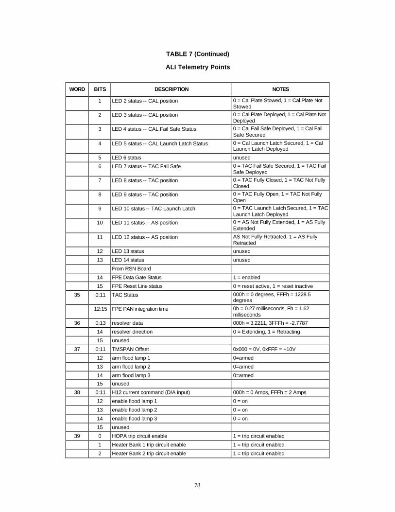
78
TABLE 7 (Continued)
ALI Telemetry Points
WORD BITS DESCRIPTION NOTES
1 LED 2 status -- CAL position 0 = Cal Plate Stowed, 1 = Cal Plate Not Stowed
2 LED 3 status -- CAL position 0 = Cal Plate Deployed, 1 = Cal Plate Not Deployed
3 LED 4 status -- CAL Fail Safe Status 0 = Cal Fail Safe Deployed, 1 = Cal Fail Safe Secured
4 LED 5 status -- CAL Launch Latch Status 0 = Cal Launch Latch Secured, 1 = Cal Launch Latch Deployed
5 LED 6 status unused
6 LED 7 status -- TAC Fail Safe 0 = TAC Fail Safe Secured, 1 = TAC Fail Safe Deployed
7 LED 8 status -- TAC position 0 = TAC Fully Closed, 1 = TAC Not Fully Closed
8 LED 9 status -- TAC position 0 = TAC Fully Open, 1 = TAC Not Fully Open
9 LED 10 status -- TAC Launch Latch 0 = TAC Launch Latch Secured, 1 = TAC Launch Latch Deployed
10 LED 11 status -- AS position 0 = AS Not Fully Extended, 1 = AS Fully Extended
11 LED 12 status -- AS position AS Not Fully Retracted, 1 = AS Fully Retracted
12 LED 13 status unused
13 LED 14 status unused
From RSN Board
14 FPE Data Gate Status 1 = enabled
15 FPE Reset Line status 0 = reset active, 1 = reset inactive
35 0:11 TAC Status 000h = 0 degrees, FFFh = 1228.5 degrees
12:15 FPE PAN integration time 0h = 0.27 milliseconds, Fh = 1.62 milliseconds
36 0:13 resolver data 000h = 3.2211, 3FFFh = -2.7787
14 resolver direction 0 = Extending, 1 = Retracting
15 unused
37 0:11 TMSPAN Offset 0x000 = 0V, 0xFFF = +10V
12 arm flood lamp 1 0=armed
13 arm flood lamp 2 0=armed
14 arm flood lamp 3 0=armed
15 unused
38 0:11 H12 current command (D/A input) 000h = 0 Amps, FFFh = 2 Amps
12 enable flood lamp 1 0 = on
13 enable flood lamp 2 0 = on
14 enable flood lamp 3 0 = on
15 unused
39 0 HOPA trip circuit enable 1 = trip circuit enabled
1 Heater Bank 1 trip circuit enable 1 = trip circuit enabled
2 Heater Bank 2 trip circuit enable 1 = trip circuit enabled

79
TABLE 7 (Continued)
ALI Telemetry Points
WORD BITS DESCRIPTION NOTES
3 Heater Bank 3 trip circuit enable 1 = trip circuit enabled
4 Heater Bank 4 trip circuit enable 1 = trip circuit enabled
5 Motor power trip circuit enable 1 = trip circuit enabled
6 FPE operational power trip circuit enable 1 = trip circuit enabled
7 FPE thermal power trip circuit enable 1 = trip circuit enabled
8 HOPA power status 1=enabled
9 HOPA A status (CAL Launch Latch) 1=HOPA energized
10 HOPA B status (CAL Fail Safe) 1=HOPA energized
11 HOPA C status (TAC Launch Latch - A) 1=HOPA energized
12 HOPA D status (TAC Launch Latch - B) 1=HOPA energized
13 HOPA E status (TAC Fail Safe - A) 1=HOPA energized
14 HOPA F status (TAC Fail Safe - B) 1=HOPA energized
15 Motor power status 1=enabled
40 0 Heater 1 status 1=on
1 Heater 2 status 1=on
2 Heater 3 status 1=on
3 Heater 4 status 1=on
4 Heater 5 status 1=on
5 Heater 6 status 1=on
6 Heater 7 status 1=on
7 Heater 8 status 1=on
8 Heater 9 status 1=on
9 Heater 10 status 1=on
10 Heater 11 status 1=on
11 Heater Bank 1 status 1=on
12 Heater Bank 2 status 1=on
13 Heater Bank 3 status 1=on
14 Heater Bank 4 status 1=on
15 unused
41 0 HOPA trip circuit status 0 = tripped
1 Heater Bank 1 trip circuit status 0 = tripped
2 Heater Bank 2 trip circuit status 0 = tripped
3 Heater Bank 3 trip circuit status 0 = tripped
4 Heater Bank 4 trip circuit status 0 = tripped
5 Motor power trip circuit status 0 = tripped
6 FPE trip circuit 1 status 0 = tripped
7 FPE trip circuit 2 status 0 = tripped
8 FPE operational power status-A 1 = enabled
9 FPE operational power status-B 1 = enabled
10 FPE thermal power status-A 1 = enabled
11 FPE thermal power status-B 1 = enabled
12 FPE MFPA side A plus offset 1 = enabled
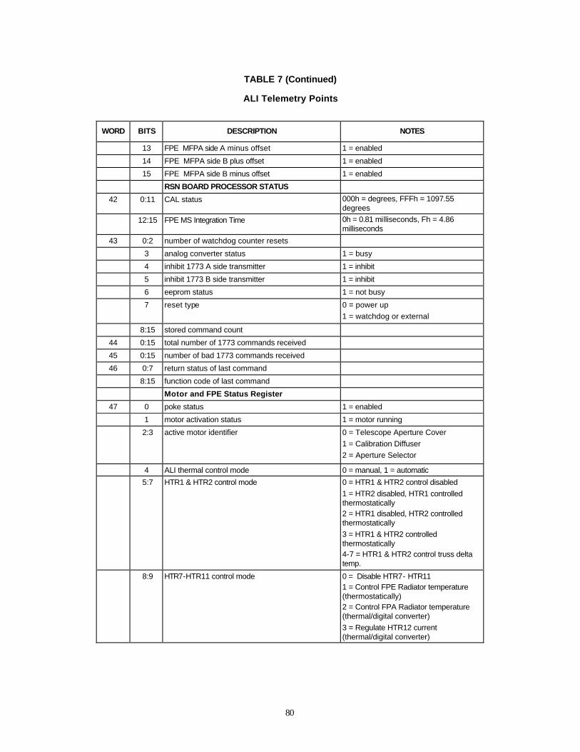
80
TABLE 7 (Continued)
ALI Telemetry Points
WORD BITS DESCRIPTION NOTES
13 FPE MFPA side A minus offset 1 = enabled
14 FPE MFPA side B plus offset 1 = enabled
15 FPE MFPA side B minus offset 1 = enabled
RSN BOARD PROCESSOR STATUS
42 0:11 CAL status 000h = degrees, FFFh = 1097.55 degrees
12:15 FPE MS Integration Time 0h = 0.81 milliseconds, Fh = 4.86 milliseconds
43 0:2 number of watchdog counter resets
3 analog converter status 1 = busy
4 inhibit 1773 A side transmitter 1 = inhibit
5 inhibit 1773 B side transmitter 1 = inhibit
6 eeprom status 1 = not busy
7 reset type 0 = power up
1 = watchdog or external
8:15 stored command count
44 0:15 total number of 1773 commands received
45 0:15 number of bad 1773 commands received
46 0:7 return status of last command
8:15 function code of last command
Motor and FPE Status Register
47 0 poke status 1 = enabled
1 motor activation status 1 = motor running
2:3 active motor identifier 0 = Telescope Aperture Cover
1 = Calibration Diffuser
2 = Aperture Selector
4 ALI thermal control mode 0 = manual, 1 = automatic
5:7 HTR1 & HTR2 control mode 0 = HTR1 & HTR2 control disabled
1 = HTR2 disabled, HTR1 controlled thermostatically 2 = HTR1 disabled, HTR2 controlled thermostatically
3 = HTR1 & HTR2 controlled thermostatically 4-7 = HTR1 & HTR2 control truss delta temp.
8:9 HTR7-HTR11 control mode 0 = Disable HTR7- HTR11 1 = Control FPE Radiator temperature (thermostatically) 2 = Control FPA Radiator temperature (thermal/digital converter)
3 = Regulate HTR12 current (thermal/digital converter)
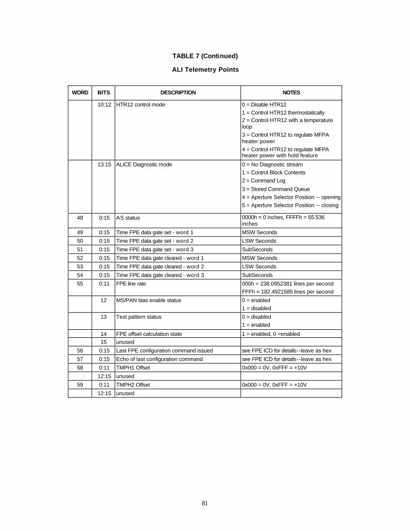
81
TABLE 7 (Continued)
ALI Telemetry Points
WORD BITS DESCRIPTION NOTES
10:12 HTR12 control mode 0 = Disable HTR12
1 = Control HTR12 thermostatically 2 = Control HTR12 with a temperature loop
3 = Control HTR12 to regulate MFPA heater power
4 = Control HTR12 to regulate MFPA heater power with hold feature
13:15 ALICE Diagnostic mode 0 = No Diagnostic stream
1 = Control Block Contents
2 = Command Log
3 = Stored Command Queue
4 = Aperture Selector Position -- opening
5 = Aperture Selector Position -- closing
48 0:15 AS status 0000h = 0 inches, FFFFh = 65.536 inches
49 0:15 Time FPE data gate set - word 1 MSW Seconds
50 0:15 Time FPE data gate set - word 2 LSW Seconds
51 0:15 Time FPE data gate set - word 3 SubSeconds
52 0:15 Time FPE data gate cleared - word 1 MSW Seconds
53 0:15 Time FPE data gate cleared - word 2 LSW Seconds
54 0:15 Time FPE data gate cleared - word 3 SubSeconds
55 0:11 FPE line rate 000h = 238.0952381 lines per second
FFFh = 182.4921585 lines per second
12 MS/PAN bias enable status 0 = enabled
1 = disabled
13 Test pattern status 0 = disabled
1 = enabled
14 FPE offset calculation state 1 = enabled, 0 =enabled
15 unused
56 0:15 Last FPE configuration command issued see FPE ICD for details--leave as hex
57 0:15 Echo of last configuration command see FPE ICD for details--leave as hex
58 0:11 TMPH1 Offset 0x000 = 0V, 0xFFF = +10V
12:15 unused
59 0:11 TMPH2 Offset 0x000 = 0V, 0xFFF = +10V
12:15 unused

82
Figure 46. ASIST I_NOMINAL telemetry page. Several key telemetry points (voltages, currents and temperatures) are listed on this page.

83
Figure 47. ASIST I_HS_STAT telemetry page. This window displays the status of the continuous internal health and safety monitoring performed by the ALICE (see Section 2.8.6).
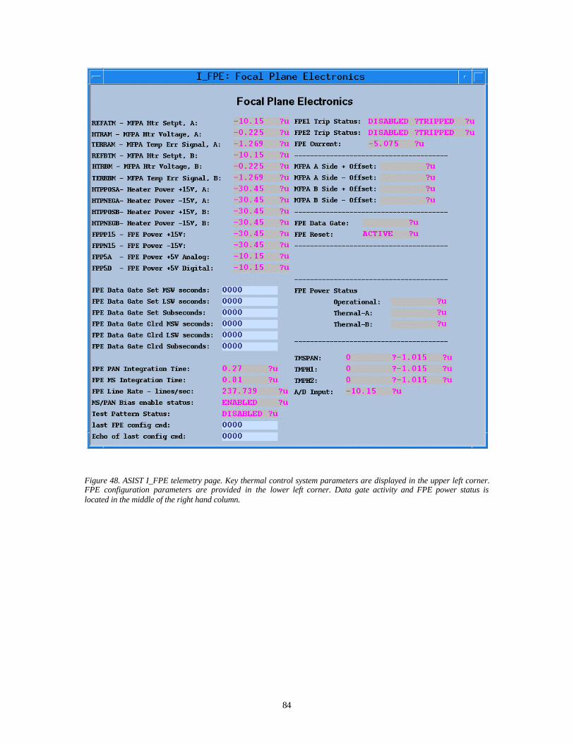
84
Figure 48. ASIST I_FPE telemetry page. Key thermal control system parameters are displayed in the upper left corner. FPE configuration parameters are provided in the lower left corner. Data gate activity and FPE power status is located in the middle of the right hand column.

85
Figure 49. ASIST I_PROCESS_STAT telemetry page. Key parameters include the watchdog reset counter at the top, 1773 summary since last reset in the middle, and thermal control mode status and spacecraft time towards the bottom.

86
Figure 50. ASIST I_TEMPS telemetry page. This page lists all ALI temperature sensor readings. Telescope temperatures are grouped in the upper left, mechanism temperatures are in the lower left, FPE temperatures in the upper right and FPA temperatures in the middle right.
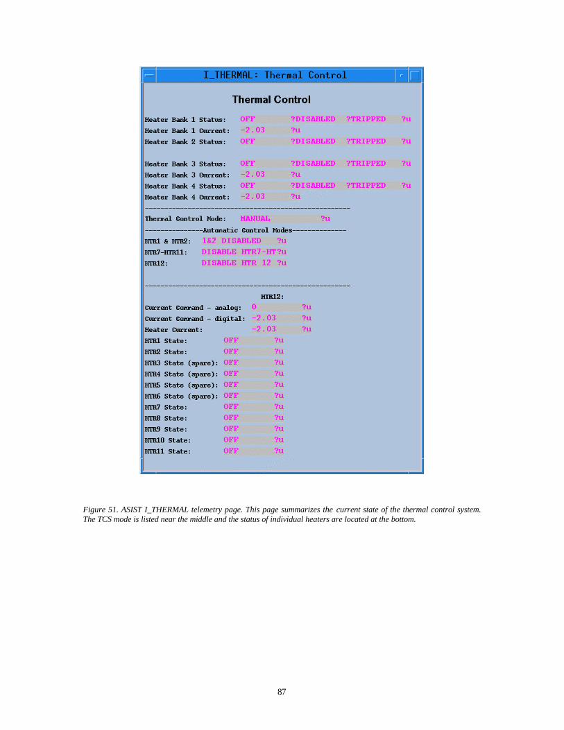
87
Figure 51. ASIST I_THERMAL telemetry page. This page summarizes the current state of the thermal control system. The TCS mode is listed near the middle and the status of individual heaters are located at the bottom.
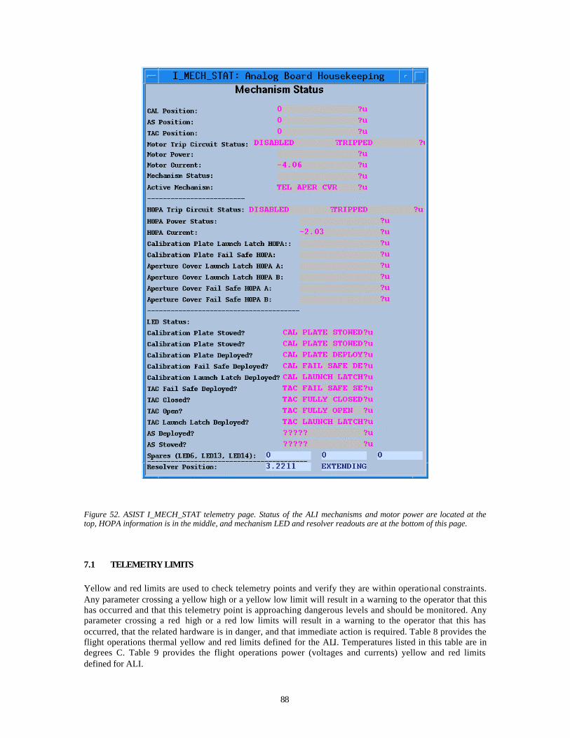
88
Figure 52. ASIST I_MECH_STAT telemetry page. Status of the ALI mechanisms and motor power are located at the top, HOPA information is in the middle, and mechanism LED and resolver readouts are at the bottom of this page.
7.1 TELEMETRY LIMITS
Yellow and red limits are used to check telemetry points and verify they are within operational constraints. Any parameter crossing a yellow high or a yellow low limit will result in a warning to the operator that this has occurred and that this telemetry point is approaching dangerous levels and should be monitored. Any parameter crossing a red high or a red low limits will result in a warning to the operator that this has occurred, that the related hardware is in danger, and that immediate action is required. Table 8 provides the flight operations thermal yellow and red limits defined for the ALI. Temperatures listed in this table are in degrees C. Table 9 provides the flight operations power (voltages and currents) yellow and red limits defined for ALI.
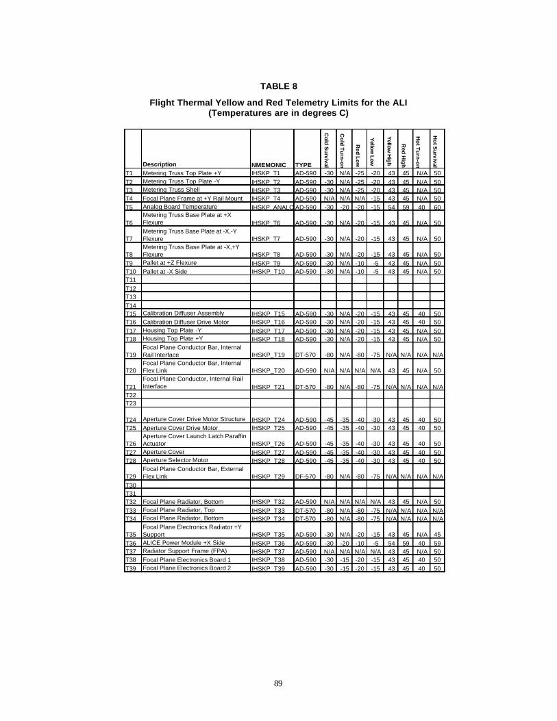
89
TABLE 8
Flight Thermal Yellow and Red Telemetry Limits for the ALI (Temperatures are in degrees C)
Description NMEMONIC TYPE
Co
ld S
urvival
Co
ld T
urn
-on
Red Low
Yellow
Low
Yellow
High
Red
Hig
h
Ho
t Tu
rn-o
n
Ho
t Su
rvival
T1 Metering Truss Top Plate +Y IHSKP_T1 AD-590 -30 N/A -25 -20 43 45 N/A 50
T2 Metering Truss Top Plate -Y IHSKP_T2 AD-590 -30 N/A -25 -20 43 45 N/A 50T3 Metering Truss Shell IHSKP_T3 AD-590 -30 N/A -25 -20 43 45 N/A 50T4 Focal Plane Frame at +Y Rail Mount IHSKP_T4 AD-590 N/A N/A N/A -15 43 45 N/A 50
T5 Analog Board Temperature IHSKP_ANALOGTEMPAD-590 -30 -20 -20 -15 54 59 40 60
T6Metering Truss Base Plate at +X Flexure IHSKP_T6 AD-590 -30 N/A -20 -15 43 45 N/A 50
T7Metering Truss Base Plate at -X,-Y Flexure IHSKP_T7 AD-590 -30 N/A -20 -15 43 45 N/A 50
T8Metering Truss Base Plate at -X,+Y Flexure IHSKP_T8 AD-590 -30 N/A -20 -15 43 45 N/A 50
T9 Pallet at +Z Flexure IHSKP_T9 AD-590 -30 N/A -10 -5 43 45 N/A 50T10 Pallet at -X Side IHSKP_T10 AD-590 -30 N/A -10 -5 43 45 N/A 50T11
T12T13
T14T15 Calibration Diffuser Assembly IHSKP_T15 AD-590 -30 N/A -20 -15 43 45 40 50T16 Calibration Diffuser Drive Motor IHSKP_T16 AD-590 -30 N/A -20 -15 43 45 40 50
T17 Housing Top Plate -Y IHSKP_T17 AD-590 -30 N/A -20 -15 43 45 N/A 50T18 Housing Top Plate +Y IHSKP_T18 AD-590 -30 N/A -20 -15 43 45 N/A 50
T19Focal Plane Conductor Bar, Internal Rail Interface IHSKP_T19 DT-570 -80 N/A -80 -75 N/A N/A N/A N/A
T20Focal Plane Conductor Bar, Internal Flex Link IHSKP_T20 AD-590 N/A N/A N/A N/A 43 45 N/A 50
T21Focal Plane Conductor, Internal Rail Interface IHSKP_T21 DT-570 -80 N/A -80 -75 N/A N/A N/A N/A
T22T23
T24 Aperture Cover Drive Motor Structure IHSKP_T24 AD-590 -45 -35 -40 -30 43 45 40 50T25 Aperture Cover Drive Motor IHSKP_T25 AD-590 -45 -35 -40 -30 43 45 40 50
T26Aperture Cover Launch Latch Paraffin Actuator IHSKP_T26 AD-590 -45 -35 -40 -30 43 45 40 50
T27 Aperture Cover IHSKP_T27 AD-590 -45 -35 -40 -30 43 45 40 50T28 Aperture Selector Motor IHSKP_T28 AD-590 -45 -35 -40 -30 43 45 40 50
T29Focal Plane Conductor Bar, External Flex Link IHSKP_T29 DF-570 -80 N/A -80 -75 N/A N/A N/A N/A
T30T31T32 Focal Plane Radiator, Bottom IHSKP_T32 AD-590 N/A N/A N/A N/A 43 45 N/A 50
T33 Focal Plane Radiator, Top IHSKP_T33 DT-570 -80 N/A -80 -75 N/A N/A N/A N/AT34 Focal Plane Radiator, Bottom IHSKP_T34 DT-570 -80 N/A -80 -75 N/A N/A N/A N/A
T35Focal Plane Electronics Radiator +Y Support IHSKP_T35 AD-590 -30 N/A -20 -15 43 45 N/A 45
T36 ALICE Power Module +X Side IHSKP_T36 AD-590 -30 -20 -10 -5 54 59 40 59T37 Radiator Support Frame (FPA) IHSKP_T37 AD-590 N/A N/A N/A N/A 43 45 N/A 50T38 Focal Plane Electronics Board 1 IHSKP_T38 AD-590 -30 -15 -20 -15 43 45 40 50
T39 Focal Plane Electronics Board 2 IHSKP_T39 AD-590 -30 -15 -20 -15 43 45 40 50
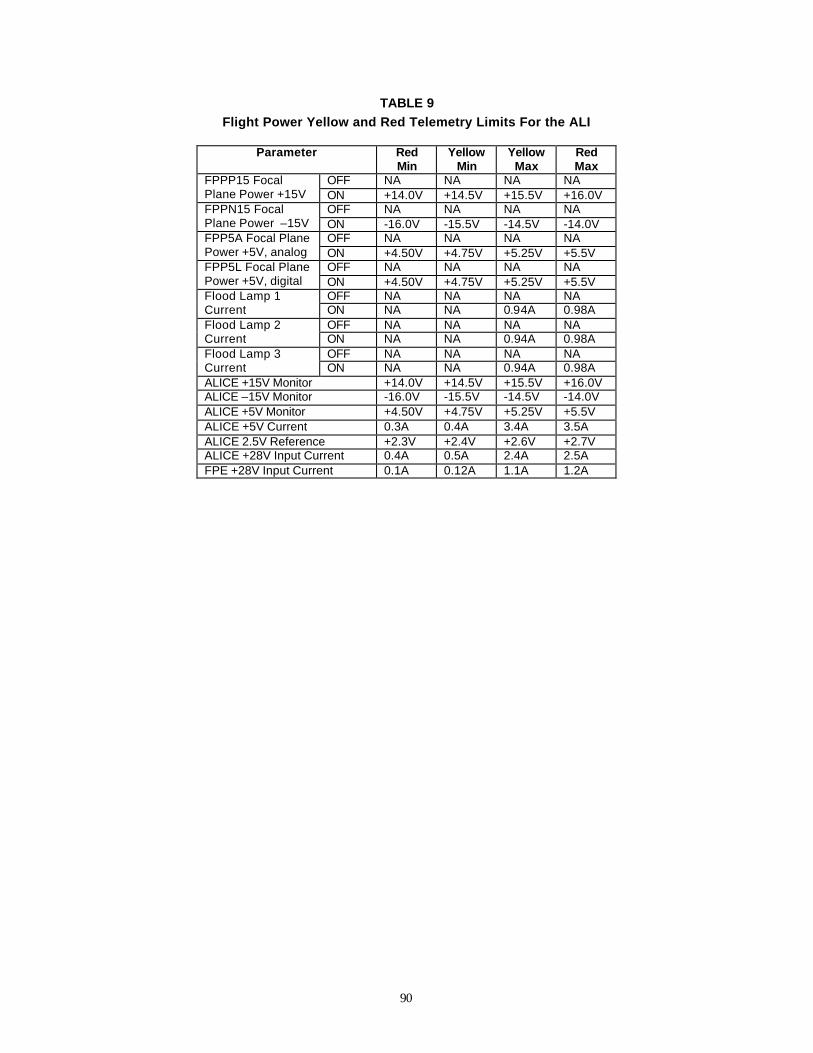
90
TABLE 9 Flight Power Yellow and Red Telemetry Limits For the ALI
Parameter Red
Min Yellow
Min Yellow
Max Red Max
OFF NA NA NA NA FPPP15 Focal Plane Power +15V ON +14.0V +14.5V +15.5V +16.0V
OFF NA NA NA NA FPPN15 Focal Plane Power –15V ON -16.0V -15.5V -14.5V -14.0V
OFF NA NA NA NA FPP5A Focal Plane Power +5V, analog ON +4.50V +4.75V +5.25V +5.5V
OFF NA NA NA NA FPP5L Focal Plane Power +5V, digital ON +4.50V +4.75V +5.25V +5.5V
OFF NA NA NA NA Flood Lamp 1 Current ON NA NA 0.94A 0.98A
OFF NA NA NA NA Flood Lamp 2 Current ON NA NA 0.94A 0.98A
OFF NA NA NA NA Flood Lamp 3 Current ON NA NA 0.94A 0.98A ALICE +15V Monitor +14.0V +14.5V +15.5V +16.0V ALICE –15V Monitor -16.0V -15.5V -14.5V -14.0V ALICE +5V Monitor +4.50V +4.75V +5.25V +5.5V ALICE +5V Current 0.3A 0.4A 3.4A 3.5A ALICE 2.5V Reference +2.3V +2.4V +2.6V +2.7V ALICE +28V Input Current 0.4A 0.5A 2.4A 2.5A FPE +28V Input Current 0.1A 0.12A 1.1A 1.2A
91
8. FLIGHT OPERATIONS The ALI has been designed to require as little commanding as possible. All default parameters are loaded into RAM from a PROM each time the ALICE is powered. Additionally, the thermal control system and health and safety interlocks are fully autonomous. As a result, it is expected that only commanding of the focal plane electronics and mechanisms will be required during flight operations.
8.1 POWER ON AND IDLE MODE
To power on the ALI, the ASIST I_ALI_POWERON Systems Test and Operations Language (STOL) procedure should be executed. This will provide +28 V bus power to the ALICE. The ALICE will configure itself according to the default parameters listed in Table 5. The focal plane operational power will not be active but the A side of the thermal control system will be functional and will autonomously attempt to regulate the focal plane temperature to 220 K and maintain a thermal differential of <8 K between the top and bottom plates of the metering truss by manipulating heaters H1, 2, and 7-12. The ALICE does not check the positions of the ALI mechanisms after being powered. Therefore, it is important to correctly configure the ALI prior to terminating power to the ALICE. It is also recommended that the state of the mechanisms be checked immediately after the ALI is powered.
8.2 ACHIEVING THERMAL EQUILIBRIUM
A review of the thermal control system is provided in Section 2.9. After a period of several orbits the ALI should achieve thermal stability and be ready for data acquisition. If a data collection event is attempted prior to the establishment of thermal equilibrium of the focal plane, Health and Safety Register #14 may indicate an anomaly. This situation poses no health risks to the instrument, has been observed during thermal vacuum testing at Goddard, and is the due to the fact that the ALI is not designed to collect data until the FPA is at a stable temperature.
8.3 RELEASING LAUNCH LATCHES AND FAIL-SAFE HOPAS
To fire any high output paraffin actuators, the following STOL procedures should be run during a real time contact with Goddard Space Flight Center. NOTE: A MIT/Lincoln Laboratory staff member is required be present any time a HOPA is fired. Aperture cover launch latch: /i_armhopa circuit_mask = 4 (8 for redundant latch) ; arm HOPA circuit /i_firehopa circuit_mask = 4 (8 for redundant latch) duration = 0 ; fire HOPA circuit wait until /ihskp_ledstat10 = 1 ; wait until latch deployed /i_resethopa ; reset HOPA circuit /i_flush_stored_cmds ; flush all commands Aperture cover fail-safe: NOTE: The aperture cover fail-safe should only be executed in the event of the aperture cover motor (not the aperture selector or solar diffuser motors) completely fails and cannot be recovered. The fail-safe HOPA can only be fired once and the aperture cover can never be closed again. It is
92
mandatory that a MIT/Lincoln Laboratory staff member be present any time a fail-safe HOPA is fired. /i_armhopa circuit_mask = 16 (32 for redundant latch) ; arm HOPA circuit /i_firehopa circuit_mask = 16 (32 for redundant latch) duration = 0 ; fire HOPA circuit wait until /ihskp_ledstat7 = 1 ; wait until fail-safe deployed /i_resethopa ; reset HOPA circuit /i_flush_stored_cmds ; flush all commands Solar Diffuser Launch Latch: /i_armhopa circuit_mask = 1 ; arm HOPA circuit /i_firehopa circuit_mask = 1 duration = 0 ; fire HOPA circuit wait until /ihskp_ledstat5 = 1 ; wait until latch deployed /i_resethopa ; reset HOPA circuit /i_flush_stored_cmds ; flush all commands Solar Diffuser Fail-safe: NOTE: The solar diffuser fail-safe should only be executed in the event of the solar diffuser motor (not the aperture cover or aperture selector motors) completely fails and cannot be recovered. The fail-safe HOPA can only be fired once and the solar diffuser can never be deployed again. It is mandatory that a MIT/Lincoln Laboratory staff member be present any time a fail-safe HOPA is fired. /i_armhopa circuit_mask = 2 ; arm HOPA circuit /i_firehopa circuit_mask = 2 duration = 0 ; fire HOPA circuit wait until /ihskp_ledstat4 = 0 ; wait until fail-safe deployed /i_resethopa ; reset HOPA circuit /i_flush_stored_cmds ; flush all commands
8.4 DARK DATA COLLECTION
A dark scene will provide valuable data with which the dark current and noise of the focal plane may be investigated. To configure the ALI for dark data collection, the focal plane operational power must be activated, focal plane electronics configured, and the focal plane allowed to stabilize for four minutes. The following sequence is recommended for nominal dark scene data collections: /i_setfpepower power_mask = 5 ; activate focal plane operational power wait 10 ; wait 10 seconds for FPE to come up /i_configfpe config_command = 37583 ; configure FPE /i_configfpe config_command = 16396 ; configure FPE /i_configfpe config_command = 16908 ; configure FPE wait 240 seconds ; allow time for the focal plane to warm-up /i_set_fpe_dg duration = -1 ; activate focal plane data gate wait 30 seconds ; collect dark current /i_clr_fpe_dg ; reset focal plane data gate /i_setfpepower power_mask = 4 ; deactivate focal plane operational power
93
8.5 EARTH SCENE DATA COLLECTION
A standard earth observation requires three primary activities: open the aperture cover, collect data, and close the aperture cover. The following sequence is recommended for nominal earth scene data collection: /i_setfpepower power_mask = 5 ; activate focal plane operational power wait 10 ; wait 10 seconds for FPE to come up /i_configfpe config_command = 37583 ; configure FPE /i_configfpe config_command = 16396 ; configure FPE /i_configfpe config_command = 16908 ; configure FPE wait 240 seconds ; allow time for the focal plane to warm-up /i_mechpower ; enable mechanism power /i_mechactive direction=0 mechanism=0 num_steps=0 ; open the aperture cover wait 30 ; allow time for the aperture cover to open /i_set_fpe_dg duration = -1 ; activate focal plane data gate wait 30 seconds ; collect earth data /i_clr_fpe_dg ; reset focal plane data gate /i_mechpower ; enable mechanism power /i_mechactive direction=1 mechanism=0 num_steps=0 ; close the aperture cover wait 30 ; allow time for the aperture cover to close /i_setfpepower power_mask = 4 ; deactivate focal plane operational power
8.6 INTERNAL LAMP DATA COLLECTION
Internal lamp data will be used on orbit to track the radiometric stability of the focal plane and also contamination build-up on detector filter surfaces. To configure the ALI for internal lamp data collection, the focal plane operational power must be activated, focal plane electronics configured, and the focal plane allowed to stabilize for four minutes. The following sequence is recommended for nominal internal lamp data collection: /i_setfpepower power_mask = 5 ; activate focal plane operational power wait 10 ; wait 10 seconds for FPE to come up /i_configfpe config_command = 37583 ; configure FPE /i_configfpe config_command = 16396 ; configure FPE /i_configfpe config_command = 16908 ; configure FPE wait 240 seconds ; allow time for the focal plane to warm-up /i_fl_cal ; execute flood lamp script wait 20 ; allow time for flood lamp script to execute /i_setfpepower power_mask = 4 ; deactivate focal plane operational power
8.7 TYPICAL DCE COMMAND SEQUENCE
A typical data collection event or DCE will encompass dark current, earth, and flood lamp data collection elements. The dark current will be used to accurately subtract background levels from each earth scene. Dark data will be collected before and after each earth scene to track background drifting and internal lamp data will be used to assess the radiometric stability of the focal plane, relative to previous and future observations. The following sequence is recommended for a nominal data collection event: /i_setfpepower power_mask = 5 ; activate focal plane operational power wait 10 ; wait 10 seconds for FPE to come up /i_configfpe config_command = 37583 ; configure FPE /i_configfpe config_command = 16396 ; configure FPE /i_configfpe config_command = 16908 ; configure FPE
94
wait 240 seconds ; allow time for the focal plane to warm-up /i_set_fpe_dg duration = 1 ; collect dark current for 1 second wait 2 ; wait 2 seconds /i_mechpower ; enable mechanism power /i_mechactive direction=0 mechanism=0 num_steps=0 ; open the aperture cover wait 30 ; allow time for the aperture cover to open /i_set_fpe_dg duration = -1 ; activate focal plane data gate wait 30 seconds ; collect earth data /i_clr_fpe_dg ; reset focal plane data gate /i_mechpower ; enable mechanism power /i_mechactive direction=1 mechanism=0 num_steps=0 ; close the aperture cover wait 30 ; allow time for the aperture cover to close /i_set_fpe_dg duration = 1 ; collect dark current for 1 second wait 2 ; wait 2 seconds /i_fl_cal ; execute flood lamp script wait 20 ; allow flood lamp script to execute /i_setfpepower power_mask = 4 ; deactivate focal plane operational power
8.8 SOLAR CALIBRATION
The primary technique that will be used to radiometrically calibrate and monitor the ALI is known as solar calibration (Section 4.2). To achieve this type of calibration, first the aperture cover is closed, the solar diffuser is placed in front of the M2 mirror (see Section 2.4), and the focal plane is activated. The first two steps ensure the safety of the instrument throughout the remaining sequence. The spacecraft is then slewed so that the instrument is pointed at the Sun. After this maneuver is completed the ALI collects data as the aperture selector is first deployed and then stowed. Standard dark current and internal lamp data are also taken at this time. Once the solar calibration is completed, the instrument is slewed away from the Sun and the solar diffuser is stowed. The following sequence is recommended for a nominal solar calibration: Verify the aperture cover is closed. If not, close it. /i_mechpower /i_mechactive direction = 0 mechanism = 1 num_steps = 0 ; deploy solar diffuser /i_setfpepower power_mask = 5 ; activate focal plane operational power wait 10 ; wait 10 seconds for FPE to come up /i_configfpe config_command = 37583 ; configure FPE /i_configfpe config_command = 16396 ; configure FPE /i_configfpe config_command = 16908 ; configure FPE wait 240 seconds ; allow time for the focal plane to warm-up Slew spacecraft to point instrument at the Sun. Wait for pointing to stabilize. /i_set_fpe_dg duration = 1 ; collect dark current for 1 second wait 2 ; wait 2 seconds /i_set_fpe_dg duration = -1 ; activate focal plane data gate /i_mechpower ; enable mechanism power /i_mechactive direction=0 mechanism= 2 num_steps=0 ; deploy aperture selector wait 20 ; allow time for selector to finish /i_mechpower ; enable mechanism power /i_mechactive direction=1 mechanism= 2 num_steps=0 ; stow aperture selector wait 20 ; allow time for selector to finish /i_clr_fpe_dg ; reset focal plane data gate wait 2 ; wait 2 seconds /i_set_fpe_dg duration = 1 ; collect dark current for 1 second wait 2 ; wait 2 seconds /i_fl_cal ; execute flood lamp script wait 20 ; allow flood lamp script to execute
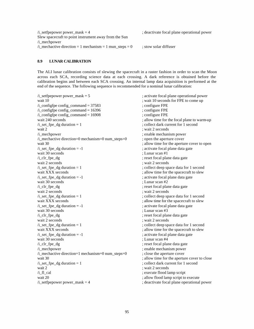
95
/i_setfpepower power_mask = 4 ; deactivate focal plane operational power Slew spacecraft to point instrument away from the Sun /i_mechpower /i_mechactive direction = 1 mechanism = 1 mun_steps = 0 ; stow solar diffuser
8.9 LUNAR CALIBRATION
The ALI lunar calibration consists of slewing the spacecraft in a raster fashion in order to scan the Moon across each SCA, recording science data at each crossing. A dark reference is obtained before the calibration begins and between each SCA crossing. An internal lamp data acquisition is performed at the end of the sequence. The following sequence is recommended for a nominal lunar calibration: /i_setfpepower power_mask = 5 ; activate focal plane operational power wait 10 ; wait 10 seconds for FPE to come up /i_configfpe config_command = 37583 ; configure FPE /i_configfpe config_command = 16396 ; configure FPE /i_configfpe config_command = 16908 ; configure FPE wait 240 seconds ; allow time for the focal plane to warm-up /i_set_fpe_dg duration = 1 ; collect dark current for 1 second wait 2 ; wait 2 seconds /i_mechpower ; enable mechanism power /i_mechactive direction=0 mechanism=0 num_steps=0 ; open the aperture cover wait 30 ; allow time for the aperture cover to open /i_set_fpe_dg duration = -1 ; activate focal plane data gate wait 30 seconds ; Lunar scan #1 /i_clr_fpe_dg ; reset focal plane data gate wait 2 seconds ; wait 2 seconds /i_set_fpe_dg duration = 1 ; collect deep space data for 1 second wait XXX seconds ; allow time for the spacecraft to slew /i_set_fpe_dg duration = -1 ; activate focal plane data gate wait 30 seconds ; Lunar scan #2 /i_clr_fpe_dg ; reset focal plane data gate wait 2 seconds ; wait 2 seconds /i_set_fpe_dg duration = 1 ; collect deep space data for 1 second wait XXX seconds ; allow time for the spacecraft to slew /i_set_fpe_dg duration = -1 ; activate focal plane data gate wait 30 seconds ; Lunar scan #3 /i_clr_fpe_dg ; reset focal plane data gate wait 2 seconds ; wait 2 seconds /i_set_fpe_dg duration = 1 ; collect deep space data for 1 second wait XXX seconds ; allow time for the spacecraft to slew /i_set_fpe_dg duration = -1 ; activate focal plane data gate wait 30 seconds ; Lunar scan #4 /i_clr_fpe_dg ; reset focal plane data gate /i_mechpower ; enable mechanism power /i_mechactive direction=1 mechanism=0 num_steps=0 ; close the aperture cover wait 30 ; allow time for the aperture cover to close /i_set_fpe_dg duration = 1 ; collect dark current for 1 second wait 2 ; wait 2 seconds /i_fl_cal ; execute flood lamp script wait 20 ; allow flood lamp script to execute /i_setfpepower power_mask = 4 ; deactivate focal plane operational power
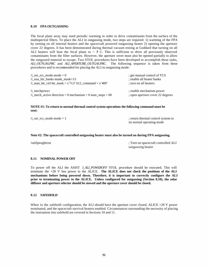
96
8.10 FPA OUTGASSING
The focal plane array may need periodic warming in order to drive contaminants from the surface of the multispectral filters. To place the ALI in outgassing mode, two steps are required: 1) warming of the FPA by turning on all internal heaters and the spacecraft powered outgassing heater 2) opening the aperture cover 22 degrees. It has been demonstrated during thermal vacuum testing at Goddard that turning on all ALI heaters will heat the focal plane to ~ 3° C. This is sufficient to drive all previously observed contaminants from the filter surfaces. However, the aperture cover must also be opened partially to allow the outgassed material to escape. Two STOL procedures have been developed to accomplish these tasks, ALI_OUTGAS.PRC and ALI_APERTURE_OUTGAS.PRC. The following sequence is taken from these procedures and is recommended for placing the ALI in outgassing mode: /i_set_tcs_mode mode = 0 ; get manual control of TCS /i_ena_htr_banks mank_mask=13 ; enable all heater banks /i_man_htr_ctrl htr_mask = x’7c3’ h12_command = x’400’ ; turn on all heaters /i_mechpower ; enable mechanism power /i_mech_active direction = 0 mechanism = 0 num_steps = 60 ; open aperture cover 22 degrees NOTE #1: To return to normal thermal control system operations the following command must be sent: /i_set_tcs_mode mode = 1 ; return thermal control system to
its normal operating mode
Note #2: The spacecraft controlled outgassing heater must also be turned on during FPA outgassing. /talifpeoghtron ; Turn on spacecraft controlled ALI
outgassing heater
8.11 NOMINAL POWER OFF
To power off the ALI the ASIST I_ALI_POWEROFF STOL procedure should be executed. This will terminate the +28 V bus power to the ALICE. The ALICE does not check the positions of the ALI mechanisms before being powered down. Therefore, it is important to correctly configure the ALI prior to terminating power to the ALICE. Unless configured for outgassing (Section 8.10), the solar diffuser and aperture selector should be stowed and the aperture cover should be closed.
8.12 SAFEHOLD
When in the safehold configuration, the ALI should have the aperture cover closed, ALICE +28 V power terminated, and the spacecraft survival heaters enabled. Circumstances surrounding the necessity of placing the instrument into safehold are covered in Sections 10 and 11.
97
9. OPERATIONAL CONSTRAINTS The Advanced Land Imager has three operational constraints:
1. The aperture cover of the instrument must be closed and remain closed if the spacecraft points within 18 degrees of the Sun. This constraint includes periods when the ALI is in the outgassing mode (see Section 8.10). An exception to this constraint is if the spacecraft is on the dark side of the Earth (i.e. looking toward the Sun through the Earth). Care must be used when the spacecraft is leaving eclipse.
2. No high output paraffin actuator (HOPA) may be fired without the consent of an MIT Lincoln
Laboratory cognizant engineer. 3. No solar calibrations may be conducted until after the first 28 days of operation.

98
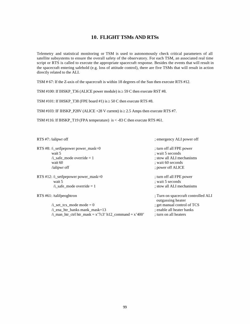
99
10. FLIGHT TSMs AND RTSs Telemetry and statistical monitoring or TSM is used to autonomously check critical parameters of all satellite subsystems to ensure the overall safety of the observatory. For each TSM, an associated real time script or RTS is called to execute the appropriate spacecraft response. Besides the events that will result in the spacecraft entering safehold (e.g. loss of attitude control), there are five TSMs that will result in action directly related to the ALI. TSM # 67: If the Z-axis of the spacecraft is within 18 degrees of the Sun then execute RTS #12. TSM #100: If IHSKP_T36 (ALICE power module) is ≥ 59 C then execute RST #8. TSM #101: If IHSKP_T38 (FPE board #1) is ≥ 50 C then execute RTS #8. TSM #103: IF IHSKP_P28V (ALICE +28 V current) is ≥ 2.5 Amps then execute RTS #7. TSM #116: If IHSKP_T19 (FPA temperature) is < -83 C then execute RTS #61. RTS #7: /ialipwr off ; emergency ALI power off RTS #8: /i_setfpepower power_mask=0 ; turn off all FPE power wait 5 ; wait 5 seconds /i_safe_mode override = 1 ; stow all ALI mechanisms wait 60 ; wait 60 seconds /ialipwr off ; power off ALICE RTS #12: /i_setfpepower power_mask=0 ; turn off all FPE power wait 5 ; wait 5 seconds /i_safe_mode override = 1 ; stow all ALI mechanisms RTS #61: /talifpeoghtron ; Turn on spacecraft controlled ALI
outgassing heater /i_set_tcs_mode mode = 0 ; get manual control of TCS /i_ena_htr_banks mank_mask=13 ; enable all heater banks /i_man_htr_ctrl htr_mask = x’7c3’ h12_command = x’400’ ; turn on all heaters

100
101
11. ALI CONTINGENCIES
Table 10 lists contingency actions to be taken in the event of specific anomalous conditions of the ALI. The following are procedures referenced in this table: Emergency Shutdown of the ALI Terminate +28V power to ALICE immediately
Orderly ALI shutdown: Off FPE Operating and Heater Power (see below) Command ALI to “go to safehold” (I_SAFE_MODE) Power off ALICE
Command to Safehold:
Issue “go to safehold” (I_SAFE_MODE override=1).
On FPE Operating Power:
Issue command to turn on FPE operating power (I_SETFPEPOWER POWER_MASK = 5, FPA heater bus A in operation. I_SETFPEPOWER POWER_MASK = 9, FPA heater bus B in operation.)
Off FPE Operating Power:
Issue command to turn off FPE operating power If Housekeeping word bit 10 = 1 AND bit 11 = 0 THEN issue I_SETFPEPOWER POWER_MASK = 4, (FPA heater bus A in operation). If Housekeeping word bit 10 = 0 AND bit 11 = 1 THEN issue I_SETFPEPOWER POWER_MASK = 8, (FPA heater bus B in operation).
Off FPE Operating and Heater Power
Issue command to turn off FPE operating and heater power (I_SETFPEPOWER POWER_MASK = 0)
On FPA Radiator Outgas Heater
Issue command to turn on FPA radiator outgas heater.
Set Event
Write event message identifying monitor condition.
The table below lists the anomalies identified requiring a timely response, or, at a minimum, the noting of an event. For each potential anomaly, the tables indicate the monitor word and bits in the ALICE telemetry, the limit, if known, the action taken by ALI, and the operational response that should be executed.
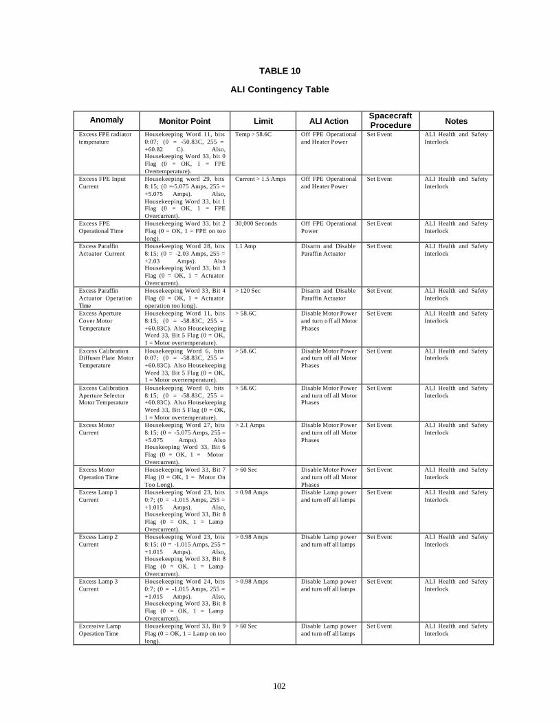
102
TABLE 10
ALI Contingency Table
Anomaly Monitor Point Limit ALI Action Spacecraft Procedure Notes
Excess FPE radiator temperature
Housekeeping Word 11, bits 0:07; (0 = -50.83C, 255 = +60.82 C). Also, Housekeeping Word 33, bit 0 Flag (0 = OK, 1 = FPE Overtemperature).
Temp > 58.6C Off FPE Operational and Heater Power
Set Event ALI Health and Safety Interlock
Excess FPE Input Current
Housekeeping word 29, bits 8:15; (0 =-5.075 Amps, 255 = +5.075 Amps). Also, Housekeeping Word 33, bit 1 Flag (0 = OK, 1 = FPE Overcurrent).
Current > 1.5 Amps
Off FPE Operational and Heater Power
Set Event ALI Health and Safety Interlock
Excess FPE Operational Time
Housekeeping Word 33, bit 2 Flag (0 = OK, 1 = FPE on too long).
30,000 Seconds Off FPE Operational Power
Set Event ALI Health and Safety Interlock
Excess Paraffin Actuator Current
Housekeeping Word 28, bits 8:15; (0 = -2.03 Amps, 255 = +2.03 Amps). Also Housekeeping Word 33, bit 3 Flag (0 = OK, 1 = Actuator Overcurrent).
1.1 Amp Disarm and Disable Paraffin Actuator
Set Event ALI Health and Safety Interlock
Excess Paraffin Actuator Operation Time
Housekeeping Word 33, Bit 4 Flag (0 = OK, 1 = Actuator operation too long).
> 120 Sec Disarm and Disable Paraffin Actuator
Set Event ALI Health and Safety Interlock
Excess Aperture Cover Motor Temperature
Housekeeping Word 11, bits 8:15; (0 = -58.83C, 255 = +60.83C). Also Housekeeping Word 33, Bit 5 Flag (0 = OK, 1 = Motor overtemperature).
> 58.6C Disable Motor Power and turn o ff all Motor Phases
Set Event ALI Health and Safety Interlock
Excess Calibration Diffuser Plate Motor Temperature
Housekeeping Word 6, bits 0:07; (0 = -58.83C, 255 = +60.83C). Also Housekeeping Word 33, Bit 5 Flag (0 = OK, 1 = Motor overtemperature).
> 58.6C Disable Motor Power and turn off all Motor Phases
Set Event ALI Health and Safety Interlock
Excess Calibration Aperture Selector Motor Temperature
Housekeeping Word 0, bits 8:15; (0 = -58.83C, 255 = +60.83C). Also Housekeeping Word 33, Bit 5 Flag (0 = OK, 1 = Motor overtemperature).
> 58.6C Disable Motor Power and turn off all Motor Phases
Set Event ALI Health and Safety Interlock
Excess Motor Current
Housekeeping Word 27, bits 8:15; (0 = -5.075 Amps, 255 = +5.075 Amps). Also Houskeeping Word 33, Bit 6 Flag (0 = OK, 1 = Motor Overcurrent).
> 2.1 Amps Disable Motor Power and turn off all Motor Phases
Set Event ALI Health and Safety Interlock
Excess Motor Operation Time
Housekeeping Word 33, Bit 7 Flag (0 = OK, 1 = Motor On Too Long).
> 60 Sec Disable Motor Power and turn off all Motor Phases
Set Event ALI Health and Safety Interlock
Excess Lamp 1 Current
Housekeeping Word 23, bits 0:7; (0 = -1.015 Amps, 255 = +1.015 Amps). Also, Housekeeping Word 33, Bit 8 Flag (0 = OK, 1 = Lamp Overcurrent).
> 0.98 Amps Disable Lamp power and turn off all lamps
Set Event ALI Health and Safety Interlock
Excess Lamp 2 Current
Housekeeping Word 23, bits 8:15; (0 = -1.015 Amps, 255 = +1.015 Amps). Also, Housekeeping Word 33, Bit 8 Flag (0 = OK, 1 = Lamp Overcurrent).
> 0.98 Amps Disable Lamp power and turn off all lamps
Set Event ALI Health and Safety Interlock
Excess Lamp 3 Current
Housekeeping Word 24, bits 0:7; (0 = -1.015 Amps, 255 = +1.015 Amps). Also, Housekeeping Word 33, Bit 8 Flag (0 = OK, 1 = Lamp Overcurrent).
> 0.98 Amps Disable Lamp power and turn off all lamps
Set Event ALI Health and Safety Interlock
Excessive Lamp Operation Time
Housekeeping Word 33, Bit 9 Flag (0 = OK, 1 = Lamp on too long).
> 60 Sec Disable Lamp power and turn off all lamps
Set Event ALI Health and Safety Interlock

103
TABLE 10 (Continued)
ALI Contingency Table Excessive Heater Bank 1 Current
Housekeeping Word 29, bits 0:7; (0 = -2.03 Amps, 255 = +2.05 Amps). Also, Housekeeping Word 33, Bit 10 Flag (0 = OK, 1 = Heater Bank 1 Overcurrent).
> 1.1 Amp Disable Heater Bank 1 Power
Set Event ALI Health and Safety Interlock
Excessive Heater Bank 3 Current
Housekeeping Word 30, bits 0:7; (0 = -2.03 Amps, 255 = +2.05 Amps). Also, Housekeeping Word 33, Bit 12 Flag (0 = OK, 1 = Heater Bank 3 Overcurrent).
> 1.1 Amp Disable Heater Bank 1 Power
Set Event ALI Health and Safety Interlock
Excessive Heater Bank 4 Current
Housekeeping Word 29, bits 8:15; (0 = -2.03 Amps, 255 = +2.05 Amps). Also, Housekeeping Word 33, Bit 13 Flag (0 = OK, 1 = Heater Bank 4 Overcurrent).
> 1.1 Amp Disable Heater Bank 1 Power
Set Event ALI Health and Safety Interlock
FPE Thermal Control Fault
Housekeeping Word 33, Bit 14 Flag (0 = OK, 1 = FPE Thermal Control Fault).
FPE Operational Power On AND FPA Rail Heater Power >0
Disable FPE Thermal Control Power
Set Event ALI Health and Safety Interlock
High ALICE Power Module Temperature
Housekeeping Word 1, bits 8:15; (0 = -50.83C, 255 = +60.83C)
> 53C None For four (4) consecutive occurrences: Set Event
T36 Warning
Excess ALICE Power Module Temperature
Housekeeping Word 1, bits 8:15; (0 = -50.83C, 255 = +60.83C)
> 58C None For four (4) consecutive occurrences: Orderly ALI Shutdown ; Set Event
High FPE Board 1 Temperature
Housekeeping Word 2, bits 8:15; (0 = -50.83C, 255 = +60.83C)
> 42C None For four (4) consecutive occurrences: Set Event
T38 Warning
Excessive FPE Board 1 Temperature
Housekeeping Word 5, bits 8:15; (0 = -50.83C, 255 = +60.83C)
>44C None For four (4) consecutive occurrences: Off FPE Operating Power; Set Event
High FPE Board 2 Temperature
Housekeeping Word 5, bits 8:15; (0 = -50.83C, 255 = +60.83C)
> 42C None For four (4) consecutive occurrences: Set Event
T39 Warning
Excessive FPE Board 2 Temperature
Housekeeping Word 5, bits 8:15; (0 = -50.83C, 255 = +60.83C)
>44C None For four (4) consecutive occurrences: Off FPE Operating Power; Set Event
Extremely Cold FPA Conductor Bar
Housekeeping Word 13, bits 0:07; (0 = -39.55C, 255 = -100.45C)
< -74C None For four (4) consecutive occurrences: Set Event
T19 Warning
Excessively Cold FPA Conductor Bar
Housekeeping Word 13, bits 0:07; (0 = -39.55C, 255 = -100.45C)
< -79C None For four (4) consecutive occurrences: On FPA Radiator Outgas Heater; Set Event
Extremely Cold FPE Radiator Temperature
Housekeeping Word 11, bits 0:07; (0 = -50.83C, 255 = +60.83C)
<-14C None For four (4) consecutive occurrences: Set Event
T35 Warning
Excessively Cold FPE Radiator Temperature
Housekeeping Word 11, bits 0:07; (0 = -50.83C, 255 = +60.83C)
<-19C None For four (4) consecutive occurrences: On FPE Operational Power, Set Event
Excessive ALICE +28V Current
>2.5 Amps None For four (4) consecutive occurrences: Emergency shutdown of the ALI, Set Event

104
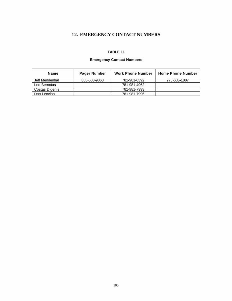
105
12. EMERGENCY CONTACT NUMBERS
TABLE 11
Emergency Contact Numbers
Name Pager Number Work Phone Number Home Phone Number
Jeff Mendenhall 888-508-9863 781-981-0392 978-635-1887 Leo Bernotas 781-981-4962 Costas Digenis 781-981-7993 Don Lencioni 781-981-7996

106

107
13. SUMMARY The ALI has demonstrated breakthrough technologies in the large non-cryogenic MS/Pan FPA, Wide FOV telescope, and silicon carbide optics. It has been thoroughly tested, characterized, and calibrated. It is expected with high confidence that flight tests will validate data continuity with Landsat 7. It provides a pathfinder for an attractive follow-on Landsat and, with technology transfer, would significantly lower follow-on costs

108
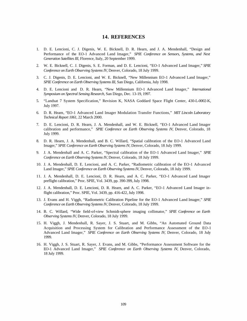
109
14. REFERENCES 1. D. E. Lencioni, C. J. Digenis, W. E. Bicknell, D. R. Hearn, and J. A. Mendenhall, “Design and
Performance of the EO-1 Advanced Land Imager,” SPIE Conference on Sensors, Systems, and Next Generation Satellites III, Florence, Italy, 20 September 1999.
2. W. E. Bicknell, C. J. Digenis, S. E. Forman, and D. E. Lencioni, “EO-1 Advanced Land Imager,” SPIE Conference on Earth Observing Systems IV, Denver, Colorado, 18 July 1999.
3. C. J. Digenis, D. E. Lencioni, and W. E. Bicknell, “New Millennium EO-1 Advanced Land Imager,” SPIE Conference on Earth Observing Systems III, San Diego, California, July 1998.
4. D. E. Lencioni and D. R. Hearn, “New Millennium EO-1 Advanced Land Imager,” International Symposium on Spectral Sensing Research, San Diego, Dec. 13-19, 1997.
5. “Landsat 7 System Specification,” Revision K, NASA Goddard Space Flight Center, 430-L-0002-K, July 1997.
6. D. R. Hearn, “EO-1 Advanced Land Imager Modulation Transfer Functions,” MIT Lincoln Laboratory Technical Report 1061, 22 March 2000.
7. D. E. Lencioni, D. R. Hearn, J. A. Mendenhall, and W. E. Bicknell, “EO-1 Advanced Land Imager calibration and performance,” SPIE Conference on Earth Observing Systems IV, Denver, Colorado, 18 July 1999.
8. D. R. Hearn, J. A. Mendenhall, and B. C. Willard, “Spatial calibration of the EO-1 Advanced Land Imager,” SPIE Conference on Earth Observing Systems IV, Denver, Colorado, 18 July 1999.
9. J. A. Mendenhall and A. C. Parker, “Spectral calibration of the EO-1 Advanced Land Imager,” SPIE Conference on Earth Observing Systems IV, Denver, Colorado, 18 July 1999.
10. J. A. Mendenhall, D. E. Lencioni, and A. C. Parker, “Radiometric calibration of the EO-1 Advanced Land Imager,” SPIE Conference on Earth Observing Systems IV, Denver, Colorado, 18 July 1999.
11. J. A. Mendenhall, D. E. Lencioni, D. R. Hearn, and A. C. Parker, “EO-1 Advanced Land Imager preflight calibration,” Proc. SPIE, Vol. 3439, pp. 390-399, July 1998.
12. J. A. Mendenhall, D. E. Lencioni, D. R. Hearn, and A. C. Parker, “EO-1 Advanced Land Imager in-flight calibration,” Proc. SPIE, Vol. 3439, pp. 416-422, July 1998.
13. J. Evans and H. Viggh, “Radiometric Calibration Pipeline for the EO-1 Advanced Land Imager,” SPIE Conference on Earth Observing Systems IV, Denver, Colorado, 18 July 1999.
14. B. C. Willard, “Wide field-of-view Schmidt-sphere imaging collimator,” SPIE Conference on Earth Observing Systems IV, Denver, Colorado, 18 July 1999.
15. H. Viggh, J. Mendenhall, R. Sayer, J. S. Stuart, and M. Gibbs, “An Automated Ground Data Acquisition and Processing System for Calibration and Performance Assessment of the EO-1 Advanced Land Imager,” SPIE Conference on Earth Observing Systems IV, Denver, Colorado, 18 July 1999.
16. H. Viggh, J. S. Stuart, R. Sayer, J. Evans, and M. Gibbs, “Performance Assessment Software for the EO-1 Advanced Land Imager,” SPIE Conference on Earth Observing Systems IV, Denver, Colorado, 18 July 1999.