earthmover and construction products...
TRANSCRIPT

EARTHMOVER AND CONSTRUCTIONPRODUCTS CATALOG
Number 104, October 2007 ForPromotionalUseOnly


�WHEEL ENGINEERING, INC.
Safety Warning ...........................................................................................................................................4Rim Sizes .......................................................................................................................................................5Difference between old style and new style...................................................................................6Part Number Location .............................................................................................................................8Identification and Terminology ............................................................................................................9Examples of Wheel Offsets ................................................................................................................. 11Wheel Data Sheets ................................................................................................................................. 12HT2000 Series Products ....................................................................................................................... 14Types TG ..................................................................................................................................................... 15Rim Type TGF ........................................................................................................................................... 16Types T, TD ................................................................................................................................................ 18Types T, VA ................................................................................................................................................. 19Types GR, LR “ONE PIECE” RIMS ......................................................................................................... 21Types AG, AGD ........................................................................................................................................ 22Type 4 Piece .............................................................................................................................................. 2�Type 4 Piece Industrial ......................................................................................................................... 24Rim Type Heavy Duty (HD) � Piece .................................................................................................. 25Types STG, STN ........................................................................................................................................ 26Types HTG, HTN, HTM ........................................................................................................................... 29Types HTHG, HTHM ............................................................................................................................... �2Types RTEL, RHTHM ............................................................................................................................... �5Type RW ..................................................................................................................................................... �8Types MRW ............................................................................................................................................... �9Rim Type MFW ......................................................................................................................................... 40Features and Benefits ........................................................................................................................... 4�Type EHD, 2906 ....................................................................................................................................... 44ADVANCED DESIGN ............................................................................................................................... 466�" Rims & Wheels ................................................................................................................................. 48Type 15 DEGREE EARTHMOVER RIMS ............................................................................................. 51Wheel & Rim Components .................................................................................................................. 52SUR-LOC Bead Seat Bands and Side Rings ................................................................................... 58DRIVER KEYS ............................................................................................................................................. 6�O-RINGS ..................................................................................................................................................... 64
TableofContents

4 WHEEL ENGINEERING, INC.
Warning
W a r n i n g
The task of servicing tires and wheels can be extremely dangerous and should be performed by trained personnel only, using the correct tools and following specific procedures. Failure to heed this warning could lead to serious injury or death. We urge that the following is mandatory reading for all those involved in the servicing of tires and wheels.
Department of Labor Occupation Safety and Heath Administration (OSHA) 29 CFR part 1910.177 entitled Servicing of Single piece and Multi-piece Rim Wheels. NOTE: Single piece rims have the rims made out of a single piece of material as shown on page 21 and multi-piece rims have a loose flange or flange and lock ring as shown on page 9 in this catalog.
Wear protective gloves, footwear, safety glasses and head gear when servicing tire and wheel components.
Further references explaining safety procedures can be found in literature published by the Rubber Manufacturer’s Association, Washington D.C., the National Tire Dealers and Retreaders Association, Washington D.C., and the National Wheel and Rim Association, Jacksonville, FL.
OSHA, Washington D.C.
SaFETY FirST!

5WHEEL ENGINEERING, INC.
14.00-20 10.00-2014.00-21, 16.00-21 10.00-2110.00-24, 11.00-24, 12.00-24, 8.00TG-241�.00-24, 14.00-24 8.00TG-2414.00-24 10.00TG-2416.00-24 10.00VA-241�.00-25, 14.00-25 10.00-25T15.50-25 12.00-2516.00-25 11.25-2517.50-25 14.00-2518.00-25 1�.00-2520.50-25 17.00-2521.00-25 15.00-252�.50-25 19.50-2526.50-25 22.00-2529.50-25 25.00-2524.00-29 17.00-2926.50-29 22.00-25�0/65-29 24.00-2929.50-29 25.00-29��.25-29 27.00-2918.00-�� 1�.00-��27.00-�� 22.00-����.50-�� 28.00-���5/65-�� 28.00-���7.50-�� �2.00-��21.00-�5 15.00-�524.00-�5 17.00-�529.50-�5 25.00-�5��.25-�5 27.00-�5�7.25-�5 �1.00-�5��.50-�9 28.00-�9�7.50-�9, 40.5/75-�9, 40/65-�9, �2.00-�941.25/70-�9 �2.00-�945/65-�9 �6.00-�945/65-45 �6.00-45
24.00-49 17.00-4927.00-49 19.50-49�0.00-51 22.00-51��.00-51 24.00-51�6.00-51 26.00-51�7.50-51 �2.00-5150/65-51 40.00-5150.00-51 40.00-5127.00-56.5 20.00-56.5�0.00-56.5 22.00-56.5�7.00-57 27.00-5740.00-57, 46/90 R57 29.00-5748/95-57, 44/80 R57, 50/90 R57 �2.00-5740/80 R57, 50/80 R57 �4.00-5744/95 R57, 52/80-57 �6.00-5749.50-57, 49.5/85-57, 50/80-57, 52/80-57 �6.00-5744/95 R57, 5�.5/85-57, 55.5/80 R57, 55/80-57 44.00-5758/85 R57 47.00-5765/65-57 52.00-5770/70-57 60.00-575�/80 R6� �6.00-6�55/80 R6� 41.00-6�58/80 R6�, 59/80 R6� 44.00-6�
First, find the tire size you will be using. The recommended rim size is then shown opposite your tire size. The tire size determines the rim size and the proper flange height to use. Due to varied loads, speeds, inflations and types of service, consult with your vendor for additional guidance.
Note: Due to changing tire designs produced by the different tire manufacturers, flange heights may deviate away from the established Tire and Rim Association recommendations. When necessary, please consult with the tire manufacturers technical specifications for the proper flange size. Using the wrong flange results in premature tire failure because the tire bead is not being properly supported.
Doyouknowwhatyourrequiredrimsizeis?

6 WHEEL ENGINEERING, INC.
The difference between “old style” and “new style” is the rim back section design.
The top back section is “old style”. The bottom back section is “new style”.
The top design utilizes 2 to 4 pry bar pockets formed into the back section. These pry bar pockets are used by tire service personnel for breaking the tire off the tire bead area during demounting. The problem with this design is if the tire is seized up real tight and the rim is sufficiently fatigued, the pry bar pockets can be broken off.
The bottom design utilizes a continuous pry bar slot which goes �60 degrees around the rim. This slot is used with a hydraulic tool for forcing the flange back and to push a mounted tire off the tire bead area of the rim. The advantage of this design over the old design is that it has more mass than the old style which results in a stronger rim section. In addition tire service personal have a much greater ease of doing tire changes utilizing the hydraulic tool.
As a practice, we try to only stock the new design rims in ��” to 49” sizes. Old design sizes are available by special request. Currently, 25” and 29” are only available in old design styles.
Whatisthedifferencebetween“oldstyle”and“newstyle”?

7WHEEL ENGINEERING, INC.
The task of servicing tires and wheels can be extremely dangerous and should be performed by trained personnel only, using the correct tools and following specific procedures. Failure to heed a warning could lead to serious injury or death.
SAFETY ALERT WARNING!This safety alert symbol indicates important safety warnings in this
catalog. When you see this symbol, be alert to the possibility of personal injury or death and carefully read the message that follows.

8 WHEEL ENGINEERING, INC.
MAKE SURE PARTS ARE OF CORRECT SIZE AND TYPE BEFORE ASSEMBLY BY CHECKING THE PART NUMBER ON ALL THE RIM COMPONENTS.
Thelocationofthestampedpartnumberisasfollows:

9WHEEL ENGINEERING, INC.
RimTerminology

10 WHEEL ENGINEERING, INC.
InformationRequired
OperatingConditionsMaximum load, inflation pressure, speed, tire size and ply rating.
DesignDetailsBolt circle diameter, number of holes, hole diameter, hole chamfer information, bore or pilot hole size, disc thickness, disc location (offset), hub drawing.
Allrimtypescoveredonthefollowingpagescanbemadeintowheels.Contactyourvendorforadditionaldetails.

11WHEEL ENGINEERING, INC.
WheelDiscStyles
InsetWheel ZerosetWheel
OutsetWheel
FlatDisc FormedDisc
WheelDiscTypes
ExamplesofWheelOffsets
NOTE: Formed discs can come in several different profiles and thicknesses.

12 WHEEL ENGINEERING, INC.

1�WHEEL ENGINEERING, INC.

14 WHEEL ENGINEERING, INC.
Our HT2000 Series products are available in 5 piece earthmover wheels and rims in sizes from 25” to 6�". The HT2000 product line is specially manufactured to address specific wear problems and extend the life of rims and wheels used in earthmoving and mining. Problems such as:
• rim fret or gualing• fretting of side flanges due to flange movement or rotation• lock ring groove wear• corrosion• cracked circumferential and butt welds
These problems can be the result of any or all of the following causes:
• high loads• high pressure applications• corrosive environments• improper component fitment or using the wrong component• improper tire fitment and tire slippage• undersized or oversized rim bases
Our HT2000 products are offered with extended warranties above and beyond what the original rim manufacturer offers. The HT2000 product line is manufactured utilizing our most heavy duty rims. The rims and components are manufactured to our specifications utilizing High Strength Low Alloy (HSLA) steel. The rims are specially hardened using a specially developed process in the side flange interface area and the lock ring groove to prevent wear from movement of the components on the rim. We also offer our HT2000 products with special corrosion prevention treat-ments under the top coat of paint.
Depending on the size of the rim or wheel, the HT2000 product line incorporates all or many of the following fea-tures:
• Reinforced back section and bead seat bands• Bead seats available with the Sur-Loc safety feature• Machined back section/bead seat to side flange interface areas• Machined O-ring and lock ring grooves• Machined side flanges• Machined 45 degree on bead seat bands• HSLA steel for superior strength to weight ratio• “Radial” side flanges with extra width• Shot peened lock ring grooves and back sections• Re-designed circumferential weld joints to assure 100% full weld penetration• Longer weld bridges for more support• Extra thick center bands• Low stress attachment disk designs• Specially designed seamless rolled and forged ring gutter, back, and center disk sections• X-ray or ultrasonic quality assurance of all circumferential welds• Butt welds and circumferential welds made utilizing state of the art computer controlled weld controllers and
monitors• Rims and components manufactured to ISO 9001 quality standards• Extended warranties and guaranteed cost per hour warranties• Certificates of Quality Assurance with wheel or rim serial numbers assigned• Special wheel and rim safety inspection and repair warranty options
The HT2000 series wheels and rims are engineered and produced to provide the customer with the optimal perfor-mance and safety. These products are competitively priced to provide the customer with the best wheel or rim value for their money. Ask your sales person about the HT2000 products for your special application.
HT2000SeriesProducts

15WHEEL ENGINEERING, INC.
RimTypeTG
*PARTNUMBERDESIGNATIONS
TG - identifies a Tubeless Grader rim design for use with only grader tires.DemountablerimsareidentifiedwithaDintherimbasepartnumber.Various valve hole options are available, including tapped holes.Sur-Loc Side Rings are available upon request. See page 58 for Sur-Loc part numbers.Rims and components are manufactured according to ISO 9001 quality standards.
RIMSIZEDIA.-WIDTH/FLANGEHT.
RECOMMENDEDTIRESIZE(S)
PARTNUMBERS ASS’YWEIGHT
LBS.RIMBASE* SIDERING LOCKRING O-RING
24-8.00 / 1.4 10.00-24TG B8024TG F8024TG LR8024TG OR224TG 81.6
12.00-24TG
1�.00-24TG (14 PR MAX.)
14.00-24TG (14 PR MAX.)
24-8.00 / 1.4 10.00-24TG B8024TGD F8024TG LR8024TG OR224TG 81.6
12.00-24TG
1�.00-24TG (14 PR MAX.)
14.00-24TG (14 PR MAX.)
24-10.00 / 1.7 1�.00-24TG B1024TG F1024TG LR1024TG OR224TG 141.4
14.00-24TG
16.00-24TG
24-10.00 / 1.7 1�.00-24TG B1024TGD F1024TG LR1024TG OR224TG 141.4
14.00-24TG
16.00-24TG
TYPETG
TYPETG

16 WHEEL ENGINEERING, INC.
RimTypeTGF
*PARTNUMBERDESIGNATIONS
TG - identifies a Tubeless Grader rim design for use with only grader tires.DemountablerimsareidentifiedwithaDintherimbasepartnumber.Add “F” to Part Number for flatbase rim.Various valve hole options are available, including tapped holes.Sur-Loc Side Rings are available upon request. See page 58 for Sur-Loc part numbers.Rims and components are manufactured according to ISO 9001 quality standards.
RIMSIZEDIA.-WIDTH/FLANGEHT.
RECOMMENDEDTIRESIZE(S)
PARTNUMBERS ASS’YWEIGHT
LBS.RIMBASE* SIDERING LOCKRING O-RING
24-10.00 / 1.7 1�.00-24TG B1024TGF F1024TG LR1024TG OR224TG 141.6
14.00-24TG
16.00-24TG

17WHEEL ENGINEERING, INC.
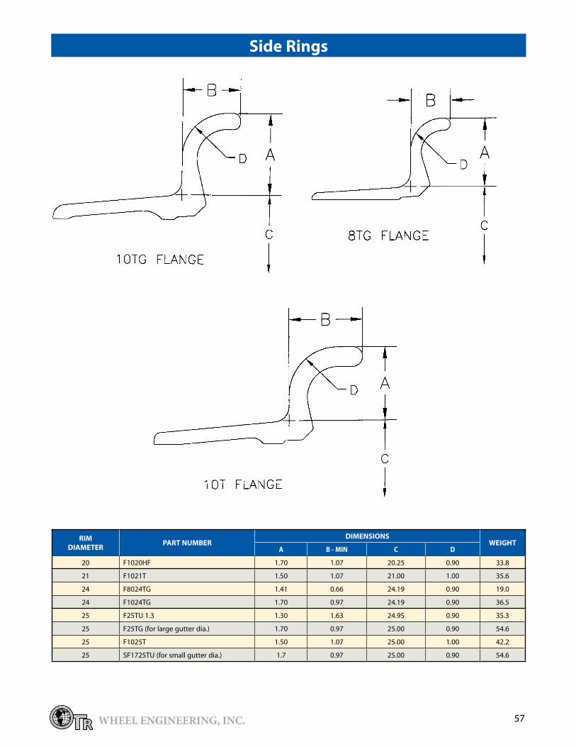
SideRings
RIMDIAMETER PARTNUMBER
DIMENSIONSWEIGHT
A B-MIN C D
24 FB024TG 1.41 0.66 24.19 0.90 19.0
24 F1024TG 1.70 0.97 24.19 0.90 �6.5
RIMDIAMETER
PARTNUMBERCROSSREFERENCE DIMENSIONSWEIGHT
CURRENT REPLACES A B C
24 LR8024G 5��0475-02 2�.4 0.22 0.6� 5.�4
24 LR1024G 5��0484-02 22.9 0.22 0.6� 5.25
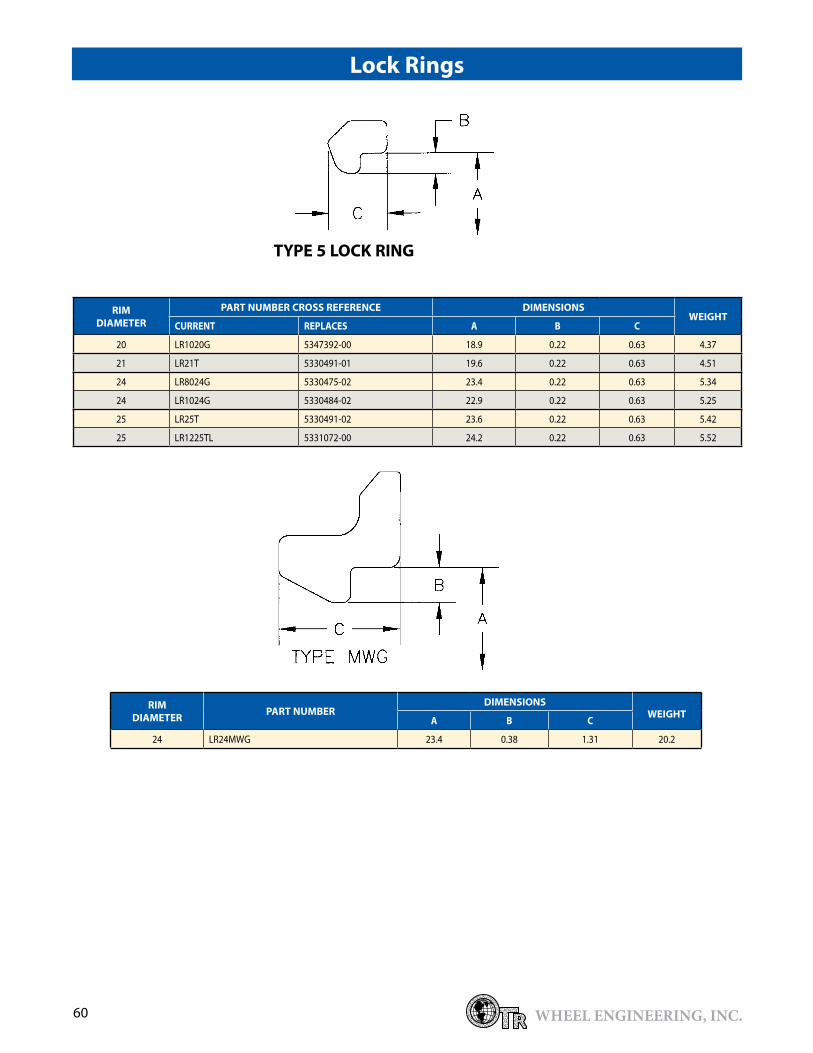
LockRings

18 WHEEL ENGINEERING, INC.
*PARTNUMBERDESIGNATIONS**STANDARDDUTY***Note:F25TGandSF1725TUareNOTinterchangeable.
“D”inthepartnumberdenotesademountablerimbaseAbove rim bases are available with various valve hole options.Sur-Loc Side Rings are available upon request. See page 58 for Sur-Loc part numbers. Rims and components are manufactured according to ISO 9001 quality standards.NHS - Not for Highway Service.
RIMSIZEDIA.-WIDTH/FLANGEHT.
RECOMMENDEDTIRESIZE(S)
PARTNUMBERS ASS’YWEIGHT
LBS.RIMBASE* SIDERING LOCKRING O-RING
20-10.00 / 1.7 (HF) 14.00-20 NHS B1020HF F1020HF LR1020G OR220TG 119.4
21-10.00 / 1.5 14.00-21 NHS B1021T F1021T LR21T OR21T 125.2
16.00-21 NHS
21-18.00 / 1.5 24.00-21 B18021T F1021T LR21T OR21T 170.0
25-10.00 / 1.5 14.00-25 NHS B1025T F1025T LR25T OR25T 149.2
B1025TD F1025T LR25T OR25T
25-12.00 / 1.� 15.5-25 B12025T F25TU1.� LR25T OR25T 1�5.8
15.5-25 (75 PSI MAX.) 51-49055-01** F25TU1.� LR25T OR25T 101.0
25-14.00 / 1.5 17.5-25 B14025T F1025T LR25T OR25T 175.9
17.5-25 (75 PSI MAX.) 51-489��-01** F1025T LR25T OR25T 126.0
25-17.00 / 1.7 (AL) Large Gutter 20.5-25 (16 PR MAX.) B17025TGF F25TG*** LR25T OR25T 188.2
20.5R25 (ONE STAR MAX.) B17025TGF F25TG*** LR25T OR25T 188.2
20.5-25 (75 PSI MAX.) 51-49050-01** F25TG LR25T OR25T 1�5.0
25-17.00 / 1.7 (VL) Small Gutter 20.5-25 (75 PSI MAX.) 51-489�7-01** SF1725TU*** LR25T OR25T 1�5.0
RimTypesT,TD
RIMSIZEDIA.-WIDTH/FLANGEHT.
DIMENSIONS
A B C D E F G H
20-10.00 / 1.7 (HF) 10.00 20.25 1.70 18.642 6.0�1 2.0�1 17.750 0.719
21-10.00 / 1.5 10.00 21.00 1.50 19.�92 6.0�1 2.0�1 18.500 0.719
21-18.00 / 1.5 18.00 21.00 1.50 19.�92 10.0�1 2.0�1 18.500 0.719
25-10.00 / 1.5 10.00 25.00 1.50 2�.�92 6.0�1 2.0�1 22.500 0.719
25-12.00 / 1.� 12.00 25.00 1.�0 2�.�92 6.890 1.898 22.500 0.719
25-14.00 / 1.5 14.00 25.00 1.50 2�.�92 8.0�1 2.0�1 22.500 0.719
25-17.00 / 1.7 (AL) 17.00 25.00 1.70 2�.�92 9.5�1 2.0�1 22.500 0.719
25-17.00 / 1.7 (VL) 17.00 25.00 1.70 2�.�00 9.5�1 2.0�1 22.425 0.719

19WHEEL ENGINEERING, INC.
RIMSIZEDIA.-WIDTH/FLANGEHT.
DIMENSIONS
A B C D E F G H
20-10.00 / 1.7 (HF) 10.00 20.25 1.70 18.642 6.0�1 2.0�1 17.750 0.719
21-10.00 / 1.5 10.00 21.00 1.50 19.�92 6.0�1 2.0�1 18.500 0.719
21-18.00 / 1.5 18.00 21.00 1.50 19.�92 10.0�1 2.0�1 18.500 0.719
25-10.00 / 1.5 10.00 25.00 1.50 2�.�92 6.0�1 2.0�1 22.500 0.719
25-12.00 / 1.� 12.00 25.00 1.�0 2�.�92 6.890 1.898 22.500 0.719
25-14.00 / 1.5 14.00 25.00 1.50 2�.�92 8.0�1 2.0�1 22.500 0.719
25-17.00 / 1.7 (AL) 17.00 25.00 1.70 2�.�92 9.5�1 2.0�1 22.500 0.719
25-17.00 / 1.7 (VL) 17.00 25.00 1.70 2�.�00 9.5�1 2.0�1 22.425 0.719
Note: O-Ring alternate part number is 524946900-01�
RimTypesT,VA
SIZE COMPLETERIM BASEONLY FLANGE LOCKRING “O”RING
TYPE WIDTH DIA. PARTNO. WT. PARTNO. WT. PARTNO. WT. PARTNO. WT. PARTNO. WT
TG �6.00 �2 514744899 459.7 514744801 406.57 F�2TG 51.1 LR�2G 5.7 OR�2TG 0.196
TG 27.00 �2 �8001262 �61.92 �8001261 �04.9� F�2TG1.1� 51.1 LR�2G 5.7 OR�2TG 0.196
TG �1.00 �2 �8001272 407.10 �8001271 �50.10 F�2TG1.1� 51.1 LR�2G 5.7 OR�2TG 0.196
TG �6.00 �2 515079199 46�.57 515079101 406.57 F�2TG1.1� 51.1 LR�2G 5.7 OR�2TG 0.196
TG 40.00 �2 �8001282 508.74 �8001281 451.74 F�2TG1.1� 51.1 LR�2G 5.7 OR�2TG 0.196
TG 44.00 �2 515052999 55�.9 515052901 496.92 F�2TG1.1� 51.1 LR�2G 5.7 0R�2TG 0.196
WIDTH DIA. A C D(Ref.) K L E(Dia.) F(Dia.) H(Dia.)
�6.00 �2 �6.000 1.700 19.0�1 .750 2.0�1 �2.188 �0.084 29.688
27.00 �2 27.000 1.125 8.25 .750 2.0�1 �2.188 �0.084 29.688
�1.00 �2 �1.000 1.125 8.25 .750 2.0�1 �2.188 �0.084 29.688
�6.00 �2 �6.000 1.125 8.97 .750 2.0�1 �2.188 �0.084 29.688
40.00 �2 40.000 1.125 8.25 .750 2.0�1 �2.188 �0.084 29.688
44.00 �2 44.000 1.125 8.75 .750 2.0�1 �2.188 �0.084 29.688

20 WHEEL ENGINEERING, INC.
* K in the side ring part number denotes knurling.
SideRings
RIMDIAMETER PARTNUMBER
DIMENSIONSWEIGHT
A B-MIN C D
20 F1020HF 1.70 1.07 20.25 0.90 ��.8
21 F1021T 1.50 1.07 21.00 1.00 �5.6
25 F25TU 1.� 1.�0 1.6� 24.95 0.90 �5.�
25 F25TG 1.70 0.97 25.00 0.90 54.6
25 F1025T 1.50 1.07 25.00 1.00 42.2
25 SF1725TU 1.7 0.97 25 0.90 54.6
�2 F�2TG 1.70 0.97 �2.18 0.90 51.1
�2 F�2TG 1.1� 1.125 1.66 �2.18 0.60 51.1
�2 F�2TGK 1.1�* 1.125 1.66 �2.18 0.60 51.1
LockRings
RIMDIAMETER
PARTNUMBERCROSSREFERENCE DIMENSIONSWEIGHT
CURRENT REPLACES A B C
20 LR1020G 5�47�92-00 18.9 0.22 0.6� 4.�7
21 LR21T 5��0491-01 19.6 0.22 0.6� 4.51
25 LR25T 5��0491-02 2�.6 0.22 0.6� 5.42
25 LR1225TL 5��1072-00 24.2 0.22 0.6� 5.52
�2 LR�2G 5�47590-00 �0.9 0.22 0.6� 5.7

21WHEEL ENGINEERING, INC.
Type24x9.00GR
Type25x12.00/13.00/14.00LR
*PARTNUMBERDESIGNATIONSAbove rim bases are available with various valve hole options and locations.Rims and components are manufactured according to ISO 9001 quality standards.
RimTypesGR,LR“ONEPIECE”
RIMSIZEDIA.-WIDTH/FLANGEHT.
RECOMMENDEDTIRESIZE(S)
PARTNUMBER
RIMWEIGHT
LBS.
DIMENSIONS
A B C D
24-9.00GR / 1.5 1�.00-24 TG (12 PR MAX.) TUR1401 89 9.00 24.188 1.500 19.480
1�.00R-24 TG (ONE STAR MAX.)
14.00-24 TG (12 PR MAX.)
14.00R-24 TG (ONE STAR MAX.)
16.00-24 TG (12 PR MAX.)
16.00R-24 TG (ONE STAR MAX.)
25-12.00LR/1.4 15.5-25 (12 PR MAX.) 5�4798400 10� 12.00 25.00 1.406 20.468
15.5R-25 (ONE STAR MAX.)
25-1�.00LR /1.4 15.5-25 (12 PR MAX.) 5�47�6500 106 1�.00 25.00 1.406 20.�75
15.5R-25 (ONE STAR MAX.)
17.5-25 (12 PR MAX.)
17.5R-25 (ONE STAR MAX.)
25x14.00LR/1.4 17.5-25 (12 PR MAX.) 5�4798600 109 14.00 25.00 1.406 20.468
17.5R-25 (ONE STAR MAX.)
0.�54

22 WHEEL ENGINEERING, INC.
Flanges
*PARTNUMBERDESIGNATIONS“D”inthepartnumberdenotesademountablerimbase.This rim offered in tube type application only.
RimTypesAG,AGD
RIMSIZEDIA.-WIDTH/FLANGEHT.
RECOMMENDEDTIRESIZE(S)
PARTNUMBERS ASS’YWEIGHT
LBS.RIMBASE* SIDERING LOCKRING
24-10.00 / 2.01�.00-24 NHS B1024AG L2024 LR24MWG 215.5
14.00-24 NHS (2 REQ’D)
24-10.00 / 2.01�.00-24 NHS B1024AGD L2024 LR24MWG 216.0
14.00-24 NHS (2 REQ’D)
RIMDIAMETER PARTNUMBER
DIMENSIONSWEIGHT
A B-MIN C D E
24 L2024 2.0 1.19 24 1.1� 0.44 26.5
LockRings
RIMDIAMETER PARTNUMBER
DIMENSIONSWEIGHT
A B C
24 LR24MWG 2�.4 0.�8 1.�1 20.2

2�WHEEL ENGINEERING, INC.
RimType4Piece
*PARTNUMBERDESIGNATIONSVarious valve hole options are available, including tapped holes.
RIMSIZEDIA.-WIDTH/FLANGEHT.
RECOMMENDEDTIRESIZE(S)
PARTNUMBERS ASS’YWEIGHT
LBS.RIMBASE* BEADSEAT FLANGE LOCKRING O-RING
20-6.5 8.25-20 01105001 01455007 01405004 01�5500� N/A 61.29 lbs or 27.80 kg
20-8.0 11.00-20 0�105001 0�455005 0�40500� 0��55004 N/A 101.6� lbs or 46.10 kg
20-8.5 12.00-20 04105002 0�455005 04405005 0��55004 N/A 124.12 lbs or 56.� kg
20-9.0 1�.00-20 05105001 0�455005 4140500� 41�55002 N/A 145.7� lbs or 66.1 kg
20-10.0 14.00-20 41105001 0�455005 4140500� 41�55002 N/A 15�.22 lbs or 69.5 kg
24-10.0 14.00-24 42105001 42455005 42405004 77�552�6 N/A 196.0 lbs or 88.9 kg
24-11.25/2.�75 16.00-24 771052�� 74105001 774052�7 77�552�6 N/A 218.26 lbs or 99.0 kg
RIMSIZEDIMENSIONS(mm)
A B C D E F G
20-6.5 165.10 514.40 �5.60 494.60 105.15 476.60 508.00
20-8.0 20�.20 514.40 4�.20 489.40 1�2.20 467.40 508.00
20-8.5 215.90 514.40 45.70 486.00 140.00 464.00 508.00
20-9.0 228.60 514.40 50.80 486.00 152.�0 459.00 508.00
20-10.0 254.00 514.40 50.80 486.00 165.00 459.00 508.00
24-10.0 254.00 616.00 50.80 585.60 166.00 558.60 609.60
24-11.25/2.�75 285.75 616.00 6�.50 586.00 181.4� 559.00 609.60
RIMSIZEDIMENSIONS(mm)
A B C D E F G
20-6.5 6.50 20.25 1.40 19.47 4.14 18.76 20.00
20-8.0 8.00 20.25 1.70 19.27 5.20 18.40 20.00
20-8.5 8.50 20.25 1.80 19.1� 5.51 18.27 20.00
20-9.0 9.00 20.25 2.00 19.1� 6.00 18.07 20.00
20-10.0 10.00 20.25 2.00 19.1� 6.50 18.07 20.00
24-10.0 10.00 24.25 2.00 2�.06 6.54 21.99 24.00
24-11.25/2.�75 11.25 24.25 2.50 2�.07 7.14 22.01 24.00

24 WHEEL ENGINEERING, INC.
*PARTNUMBERDESIGNATIONSVarious valve hole options are available, including tapped holes.
RimType4PieceIndustrial
RIMSIZEDIA.-WIDTH/FLANGEHT.
RECOMMENDEDTIRESIZE(S)
PARTNUMBERS ASSEMBLYWEIGHTRIMBASE* FLANGE LOCKRING O-RING
20-9.00W HD 1�.00-20 19105105 12400641 19�55012 N/A 140.0 lbs or 6�.5 kg
20-10.0W 14.00-20 12100745 12400641 19�55012 N/A 144.62 lbs or 65.6 kg
20-11.25 HD 16.00-20 14105018 14400808 19�55012 N/A 228.18 lbs or 10�.5 kg
24-10.00W 14.00-24 1�100744 1�405012 19�55014 N/A 172.84 lbs or 78.4 kg
RIMSIZEDIMENSIONS(mm)
A B C D E
20-9.00W HD 228.6 508 51.� 147.7 46�.6
20-10.0W 254 508 50.8 159.� 467.1
20-11.25 HD 285.75 508 6�.5 181 457.2
24-10.00W 254 609.6 50.8 159.� 568.7
RIMSIZEDIMENSIONS(Inches)
A B C D E
20-9.00W HD 9.00 20.00 2.02 5.81 18.25
20-10.0W 10.00 20.00 2.00 6.27 18.�9
20-11.25 HD 11.25 20.00 2.50 7.1� 18.00
24-10.00W 10.00 24.00 2.00 6.27 22.�9

25WHEEL ENGINEERING, INC.
RimTypeHD3Piece
RIMSIZEDIA.-WIDTH/FLANGEHT.
RECOMMENDEDTIRESIZE(S)
PARTNUMBERS ASS’YWEIGHT
LBS.RIMBASE FLANGE LOCKRING O-RING
25-19.5/2.5 2�.50-25 ER5200A ELFC0�25/2.5 LR255TM OR�25T �84.0
25-22.00/�.0 26.50-25 ER5�00A ELFC0�25/�.0 LR255TM OR�25T 47�.0
25-25.00/�.5 29.50-25 ER5400A ELFC0�25/�.5 LR255TM OR�25T 5�7.5
RIMSIZEDIA.-WIDTH/FLANGEHT.
DIMENSIONS(mm)
A B C D E F G H
25-19.5/2.5 19.50 25 2.50 2�.�8 11.69 2.0� 21.5 1.06
25-22.00/�.0 22.00 25 �.00 2�.�8 12.94 2.0� 21.5 1.06
25-25.00/�.5 25.00 25 �.50 2�.�8 14.�1 2.0� 21.5 1.06

26 WHEEL ENGINEERING, INC.
RimTypesSTG,STN
*PARTNUMBERDESIGNATIONSSTG - identifies a rim base without a bead seat band to rim base driving arrangement.STN - identifies a rim base with a notched gutter driving arrangement to prevent circumferential movement of the com-ponents.DemountablerimsareidentifiedwithaDintherimbasepartnumber(Ex.STGD,STND).Various valve hole options are available, including tapped holes.Sur-Loc bead seat bands are available upon request. See page 58 for Sur-Loc part numbers.These rims are available in special alloy steel for higher pressure, heavy duty applications.
RIMSIZEDIA.-WIDTH/FLANGEHT.
RECOMMENDEDTIRESIZE(S)
PARTNUMBERS ASS’YWEIGHT
LBS.RIMBASE* BEADSEAT FLANGE LOCKRING O-RING
25-11.25 / 2.0 16.00-25 B1125STG BB25STG S2025 LR255TM OR�25T 294.2
25-11.25 / 2.0 16.00-25 B1125STN BB25STN S2025 LR255TN OR�25T 294.6
25-1�.00 / 2.5 18.00-25 B1�25STG BB25STG S2525 LR255TM OR�25T �5�.1
25-1�.00 / 2.5 18.00-25 B1�25STN BB25STN S2525 LR255TN OR�25T �5�.9
25-15.00 / �.0 21.00-25 B1525STG BB25STG S�025 LR255TM OR�25T 408.1
25-15.00 / �.0 21.00-25 B1525STN BB25STN S�025 LR255TN OR�25T 408.5
RIMSIZEDIA.-WIDTH/FLANGEHT.
DIMENSIONS
A B C D E F G H
25-11.25 / 2.0 11.25 25.00 2.00 22.625 7.�12 �.255 21.500 1.06
25-1�.00 / 2.5 1�.00 25.00 2.50 22.625 8.�12 �.255 21.500 1.06
25-15.00 / �.0 15.00 25.00 �.00 22.625 9.�12 �.255 21.500 1.06

27WHEEL ENGINEERING, INC.
RIMDIAMETER PARTNUMBER
DIMENSIONS DRIVERTYPE WEIGHT
A B C
25 BB25STG 5.0 0.56 25.0 NONE 58.4
25 BB25STN 5.0 0.56 25.0 NOTCH 58.4
25 BB25STM 5.0 0.56 25.0 OUTBOARD 59.�
25 BB25ST�1 5.0 0.56 25.0 OUTBOARD 58.�
TYPESSTN,STG,ST31&STM
RIMDIAMETER PARTNUMBER
DIMENSIONSWEIGHT
A B-MIN C D E
25 S2025 2.0 1.25 25 1.25 0.50 28.1
25 S2525 2.5 1.75 25 1.50 0.6� 44.5
25 S�025 �.0 2.1� 25 1.75 0.6� 56.2
IllustrationofBeadSeatBandDriverPocketTypes
ST31 STM STN
Flanges
BeadSeatBands

28 WHEEL ENGINEERING, INC.
LockRings
5TMLOCKRING
5TNLOCKRING
RIMDIAMETER
PARTNUMBERCROSSREFERENCE DIMENSIONSWEIGHT
CURRENT REPLACES A B C
25 LR255TM 52�5677-50 2�.2 0.�4 0.97 12.2
RIMDIAMETER
PARTNUMBERCROSSREFERENCE DIMENSIONS DRIVERTYPE* WEIGHT
CURRENT REPLACES A B C
25 LR255TN 5��0468-00 2�.2 0.�4 0.97 CRIMPED 1�.0

29WHEEL ENGINEERING, INC.
RimTypesHTG,HTN,HTM
*PARTNUMBERDESIGNATIONSHTG-identifies a rim base without a bead seat band to rim base driving arrangement.HTN-identifies a rim base with a notched gutter driving arrangement to prevent circumferential movement of the com-ponents.HTM-identifies a rim base with an outboard driving arrangement.DemountablerimsareidentifiedwithaDintherimbasepartnumber(EX.HTGD,HTND).Various valve hole options are available, including tapped holes.Sur-Loc bead seat bands are available upon request. See page 58 for Sur-Loc part numbers.These rims are available in special alloy steel for higher pressure, heavy duty applications.
RIMSIZEDIA.-WIDTH/FLANGEHT.
RECOMMENDEDTIRESIZE(S)
PARTNUMBERS ASS’YWEIGHT
LBS.RIMBASE* BEADSEAT FLANGE LOCKRING O-RING
25-17.00 / �.5 24.00-25 B1725HTG BB25HTG S�525 LR255TM OR�25T �80.0
25-17.00 / 2.0 20.5-25 B1725HTN BB25STN S2025 LR255TN OR�25T �80.0
25-17.00 / 2.0 20.5-25 B1725HTM BB25STM S2025 LR255TM OR�25T �81.9
25-19.50 / 2.5 2�.5-25 B1925HTG BB25STG S2525 LR255TM OR�25T 446.7
25-19.50 / 2.5 2�.5-25 B1925HTN BB25STN S2525 LR255TN OR�25T 44�.9
25-19.50 / 2.5 2�.5-25 B1925HTM BB25STM S2525 LR255TM OR�25T 445.8
25-22.00 / �.0 26.5-25 B2225HTG BB25HTG S�025 LR255TM OR�25T 499.0
25-22.00 / �.0 26.5-25 B2225HTN BB25HTN S�025 LR255TN OR�25T 504.7
25-22.00 / �.0 26.5-25 B2225HTM BB25HTM S�025 LR255TM OR�25T 515.9
25-25.00 / �.5 29.5-25 B2525HTG BB25HTG S�525 LR255TM OR�25T 551.4
25-25.00 / �.5 29.5-25 B2525HTN BB25HTN S�525 LR255TN OR�25T 55�.7
25-25.00 / �.5 29.5-25 B2525HTM BB25HTM S�525 LR255TM OR�25T 564.4
RIMSIZEDIA.-WIDTH/FLANGEHT.
DIMENSIONS
A B C D E F G H
25-17.00 / �.5 17.00 25.00 �.50 22.625 10.�12 �.255 21.500 1.06
25-17.00 / 2.0 17.00 25.00 2.00 22.625 10.�12 �.255 21.500 1.06
25-19.50 / 2.5 19.50 25.00 2.50 22.625 11.687 �.255 21.500 1.06
25-19.50 / 2.5 19.50 25.00 2.50 22.625 11.687 �.255 21.500 1.06
25-22.00 / �.0 22.00 25.00 �.00 22.625 12.9�7 �.255 21.500 1.06
25-22.00 / �.0 22.00 25.00 �.00 22.625 12.9�7 �.255 21.500 1.06
25-25.00 / �.5 25.00 25.00 �.50 22.625 14.�12 �.255 21.500 1.06

�0 WHEEL ENGINEERING, INC.
ST31/HT31 HT91
RIMDIAMETER PARTNUMBER
DIMENSIONS DRIVERTYPE* WEIGHT
A B C
25 BB25HTG 6.�1 0.65 25.0 NONE 58.4
25 BB25HTN 6.�1 0.65 25.0 NOTCH 70.1
25 BB25HTM 6.�1 0.65 25.0 OUTBOARD 71.4
25 BB25HT�1 6.�1 0.65 25.0 OUTBOARD 71.4
25 BB25HT91 6.�1 0.65 25.0 OUTBOARD 71.4
Bead Seat band driver pocket styles
TYPESHTN,HTM,HTG&HTL
STM/HTM STN/HTN
IllustrationsofBeadSeatBandDriverPocketTypes

�1WHEEL ENGINEERING, INC.
RIMDIAMETER
PARTNUMBERCROSSREFERENCE DIMENSIONS DRIVERTYPE* WEIGHT
CURRENT REPLACES A B C
25 LR255TN 5��0468-00 2�.2 0.�4 0.97 CRIMPED 1�.0
5TNLOCKRING
RIMDIAMETER PARTNUMBER
DIMENSIONSWEIGHT
A B-MIN C D E
25 S2025 2.0 1.25 25 1.25 0.50 28.1
25 S2525 2.5 1.75 25 1.50 0.6� 44.5
25 S�025 �.0 2.1� 25 1.75 0.6� 56.2
25 S�525 �.5 2.25 25 2.00 0.6� 66.8
5TMLOCKRING
Note: used with STN or HTN bead seat bands.
Flanges
LockRings
RIMDIAMETER
PARTNUMBERCROSSREFERENCE DIMENSIONSWEIGHT
CURRENT REPLACES A B C
25 LR255TM 52�5677-50 2�.2 0.�4 0.97 12.2

�2 WHEEL ENGINEERING, INC.
*PARTNUMBERDESIGNATIONSHTH-identifies a Heavy profile rim base with machined o-ring and lock ring grooves. Rims in haulage service can also
have shot-peened lock ring grooves for maximum fatigue life.L and M identify an outboard driving arrangement which prevents circumferential movement of the components.G indicates the absence of a bead seat to rim base driving arrangement.Various valve hole options, including tapped holes are available.
Sure-Loc bead seat bands are available upon request.These rims are available in special alloy steels for higher pressure, heavy duty applications.
RimTypesHTHG,HTHM
RIMSIZEDIA.-WIDTH/FLANGEHT.
RECOMMENDEDTIRESIZE(S)
PARTNUMBERS ASS’YWEIGHT
LBS.RIMBASE* BEADSEAT FLANGE LOCKRING O-RING
29-17.00 / �.5 24.00-29 B1729HTHM BB29HTM S�529 LR295TM OR�29T 561.7
29-22.00 / �.0 26.5-29 B2229HTHM BB29HTM S�029 LR295TM OR�29T 600.2
29-24.00 / �.0 �0/65-29 B2429HTHM BB29HTM S�029 LR295TM OR�29T 6�6.1
29-24.00 / �.5 26.5-29 B2429HTHM BB29HTM S�529 LR295TM OR�29T 650.�
29-25.00 / �.5 29.5-29 B2529HTHM BB29HTM S�529 LR295TM OR�29T 660.6
RIMSIZEDIA.-WIDTH/FLANGEHT.
DIMENSIONS
A B C D E F G H
29-17.00 / �.5 17.00 29.00 �.50 26.625 10.�12 �.567 24.875 1.�8
29-22.00 / �.0 22.00 29.00 �.00 26.625 12.9�7 �.567 24.875 1.�8
29-24.00 / �.0 24.00 29.00 �.00 26.625 1�.984 �.567 24.875 1.�8
29-24.00 / �.5 24.00 29.00 �.50 26.625 1�.984 �.567 24.875 1.�8
29-25.00 / �.5 25.00 29.00 �.50 26.625 14.�12 �.567 24.875 1.�8

��WHEEL ENGINEERING, INC.
RIMDIAMETER PARTNUMBER
DIMENSIONS DRIVERTYPE* WEIGHT
A B C
29 BB29HTG 6.�1 0.65 29.0 NONE 81.0
29 BB29HTM 6.�1 0.65 29.0 OUTBOARD 82.1
29 BB29HTN 6�1 0.65 29.0 NOTCH 80.0
29 BB29HT�1 6.�1 0.65 29.0 OUTBOARD 82.1
29 BB29HT91 6.�1 0.65 29.0 OUTBOARD 82.1
TYPESHTN,HTM,HTG&HTL
STM/HTM
ST31/HT31 HT91
STN/HTN
IllustrationofBeadSeatBandDriverPocketTypes
BeadSeatBands

�4 WHEEL ENGINEERING, INC.
LockRings
Flanges
5TMLOCKRING
5TNLOCKRING
RIMDIAMETER PARTNUMBER
DIMENSIONSWEIGHT
A B-MIN C D E
29 S�029 �.0 2.1� 29 1.75 0.6� 6�.7
29 S�529 �.5 2.25 29 2.00 0.6� 77.0
RIMDIAMETER
PARTNUMBERCROSSREFERENCE DIMENSIONSWEIGHT
CURRENT REPLACES A B C
29 LR295TM 52�5602-50 27.2 0.�4 0.97 14.2
RIMDIAMETER
PARTNUMBERCROSSREFERENCE DIMENSIONSDRIVERTYPE* WEIGHT
CURRENT REPLACES A B C
29 LR295TN 5��046900 27.2 0.�4 0.97 CRIMPED 15.2

�5WHEEL ENGINEERING, INC.
*PARTNUMBERDESIGNATIONSHTEidentifies the Heavy duty gutter with machined o-ring and lock ring grooves. The lock ring grooves are also shot-
peened to obtain maximum fatigue life.L and M identify an outboard driving arrangement which prevents circumferential movement of the components.Various valve hole options, including tapped holes are available.Sur-Loc bead seat bands are available upon request. See page 58 for Sur-Loc part numbers.Rims and components are manufactured according to ISO 9001 quality standards.
RIMSIZEDIA.-WIDTH/FLANGEHT.
RECOMMENDEDTIRESIZE(S)
PARTNUMBERS ASS’YWEIGHT
LBS.RIMBASE* BEADSEAT FLANGE LOCKRING O-RING
��-22.00 / 4.0 27.00-�� B22��RTEL BB��RTL S40�� LR��5TM OR���T 860.2
��-28.00 / �.5 �5/65-�� B28��RHTHM BB��RTL S�5�� LR��5TM OR���T 885.8
��-28.00 / 4.0 ��.5-�� B28��RHTHM BB��RTL S40�� LR��5TM OR���T 905.6
��-�2.00 / 4.5 �7.5-�� B�2��RTEL BB��RTL S45�� LR��5TM OR���T 995.1
�5-27.00 / �.5 ��.25-�5 B27�5RTEL BB�5RTL S�5�5 LR�55TM OR��5T 869.7
�5-�1.00 / 4.0 �7.25-�5 B�1�5RTEL BB�5RTL S40�5 LR�55TM OR��5T 1018.1
�9-28.00 / 4.0 ��.5-�9 B28�9RTEL BB�9RTL S40�9 LR�95TM OR��9T 1080.�
�9-�2.00 / 4.0 40/65-�9 B�2�9RTEL BB�9RTL S40�9 LR�95TM OR��9T 116�.4
�9-�2.00 / 4.541.25/70-�9 B�2�9RTEL BB�9RTL S45�9 LR�95TM OR��9T 1184.0
�7.5-�9
45-�6.00 / 4.5 45/65-45 B�645RTEL BB45RT91 S4545 LR455TM OR�45T 1442.2
RIMSIZEDIA.-WIDTH/FLANGEHT.
DIMENSIONS
A B C D E F G H
��-22.00 / 4.0 22.00 ��.00 4.50 �0.625 1�.187 N/A 27.9�8 1.84
��-28.00 / �.5 28.00 ��.00 �.50 �0.625 16.187 N/A 27.9�8 1.84
��-28.00 / 4.0 28.00 ��.00 4.00 �0.625 16.187 N/A 27.9�8 1.84
��-�2.00 / 4.5 �2.00 ��.00 4.50 �0.625 18.281 N/A 27.9�8 1.84
�5-27.00 / �.5 27.00 �5.00 �.50 �2.625 15.562 N/A 29.9�8 1.84
�5-�1.00 / 4.0 �1.00 �5.00 4.00 �2.625 17.781 N/A 29.9�8 1.84
�9-28.00 / 4.0 28.00 �9.00 4.00 �6.625 16.187 N/A ��.9�8 1.84
�9-�2.00 / 4.0 �2.00 �9.00 4.00 �6.625 18.281 N/A ��.9�8 1.84
�9-�2.00 / 4.5 �2.00 �9.00 4.50 �6.625 18.281 N/A ��.9�8 1.84
45-�6.00 / 4.5 �6.00 45.00 4.50 42.625 20.281 N/A �9.9�8 1.84
SCRAPERCROSSSECTIONRimTypesRTEL,RHTHM

�6 WHEEL ENGINEERING, INC.
BeadSeatBands
RIMDIAMETER PARTNUMBER
DIMENSIONS DRIVERTYPE* WEIGHT
A B C
�� BB��RTG(N)* 6.94 1.1� ��.0 NONE 110.5
�� BB��RTL 6.94 1.1� ��.0 OUTBOARD 111.8
�5 BB�5RTG 6.94 1.1� �5.0 NONE 118.2
�9 BB�9RTL 6.94 1.1� �9.0 OUTBOARD 1�2.6
45 BB45RTG 6.�1 1.1� 45.0 NONE 140.0
45 BB45RTL** 6.�1 1.1� 45.0 OUTBOARD 142.0
49 BB49RTG 6.94 1.1� 49.0 NONE 165.1
49 BB49RTG(N)* 6.94 1.1� 49.0 NONE 165.1
* (N) identifies a bead seat with notches in the outer lip for hydraulic tool access; necessary when used with 1�.00 wide rim assemblies.**Identifies beat seat with large outboard driver pocket DP49A.
IllustrationofBeadSeatBandDriverPocketType
RTL

�7WHEEL ENGINEERING, INC.
LockRings
RIMDIAMETER PARTNUMBER
DIMENSIONSWEIGHT
A B-MIN C D E
�� S25�� 2.5 1.75 �� 1.50 0.6� 58.0
�� S�5�� �.5 2.25 �� 2.00 0.6� 87.6
�� S40�� 4.0 2.56 �� 2.25 0.75 119.6
�� S45�� 4.5 2.88 �� 2.50 0.75 1�9.4
�5 S�0�5 �.0 2.1� �5 1.75 0.6� 77.4
�5 S�5�5 �.5 2.25 �5 2.00 0.6� 92.8
�5 S40�5 4.0 2.56 �5 2.25 0.75 128.4
�9 S40�9 4.0 2.56 �9 2.25 0.75 144.2
�9 S45�9 4.5 2.88 �9 2.50 0.75 164.8
45 S4545 4.5 2.88 45 2.50 0.75 188.8
45 R4545H 4.5 �.4 45 2.5 1.00 269.0
RIMDIAMETER
PARTNUMBERCROSSREFERENCE DIMENSIONSWEIGHT
CURRENT REPLACES A B C
�� LR��5TM 52�5609-50 �1.2 0.�4 0.97 16.2
�5 LR�55TM 52�5701-50 ��.2 0.�4 0.97 17.2
�9 LR�95TM 52�5696-50 �7.4 0.�4 0.97 19.4
45 LR455TM 5249246-50 4�.2 0.�4 0.97 20.9
5TMLOCKRING
Flanges

�8 WHEEL ENGINEERING, INC.
*PARTNUMBERDESIGNATIONSRWH - identifies a machined gutter with low stress W style lock ring design and the Reinforced back section and bead
seat band. The reinforced back and bead seat also offers a continuous lip for the tire removal tools, eliminating pry bar pockets. The lock ring grooves are also shot-peened to obtain maximum fatigue life.
G-indicates the absence of a bead seat band to rim base driving arrangement.DemountablerimsareidentifiedwithaDintherimbasepartnumber.Various valve hole options are available, including tapped holes.Sur-Loc bead seat bands are available upon request.
RimTypeRW
RIMSIZEDIA.-WIDTH/FLANGEHT.
RECOMMENDEDTIRESIZE(S)
PARTNUMBERS ASS’YWEIGHT
LBS.RIMBASE* BEADSEAT FLANGE LOCKRING O-RING
��-1�.00 / 2.5 18.00-�� B1���RWHGD BB��RTGN S25�� LR��W OR���T 557.2
�5-15.00 / �.0 21.00-�5 B15�5RWHGD BB�5RTG S�0�5 LR�5W OR��5T 669.�
�5-17.00 / �.5 24.00-�5 B17�5RWHGD BB�5RTG S�5�5 LR�5W OR��5T 7�4.5
49-17.00 / �.5 24.00-49 B1749RWHGD BB49RTG H�549A LR49W OR�49T 1099.5
49-19.50 / 4.0 27.00-49 B1949RWHGD BB49RTG R4049EH LR49W OR�49T 1196.2
RIMSIZEDIA.-WIDTH/FLANGEHT.
DIMENSIONS
A B C D E F G H
��-1�.00 / 2.5 1�.00 ��.00 2.50 �0.625 8.09� �.567 28.875 1.�8
�5-15.00 / �.0 15.00 �5.00 �.00 �2.625 9.�12 �.567 �0.875 1.�8
�5-17.00 / �.5 17.00 �5.00 �.50 �2.625 10.�12 �.567 �0.875 1.�8
49-17.00 / �.5 17.00 49.00 �.50 46.625 10.61 �.567 44.875 1.�8
49-19.50 / 4.0 19.50 49.00 4.00 46.625 12.00 �.567 44.875 1.�8

�9WHEEL ENGINEERING, INC.
*PARTNUMBERDESIGNATIONSMRWE-identifies a special Machined gutter with low stress W style lock ring design and the reinforced back section.
The lock ring groove is also shot-peened for maximum fatigue life.G - indicates the absence of a bead seat band to rim base driving arrangement.DemountablerimsareidentifiedwithaDintherimbasepartnumber.Various valve hole options are available, including tapped holes.
RIMSIZEDIA.-WIDTH/FLANGEHT.
RECOMMENDEDTIRESIZE(S)
PARTNUMBERS ASS’YWEIGHT
LBS.RIMBASE* BEADSEAT FLANGE LOCKRING O-RING
�5-15.00 / �.0 21.00-�5 B15�5MRWEGD BB�5RTG S�0�5 LR�5W OR��5T 672.0
�5-17.00 / �.5 24.00-�5 B17�5MRWEGD BB�5RTG S�5�5 LR�5W OR��5T 7�4.0
49-17.00 / �.5 24.00-49 B1749MRWEGD BB49RTG H�549A LR49W OR�49T 1141.5
49-19.50 / 4.0 27.00-49 B1949RWEG BB49RTG R4049EH LR49W OR�49T 1��9.8
49-19.50 / 4.0 27.00-49 B1949MRWEGD BB49RTG R4049EH LR49W OR�49T 1��1.6
RimTypeMRW
RIMSIZEDIA.-WIDTH/FLANGEHT.
DIMENSIONS
A B C D E F G H
�5-15.00 / �.0 15.00 �5.00 �.00 �2.625 9.65 4.125 �0.�12 1.78
�5-17.00 / �.5 17.00 �5.00 �.50 �2.625 10.59 4.125 �0.�12 1.78
49-17.00 / �.5 17.00 49.00 �.50 46.625 10.61 4.125 44.062 1.78
49-19.50 / 4.0 19.50 49.00 4.00 46.625 12.00 4.125 44.062 1.78
49-19.50 / 4.0 (RWEG) 19.50 49.00 4.00 46.625 12.00 N/A 4�.945 1.78

40 WHEEL ENGINEERING, INC.
*PARTNUMBERDESIGNATIONSMFW-identifies a special Machined gutter with low stress W style lock ring design and F stands for fixed integrated
back flange.DemountablerimsareidentifiedwithaDintherimbasepartnumber.Various valve hole options are available, including tapped holes.
RIMSIZEDIA.-WIDTH/FLANGEHT.
RECOMMENDEDTIRESIZE(S)
PARTNUMBERS ASS’YWEIGHT
LBS.RIMBASE* BEADSEAT FLANGE LOCKRING O-RING
49-19.50/4.0 27.00-49 B1949MFWEGD BB49RTG R4049EH LR49W OR�49T 1685.9
RimTypeMFW
RIMSIZEDIA.-WIDTH/FLANGEHT.
DIMENSIONS
A B C D E F G H
49-19.50/4.0(MFW) 19.50 49.00 4.00 46.6� 12.00 4.1� 44.06 1.78

41WHEEL ENGINEERING, INC.
LockRings
** HMS is for Hot Forged Seamless Side Ring.
STANDARD MACHINED
Flanges
RIMDIAMETER PARTNUMBER
DIMENSIONSWEIGHT
A B-MIN C D E
�� S25�� 2.5 1.75 �� 1.50 0.6� 58.0
�� S�5�� �.5 2.25 �� 2.00 0.6� 87.6
�� S40�� 4.0 2.56 �� 2.25 0.75 119.6
�� S45�� 4.5 2.88 �� 2.50 0.75 1�9.4
�5 S�0�5 �.0 2.1� �5 1.75 0.6� 77.4
�5 S�5�5 �.5 2.25 �5 2.00 0.6� 92.8
�5 S40�5 4.0 2.56 �5 2.25 0.75 128.4
�9 S40�9 4.0 2.56 �9 2.25 0.75 144.2
�9 S45�9 4.5 2.88 �9 2.50 0.75 164.8
45 S4545 4.5 2.88 45 2.50 0.75 188.8
49 H�549A �.5 �.50 49 2.00 0.87 174.0
49 H4049A 4.0 �.�1 49 2.25 0.875 220.0
49 R4049EH 4.0 �.�9 49 2.25 1.10 29�.0
49 R4049HMS** 4.0 �.66 49 2.25 0.98 287.0
RIMDIAMETER
PARTNUMBERCROSSREFERENCE DIMENSIONSWEIGHT
CURRENT REPLACES A B C
�� LR��W 5�47642-50 �1.1 0.�8 1.10 19.7
�5 LR�5W 5�475�6-50 ��.1 0.�8 1.10 20.8
49 LR49W 5�475�7-50 47.1 0.�8 1.10 29.8

42 WHEEL ENGINEERING, INC.
* (N) identifies a bead seat with notches in the outer lip for hydraulic tool access; necessary when used with 1�.00 wide rim assemblies.
IllustrationofBeadSeatBandDriverPocketType
RTL
BeadSeatBands
RIMDIAMETER PARTNUMBER
DIMENSIONS DRIVERTYPE* WEIGHT
A B C
�� BB��RTG(N)* 6.94 1.1� ��.0 NONE 110.5
�� BB��RTL 6.94 1.1� ��.0 OUTBOARD 111.8
�5 BB�5RTG 6.94 1.1� �5.0 NONE 118.2
�9 BB�9RTL 6.94 1.1� �9.0 OUTBOARD 1�2.6
49 BB49RTG 6.94 1.1� 49.0 NONE 165.1
49 BB49RTG(N)* 6.94 1.1� 49.0 NONE 165.1

4�WHEEL ENGINEERING, INC.
✔���Use of high-strength low-alloy material in crucial components Assures maximum fatigue life.
✔��Shot-peened lock ring groove and other high stress areas Provides favorable residual compressive stress in critical areas for long life.
✔� Machined lock ring grooves and mating component surfaces Assures proper fitment and even stress distribution for maximum fatigue life and safety.
✔� Machined o-ring grooves Provides positive sealing and air retention.
✔��X-Ray, Ultrasonic inspection or Phase Array examination of circumferential weld joints World class quality assurance of submerged arc welds eliminates potential weld
problems.
✔��State-of-the-art computer monitoring of flash butt welds Assures highest quality and reliability.
✔��Superior corrosion resistance and appearance We offer superior corrosion resistance and appearance due to the use of multiple-
stage washers, surface pre-treatment and final top coat with E-Coat or polyester powder coat.
✔��Use of seamless rolled rings and forgings to fabricate critical sections and components
Rolled rings have no butt welds and are manufactured to provide superior strength and fatigue life.
FEATURESANDBENEFITSOF
51",57"&63”RIMSANDWHEELS

44 WHEEL ENGINEERING, INC.
*PARTNUMBERDESIGNATIONSEHD-Extra Heavy Duty design with the valve hole located on rim centerline. Other valve hole options, including
tapped holes are available.DemountablerimbaseisidentifiedwiththesecondDintherimbasepartnumber.L in the rim base and bead seat part number identifies an outboard driving arrangement which prevents circumferential movement of the components.
RimTypeEHD,2906
RIMSIZEDIA.-WIDTH/FLANGEHT.
RECOMMENDEDTIRESIZE(S)
PARTNUMBERS ASS’YWEIGHT
LBS.RIMBASE* BEADSEAT FLANGE LOCKRING O-RING
51-22.00 / 4.5 �0.00-51 B2251EHD BB51EHD H4551 LR51HD OR451T 1975
51-24.00 / 5.0 ��.00-51 B2451EHD BB51EHD R5051H LR51HD OR451T 2255
51-26.00 / 5.0 �6.00-51 B2651EHD BB51EHD R5051H LR51HD OR451T 2�1�
51-�2.00 / 4.5 �7.5-51 B�251EHD BB51EHD H4551 LR51HD OR451T 2�25
51-40.00 / 4.5 50.00-51 B4051EHD BB51EHD R4551H LR51HD OR451T 2540
50/65-51
57-27.00 / 6.0 �7.00-57 B2757EHD BB57EHD R6057H LR57HD OR457T 2800
57-29.00 / 6.0 40.00-57 B2957EHD BB57EHD R6057H LR57HD OR457T 2940
RIMSIZEDIA.-WIDTH/FLANGEHT.
DIMENSIONS
A B C D E F G H
51-22.00 / 4.5 22.00 51.00 4.50 47.750 14.875 5.860 45.218 1.86
51-24.00 / 5.0 24.00 51.00 5.00 47.750 15.875 5.860 45.218 1.86
51-26.00 / 5.0 26.00 51.00 5.00 47.750 16.875 5.860 45.218 1.86
51-�2.00 / 4.5 �2.00 51.00 4.50 47.750 19.875 5.860 45.218 1.86
51-40.00 / 4.5 40.00 51.00 4.50 47.750 2�.875 5.860 45.218 1.86
57-27.00 / 6.0 27.00 57.00 6.00 5�.750 17.�75 5.860 51.218 1.86
57-29.00 / 6.0 29.00 57.00 6.00 5�.750 18.�75 5.860 51.218 1.86

45WHEEL ENGINEERING, INC.
RIMDIAMETER PARTNUMBER
DIMENSIONSWEIGHT
A B-MIN C D E
51 H4551 4.5 2.88 51 2.50 0.88 245.2
51 S4551HF 4.5 �.16 51 2.25 0.71 271.0
51 R4551HMS 4.5 �.16 51 2.50 0.98 518.0
51 S5051HF 5.0 4.09 51 2.75 1.10 450.0
51 R5051H 5.0 4.00 51 2.75 1.00 �60.0
51 R5051HMS 5.0 5.16 51 2.75 1.26 57�.0
57 R5057HMS 5.0 �.�8 51 2.75 1.20 496.0
57 R5057H 5.0 4.5� 57 2.75 0.98 418.9
57 S5057HF 5.0 5.20 57 2.75 1.10 496.0
57 S6057HF 6.0 5.20 57 2.75 1.10 555.6
57 R6057H 6.0 4.44 57 �.�0 1.00 452.0
57 R6057EH 6.0 5.16 57 2.75 1.26 606.�
57 R6057HMS 6.0 5.16 57 2.75 1.26 617.�
57 R6557HMS 6.5 5.16 57 2.75 1.26 661.4
57 S6557HF 6.5 5.59 57 2.75 1.10 610.7
STANDARD MACHINED
RadialFlanges
TYPE EHD with SUR-LOC
RIMDIAMETER PARTNUMBER
DIMENSIONS DRIVERTYPE*
WEIGHTA B C
51 BB51EHD 8.75 2.�6 51.0 NONE �0�.4
57 BB57EHD 8.75 2.�6 57.0 NONE ��8.0
RIMDIAMETER
PARTNUMBERCROSSREFERENCE DIMENSIONSWEIGHT
CURRENT REPLACES A B C
51 LR51HD 5�47�98-50 48.7 0.55 2.�1 94.6
57 LR57HD 5�47457-50 54.7 0.55 2.�1 105.8

46 WHEEL ENGINEERING, INC.
ADVANCEDDESIGNExtraHeavyDutyRim
*PARTNUMBERDESIGNATIONSThe ADVANCEDDESIGNis similar to Type EHD, but with extra capacity for maximum life in extreme applications.Various valve hole options are available, including tapped holes.Demountablerimsareidentifiedwith-01intherimbasepartnumberandNon-Demountablewith-02intherimbasepartnumber.
RIMSIZEDIA.-WIDTH/FLANGEHT.
RECOMMENDEDTIRESIZE(S)
PARTNUMBERSASS’Y
WEIGHTLBS.RIMBASE* BEADSEAT FLANGE
LOCK
RINGO-RING
51-22.00 / 4.5 �0.00-51 514879201 5148704-50 5�47�96-50 LR51HD OR451T 2�16.0
51-24.00 / 5.0 ��.00-51 514878101 5148704-50 5�48�89-00 LR51HD OR451T 2599.0
51-26.00 / 5.0 �6.00-51 514878201 5148704-50 5�48�89-00 LR51HD OR451T 2646.0
51-40.00 / 4.5 50.00-51 514886401 5148865-00 5�48�89-00 LR51HD OR451T �169.0
50/65-51
57-27.00 / 6.0 �7.00-57 514885201 51487�2-50 5�48�88-50 LR57HD OR457T �167.0
57-29.00 / 6.0 40.00-57 514885501 51487�2-50 5�48�88-50 LR57HD OR457T �204.0
RIMSIZEDIA.-WIDTH/FLANGEHT.
DIMENSIONS
A B C D E F G H
51-22.00 / 4.5 22.00 51.00 4.50 47.750 14.875 5.860 45.218 1.86
51-24.00 / 5.0 24.00 51.00 5.00 47.750 15.875 5.860 45.218 1.86
51-26.00 / 5.0 26.00 51.00 5.00 47.750 16.875 5.860 45.218 1.86
51-�2.00 / 4.5 �2.00 51.00 4.50 47.750 19.875 5.860 45.218 1.86
51-40.00 / 4.5 40.00 51.00 4.50 47.750 2�.875 5.860 45.218 1.86
57-27.00 / 6.0 27.00 57.00 6.00 5�.750 17.�75 5.860 51.218 1.86
57-29.00 / 6.0 29.00 57.00 6.00 5�.750 18.�75 5.860 51.218 1.86

47WHEEL ENGINEERING, INC.
TYPEEHDM
STANDARD MACHINED
PHASE 1 LOCK RING
BeadSeatBands
RIMDIAMETER PARTNUMBER
DIMENSIONS DRIVERTYPE WEIGHT
A B C
51 5148704-50 (BB751EHDM) 9.17 1.�8 51.0 NONE �02.0
57 51487�2-50 (BB757EHDM) 9.17 1.�8 57.0 NONE �41.0
RadialFlanges
RIMDIAMETER PARTNUMBER
DIMENSIONSWEIGHT
A B-MIN C D E
51 H4551 4.5 2.88 51 2.50 0.88 245.2
51 S4551HF 4.5 �.16 51 2.50 0.71 271.0
51 R4551HMS 4.5 �.16 51 2.50 0.98 518.0
51 S5051HF 5.0 4.09 51 2.75 1.10 450.0
51 R5051H 5.0 4.00 51 2.75 1.00 �60.0
51 R5051HMS 5.0 5.16 51 2.75 1.26 57�.0
57 R5057HMS 5.0 �.�8 51 2.75 1.20 417.1
57 R5057H 5.0 4.5� 57 2.75 0.98 418.9
57 S5057HF 5.0 5.20 57 2.75 1.10 496.0
57 R5057 HMS Seamless design 5.0 5.0 57 2.75 1.20
57 S6057HF 6.0 5.20 57 2.75 1.10 555.6
57 R6057H 6.0 4.44 57 �.�0 1.00 452.0
57 R6057HMS 6.0 5.16 57 2.75 1.26 617.�
57 R6557HMS 6.5 5.16 57 2.75 1.26 661.4
57 S6557HF 6.5 5.59 57 2.75 1.10 610.7
57 5�48�8850 (S6057EHM) 6.0 4.68 57 �.�0 1.20 547.�
RIMDIAMETER
PARTNUMBERCROSSREFERENCE DIMENSIONSWEIGHT
CURRENT REPLACES A B C
51 LR51HD 5�47�98-50 48.7 0.55 2.�1 94.6
57 LR57HD 5�47457-50 54.7 0.55 2.�1 105.8

48 WHEEL ENGINEERING, INC.
Our 6�" wheels are made from components machined from HSLA seamless forgings. All sections are fully machined for perfect fitment and then assembled using state-of-the-art sub-arc welding equipment. After assembly, all the circumfer-ential weld joints are thoroughly checked using ultrasonic or X-ray inspection equipment.
63"RimsandWheels
RIMSIZEDIA.-WIDTH/FLANGEHT.
RECOMMENDEDTIRESIZE(S)
PARTNUMBERS ASS’YWEIGHT
LBS.RIMBASE* BEADSEAT FLANGE LOCKRING O-RING
6�-�6.00 5�/80 R6� B�66�ADV 51508�950 R506�HMS LR6�HD OR46�T 4657
6�-41.00 55/80 R6� B416�ADV 51508�950 R506�HMS LR6�HD OR46�T 5110
6�-44.00 58/80 R6� B446�FMBS 51508�950 R506�HMS LR6�HD OR46�T 5675
RIMSIZEDIA.-WIDTH/FLANGEHT.
DIMENSIONS
A B C D E F G H
6�-�6.00 �6.00 6� 5.0 59.0 20.78 7.86 56.�1 2.�1
6�-41.00 41.00 6� 5.0 59.0 25.78 7.86 56.�1 2.�1
6�-44.00 44.00 6� 5.0 59.0 27.28 7.86 56.�1 2.�1

49WHEEL ENGINEERING, INC.
TYPEEHDM
LR6�HD LOCK RING
MACHINED
BeadSeatBands
RIMDIAMETER PARTNUMBER
DIMENSIONS DRIVERTYPE WEIGHT
A B C
6� 51508�950-060 (BB76�EHDM) 9.17 1.�8 6� NONE 502.0
6� BB6�TMT 9.17 1.�8 6� NONE 520.0
TYPEEHDTRIM
DIAMETER PARTNUMBERDIMENSIONS DRIVER
TYPE WEIGHTA B C
6� BB6�EHDT 9.75 2.625 6�.0 NONE 780.0
RadialFlanges
RIMDIAMETER PARTNUMBER
DIMENSIONSWEIGHT
A B-MIN C D E
6� S506�HF 5.0 5.51 6� 2.75 1.�8 670.2
6� R506� HMS 5.0 5.0 6� 2.75 1.2 610.0
6� R506�TMT 5.0 5.16 6� 2.75 1.�8 648.2
RIMDIAMETER
PARTNUMBERCROSSREFERENCE DIMENSIONSWEIGHT
CURRENT REPLACES A B C
6� LR6�HD — 60.7 0.55 2.�1 116

50 WHEEL ENGINEERING, INC.
Specialized equipment is necessary for mounting and demounting tubeless off-the-highway tires on 15° tapered rims. The following images are included to show the three types of machines that are currently available.
MountingandDemountingforTubelessOff-The-Highway15°TaperedRims
Figure 1
Figure 2
Figure �

51WHEEL ENGINEERING, INC.
*PARTNUMBERDESIGNATIONSAbove rim bases are available with various valve hole options and locations.Non-Demountable same as illustration except for elimination of mounting band.
Note: This rim design can be made into any type of wheel. This design takes the place of 51x24,51x26 and 49x17,19.5 piece rims. No components let the tire run cooler and give the ultimate in safety. A tire machine is used to fit the tire to the rim.
RIMSIZEDIA.-WIDTH/FLANGEHT.
RECOMMENDEDTIRESIZE(S) RIMSTYLE PART
NUMBER
ASS’YWEIGHT
LBS.
DIMENSIONS VALVEHOLETYPEA B C D E
56.5-20.0 / 1.25 27-56.5
NON-DEMOUNTABLE 5146�8015 908 20.00 24.81 10.69 9.29 44.875 STD
DEMOUNTABLE 5146�8215 1168 20.00 24.81 10.69 9.29 44.875 STD
DEMOUNTABLE 514652715 1211 20.00 24.81 10.61 9.21 44.06� STD
DEMOUNTABLE 514654215 1211 20.00 24.81 10.61 8.97 44.06� 1/2 NPT
56.5-22.00 / 1.25 �0-56.5
NON-DEMOUNTABLE 5146�7915 951 22.00 26.81 11.69 9.29 44.875 STD
DEMOUNTABLE 5146�8115 1220 22.00 26.81 11.69 9.29 44.875 STD
DEMOUNTABLE 514649715 1220 22.00 26.81 11.69 9.0� 44.875 1/2 NPT
DEMOUNTABLE 514657515 126� 22.00 26.81 12.0� 9.�7 44.06� 1/2 NPT
56.5"dia.DEMOUNTABLE
56.5dia.wheel
Type15DegreeEarthmoverRims

52 WHEEL ENGINEERING, INC.
Wheel and Rim components

5�WHEEL ENGINEERING, INC.
RIMDIAMETER PARTNUMBER
DIMENSIONS DRIVERTYPE WEIGHT
A B C
25 BB25STG 5.0 0.56 25.0 NONE 58.4
25 BB25STN 5.0 0.56 25.0 NOTCH 58.4
25 BB25STM 5.0 0.56 25.0 OUTBOARD 59.�
�� BB��STG 5.0 0.56 ��.0 NONE 77.0
RIMDIAMETER PARTNUMBER
DIMENSIONS DRIVERTYPE* WEIGHT
A B C
25 BB25HTG 6.�1 0.65 25.0 NONE 58.4
25 BB25HTN 6.�1 0.65 25.0 NOTCH 70.1
25 BB25HTM 6.�1 0.65 25.0 OUTBOARD 71.4
29 BB29HTG 6.�1 0.65 29.0 NONE 81.0
29 BB29HTM 6.�1 0.65 29.0 OUTBOARD 82.1
�� BB��HTG 6.�1 0.65 ��.0 NONE 92.8
�� BB��HTM 6.�1 0.65 ��.0 OUTBOARD 94.6
�5 BB��MHTG 6.�1 0.65 �5.0 NONE 91.2
�5 BB�5HTL 6.�1 0.65 �5.0 OUTBOARD 100.2
�9 BB�9HTL 6.�1 0.65 �9.0 OUTBOARD 111.0
45 BB45HT91 6.�1 0.65 45.0 OUTBOARD 128.1
TYPESHTN,HTM,HTG&HTL
TYPESSTN,STG&STM
BeadSeatBands

54 WHEEL ENGINEERING, INC.
* (N) identifies a bead seat with notches in the outer lip for hydraulic tool access; necessary when used with 1�.00 wide rim assemblies.
BeadSeatBands
RIMDIAMETER PARTNUMBER
DIMENSIONS DRIVERTYPE* WEIGHT
A B C
�� BB��RTG(N)* 6.94 1.1� ��.0 NONE 110.5
�� BB��RTL 6.94 1.1� ��.0 OUTBOARD 111.8
�5 BB�5RTG 6.94 1.1� �5.0 NONE 118.2
�9 BB�9RTL 6.94 1.1� �9.0 OUTBOARD 1�2.6
49 BB49RTG 6.94 1.1� 49.0 NONE 165.1
49 BB49RTG(N)* 6.94 1.1� 49.0 NONE 165.1
TYPEEHD
RIMDIAMETER PARTNUMBER
DIMENSIONS DRIVERTYPE WEIGHT
A B C
51 BB51EHD 8.75 2.�6 51.0 NONE �0�.4
57 BB57EHD 8.75 2.�6 57.0 NONE ��8.0
6� BB6�EHDT 9.75 2.625 6�.0 NONE 780.0
TYPESRTG&RTL

55WHEEL ENGINEERING, INC.
RIMDIAMETER PARTNUMBER
DIMENSIONSWEIGHT
A B-MIN C D E
24 L2024 2.0 1.19 24 1.1� 0.44 26.5
25 S1525 1.5 1.15 25 1.1� 0.44 2�.8
25 S2025 2.0 1.25 25 1.25 0.50 28.1
25 S2525 2.5 1.75 25 1.50 0.6� 44.5
25 S�025 �.0 2.1� 25 1.75 0.6� 56.2
25 S�525 �.5 2.25 25 2.00 0.6� 66.8
29 S�029 �.0 2.1� 29 1.75 0.6� 6�.7
29 S�529 �.5 2.25 29 2.00 0.6� 77.9
�� S25�� 2.5 1.75 �� 1.50 0.6� 58.0
�� S�5�� �.5 2.25 �� 2.00 0.6� 87.6
�� S40�� 4.0 2.56 �� 2.25 0.75 119.6
�� S45�� 4.5 2.88 �� 2.50 0.75 1�9.4
�5 S�0�5 �.0 2.1� �5 1.75 0.6� 77.4
�5 S�5�5 �.5 2.25 �5 2.00 0.6� 92.8
�5 S40�5 4.0 2.56 �5 2.25 0.75 128.4
�9 S40�9 4.0 2.56 �9 2.25 0.75 144.2
�9 S45�9 4.5 2.88 �9 2.50 0.75 164.8
45 S4545 4.5 2.88 45 2.50 0.75 188.8
45 S4545HF 4.5 �.00 45 2.25 0.71 185.0
45 R4545EH 4.5 �.50 45 2.25 0.98 278.0
45 R4545HMS 4.5 �.�9 45 2.25 0.98 278.0
Flanges

56 WHEEL ENGINEERING, INC.
RIMDIAMETER PARTNUMBER
DIMENSIONSWEIGHT
A B-MIN C D E
49 H�549A �.5 �.50 49 2.00 0.87 174.0
49 S4049HF 4.0 �.11 49 2.25 0.71 185.0
49 H4049A 4.0 �.�1 49 2.25 0.875 220.0
49 R4049HMS 4.0 �.66 49 2.25 0.98 287.0
49 R4049EH 4.0 �.�9 49 2.25 1.10 29�.0
51 H4551 4.5 2.88 51 2.50 0.88 245.2
51 S4551HF 4.5 �.16 51 2.50 0.71 271.0
51 R4551HMS 4.5 �.16 51 2.50 0.98 518.0
51 S5051HF 5.0 4.09 51 2.75 1.10 450.0
51 R5051H 5.0 4.00 51 2.75 1.00 �60.0
51 R5051HMS 5.0 5.16 51 2.75 1.26 57�.0
57 R5057H 5.0 4.5� 57 2.75 0.98 418.9
57 S5057HF 5.0 5.20 57 2.75 1.10 496.0
57 R5057 HMS Seamless design 5.0 5.0 57 2.75 1.2 577.0
57 S6057HF 6.0 5.20 57 2.75 1.10 555.6
57 R6057H 6.0 4.44 57 �.�0 1.00 452.0
57 R6057EH 6.0 5.16 57 2.75 1.26 606.�
57 R6057HMS 6.0 5.16 57 2.75 1.26 617.�
57 R6557HMS 6.5 5.16 57 2.75 1.26 661.4
57 S6557HF 6.5 5.59 57 2.75 1.10 610.7
6� S506�HF 5.0 5.51 6� 2.75 1.�8 670.2
6� R506� HMS Seamless design 5.0 5.59 6� 2.75 1.26 661.9
6� R506�TMT 5.0 5.16 6� 2.75 1.�8 648.2
Flanges
57WHEEL ENGINEERING, INC.
RIMDIAMETER PARTNUMBER
DIMENSIONSWEIGHT
A B-MIN C D
20 F1020HF 1.70 1.07 20.25 0.90 ��.8
21 F1021T 1.50 1.07 21.00 1.00 �5.6
24 F8024TG 1.41 0.66 24.19 0.90 19.0
24 F1024TG 1.70 0.97 24.19 0.90 �6.5
25 F25TU 1.� 1.�0 1.6� 24.95 0.90 �5.�
25 F25TG (for large gutter dia.) 1.70 0.97 25.00 0.90 54.6
25 F1025T 1.50 1.07 25.00 1.00 42.2
25 SF1725TU (for small gutter dia.) 1.7 0.97 25.00 0.90 54.6
SideRings

58 WHEEL ENGINEERING, INC.
SUR-LOC PART # REPLACES SUR-LOCK PART # REPLACES F1021STX F1021T BB��SHTMX BB��HTM F8024STGX F8024TG BB��SHT�1X BB��HT�1 F1024STGX F1024TG BB�5SHTGX BB�5HTG F25STUX1.� F2STU1.� BB�5SRTGX BB�5RTG F1025STX F1025T BB�5SHTLX BB�5HTL F25STGX F25TG BB�5SMHTGX BB�5MHTG BB25SSTNX BB25STN BB�9SRTLX BB�9RTL BB25SSTGX BB25STG BB�9SRTGX BB�9RTG BB25SHTNX BB25HTN BB�9SHTLX BB�9HTL BB25SHTMX BB25HTM BB45SHT91X BB45HT91 BB25SHTGX BB25HTG BB49SRTGX BB49RTG BB29SHTGX BB29HTG BB51EHD BB51HDT BB��SSTGX BB��STG BB57EHD BB57HDT BB��SRTG(N)X BB��RTG(N)
An extension added to the face of the bead seat band or side ring interferes with a misassembled, mismatched or distorted lock ring preventing contact with the o-ring and thereby prevents inflation.
MISASSEMBLEDLOCKRING
MISMATCHEDLOCKRING
DISTORTEDLOCKRING
SUR-LOCBeadSeatBands&SideRings
FOREXTRAPROTECTIONDURINGINFLATION
PARTNUMBERSANDSUR-LOCPARTNUMBER

59WHEEL ENGINEERING, INC.
BeadSeatBands
TYPEADVANCED
TYPEEHDT
RIMDIAMETER PARTNUMBER
DIMENSIONS DRIVERTYPE WEIGHT
A B C
6� BB6�EHDT 9.75 2.625 6�.0 NONE 780.0
RIMDIAMETER
RIMDIAMETER
DIMENSIONS DRIVERTYPE WEIGHT
A B C
51 5148704-50 (BB751EHDM) 9.17 1.�8 51.0 NONE �02.0
57 51487�2-50 (BB757EHDM) 9.17 1.�8 57.0 NONE �41.0
6� 51508�950-060 9.17 1.�8 6�.0 NONE 502.0
60 WHEEL ENGINEERING, INC.
RIMDIAMETER
PARTNUMBERCROSSREFERENCE DIMENSIONSWEIGHT
CURRENT REPLACES A B C
20 LR1020G 5�47�92-00 18.9 0.22 0.6� 4.�7
21 LR21T 5��0491-01 19.6 0.22 0.6� 4.51
24 LR8024G 5��0475-02 2�.4 0.22 0.6� 5.�4
24 LR1024G 5��0484-02 22.9 0.22 0.6� 5.25
25 LR25T 5��0491-02 2�.6 0.22 0.6� 5.42
25 LR1225TL 5��1072-00 24.2 0.22 0.6� 5.52
TYPE5LOCKRING
LockRings
RIMDIAMETER PARTNUMBER
DIMENSIONSWEIGHT
A B C
24 LR24MWG 2�.4 0.�8 1.�1 20.2

61WHEEL ENGINEERING, INC.
RIMDIAMETER
PARTNUMBERCROSSREFERENCE DIMENSIONSWEIGHT
CURRENT REPLACES A B C
25 LR255TM 52�5677-50 2�.2 0.�4 0.97 12.2
29 LR295TM 52�5602-50 27.2 0.�4 0.97 14.2
�� LR��5TM 52�5609-50 �1.2 0.�4 0.97 16.2
�5 LR�55TM 52�5701-50 ��.2 0.�4 0.97 17.2
�9 LR�95TM 52�5696-50 �7.4 0.�4 0.97 19.4
45 LT455TM 5249246-50 4�.2 0.�4 0.97 20.9
5TMLOCKRING
5TNLOCKRING
LockRings
RIMDIAMETER
PARTNUMBERCROSSREFERENCE DIMENSIONS DRIVERTYPE* WEIGHT
CURRENT REPLACES A B C
25 LR255TN 5��0468-00 2�.2 0.�4 0.97 CRIMPED 1�.0

62 WHEEL ENGINEERING, INC.
RIMDIAMETER
PARTNUMBERCROSSREFERENCE DIMENSIONSWEIGHT
CURRENT REPLACES A B C
�� LR��W 5�47642-50 �1.1 0.�8 1.10 19.7
�5 LR�5W 5�475�6-50 ��.1 0.�8 1.10 20.8
49 LR49W 5�475�7-50 47.1 0.�8 1.10 29.8
WSTYLELOCKRING
PHASEILOCKRING
LockRings
RIMDIAMETER
PARTNUMBERCROSSREFERENCE DIMENSIONSWEIGHT
CURRENT REPLACES A B C
51 LR51HD 5�47�98-50 48.7 0.55 2.�1 94.6
57 LR57HD 5�47457-50 54.7 0.55 2.�1 105.8
6� LR6�HD — 60.7 0 .55 2.�1 116.0

6�WHEEL ENGINEERING, INC.
DR—48
DriverKeys
PARTNUMBERDIMENSIONS
WEIGHTA B C D E
DR�1C �.88 2.�8 2.88 0.64 N/A 1.2
DR�1E �.88 2.�8 2.88 0.64 1.14 1.9
DR48 7.875 �.09 5.875 0.625 1.125 4.0

64 WHEEL ENGINEERING, INC.
RIM
DIAMETERPARTNUMBER
DIMENSIONSWEIGHT
A B
20 OR220TG 18.25 0.260 0.1�
21 OR21T 19.25 0.260 0.14
24 OR224TG 22.00 0.260 0.15
25 OR25T 22.75 0.260 0.16
25 OR�25T 22.44 0.�85 0.�
29 OR�29T 26.25 0.�85 0.4
�� OR���T �0.1� 0.�85 0.5
�5 OR��5T �2.1� 0.�85 0.5
�9 OR��9T �6.1� 0.�85 0.6
45 OR�45T 41.1� 0.�85 0.7
49 OR�49T 45.1� 0.�85 0.7
51 OR451T 46.00 0.500 1.2
57 OR457T 51.6� 0.500 1.�
6� OR46�T 57.27� 0.500 1.44
ArcticORings- Specifically compounded O rings for sub-zero temperatures. Engineered to function and create a seal at -65° Fahrenheit. These O rings are further identified with a green band around the section circumference close to part number.
Add “A” to part number for ARCTIC O ring. (Example - OR��5TA)
O-Rings

65WHEEL ENGINEERING, INC.

66 WHEEL ENGINEERING, INC.

67WHEEL ENGINEERING, INC.
