earthquake esistant confined masonry construction … · earthquake resistant features are required...
TRANSCRIPT
EARTHQUAKE-RESISTANT CONFINED MASONRY CONSTRUCTION
Svetlana Brzev
NATIONAL INFORMATION CENTER OF EARTHQUAKE ENGINEERING


EARTHQUAKE-RESISTANT CONFINED MASONRY
CONSTRUCTION
Svetlana Brzev
Department of Civil Engineering British Columbia Institute of Technology
Burnaby, BC, Canada
NATIONAL INFORMATION CENTER OF EARTHQUAKE ENGINEERING
Indian Institute of Technology Kanpur Kanpur (India)
DECEMBER 2007
Front Photo: The photograph on the cover page shows a confined masonry building in Chile by Maria Ofelia Moroni and Maximiliano Astroza Material presented in this document is to help educate engineers/architects/builders on the subject. It has been prepared in accordance with generally recognized engineering principles and practices. Many international codes, standards and guidelines have been referred in the material. This document is intended for use by individuals who are competent to evaluate the significance and limitations of its content and who will accept responsibility for the application of the material it contains. The author, publisher and sponsors will not be responsible for any direct, accidental or consequential damages arising from the use of material content in this document. Preparation of this document was supported by the National Program on Earthquake Engineering Education (NPEEE) and National Information Center of Earthquake Engineering (NICEE) at Indian Institute of Technology Kanpur, India. The views and opinions expressed in this document are those of the authors and not necessarily of NPEEE, NICEE, or IIT Kanpur. The material presented in this document cannot be reproduced without written permission, for which please contact NICEE Coordinator. Copies of this publication can be requested from:
Coordinator National Information Center of Earthquake Engineering Indian Institute of Technology Kanpur Kanpur 208 016 (India) Email: [email protected] Website: www.nicee.org
BAR CODE
ISBN 81-904190-9-9
iii
FOREWORD
The vulnerability of Indian constructions in the past earthquakes has been amply demonstrated by the recent damaging earthquakes. These include not only the non-engineered constructions carried out by the common man, but also many “engineered” buildings. Addressing this problem requires simultaneous work on several fronts. On one hand, we need to ensure that more and more constructions comply with the design and construction requirements of the building codes. On the other hand, we need to develop and propagate construction typologies that are inherently better in responding to earthquakes. Construction typologies differ from place to place for various reasons, including availability of local materials and skills, climatic conditions, living habits and traditions. There have been successful interventions in the Indian sub-continent towards introducing construction typologies that resists earthquakes better. For instance, after the 1897 Assam earthquake in India, a new Assam Type Housing was developed that became prevalent in the entire north-eastern India. Similarly, after the devastating 1935 earthquake in Quetta (Baluchistan), a new type of masonry (Quetta Bond) was evolved. It is in this context, that the National Programme on Earthquake Engineering Education (NPEEE) and the National Information Centre of Earthquake Engineering (NICEE) are pleased to offer this outstanding publication by Dr Svetlana Brzev on “Earthquake-Resistant Confined Masonry Construction”. Most houses of up to four storeys in India are built of burnt clay brick masonry with reinforced concrete slabs. Depending on the building and the seismic zone of its location, certain earthquake resistant features are required in such buildings as per the Indian codes, e.g., the lintel band, corner reinforcement, etc. However, such aseismic features are often not provided in the buildings due to a variety of reasons. On
iv
the other hand, a number of such buildings in the urban areas now tend to include a number of small reinforced concrete columns. One could combine these building elements into a rational structural system of “confined masonry” which will have far better earthquake performance. Similarly, many new four or five storey “reinforced concrete frame” buildings being constructed in small and large towns lack a proper frame system, and either do not undergo formal structural engineering or undergo inappropriate structural engineering. Most of the 130 multi-storey apartment buildings that collapsed in Ahmedabad in the 2001 earthquake fall in this category. Again, it should be possible to construct such apartment buildings in confined masonry without incurring additional costs and without having to go for newer building materials. It is hoped that this monograph will help sensitizing and educating the building professionals in India and elsewhere about the excellent features of confined masonry. We are thankful to Dr Svetlana Brzev who spent several weeks in winter 2005 at IIT Kanpur to develop first draft of this monograph under the sponsorship of the NPEEE. Her commitment and enthusiasm, as well as support from several colleagues, were critical for publication of this monograph in the present form. The initial funding from NPEEE for visit of Dr Brzev to IIT Kanpur, and the support of numerous donors of NICEE is gratefully acknowledged.
SUDHIR K. JAIN NATIONAL COORDINATOR, NPEEE
COORDINATOR, NICEE PROFESSOR, DEPARTMENT OF CIVIL ENGINEERING
INDIAN INSTITUTE OF TECHNOLOGY KANPUR KANPUR (INDIA)
v
PREFACE
This document is written for building professionals interested in learning more about confined masonry construction and for those who would like to promote its application in countries without prior experience related to this construction practice. Confined masonry has evolved over the last 100 years through an informal process based on its satisfactory performance in past earthquakes in countries and regions of extremely high seismic risk. It is used both for non-engineered and engineered construction; its field applications range from one or two storey high single-family dwellings to six storey apartment buildings. Design and construction provisions for confined masonry are included in building codes in several countries.
Building technologies are closely related to local conditions, and their successful application depends on several factors, including the availability and cost of building materials, the skill level of construction labour and the availability of construction tools and equipment. Introducing new construction practices, or even improvements in existing ones, can be daunting tasks. In India and many other countries, masonry and reinforced concrete (RC) are the technologies of choice for housing construction, with the design applications ranging from one-storey family houses to multi-storey apartment buildings. However, past earthquakes in India and other countries have revealed weaknesses associated with both masonry and reinforced concrete frame construction. Confined masonry offers an alternative to both unreinforced masonry and RC frame construction for applications in earthquake-prone areas of the world. The fact that confined masonry construction looks similar to RC frame construction with masonry infills and that it uses the same components (masonry walls and RC confining members) is expected to assist in an easy transition from the construction perspective. Confined masonry construction practice does not require new or advanced construction skills or equipment, but it is important to emphasize that quality construction and sound
vi
detailing are critical for its satisfactory earthquake performance.
The first part of this document outlines the main features of confined masonry construction and showcases its worldwide application. Factors that influence the performance of confined masonry structures are discussed to assist the reader in understanding the important how’s and why’s. Subsequently, the performance of confined masonry buildings in past earthquakes worldwide are documented and illustrated.
The second part of the document contains a guideline for the construction of confined masonry buildings. The guideline highlights the principles of architectural planning and also discusses the construction sequence and detailing of reinforcement. This is a generic guideline and it is not intended for direct field applications without input from a qualified building professional (structural engineer). Finally, advantages and drawbacks of this construction practice are discussed. For the readers’ benefit, relevant code provisions related to confined masonry construction from several countries are summarized at the end of the document.
It is hoped that this guide will stimulate discussion on and promote the application of confined masonry construction. The use of this technology, properly designed and built, can be critical in minimizing or even preventing human and economic losses in major earthquakes. And, with some effort, confined masonry can be successfully introduced in regions without previous experience with this construction practice.
SVETLANA BRZEV
vii
ACKNOWLEDGMENTS
First draft of this document was prepared during the author’s visit to the Civil Engineering Department of the Indian Institute of Technology Kanpur in December 2005. The visit was sponsored by the National Earthquake Program for Earthquake Engineering Education (NPEEE). The support of NPEEE is gratefully acknowledged. Professors Sudhir K. Jain and C.V.R. Murty provided invaluable support and encouragement in the course of this endeavour. This document was reviewed by Dr. Sergio Alcocer, Director, Institute of Engineering, National University of Mexico, UNAM, Mexico, Dr. Durgesh C. Rai, Associate Professor, Civil Engineering Department, IIT Kanpur, India, and Mr. Andrew Charleson, Associate Professor, School of Architecture, Victoria University of Wellington, New Zealand. Their review suggestions were invaluable for improving the contents of this document and are highly appreciated. Luis Gonzalo Mejia, consulting engineer from Medelin, Colombia, also reviewed the manuscript and provided valuable suggestions for improving the contents of this document; his contribution is gratefully acknowledged. Hugon Juarez Garcia, Professor, Universidad Autónoma Metropolitana, Mexico (currently a Ph.D. candidate, Civil Engineering Department, University of British Columbia, Canada) provided very useful comments and resources related to Mexican confined masonry construction and his contribution is gratefully acknowledged. Ms. Snigdha A. Sanyal, landscape architect, IIT Roorkee, and Ms. Natalia Leposavic, architect, Vancouver, Canada, developed several drawings included in this document, and their assistance is greatly appreciated. The assistance provided by Dr. Hemant B. Kaushik, Department of Civil Engineering, IIT Kanpur during the final stages of work on this publication is thankfully acknowledged. Printing of this publication would not be possible without the funding provided by the National Information Center of Earthquake
viii
Engineering. Ms. Marjorie Greene of the Earthquake Engineering Research Institute, Oakland, California has edited the manuscript and her assistance is greatly appreciated. CREDITS The author gratefully acknowledges the following organizations and individuals that have kindly given permission to reproduce the photographs in this publication:
American Concrete Institute, USA Canadian Association for Earthquake Engineering, Canada City University of London, UK Earthquake Engineering Research Institute, USA Sergio Alcocer, Mexico Teddy Boen, Indonesia Hugon Juarez Garcia, Canada/Mexico Bill McEwen, Canada Luis Gonzalo Mejia, Colombia Maria Ofelia Moroni and Maximiliano Astroza, Chile Several photographs were reproduced from the World Housing Encyclopedia, an Internet-based project sponsored by the Earthquake Engineering Research Institute and the International Association for Earthquake Engineering (www.world-housing.net). For the guideline portion of this document, the author was inspired by the excellent publication Construction and Maintenance of Masonry Houses – For Masons and Craftsmen by Marcial Blondet (editor), published at the Pontificia Universidad Catolica del Peru, Lima, Peru in 2005 (www.world-housing.net). Figures 1, 24 to 28, and 31 to 40 have been reproduced with some modifications from the Peruvian publication.
ix
CONTENTS
Foreword............................................................................................. iii Preface.................................................................................................. v Acknowledgements........................................................................... vii Table of Contents............................................................................... ix
1. What is Confined Masonry Construction?.............................. 1
2. How is Confined Masonry Different from RC Frame Construction? ........................................................... 7
3. Worldwide Applications............................................................11
4. How Confined Masonry Buildings Resist Earthquake Effects...................................................................... 17
5. Key Factors Influencing Seismic Resistance of Confined Masonry Structures................................................... 23 5.1 Wall Density.........................................................................23 5.2 Masonry Units and Mortar................................................ 24 5.3 Tie-Columns........................................................................ 25 5.4 Horizontal Wall Reinforcement........................................ 25 5.5 Openings.............................................................................. 27
6. Earthquake Performance of Confined Masonry Construction................................................................................ 29
7. Earthquake-Resistant Confined Masonry Construction: A Guideline........................................................ 43 7.1 Background.......................................................................... 43 7.2 Architectural Guideline..................................................... 43 7.3 Construction Guideline..................................................... 50
8. Concluding Remarks................................................................. 61
References........................................................................................... 63
Appendix A: International Design Codes – Notes on Seismic Provisions Related to Confined Masonry construction............... 71
Appendix B: An Example Illustrating Wall Density Calculations........................................................................................ 79

x
1
1. What is Confined Masonry Construction? Over the last 100 years, confined masonry construction has emerged as a building technology that offers an alternative to both unreinforced masonry and RC frame construction. In fact, confined masonry has features of both these technologies. Confined masonry construction consists of masonry walls (made either of clay brick or concrete block units) and horizontal and vertical RC confining members built on all four sides of a masonry wall panel. Vertical members, called tie-columns or practical columns, resemble columns in RC frame construction except that they tend to be of far smaller cross-section. Horizontal elements, called tie-beams, resemble beams in RC frame construction. To emphasize that confining elements are not beams and columns, alternative terms horizontal ties and vertical ties could be used instead of tie-beams and tie-columns. The confining members are effective in
• Enhancing the stability and integrity of masonry walls for in-plane and out-of-plane earthquake loads (confining members can effectively contain damaged masonry walls),
• Enhancing the strength (resistance) of masonry walls under lateral earthquake loads, and
• Reducing the brittleness of masonry walls under earthquake loads and hence improving their earthquake performance.
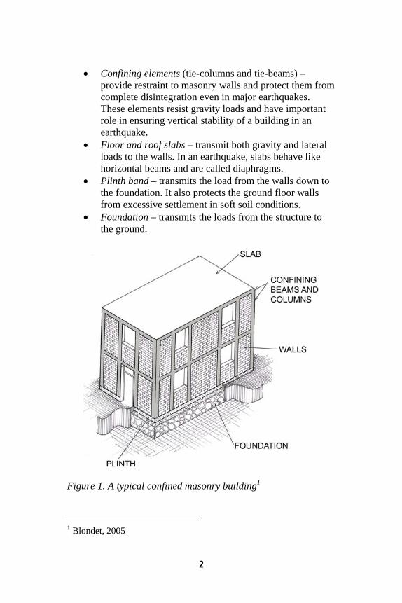
The structural components of a confined masonry building are (see Figure 1):
• Masonry walls – transmit the gravity load from the slab(s) above down to the foundation. The walls act as bracing panels, which resist horizontal earthquake forces. The walls must be confined by concrete tie-beams and tie-columns to ensure satisfactory earthquake performance.
2
• Confining elements (tie-columns and tie-beams) – provide restraint to masonry walls and protect them from complete disintegration even in major earthquakes. These elements resist gravity loads and have important role in ensuring vertical stability of a building in an earthquake.
• Floor and roof slabs – transmit both gravity and lateral loads to the walls. In an earthquake, slabs behave like horizontal beams and are called diaphragms.
• Plinth band – transmits the load from the walls down to the foundation. It also protects the ground floor walls from excessive settlement in soft soil conditions.
• Foundation – transmits the loads from the structure to the ground.
Figure 1. A typical confined masonry building1
1 Blondet, 2005
3
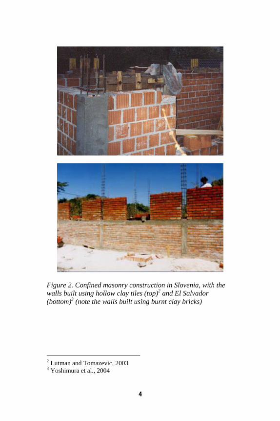
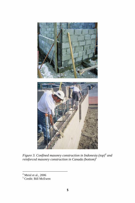
It should be noted that the term “confined masonry” is used in a general sense for different forms of masonry construction reinforced with additional steel, timber, or concrete elements. However, the focus of this document is on clay brick or concrete block masonry walls “confined” with reinforced concrete tie-beams and tie-columns. Confined masonry walls can be constructed using different types of masonry units. Figure 2 shows construction from Slovenia built using hollow clay tiles and confined masonry construction from El Salvador built using burnt clay bricks, while Figure 3 (top) shows a confined masonry building from Indonesia built using concrete blocks. Confined masonry construction is somewhat similar to reinforced masonry. In reinforced masonry, vertical and horizontal reinforcement bars are provided to enhance the strength of masonry walls. Masonry units are usually hollow and are made of concrete or clay. Vertical reinforcement bars are placed in the hollow cores, which are subsequently grouted with a cement-based grout to protect the reinforcement from corrosion. Vertical reinforcement is placed at the wall corners and intersections, around the openings, and additional locations depending on expected seismic loads. Horizontal reinforcement is provided in the form of ladder reinforcement (placed in horizontal joints) or deformed reinforcement bars placed in bond beams typically located at the lintel level (similar to RC lintel bands in Indian masonry construction). In reinforced masonry construction, vertical reinforcement mainly resists the effects of axial load and bending, whereas horizontal reinforcement resists shear. In confined masonry, the reinforcement is concentrated in vertical and horizontal confining elements whereas the masonry walls are usually free of reinforcement. Figure 3 illustrates the difference between reinforced and confined masonry construction (note that both examples use concrete block construction).
4
Figure 2. Confined masonry construction in Slovenia, with the walls built using hollow clay tiles (top)2 and El Salvador (bottom)3 (note the walls built using burnt clay bricks)
2 Lutman and Tomazevic, 2003 3 Yoshimura et al., 2004
5
Figure 3. Confined masonry construction in Indonesia (top)4 and reinforced masonry construction in Canada (bottom)5
4 Meisl et al., 2006 5 Credit: Bill McEwen

6
7
2. How is Confined Masonry Different from RC Frame Construction?
The appearance of a finished confined masonry construction and a RC frame construction with masonry infills may look alike to lay people, however these two construction systems are substantially different. The main differences are related to the construction sequence, as well as to the manner in which these structures resist gravity and lateral loads. These differences are summarized in Table 1 and are illustrated by diagrams in Figure 4. Examples of RC frame and confined masonry construction from Cambodia and Mexico respectively are shown in Figure 5. Table 1. A comparison between the confined masonry and RC frame construction
Confined masonry construction RC frame construction Gravity and lateral load-resisting system
Masonry walls are the main load bearing elements and are expected to resist both gravity and lateral loads. Confining elements (tie-beams and tie-columns) are significantly smaller in size than RC beams and columns.
RC frames resist both gravity and lateral loads through their relatively large beams, columns, and their connections. Masonry infills are not load-bearing walls.
Foundation construction
Strip footing beneath the wall and the RC plinth band
Isolated footing beneath each column
Superstructure construction sequence
1. Masonry walls are constructed first.
2. Subsequently, tie-columns are cast in place.
3. Finally, tie-beams are constructed on top of the walls, simultaneously with the floor/roof slab construction.
1. The frame is constructed first.
2. Masonry walls are constructed at a later stage and are not bonded to the frame members; these walls are nonstructural, that is, non-load bearing walls.
8
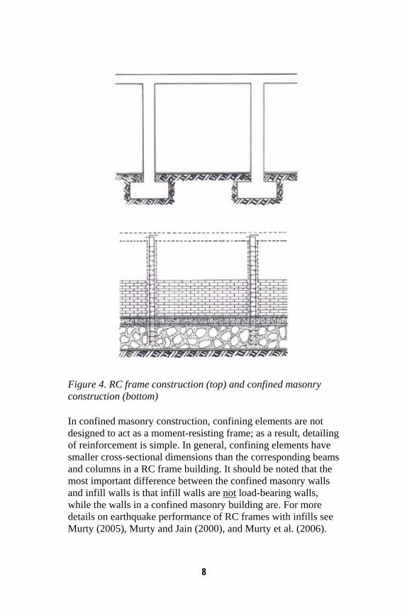
Figure 4. RC frame construction (top) and confined masonry construction (bottom) In confined masonry construction, confining elements are not designed to act as a moment-resisting frame; as a result, detailing of reinforcement is simple. In general, confining elements have smaller cross-sectional dimensions than the corresponding beams and columns in a RC frame building. It should be noted that the most important difference between the confined masonry walls and infill walls is that infill walls are not load-bearing walls, while the walls in a confined masonry building are. For more details on earthquake performance of RC frames with infills see Murty (2005), Murty and Jain (2000), and Murty et al. (2006).
9
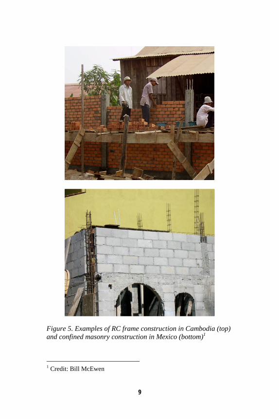
Figure 5. Examples of RC frame construction in Cambodia (top) and confined masonry construction in Mexico (bottom)1
1 Credit: Bill McEwen
10
In some instances, there is a thin line between RC frame and confined masonry construction practices. Some RC frame buildings may use smaller column sizes and/or inadequate reinforcement detailing for effective moment transfer between the beams and the columns. It should be noted that, in spite of a few details typical for confined masonry construction, such RC buildings are likely not going to demonstrate good seismic performance characteristic for properly built confined masonry; instead, they are going to perform poorly in an earthquake due to inadequate design and/or construction. A transition from RC frame to confined masonry construction in most cases leads to savings related to concrete cost, since confining elements are smaller in size than the corresponding RC frame members. Also, less reinforcement and less intricate detailing is required for confined masonry construction than for RC frame construction. Therefore, in this case “less means more”. Improved seismic performance will be achieved by reducing the amount of materials and labour typically associated with the RC frame construction practice and by following guidelines for confined masonry construction discussed in this document.
11
3. Worldwide Applications Confined masonry construction has evolved though an informal process based on its satisfactory performance in past earthquakes. The first reported use of confined masonry construction was in the reconstruction of buildings destroyed by the 1908 Messina, Italy earthquake (Magnitude 7.2), which killed over 70,000 people. The practice of confined masonry construction started in Chile in the 1930’s after the 1928 Talca earthquake (Magnitude 8.0) that affected a significant number of unreinforced masonry buildings. Subsequently, the 1939 earthquake (Magnitude 7.8) that struck the mid-southern region of the country, revealed very good performance of confined masonry buildings (Moroni et al., 2004). Confined masonry construction was introduced in Mexico City, Mexico in the 1940’s to control the wall cracking caused by large differential settlements under the soft soil conditions. Several years later, this system became popular in other areas of highest seismic hazard in Mexico due to its excellent earthquake performance (Meli and Alcocer, 2004). The use of confined masonry in Colombia dates from the 1930’s and it is currently widely used for housing construction, from single-storey dwellings to five-storey apartment buildings (Garcia and Yamin, 1994). Over the last 30 years, confined masonry construction has been practiced in Mediterranean Europe (Italy, Slovenia, Serbia), Latin America (Mexico, Chile, Peru, Argentina, and other countries), the Middle East (Iran), south Asia (Indonesia), and the Far East (China). A world map showing the areas of high seismic risk is presented in Figure 6. It is important to note that confined masonry construction is practiced in the countries and regions of extremely high seismic risk. Several examples of confined masonry construction around the world, from Argentina, Chile, Iran, Peru, Serbia and Slovenia, are featured in the World Housing Encyclopedia (EERI/IAEE, 2000).
12
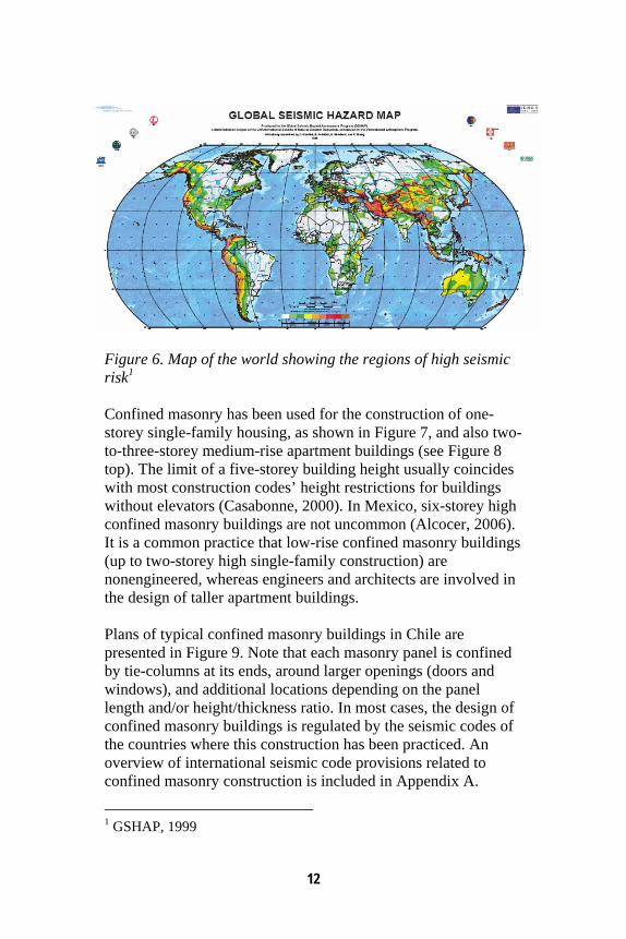
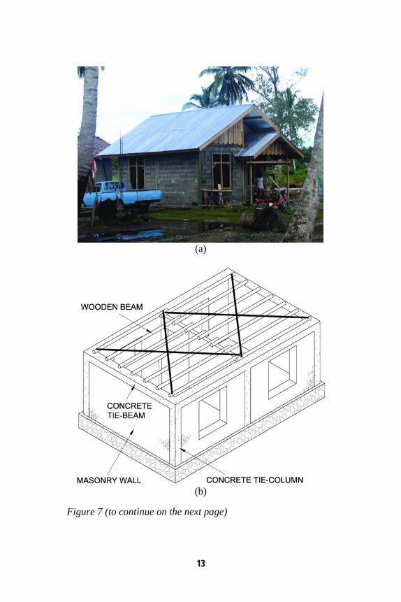
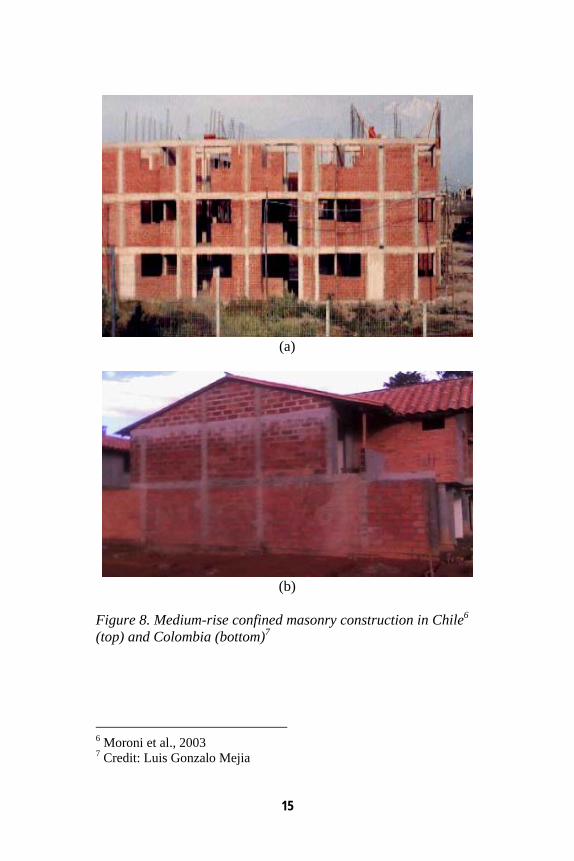
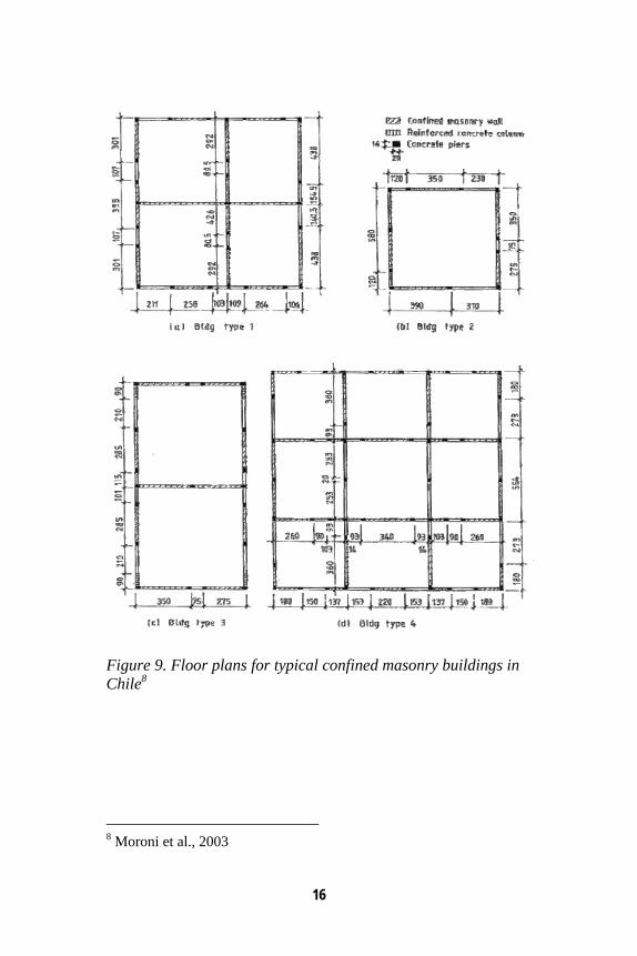
Figure 6. Map of the world showing the regions of high seismic risk1 Confined masonry has been used for the construction of one-storey single-family housing, as shown in Figure 7, and also two-to-three-storey medium-rise apartment buildings (see Figure 8 top). The limit of a five-storey building height usually coincides with most construction codes’ height restrictions for buildings without elevators (Casabonne, 2000). In Mexico, six-storey high confined masonry buildings are not uncommon (Alcocer, 2006). It is a common practice that low-rise confined masonry buildings (up to two-storey high single-family construction) are nonengineered, whereas engineers and architects are involved in the design of taller apartment buildings. Plans of typical confined masonry buildings in Chile are presented in Figure 9. Note that each masonry panel is confined by tie-columns at its ends, around larger openings (doors and windows), and additional locations depending on the panel length and/or height/thickness ratio. In most cases, the design of confined masonry buildings is regulated by the seismic codes of the countries where this construction has been practiced. An overview of international seismic code provisions related to confined masonry construction is included in Appendix A.
1 GSHAP, 1999
13
(a)
(b)
Figure 7 (to continue on the next page)
14
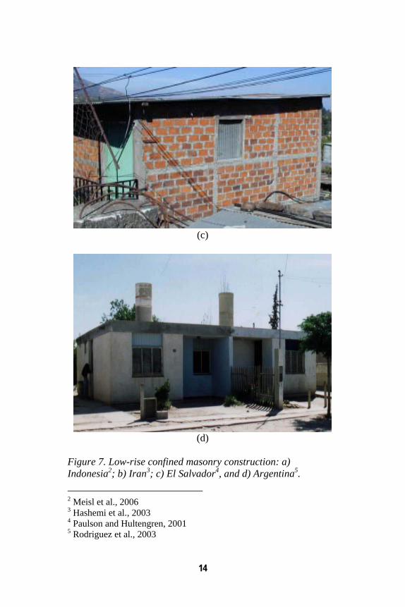
(c)
(d)
Figure 7. Low-rise confined masonry construction: a) Indonesia2; b) Iran3; c) El Salvador4, and d) Argentina5. 2 Meisl et al., 2006 3 Hashemi et al., 2003 4 Paulson and Hultengren, 2001 5 Rodriguez et al., 2003
15
(a)
(b)
Figure 8. Medium-rise confined masonry construction in Chile6 (top) and Colombia (bottom)7 6 Moroni et al., 2003 7 Credit: Luis Gonzalo Mejia
16
Figure 9. Floor plans for typical confined masonry buildings in Chile8
8 Moroni et al., 2003
17
4. How Confined Masonry Buildings Resist Earthquake Effects
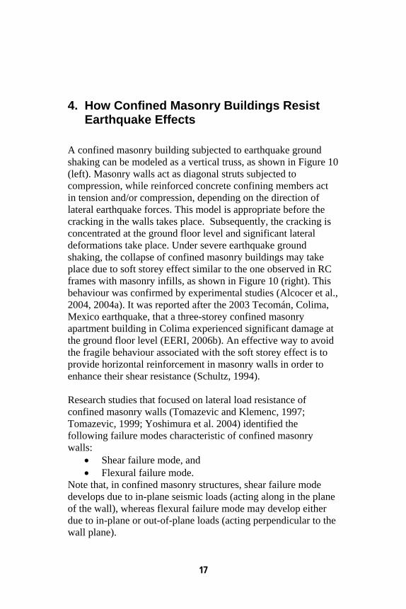
A confined masonry building subjected to earthquake ground shaking can be modeled as a vertical truss, as shown in Figure 10 (left). Masonry walls act as diagonal struts subjected to compression, while reinforced concrete confining members act in tension and/or compression, depending on the direction of lateral earthquake forces. This model is appropriate before the cracking in the walls takes place. Subsequently, the cracking is concentrated at the ground floor level and significant lateral deformations take place. Under severe earthquake ground shaking, the collapse of confined masonry buildings may take place due to soft storey effect similar to the one observed in RC frames with masonry infills, as shown in Figure 10 (right). This behaviour was confirmed by experimental studies (Alcocer et al., 2004, 2004a). It was reported after the 2003 Tecomán, Colima, Mexico earthquake, that a three-storey confined masonry apartment building in Colima experienced significant damage at the ground floor level (EERI, 2006b). An effective way to avoid the fragile behaviour associated with the soft storey effect is to provide horizontal reinforcement in masonry walls in order to enhance their shear resistance (Schultz, 1994). Research studies that focused on lateral load resistance of confined masonry walls (Tomazevic and Klemenc, 1997; Tomazevic, 1999; Yoshimura et al. 2004) identified the following failure modes characteristic of confined masonry walls:
• Shear failure mode, and • Flexural failure mode.
Note that, in confined masonry structures, shear failure mode develops due to in-plane seismic loads (acting along in the plane of the wall), whereas flexural failure mode may develop either due to in-plane or out-of-plane loads (acting perpendicular to the wall plane).
18
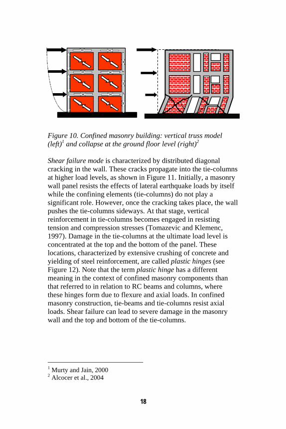
Figure 10. Confined masonry building: vertical truss model (left)1 and collapse at the ground floor level (right)2 Shear failure mode is characterized by distributed diagonal cracking in the wall. These cracks propagate into the tie-columns at higher load levels, as shown in Figure 11. Initially, a masonry wall panel resists the effects of lateral earthquake loads by itself while the confining elements (tie-columns) do not play a significant role. However, once the cracking takes place, the wall pushes the tie-columns sideways. At that stage, vertical reinforcement in tie-columns becomes engaged in resisting tension and compression stresses (Tomazevic and Klemenc, 1997). Damage in the tie-columns at the ultimate load level is concentrated at the top and the bottom of the panel. These locations, characterized by extensive crushing of concrete and yielding of steel reinforcement, are called plastic hinges (see Figure 12). Note that the term plastic hinge has a different meaning in the context of confined masonry components than that referred to in relation to RC beams and columns, where these hinges form due to flexure and axial loads. In confined masonry construction, tie-beams and tie-columns resist axial loads. Shear failure can lead to severe damage in the masonry wall and the top and bottom of the tie-columns.
1 Murty and Jain, 2000 2 Alcocer et al., 2004
19
Figure 11. Shear failure of confined masonry walls3
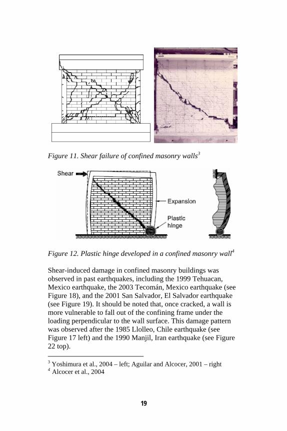
Figure 12. Plastic hinge developed in a confined masonry wall4 Shear-induced damage in confined masonry buildings was observed in past earthquakes, including the 1999 Tehuacan, Mexico earthquake, the 2003 Tecomán, Mexico earthquake (see Figure 18), and the 2001 San Salvador, El Salvador earthquake (see Figure 19). It should be noted that, once cracked, a wall is more vulnerable to fall out of the confining frame under the loading perpendicular to the wall surface. This damage pattern was observed after the 1985 Llolleo, Chile earthquake (see Figure 17 left) and the 1990 Manjil, Iran earthquake (see Figure 22 top). 3 Yoshimura et al., 2004 – left; Aguilar and Alcocer, 2001 – right 4 Alcocer et al., 2004
20
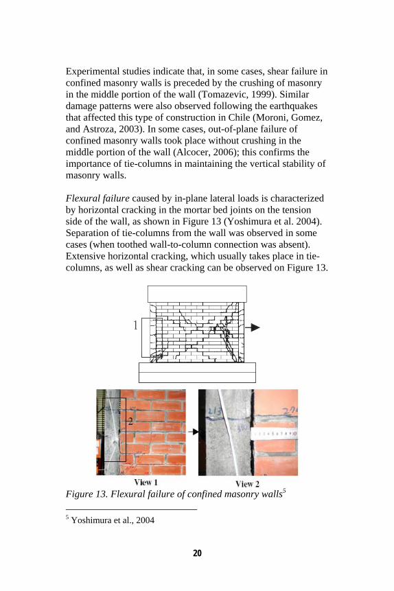
Experimental studies indicate that, in some cases, shear failure in confined masonry walls is preceded by the crushing of masonry in the middle portion of the wall (Tomazevic, 1999). Similar damage patterns were also observed following the earthquakes that affected this type of construction in Chile (Moroni, Gomez, and Astroza, 2003). In some cases, out-of-plane failure of confined masonry walls took place without crushing in the middle portion of the wall (Alcocer, 2006); this confirms the importance of tie-columns in maintaining the vertical stability of masonry walls. Flexural failure caused by in-plane lateral loads is characterized by horizontal cracking in the mortar bed joints on the tension side of the wall, as shown in Figure 13 (Yoshimura et al. 2004). Separation of tie-columns from the wall was observed in some cases (when toothed wall-to-column connection was absent). Extensive horizontal cracking, which usually takes place in tie-columns, as well as shear cracking can be observed on Figure 13.
Figure 13. Flexural failure of confined masonry walls5 5 Yoshimura et al., 2004
21
Experimental studies have shown that, irrespective of the failure mechanism, tie-columns resist the major portion of gravity load when masonry walls suffer severe damage (this is due to their high axial stiffness and load resistance). The failure of a tie-column usually takes place when cracks propagate from the masonry wall into the tie-column and shear it off. Subsequently, the vertical stability of the entire wall is compromised. Experimental studies have shown that vertical strains in the confined masonry walls decrease at an increased damage level, thereby indicating that a major portion of the gravity load is resisted by tie-columns. This finding confirms the notion that tie-columns have a critical role in resisting the gravity load in damaged confined masonry buildings and ensuring their vertical stability (Alcocer, 2006).

22
23
5. Key Factors Influencing Seismic Resistance of Confined Masonry Structures
5.1 Wall Density
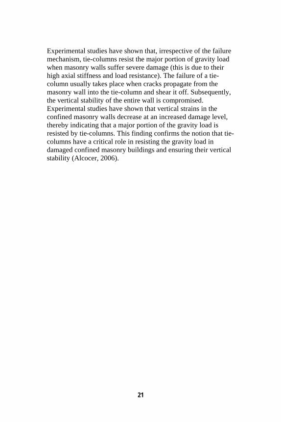
Wall density is believed to be one of the key parameters influencing the seismic performance of confined masonry buildings. It can be determined as the transverse area of walls in each principal direction divided by the total floor area of the building. In Mexico, a simplified procedure was developed to determine the required wall density for buildings in which the wall seismic resistance is governed by shear effects (Meli, 1994). After the 1985 Mexico earthquake, the Mexico City Building Code imposed more stringent wall density requirements for masonry buildings. These requirements were based on the fact that, due to the reality of Mexican construction practice, it was not possible to prescribe the use of higher strength materials or the provision of reinforcement as an alternative approach for increasing earthquake resistance. Therefore, after the 1985 earthquake, the code required a 40% increase in the design seismic resistance; this resulted in a significant increase in wall density requirements in confined masonry construction. As an example, for a five-storey building in Mexico City, it is now required to provide wall density of around 6% in each direction, whereas in the areas of highest seismic risk (the State of Guererro), this value is close to 10%. A diagram showing the wall density requirements in Mexico is presented in Figure 14 (Meli, 1994). A comprehensive study done in Chile after the 1985 Llolleo earthquake showed that the extent of damage in masonry buildings was related to the wall density in the following way: buildings with a wall density of less than 0.5% sustained severe damage, while the buildings with wall density of 1.15% sustained only light damage. The survey performed in Chile showed that over 50% of surveyed confined masonry buildings
24
have a wall density of over 1.15%. An average wall density for confined masonry buildings in Chile is estimated to be on the order of 3.3% (Moroni, Astroza, and Acevedo, 2004).
Figure 14. Wall density (d) versus the number of stories for confined masonry buildings on soft soil conditions in Mexico1
5.2 Masonry Units and Mortar
The tests have shown that the lateral load resistance of confined masonry walls strongly depends on the strength of the masonry units and the mortar used. The walls built using low-strength bricks or ungrouted hollow block units had the lowest strength while the ones built using grouted or solid units had the largest strength. However, the use of grouted and solid units results in an increase both in wall mass and seismic loads. Also, the weaker the mortar the lower the masonry strength (due to the unit-mortar interaction, the masonry strength is always lower than the unit strength). Test results have also shown that there is no significant difference in strength between unreinforced and confined masonry wall specimens with the same geometry and material properties (Alcocer and Klingner, 1994).
1 Meli, 1994
25
5.3 Tie-Columns
Tie-columns significantly influence the ductility and stability of cracked confined masonry walls. Note that the effect of tie-columns on increasing lateral resistance of confined masonry structures has only recently been recognized (Alcocer, 2006). The provision of closely spaced transverse reinforcement (ties) at the top and bottom ends of tie-columns results in improved wall stability and ductility in the post-cracking stage (Alcocer and Klingner, 1994). 5.4 Horizontal Wall Reinforcement
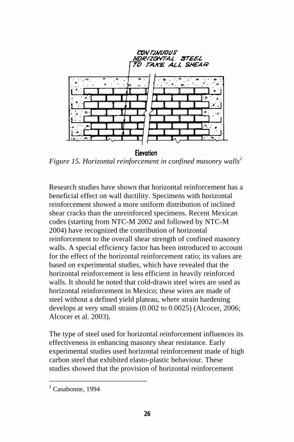
In many countries where confined masonry construction is practiced, reinforcement is usually not provided in masonry walls. However, in four-to-five storey construction in Peru there is a tendency to provide horizontal joint reinforcement in the form of one or two wires laid in the mortar bed joints (Casabonne, 1994), as shown in Figure 15. The Mexican Code NTC-M 2004 prescribes that the horizontal reinforcement, when provided, be placed continuously along the wall length. Horizontal rebars should be anchored into the tie-columns; the anchorage should be provided with 90o hooks at the far end of the tie-column (see Figure 15). The hooks should be embedded in the concrete within the tie-column (note that the tie-column reinforcement was omitted from the figure). The bar diameter should be larger than 3.5 mm and less than ¾ the joint thickness.
26
Figure 15. Horizontal reinforcement in confined masonry walls2 Research studies have shown that horizontal reinforcement has a beneficial effect on wall ductility. Specimens with horizontal reinforcement showed a more uniform distribution of inclined shear cracks than the unreinforced specimens. Recent Mexican codes (starting from NTC-M 2002 and followed by NTC-M 2004) have recognized the contribution of horizontal reinforcement to the overall shear strength of confined masonry walls. A special efficiency factor has been introduced to account for the effect of the horizontal reinforcement ratio; its values are based on experimental studies, which have revealed that the horizontal reinforcement is less efficient in heavily reinforced walls. It should be noted that cold-drawn steel wires are used as horizontal reinforcement in Mexico; these wires are made of steel without a defined yield plateau, where strain hardening develops at very small strains (0.002 to 0.0025) (Alcocer, 2006; Alcocer et al. 2003). The type of steel used for horizontal reinforcement influences its effectiveness in enhancing masonry shear resistance. Early experimental studies used horizontal reinforcement made of high carbon steel that exhibited elasto-plastic behaviour. These studies showed that the provision of horizontal reinforcement 2 Casabonne, 1994
27
does not result in a significant strength increase (Alcocer and Klingner, 1994; Aguilar et al. 1996). Also, the specimens with intermediate tie-beams placed at the wall midheight, like the one shown in Figure 7 (c), did not show satisfactory behaviour, since the wall panel above the intermediate tie-beam caused the failure in tie-columns. In some countries, like Costa Rica (Casabonne, 1994) and El Salvador (EERI, 2001a), intermediate tie-beams are used in confined masonry construction practice. 5.5 Openings
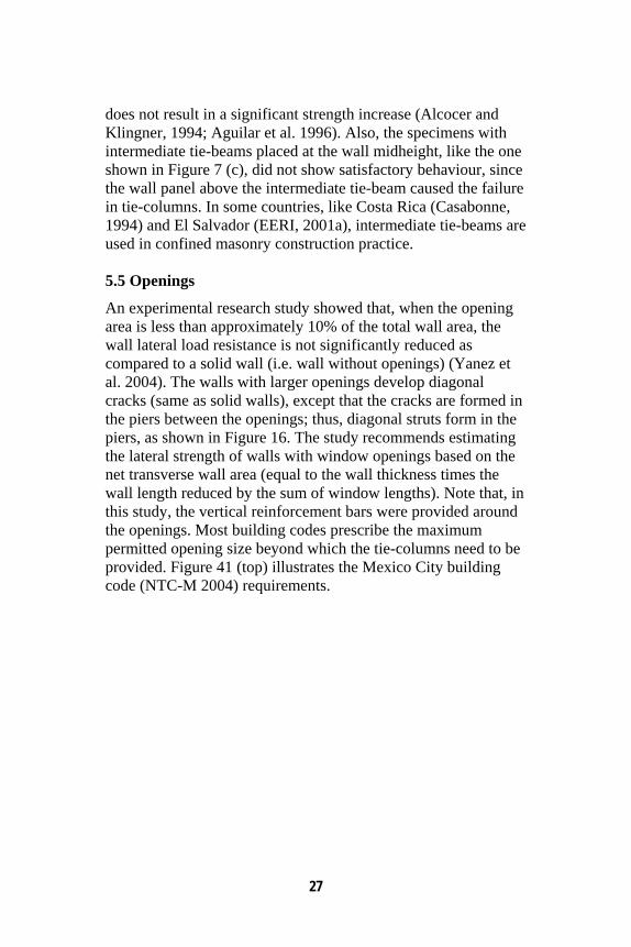
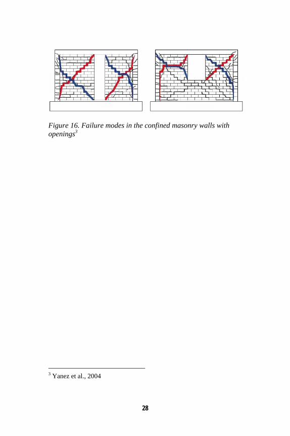
An experimental research study showed that, when the opening area is less than approximately 10% of the total wall area, the wall lateral load resistance is not significantly reduced as compared to a solid wall (i.e. wall without openings) (Yanez et al. 2004). The walls with larger openings develop diagonal cracks (same as solid walls), except that the cracks are formed in the piers between the openings; thus, diagonal struts form in the piers, as shown in Figure 16. The study recommends estimating the lateral strength of walls with window openings based on the net transverse wall area (equal to the wall thickness times the wall length reduced by the sum of window lengths). Note that, in this study, the vertical reinforcement bars were provided around the openings. Most building codes prescribe the maximum permitted opening size beyond which the tie-columns need to be provided. Figure 41 (top) illustrates the Mexico City building code (NTC-M 2004) requirements.
28
Figure 16. Failure modes in the confined masonry walls with openings3
3 Yanez et al., 2004
29
6. Earthquake Performance of Confined Masonry Construction
Confined masonry buildings have demonstrated satisfactory performance in past earthquakes. In general, buildings of this type do experience some damage in earthquakes, however when properly designed and constructed they are able to sustain earthquake effects without collapse. Latin America is certainly a region of the world where confined masonry construction is widely used and was tested in several significant earthquakes associated with the region’s high seismic risk. According to Schultz (1994), low-rise confined masonry buildings have performed very well in past Latin American earthquakes. This applies to buildings regular in plan and elevation, which are lightly loaded and have rather large wall density. In such cases, confined masonry tends to be quite forgiving of minor design and construction flaws, as well as material deficiencies. Poor seismic performance has been noted only when gross construction errors, design flaws, or material deficiencies have been introduced in the building design and construction process. Poor performance is usually associated with tie-column omissions, discontinuous tie-beams, inadequate diaphragm connections, and inappropriate structural configuration. Seismic performance of confined masonry construction in Latin America and other parts of the world will be discussed in this section. The earliest reports describing the earthquake performance of confined masonry buildings date back to the 1939 earthquake (magnitude 7.8) in Chile. In Chillán, where a Modified Mercalli Intensity (MMI) of IX was reported, over 50% of all inspected confined masonry buildings sustained the earthquake without any damage, whereas around 60% of unreinforced masonry buildings either partially or entirely collapsed, resulting in a death toll of 30,000. Subsequently, the 1985 Llolleo earthquake (magnitude 7.8) with an epicentre in the central part of Chile, caused the collapse of 66,000 dwellings and damage to another
30
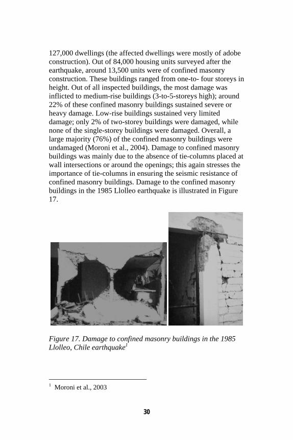
127,000 dwellings (the affected dwellings were mostly of adobe construction). Out of 84,000 housing units surveyed after the earthquake, around 13,500 units were of confined masonry construction. These buildings ranged from one-to- four storeys in height. Out of all inspected buildings, the most damage was inflicted to medium-rise buildings (3-to-5-storeys high); around 22% of these confined masonry buildings sustained severe or heavy damage. Low-rise buildings sustained very limited damage; only 2% of two-storey buildings were damaged, while none of the single-storey buildings were damaged. Overall, a large majority (76%) of the confined masonry buildings were undamaged (Moroni et al., 2004). Damage to confined masonry buildings was mainly due to the absence of tie-columns placed at wall intersections or around the openings; this again stresses the importance of tie-columns in ensuring the seismic resistance of confined masonry buildings. Damage to the confined masonry buildings in the 1985 Llolleo earthquake is illustrated in Figure 17.
Figure 17. Damage to confined masonry buildings in the 1985 Llolleo, Chile earthquake1
1 Moroni et al., 2003
31
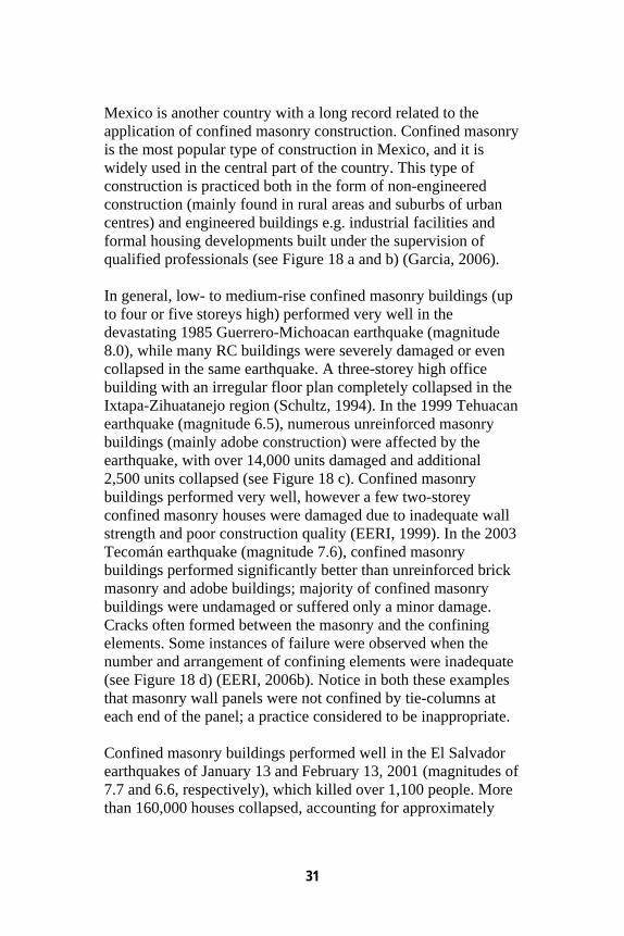
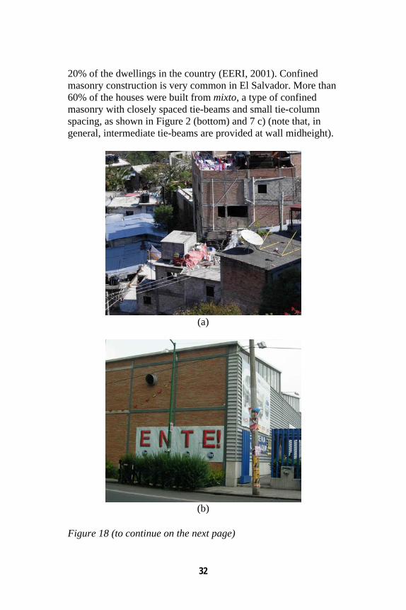
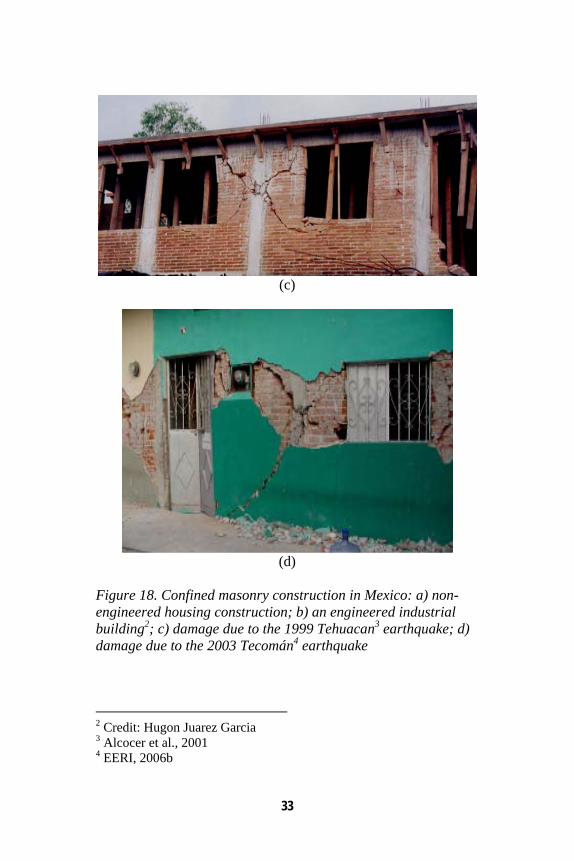
Mexico is another country with a long record related to the application of confined masonry construction. Confined masonry is the most popular type of construction in Mexico, and it is widely used in the central part of the country. This type of construction is practiced both in the form of non-engineered construction (mainly found in rural areas and suburbs of urban centres) and engineered buildings e.g. industrial facilities and formal housing developments built under the supervision of qualified professionals (see Figure 18 a and b) (Garcia, 2006). In general, low- to medium-rise confined masonry buildings (up to four or five storeys high) performed very well in the devastating 1985 Guerrero-Michoacan earthquake (magnitude 8.0), while many RC buildings were severely damaged or even collapsed in the same earthquake. A three-storey high office building with an irregular floor plan completely collapsed in the Ixtapa-Zihuatanejo region (Schultz, 1994). In the 1999 Tehuacan earthquake (magnitude 6.5), numerous unreinforced masonry buildings (mainly adobe construction) were affected by the earthquake, with over 14,000 units damaged and additional 2,500 units collapsed (see Figure 18 c). Confined masonry buildings performed very well, however a few two-storey confined masonry houses were damaged due to inadequate wall strength and poor construction quality (EERI, 1999). In the 2003 Tecomán earthquake (magnitude 7.6), confined masonry buildings performed significantly better than unreinforced brick masonry and adobe buildings; majority of confined masonry buildings were undamaged or suffered only a minor damage. Cracks often formed between the masonry and the confining elements. Some instances of failure were observed when the number and arrangement of confining elements were inadequate (see Figure 18 d) (EERI, 2006b). Notice in both these examples that masonry wall panels were not confined by tie-columns at each end of the panel; a practice considered to be inappropriate. Confined masonry buildings performed well in the El Salvador earthquakes of January 13 and February 13, 2001 (magnitudes of 7.7 and 6.6, respectively), which killed over 1,100 people. More than 160,000 houses collapsed, accounting for approximately
32
20% of the dwellings in the country (EERI, 2001). Confined masonry construction is very common in El Salvador. More than 60% of the houses were built from mixto, a type of confined masonry with closely spaced tie-beams and small tie-column spacing, as shown in Figure 2 (bottom) and 7 c) (note that, in general, intermediate tie-beams are provided at wall midheight).
(a)
(b)
Figure 18 (to continue on the next page)
33
(c)
(d)
Figure 18. Confined masonry construction in Mexico: a) non-engineered housing construction; b) an engineered industrial building2; c) damage due to the 1999 Tehuacan3 earthquake; d) damage due to the 2003 Tecomán4 earthquake
2 Credit: Hugon Juarez Garcia 3 Alcocer et al., 2001 4 EERI, 2006b
34
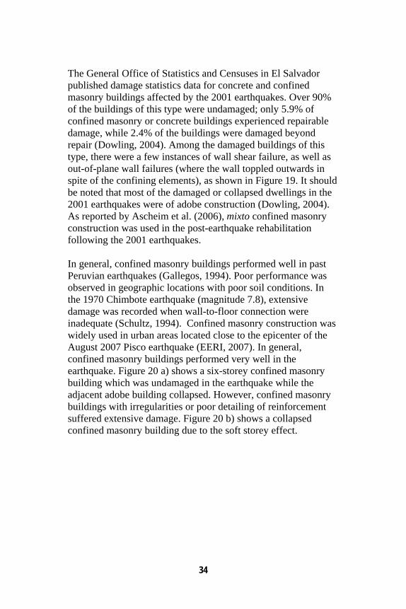
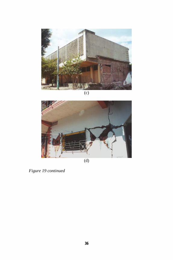
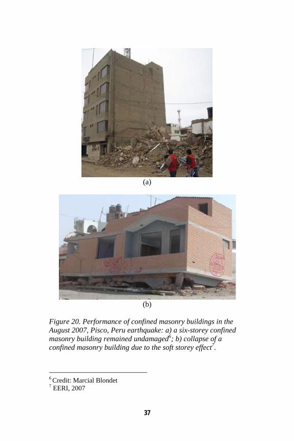
The General Office of Statistics and Censuses in El Salvador published damage statistics data for concrete and confined masonry buildings affected by the 2001 earthquakes. Over 90% of the buildings of this type were undamaged; only 5.9% of confined masonry or concrete buildings experienced repairable damage, while 2.4% of the buildings were damaged beyond repair (Dowling, 2004). Among the damaged buildings of this type, there were a few instances of wall shear failure, as well as out-of-plane wall failures (where the wall toppled outwards in spite of the confining elements), as shown in Figure 19. It should be noted that most of the damaged or collapsed dwellings in the 2001 earthquakes were of adobe construction (Dowling, 2004). As reported by Ascheim et al. (2006), mixto confined masonry construction was used in the post-earthquake rehabilitation following the 2001 earthquakes. In general, confined masonry buildings performed well in past Peruvian earthquakes (Gallegos, 1994). Poor performance was observed in geographic locations with poor soil conditions. In the 1970 Chimbote earthquake (magnitude 7.8), extensive damage was recorded when wall-to-floor connection were inadequate (Schultz, 1994). Confined masonry construction was widely used in urban areas located close to the epicenter of the August 2007 Pisco earthquake (EERI, 2007). In general, confined masonry buildings performed very well in the earthquake. Figure 20 a) shows a six-storey confined masonry building which was undamaged in the earthquake while the adjacent adobe building collapsed. However, confined masonry buildings with irregularities or poor detailing of reinforcement suffered extensive damage. Figure 20 b) shows a collapsed confined masonry building due to the soft storey effect.
35
(a)
(b)
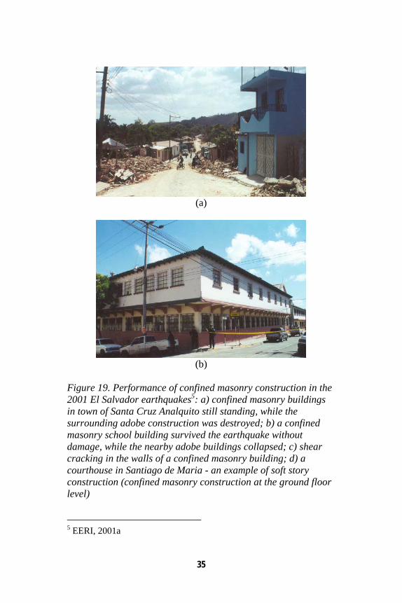
Figure 19. Performance of confined masonry construction in the 2001 El Salvador earthquakes5: a) confined masonry buildings in town of Santa Cruz Analquito still standing, while the surrounding adobe construction was destroyed; b) a confined masonry school building survived the earthquake without damage, while the nearby adobe buildings collapsed; c) shear cracking in the walls of a confined masonry building; d) a courthouse in Santiago de Maria - an example of soft story construction (confined masonry construction at the ground floor level)
5 EERI, 2001a
36
(c)
(d)
Figure 19 continued
37
(a)
(b)
Figure 20. Performance of confined masonry buildings in the August 2007, Pisco, Peru earthquake: a) a six-storey confined masonry building remained undamaged6; b) collapse of a confined masonry building due to the soft storey effect7.
6 Credit: Marcial Blondet 7 EERI, 2007
38
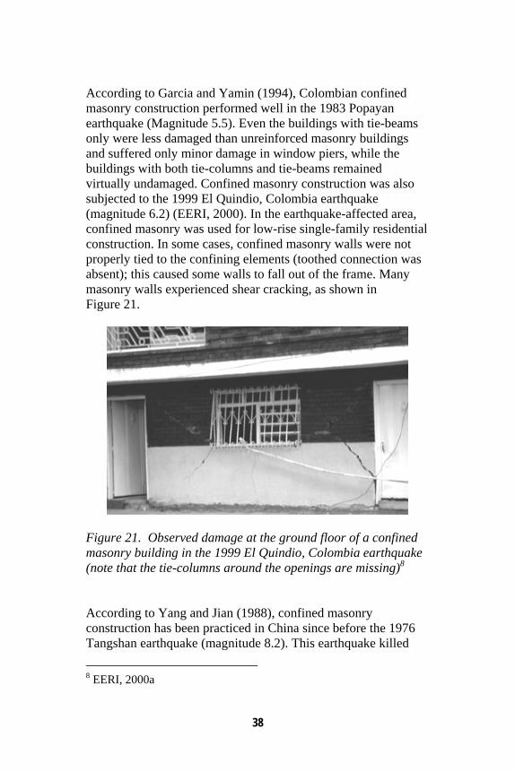
According to Garcia and Yamin (1994), Colombian confined masonry construction performed well in the 1983 Popayan earthquake (Magnitude 5.5). Even the buildings with tie-beams only were less damaged than unreinforced masonry buildings and suffered only minor damage in window piers, while the buildings with both tie-columns and tie-beams remained virtually undamaged. Confined masonry construction was also subjected to the 1999 El Quindio, Colombia earthquake (magnitude 6.2) (EERI, 2000). In the earthquake-affected area, confined masonry was used for low-rise single-family residential construction. In some cases, confined masonry walls were not properly tied to the confining elements (toothed connection was absent); this caused some walls to fall out of the frame. Many masonry walls experienced shear cracking, as shown in Figure 21.
Figure 21. Observed damage at the ground floor of a confined masonry building in the 1999 El Quindio, Colombia earthquake (note that the tie-columns around the openings are missing)8 According to Yang and Jian (1988), confined masonry construction has been practiced in China since before the 1976 Tangshan earthquake (magnitude 8.2). This earthquake killed
8 EERI, 2000a
39
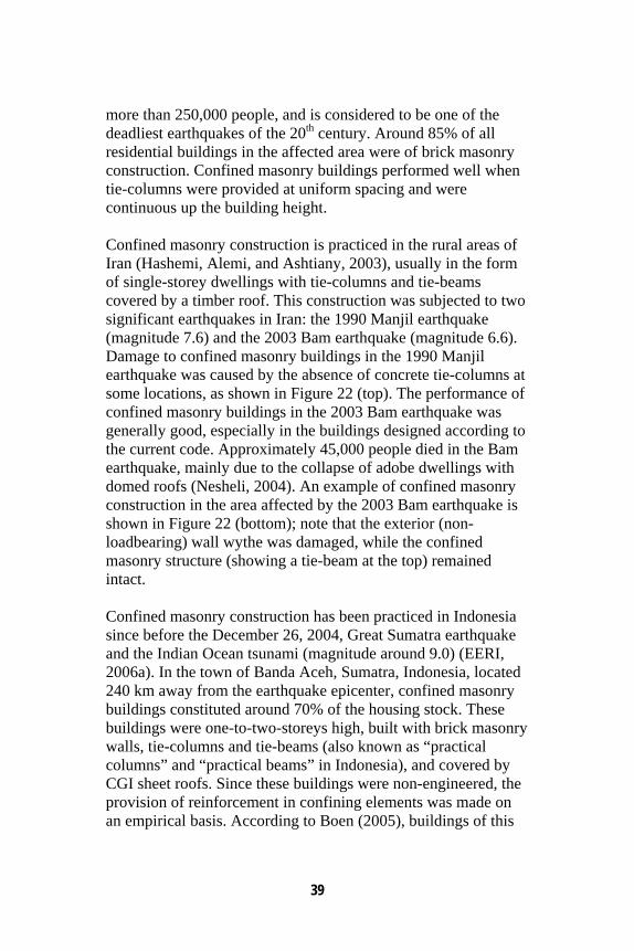
more than 250,000 people, and is considered to be one of the deadliest earthquakes of the 20th century. Around 85% of all residential buildings in the affected area were of brick masonry construction. Confined masonry buildings performed well when tie-columns were provided at uniform spacing and were continuous up the building height. Confined masonry construction is practiced in the rural areas of Iran (Hashemi, Alemi, and Ashtiany, 2003), usually in the form of single-storey dwellings with tie-columns and tie-beams covered by a timber roof. This construction was subjected to two significant earthquakes in Iran: the 1990 Manjil earthquake (magnitude 7.6) and the 2003 Bam earthquake (magnitude 6.6). Damage to confined masonry buildings in the 1990 Manjil earthquake was caused by the absence of concrete tie-columns at some locations, as shown in Figure 22 (top). The performance of confined masonry buildings in the 2003 Bam earthquake was generally good, especially in the buildings designed according to the current code. Approximately 45,000 people died in the Bam earthquake, mainly due to the collapse of adobe dwellings with domed roofs (Nesheli, 2004). An example of confined masonry construction in the area affected by the 2003 Bam earthquake is shown in Figure 22 (bottom); note that the exterior (non-loadbearing) wall wythe was damaged, while the confined masonry structure (showing a tie-beam at the top) remained intact. Confined masonry construction has been practiced in Indonesia since before the December 26, 2004, Great Sumatra earthquake and the Indian Ocean tsunami (magnitude around 9.0) (EERI, 2006a). In the town of Banda Aceh, Sumatra, Indonesia, located 240 km away from the earthquake epicenter, confined masonry buildings constituted around 70% of the housing stock. These buildings were one-to-two-storeys high, built with brick masonry walls, tie-columns and tie-beams (also known as “practical columns” and “practical beams” in Indonesia), and covered by CGI sheet roofs. Since these buildings were non-engineered, the provision of reinforcement in confining elements was made on an empirical basis. According to Boen (2005), buildings of this
40
type did not collapse due to the earthquake shaking (although some damage in the walls was observed) – most damage was caused by the subsequent tsunami.
Figure 22. Damage to the confined masonry construction in Iran due to the 1990 Manjil earthquake9 (top) and the 2003 Bam earthquake10 (bottom) (note that the absence of a tie-column at the door jamb on the latter photo)
9 Hashemi et al., 2003 10 Zahrai and Heidarzadeh, 2004
41
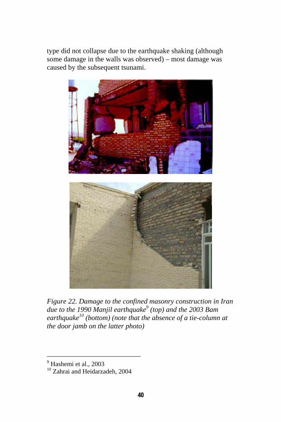
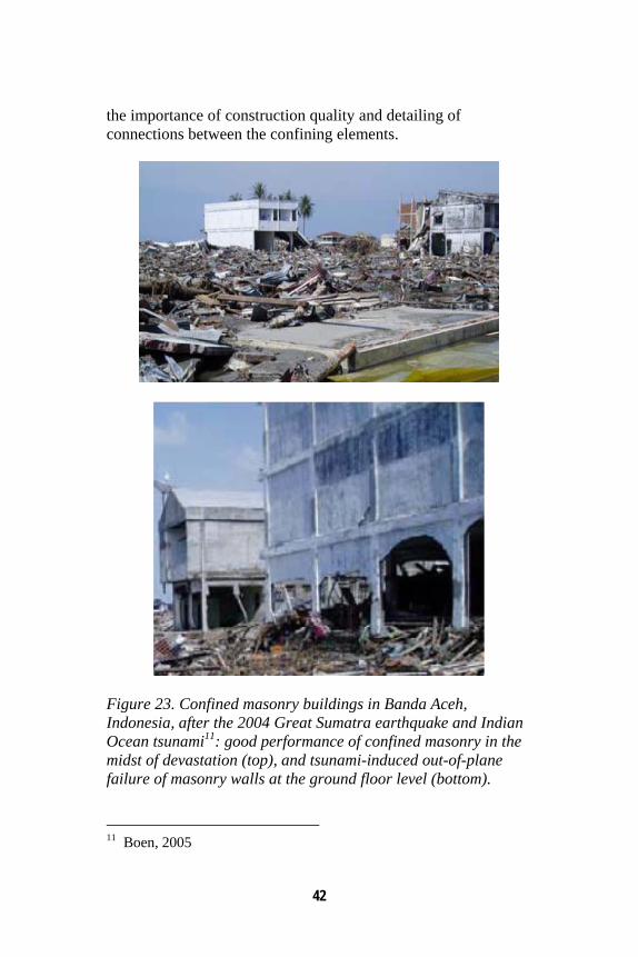
The causes of damage and collapse were attributed to the poor quality of materials and poor workmanship, thus resulting in poor detailing and poor quality concrete and masonry. The performance of confined masonry buildings in the 2004 earthquake and tsunami is illustrated in Figure 23 (top). Masonry walls at the ground floor level experienced out-of-plane failure due to the tsunami-induced water pressure, as shown in Figure 23 (bottom). Confined masonry was extensively used in housing reconstruction in Northern Sumatra following the earthquake and tsunami. Although the traditional post-and-beam timber construction has a good performance record in the past earthquakes, confined masonry seems to be the construction technology of choice for more prosperous communities and those of a higher social status (Meisl et al. 2006). Confined masonry buildings were also subjected to the March 28, 2005, Northern Sumatra earthquake of magnitude 8.7 (EERI, 2005). Buildings of this type were used for housing, schools, and community health centres. These buildings survived the shaking without collapse, although some cracking in the walls was observed. Cross-sectional dimensions for typical tie-columns were 120 mm by 120 mm with four 8 mm bars and 6 mm stirrups at 200 mm spacing (Boen, 2006). Confined masonry construction was affected by the September 12 and 13, 2007, Bengkulu earthquakes in Indonesia (EERI, 2007 a). The epicentre was off Sumatra island and the magnitudes were 8.4 and 7.9 respectively. Confined masonry was widely used for housing construction in the affected area. The walls were built of clay brick masonry and the confinement was provided by timber or RC tie-columns and tie-beams. Causes of damage in confined masonry construction were: inadequate connections between confining elements; poor quality of workmanship related to masonry construction; excessive openings resulting in out-of-plane failures; and slender walls leading to out-of-plane failure (typically 130 mm thick and over 3 m high in some cases). Overall, the performance of confined masonry construction in these earthquakes points out to
42
the importance of construction quality and detailing of connections between the confining elements.
Figure 23. Confined masonry buildings in Banda Aceh, Indonesia, after the 2004 Great Sumatra earthquake and Indian Ocean tsunami11: good performance of confined masonry in the midst of devastation (top), and tsunami-induced out-of-plane failure of masonry walls at the ground floor level (bottom).
11 Boen, 2005
43
7. Earthquake-Resistant Confined Masonry Construction: a Guideline
7.1 Background
As discussed above, confined masonry construction has typically performed well in past earthquakes worldwide, when built according to code requirements. Its satisfactory earthquake performance is due to the joint action of masonry walls and their confining elements. Properly designed and built confined masonry buildings are expected to experience damage in severe earthquakes, however a very few cases of collapse have been reported in past earthquakes worldwide. Conceptual considerations related to the architectural design of these buildings, as well as the key construction issues, are discussed below. Comprehensive guidelines related to architectural planning and construction of confined masonry buildings were developed in Peru by Blondet (2005), and can be downloaded from the Internet free of charge1. 7.2 Architectural Guideline
Experience from past earthquakes has confirmed that the initial conceptual design of a building is critical to its satisfactory performance during an earthquake. Architects play an important role in developing this conceptual design and in defining the overall shape, size and dimensions of a building. Structural engineers are responsible for providing numerical proof of structural safety and must work closely with architects to ensure that the design meets both structural and architectural requirements. Engineers are often not involved in design of low-rise buildings such as confined masonry buildings discussed in this document. When architects are involved, they work directly with contractors throughout the construction process. Therefore,
1 http://www.world-housing.net/Tutorials/Tutorial.asp
44
it is of critical importance for architects and builders to become familiar with and to follow simple rules related to the design and construction of confined masonry buildings -- this will also facilitate their communication with engineers. The top 10 requirements related to the architectural design of earthquake-resistant confined masonry buildings are outlined below. Building Layout
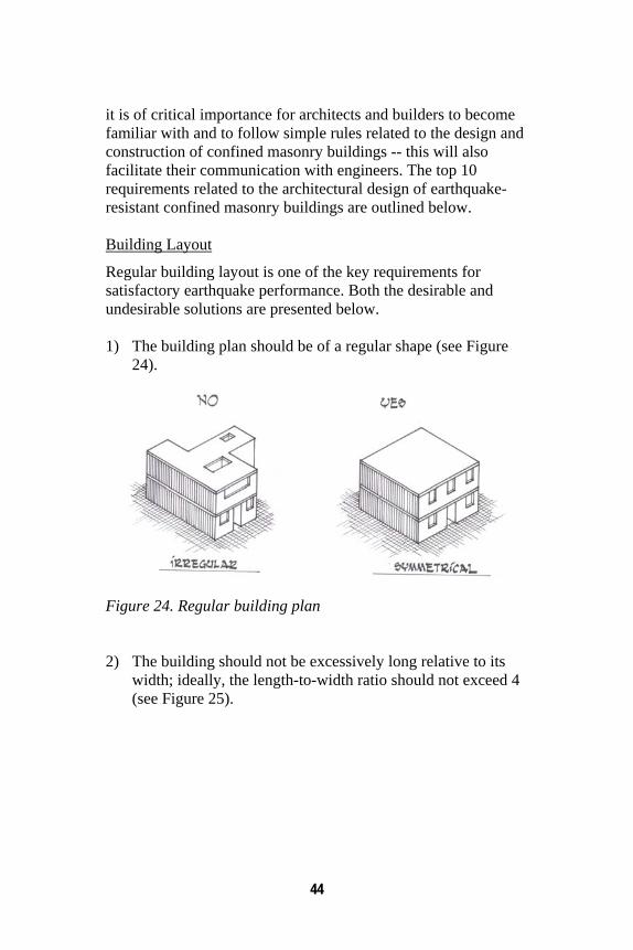
Regular building layout is one of the key requirements for satisfactory earthquake performance. Both the desirable and undesirable solutions are presented below. 1) The building plan should be of a regular shape (see Figure
24).
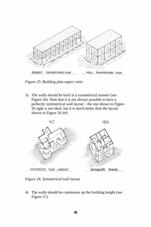
Figure 24. Regular building plan 2) The building should not be excessively long relative to its
width; ideally, the length-to-width ratio should not exceed 4 (see Figure 25).
45
Figure 25. Building plan aspect ratio 3) The walls should be built in a symmetrical manner (see
Figure 26). Note that it is not always possible to have a perfectly symmetrical wall layout – the one shown in Figure 26 right is not ideal, but it is much better than the layout shown in Figure 26 left.
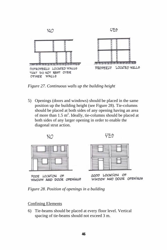
Figure 26. Symmetrical wall layout 4) The walls should be continuous up the building height (see
Figure 27).
46
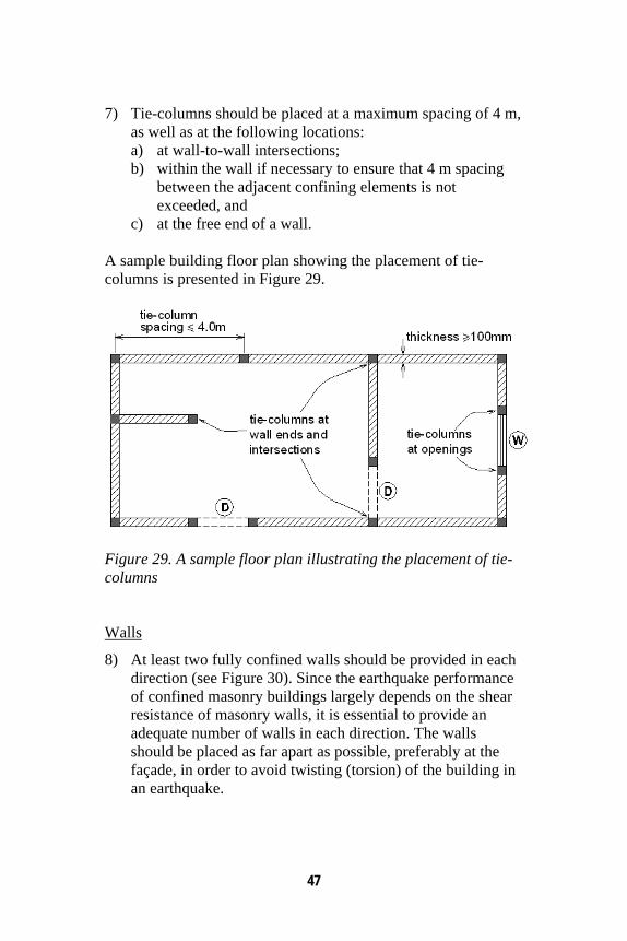
Figure 27. Continuous walls up the building height 5) Openings (doors and windows) should be placed in the same
position up the building height (see Figure 28). Tie-columns should be placed at both sides of any opening having an area of more than 1.5 m2. Ideally, tie-columns should be placed at both sides of any larger opening in order to enable the diagonal strut action.
Figure 28. Position of openings in a building Confining Elements
6) Tie-beams should be placed at every floor level. Vertical spacing of tie-beams should not exceed 3 m.
47
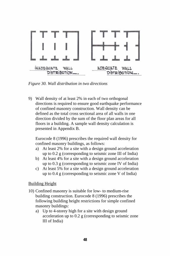
7) Tie-columns should be placed at a maximum spacing of 4 m, as well as at the following locations: a) at wall-to-wall intersections; b) within the wall if necessary to ensure that 4 m spacing
between the adjacent confining elements is not exceeded, and
c) at the free end of a wall. A sample building floor plan showing the placement of tie-columns is presented in Figure 29.
Figure 29. A sample floor plan illustrating the placement of tie-columns Walls
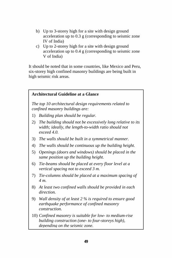
8) At least two fully confined walls should be provided in each direction (see Figure 30). Since the earthquake performance of confined masonry buildings largely depends on the shear resistance of masonry walls, it is essential to provide an adequate number of walls in each direction. The walls should be placed as far apart as possible, preferably at the façade, in order to avoid twisting (torsion) of the building in an earthquake.
48
Figure 30. Wall distribution in two directions 9) Wall density of at least 2% in each of two orthogonal
directions is required to ensure good earthquake performance of confined masonry construction. Wall density can be defined as the total cross sectional area of all walls in one direction divided by the sum of the floor plan areas for all floors in a building. A sample wall density calculation is presented in Appendix B.
Eurocode 8 (1996) prescribes the required wall density for confined masonry buildings, as follows: a) At least 2% for a site with a design ground acceleration
up to 0.2 g (corresponding to seismic zone III of India) b) At least 4% for a site with a design ground acceleration
up to 0.3 g (corresponding to seismic zone IV of India) c) At least 5% for a site with a design ground acceleration
up to 0.4 g (corresponding to seismic zone V of India) Building Height
10) Confined masonry is suitable for low- to medium-rise building construction. Eurocode 8 (1996) prescribes the following building height restrictions for simple confined masonry buildings: a) Up to 4-storey high for a site with design ground
acceleration up to 0.2 g (corresponding to seismic zone III of India)
49
b) Up to 3-storey high for a site with design ground acceleration up to 0.3 g (corresponding to seismic zone IV of India)
c) Up to 2-storey high for a site with design ground acceleration up to 0.4 g (corresponding to seismic zone V of India)
It should be noted that in some countries, like Mexico and Peru, six-storey high confined masonry buildings are being built in high seismic risk areas.
Architectural Guideline at a Glance The top 10 architectural design requirements related to confined masonry buildings are: 1) Building plan should be regular. 2) The building should not be excessively long relative to its
width; ideally, the length-to-width ratio should not exceed 4.0.
3) The walls should be built in a symmetrical manner. 4) The walls should be continuous up the building height. 5) Openings (doors and windows) should be placed in the
same position up the building height. 6) Tie-beams should be placed at every floor level at a
vertical spacing not to exceed 3 m. 7) Tie-columns should be placed at a maximum spacing of
4 m. 8) At least two confined walls should be provided in each
direction. 9) Wall density of at least 2 % is required to ensure good
earthquake performance of confined masonry construction.
10) Confined masonry is suitable for low- to medium-rise building construction (one- to four-storeys high), depending on the seismic zone.
50
7.3 Construction Guideline
Like any other type of building construction, it is essential to ensure good workmanship and the use of quality building materials when constructing a confined masonry building. Earthquake performance of a confined masonry building strongly depends on the quality of building materials, namely bricks or blocks, mortar, concrete, and reinforcing steel. This document does not prescribe minimum strength requirements for any building material. It is assumed that the minimum material quality requirements prescribed by pertinent standards related to RC and masonry construction are met. Since confined masonry involves both masonry and concrete construction, the importance of good practices related to the field execution of these two technologies cannot be overemphasized. The top 12 recommendations related to the construction of confined masonry buildings are outlined below. Tie-columns
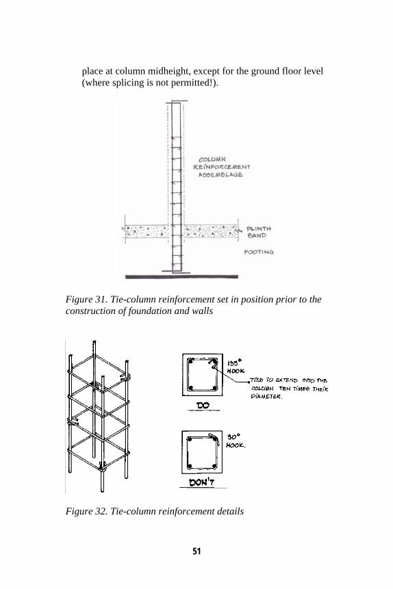
1) Reinforcement for the first storey tie-columns should be assembled before the foundation construction takes place, as shown in Figure 31. Reinforcement cages containing four vertical bars and cross-ties should be assembled and placed at the final column location (see Figure 32). Column ties should preferably have 135° hooks – the use of 90° hooks is not recommended.
2) Although the required tie-column reinforcement depends on
the number of storeys and the seismicity of the building site, most codes agree that four 10 mm diameter deformed bars (4 - 10 mm bars) are adequate for longitudinal reinforcement for a low-rise confined masonry building (up to two storeys high). At a minimum, 6 mm ties at 200 mm spacing (6 mm@200 mm) should be provided. It is recommended to use 6 mm ties at 100 mm spacing (6 mm@100 mm) in the column end-zones (top and bottom). Vertical bars should be lapped by a minimum 500 mm length. Splicing should take
51
place at column midheight, except for the ground floor level (where splicing is not permitted!).
Figure 31. Tie-column reinforcement set in position prior to the construction of foundation and walls
Figure 32. Tie-column reinforcement details
52
3) The tie-column cross-sectional dimensions should not be less than 100 mm by 100 mm. In general, the column width should be equal to the wall thickness.
Foundation and plinth construction
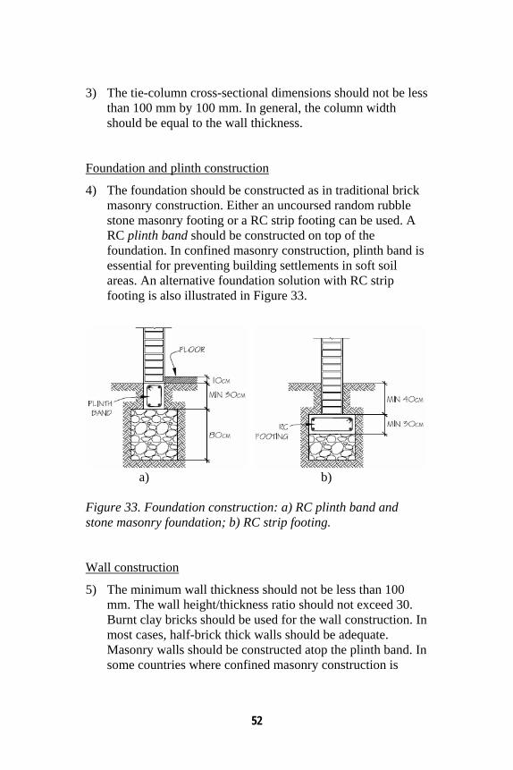
4) The foundation should be constructed as in traditional brick masonry construction. Either an uncoursed random rubble stone masonry footing or a RC strip footing can be used. A RC plinth band should be constructed on top of the foundation. In confined masonry construction, plinth band is essential for preventing building settlements in soft soil areas. An alternative foundation solution with RC strip footing is also illustrated in Figure 33.
a) b) Figure 33. Foundation construction: a) RC plinth band and stone masonry foundation; b) RC strip footing. Wall construction
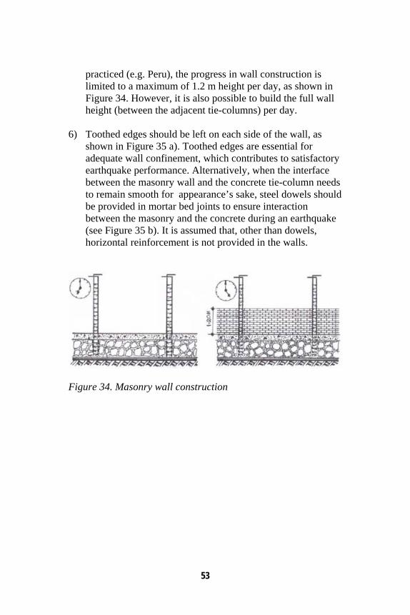
5) The minimum wall thickness should not be less than 100 mm. The wall height/thickness ratio should not exceed 30. Burnt clay bricks should be used for the wall construction. In most cases, half-brick thick walls should be adequate. Masonry walls should be constructed atop the plinth band. In some countries where confined masonry construction is
53
practiced (e.g. Peru), the progress in wall construction is limited to a maximum of 1.2 m height per day, as shown in Figure 34. However, it is also possible to build the full wall height (between the adjacent tie-columns) per day.
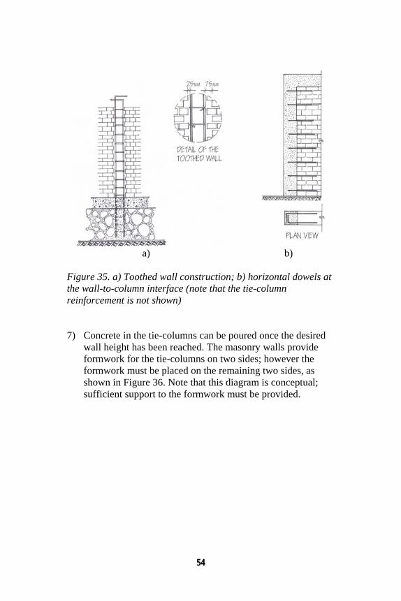
6) Toothed edges should be left on each side of the wall, as
shown in Figure 35 a). Toothed edges are essential for adequate wall confinement, which contributes to satisfactory earthquake performance. Alternatively, when the interface between the masonry wall and the concrete tie-column needs to remain smooth for appearance’s sake, steel dowels should be provided in mortar bed joints to ensure interaction between the masonry and the concrete during an earthquake (see Figure 35 b). It is assumed that, other than dowels, horizontal reinforcement is not provided in the walls.
Figure 34. Masonry wall construction
54
a) b) Figure 35. a) Toothed wall construction; b) horizontal dowels at the wall-to-column interface (note that the tie-column reinforcement is not shown) 7) Concrete in the tie-columns can be poured once the desired
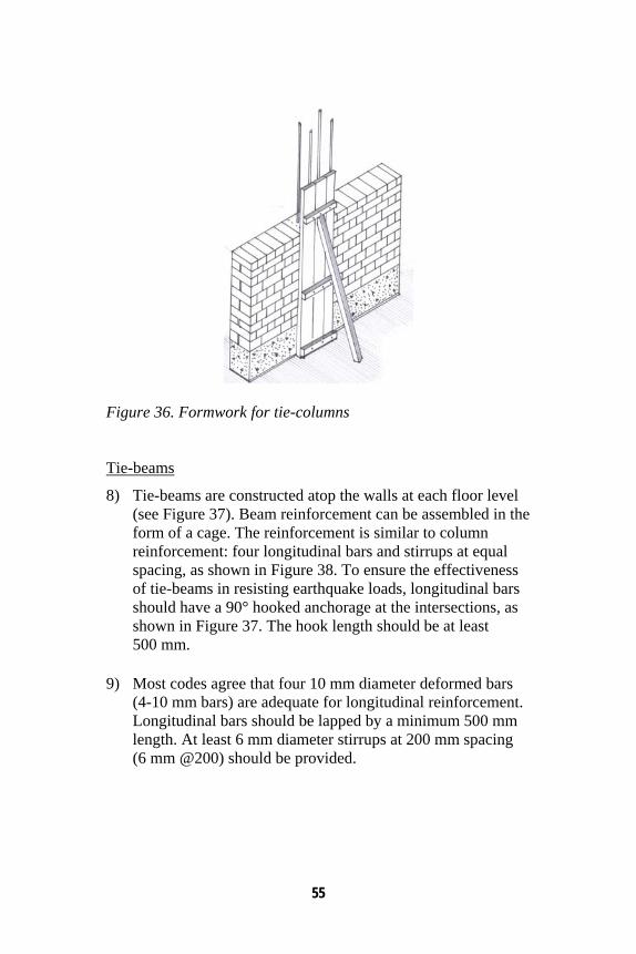
wall height has been reached. The masonry walls provide formwork for the tie-columns on two sides; however the formwork must be placed on the remaining two sides, as shown in Figure 36. Note that this diagram is conceptual; sufficient support to the formwork must be provided.
55
Figure 36. Formwork for tie-columns Tie-beams
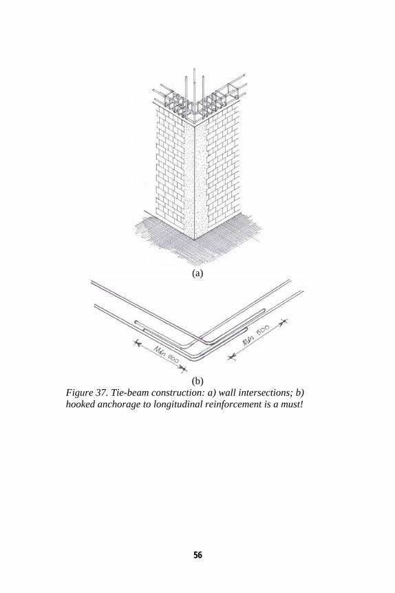
8) Tie-beams are constructed atop the walls at each floor level (see Figure 37). Beam reinforcement can be assembled in the form of a cage. The reinforcement is similar to column reinforcement: four longitudinal bars and stirrups at equal spacing, as shown in Figure 38. To ensure the effectiveness of tie-beams in resisting earthquake loads, longitudinal bars should have a 90° hooked anchorage at the intersections, as shown in Figure 37. The hook length should be at least 500 mm.
9) Most codes agree that four 10 mm diameter deformed bars
(4-10 mm bars) are adequate for longitudinal reinforcement. Longitudinal bars should be lapped by a minimum 500 mm length. At least 6 mm diameter stirrups at 200 mm spacing (6 mm @200) should be provided.
56
(a)
(b)
Figure 37. Tie-beam construction: a) wall intersections; b) hooked anchorage to longitudinal reinforcement is a must!
57
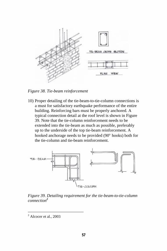
Figure 38. Tie-beam reinforcement 10) Proper detailing of the tie-beam-to-tie-column connections is
a must for satisfactory earthquake performance of the entire building. Reinforcing bars must be properly anchored. A typical connection detail at the roof level is shown in Figure 39. Note that the tie-column reinforcement needs to be extended into the tie-beam as much as possible, preferably up to the underside of the top tie-beam reinforcement. A hooked anchorage needs to be provided (90° hooks) both for the tie-column and tie-beam reinforcement.
Figure 39. Detailing requirement for the tie-beam-to-tie-column connection2 2 Alcocer et al., 2003
58
11) The tie-beam cross sectional dimensions should not be less than 100 mm by 100 mm. The beam width should be equal to the wall thickness. When the tie-beam is a part of the floor slab, the tie-beam reinforcement may be considered a part of the slab reinforcement. In that case, the slab thickness should be the same as the tie-beam depth.
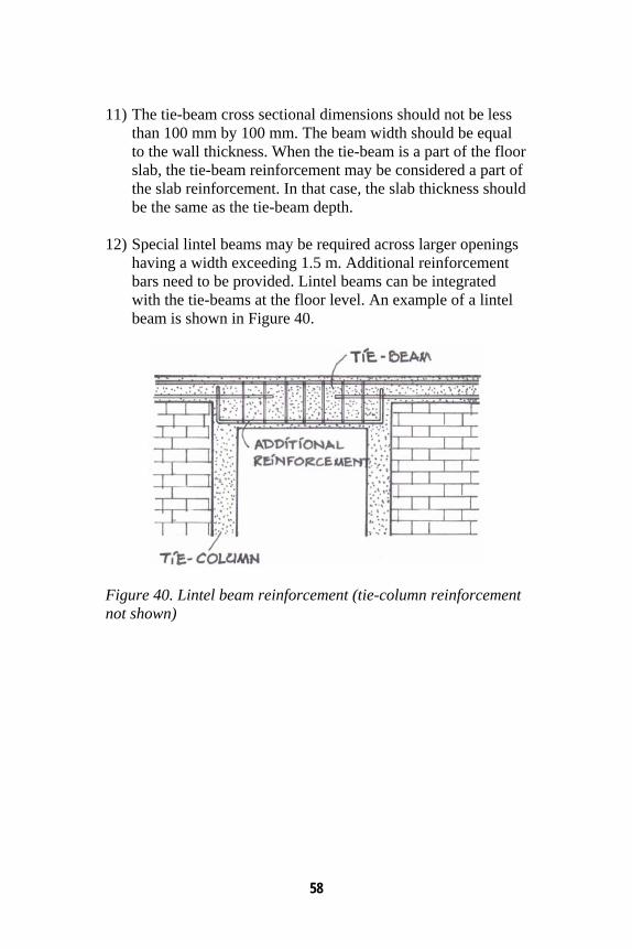
12) Special lintel beams may be required across larger openings
having a width exceeding 1.5 m. Additional reinforcement bars need to be provided. Lintel beams can be integrated with the tie-beams at the floor level. An example of a lintel beam is shown in Figure 40.
Figure 40. Lintel beam reinforcement (tie-column reinforcement not shown)
59
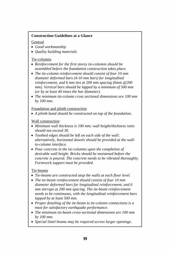
Construction Guidelines at a Glance
General • Good workmanship • Quality building materials Tie-columns • Reinforcement for the first storey tie-columns should be
assembled before the foundation construction takes place. • The tie-column reinforcement should consist of four 10 mm
diameter deformed bars (4-10 mm bars) for longitudinal reinforcement, and 6 mm ties at 200 mm spacing (6mm @200 mm). Vertical bars should be lapped by a minimum of 500 mm (or by at least 40 times the bar diameter).
• The minimum tie-column cross sectional dimensions are 100 mm by 100 mm.
Foundation and plinth construction • A plinth band should be constructed on top of the foundation. Wall construction • Minimum wall thickness is 100 mm; wall height/thickness ratio
should not exceed 30. • Toothed edges should be left on each side of the wall;
alternatively, horizontal dowels should be provided at the wall-to-column interface.
• Pour concrete in the tie-columns upon the completion of desirable wall height. Bricks should be moistened before the concrete is poured. The concrete needs to be vibrated thoroughly. Formwork support must be provided.
Tie-beams • Tie-beams are constructed atop the walls at each floor level. • The tie-beam reinforcement should consist of four 10 mm
diameter deformed bars for longitudinal reinforcement, and 6 mm stirrups at 200 mm spacing. The tie-beam reinforcement needs to be continuous, with the longitudinal reinforcement bars lapped by at least 500 mm.
• Proper detailing of the tie-beam to tie-column connections is a must for satisfactory earthquake performance.
• The minimum tie-beam cross-sectional dimensions are 100 mm by 100 mm.
• Special lintel beams may be required across larger openings.

60
61
8. Concluding Remarks Confined masonry buildings have performed well in several earthquakes worldwide. This construction practice is widely used in many countries and regions for the following reasons:
• It is based on traditional masonry construction practice; • It does not require highly qualified labour (as is the case
with RC frame construction); • Confined masonry technology falls in between that of
unreinforced masonry and RC frame construction, however due to its smaller member sizes and the larger amount of reinforcement it is more cost-effective than concrete construction;
• It has a broad range of applications - it can be used for single-family houses as well as for medium-rise apartment buildings.
The following disadvantages are associated with confined masonry construction:
• Confined masonry construction is more expensive than unreinforced masonry construction and requires somewhat higher level of labour skills, however its earthquake performance is significantly better than unreinforced masonry construction;
• It is characterized by lower strength and ductility when compared to properly built ductile RC frame construction and may require larger wall area when compared to RC frame construction with masonry infills.
Confined masonry construction has a great potential for saving lives and property in areas of high seismic risk in India. However, like any other construction practice, good earthquake performance is based on the following premises:
62
• Use of good quality materials, • Good quality concrete and masonry construction, and • Simple architectural design.
It is expected that this simple guideline featuring design and construction of confined masonry buildings will be useful to building professionals interested to learn more about this construction practice and engage in its design and construction.
63
References Alcocer, S.M. (2006). Personal Communication.
Alcocer, S., Arias, J.G., and Flores, L.E. (2004). Some Developments on Performance-Based Seismic Design of Masonry Structures. International Workshop on Performance-Based Seismic Design, Bled, Slovenia.
Alcocer, S., Arias, J.G., and Vazquez, A. (2004a). Response Assessment of Mexican Confined Masonry Structures Through Shaking Table Tests. Proceedings of the 13th World Conference on Earthquake Engineering, Vancouver, Canada, Paper No. 2130.
Alcocer, S.M., Cesin, J., Flores, L.E., Hemander, O., Meli, R., Tena, A., and Vasconcelos, D. (2003). The New Mexico City Building Code Requirements for Design and Construction of Masonry Structures. Proceedings of the 9th North American Masonry Conference, South Carolina, USA, No. 4B3.
Alcocer S.M., Aguilar G., Flores L., Bitrán D., Durán R., López O.A., Pacheco M.A., Reyes C., Uribe C.M., and Mendoza M.J. (2001). The Tehuacán Earthquake of June 15, 1999. Centro Nacional de Prevención de Desastres (SEGOB), Mexico City, Mexico, 198 pp (in Spanish).
Alcocer, S.M. and Klingner, R. (1994). Masonry Research in the Americas. Masonry in the Americas, ACI Publication SP-147, American Concrete Institute, Detroit, pp.127-169.
Aguilar G., and Alcocer S.M. (2001). Effect of Horizontal Reinforcement on the Behavior of Confined Masonry Walls Under Lateral Loads. Centro Nacional de Prevención de Desastres (SEGOB), Mexico City, Mexico, 181 pp (in Spanish).
Aguilar, G., Meli, R., Diaz, R., and Vazquez-del-Mercado, R. (1996). Influence of Horizontal Reinforcement on the
64
Behavior of Confined Masonry Walls. Proceedings of the 11th World Conference on Earthquake Engineering, Acapulco, Mexico, Paper No. 1380.
Aschheim, M., Flanagan, S., Harlander, J., Pitt, C., Alfaro, A., Rivas, C., and Rodriguez, M.E. (2006). Improving the Earthquake Resistance and Sustainability of Confined Masonry (Mixto) Dwellings in El Salvador. Proceedings of the 8th U.S. National Conference on Earthquake Engineering, San Francisco, USA, Paper No. 1462.
Blondet, M. (2005). Construction and Maintenance of Masonry Houses – For Masons and Craftsmen. Pontificia Universidad Catolica del Peru, Lima, Peru (http://www.world-housing.net/)
Boen, T. (2006). Structural Damage in the March 2005 Nias-Simeulue Earthquake. Special Issue on the Great Sumatra Earthquakes and Indian Ocean Tsunamis of 26 December 2004 and 28 March 2005, Earthquake Spectra, Vol. 22, No S3, pp. S419-S434.
Boen, T. (2005). Sumatra Earthquake 26 Dec 2004. Earthquake Engineering Research Institute, Oakland, California (www.eeri.org)
Casabonne, C. (1994). General Description of Systems and Construction Practices. Masonry in the Americas, ACI Publication SP-147, American Concrete Institute, Detroit, pp.21-55.
Casabonne, C. (2000). Masonry in the Seismic Areas of the Americas, Recent Investigation and Development. Progress in Structural Engineering and Materials, John Wiley &Sons Ltd., Volume 2, pp.319-327.
City University of London (2005). Low-Rise Residential Construction Detailing to Resist Earthquakes. City University of London and Pell Frichmann (www.staff.city.ac.uk/earthquakes/Repairstrengthening/index.php)
Dowling, D.M. (2004). Adobe Housing Reconstruction after the 2001 El Salvador Earthquakes. Lessons Learned Over Time - Learning From Earthquakes Series, Volume 5, Earthquake
65
Engineering Research Institute (EERI), Oakland, California, 69 pp.
EERI (2007). The Pisco, Peru Earthquake of August 15, 2007. EERI Special Earthquake Report. Newsletter. Earthquake Engineering Research Institute, Oakland, California, October 2007.
EERI (2007a). Observations from the Southern Sumatra Earthquakes of September 12-13, 2007. EERI Special Earthquake Report. Newsletter. Earthquake Engineering Research Institute, Oakland, California, November 2007.
EERI (2006a). Special Issue on the Great Sumatra Earthquakes and Indian Ocean Tsunamis of 26 December 2004 and 28 March 2005. Earthquake Spectra, Vol. 22, No S3, June 2006.
EERI (2006b). The Tecomán, México Earthquake January 21, 2003. An EERI and SMIS Learning from Earthquakes Reconnaissance Report, Technical Editors S.M. Alcocer and R.E. Klingner, Earthquake Engineering Research Institute, Oakland, California, March 2006.
EERI (2005). The Northern Sumatra Earthquake of March 28, 2005. EERI Special Earthquake Report. Newsletter. Earthquake Engineering Research Institute, California, August 2005.
EERI (2001). Preliminary Observations on the El Salvador Earthquakes of January 13 and February 13, 2003. EERI Special Earthquake Report. Newsletter. Earthquake Engineering Research Institute, California, July 2001.
EERI (2001a). Preliminary Reports and Annotated Images from the El Salvador Earthquakes of January 13 and February 13, 2001. Photos by Manuel Alfredo Lopez Menjivar, a CD-Rom publication, Earthquake Engineering Research Institute, California.
EERI/IAEE (2000). World Housing Encyclopedia (www.world-housing.net). Earthquake Engineering Research Institute and the International Association for Earthquake Engineering.
66
EERI (2000a). El Quindio, Colombia Earthquake, January 25, 1999: Reconnaissance Report. An EERI Learning from Earthquakes Project. Earthquake Engineering Research Institute, California.
EERI (1999). The Tehuacan, Mexico, Earthquake of June 15, 1999. EERI Special Earthquake Report. Newsletter. Earthquake Engineering Research Institute, California, September 1999.
Eurocode 6 (1995). Design of Masonry Structures. Part 1-1: General Rules for Buildings. Rules for Reinforced and Unreinforced Masonry. ENV1996-1-1, CEN, Brussels.
Eurocode 8 (1996). Design Procedures for Earthquake Resistance of Structures. Part 1-3: General Rules – Specific Rules for Various Materials and Elements. ENV1998-1-3, CEN, Brussels.
Garcia, H.J. (2006). Personal Communication.
Garcia, L.E., and Yamin, L.E. (1994). A Review of Masonry Construction in Columbia. Masonry in the Americas, ACI Publication SP-147, American Concrete Institute, Detroit, pp. 283-305.
Gallegos, H. (1994). Masonry in Peru. Masonry in the Americas, ACI Publication SP-147, American Concrete Institute, Detroit, pp.307-331.
GSHAP (1999). Global Seismic Hazard Assessment Program, International Lithosphere Program (www.seismo.ethz.ch/GSHAP/global/).
Hashemi, B.H., Alemi, F., and Ashtiany, G. (2003). Confined Brick Masonry Building with Concrete Tie-Columns and Beams. Iran, Report 27, World Housing Encyclopedia, Earthquake Engineering Research Institute (www.world-housing.net)
Instituto Nacional de Normalizacion (1997). Albañilería Confinada-requisitos para el diseño y cálculo (NCh2123.Of97). Instituto Nacional de Normalizacion, Santiago, Chile (in Spanish).
67
Lutman, M., and Tomazevic, M. (2003). Confined Brick Masonry House. Slovenia, Report 88, World Housing Encyclopedia, Earthquake Engineering Research Institute (www.world-housing.net)
Meisl, C.S., Safaie, S., Elwood, K.J., Gupta, R., and Kowsari, R. (2006). Housing Reconstruction in Northern Sumatra after the December 2004 Great Sumatra Earthquake and Tsunami. Special Issue on the Great Sumatra Earthquakes and Indian Ocean Tsunamis of 26 December 2004 and 28 March 2005, Earthquake Spectra, Vol. 22, No S3, pp. S777-S802.
Meli, R. and Alcocer, S. (2004). Implementation of Structural Earthquake-Disaster Mitigation Programs in Developing Countries. Natural Hazards Review, ASCE,Vol.5, No.1, pp. 29-39.
Meli, R. (1994). Structural Design of Masonry Buildings: the Mexican Practice. Masonry in the Americas, ACI Publication SP-147, American Concrete Institute, Detroit, pp. 239-262.
Moroni, O., Gomez, C., and Astroza, M. (2003). Confined Block Masonry Building. Chile, Report 7, World Housing Encyclopedia, Earthquake Engineering Research Institute (www.world-housing.net)
Moroni, M.O., Astroza, M., and Acevedo, C. (2004). Performance and Seismic Vulnerability of Masonry Housing Types Used in Chile. Journal of Performance of Constructed Facilities, ASCE, Vol.18, No.3, pp.173-179.
Murty, C.V.R, Brzev, S., Faison, H., Comartin, C.D., and Irfanoglu, A. (2006). At Risk: The Seismic Performance of Reinforced Concrete Frame Buildings with Masonry Infill Walls. Earthquake Engineering Research Institute, Publication No. WHE-2006-03, First Edition, 70 pp.
Murty, C.V.R. (2005). Earthquake Tips – Learning Earthquake Design and Construction. Indian Institute of Technology Kanpur and Building Materials and Technology Promotion Council, India.
68
Murty, C.V.R., and Jain, S.K. (2000). Beneficial Influence of Masonry Infill Walls on Seismic Performance of RC Frame Buildings. Proceedings of the 12th World Conference on Earthquake Engineering, Auckland, New Zealand, Paper No. 1790.
Nesheli, K.N. (2004). Structural Damage to Buildings Due to Bam Earthquake of December 26, 2003, Iran. ICUS/INCEDE Newsletter, International Center for Urban Safety Engineering, Institute of Industrial Science, the University of Tokyo, Vol.3, No.4.
NTC-M 2002. “Normas Técnicas Complementarias para Diseño y Construcción de Estructuras de Mampostería” (Technical Norms for Design and Construction of Masonry Structures), Mexico D.F. (in Spanish).
NTC-M 2004. “Normas Técnicas Complementarias para Diseño y Construcción de Estructuras de Mampostería” (Technical Norms for Design and Construction of Masonry Structures), Mexico D.F. (in Spanish).
NTC-S 2004. “Normas Técnicas Complementarias para Diseño por Sismo” (Complimentary Technical Norms for Seismic Design), Mexico D.F. (in Spanish).
Paulson, C. and Hultengren, L. (2001). El Salvador Earthquake of January 13, 2001. Slide Presentation, Preliminary Reports and Annotated Images from the El Salvador Earthquakes of January 13 and February 13, 2001, a CD-Rom publication, Earthquake Engineering Research Institute, Oakland, California.
Rodriguez, V.I., Yacante, M.I., Reiloba, S. (2003). Confined Block Masonry House. Argentina, Report 1, World Housing Encyclopedia, Earthquake Engineering Research Institute (www.world-housing.net)
Schultz, A. E. (1994). Performance of Masonry Structures During Extreme Lateral Loading Events. Masonry in the Americas, ACI Publication SP-147, American Concrete Institute, Detroit, pp.21-55.
69
Tomazevic, M. and Klemenc, I. (1997). Seismic Behaviour of Confined Masonry Walls. Earthquake Engineering and Structural Dynamics, Vol. 26, pp.1059-1071.
Tomazevic, M. (1999). “Earthquake-Resistant Design of Masonry Buildings”. Imperial College Press, London, U.K.
Yanez,F., Astroza, M., Holmberg,A., and Ogaz,O. (2004). Behavior of Confined Masonry Shear Walls with Large Openings. Proceedings of the 13th World Conference on Earthquake Engineering, Vancouver, Canada, Paper No. 3438.
Yang, W., and Jian, Z. (1988). Functions of Tied Concrete Columns in Brick Walls. Proceedings of the Ninth World Conference on Earthquake Engineering, Tokyo, Japan, Vol.6, pp.139-144.
Yoshimura, K., Kikuchi, K., Kuroki, M., Nonaka, H., Kim, K.T., Wangdi, R., and Oshikata, A. (2004). Experimental Study For Developing Higher Seismic Performance of Brick Masonry Walls. Proceedings of the 13th World Conference on Earthquake Engineering, Vancouver, Canada, Paper No. 1597.
Zahrai S.M. and Heidarzadeh, M. (2004). Seismic Performance of Existing Buildings During the 2003 Bam Earthquake. Proceedings of the 13th World Conference on Earthquake Engineering, Vancouver, Canada, Paper No. 1715.

70
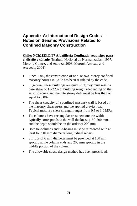
71
Appendix A: International Design Codes – Notes on Seismic Provisions Related to Confined Masonry Construction Chile: NCh2123.Of97 Albañilería Confinada-requisitos para el diseño y cálculo (Instituto Nacional de Normalizacian, 1997; Moroni, Gomez, and Astroza, 2003; Moroni, Astroza, and Acevedo, 2004) • Since 1949, the construction of one- or two- storey confined
masonry houses in Chile has been regulated by the code. • In general, these buildings are quite stiff, they must resist a
base shear of 10-22% of building weight (depending on the seismic zone), and the interstorey drift must be less than or equal to 0.002.
• The shear capacity of a confined masonry wall is based on the masonry shear stress and the applied gravity load. Typical masonry shear strength ranges from 0.5 to 1.0 MPa.
• Tie columns have rectangular cross section; the width typically corresponds to the wall thickness (150-200 mm) and the depth should be on the order of 200 mm.
• Both tie-columns and tie-beams must be reinforced with at least four 10 mm diameter longitudinal rebars.
• Stirrups of 6 mm diameter must be provided at 100 mm spacing at the column ends and 200 mm spacing in the middle portion of the column.
• The allowable stress design method has been prescribed.
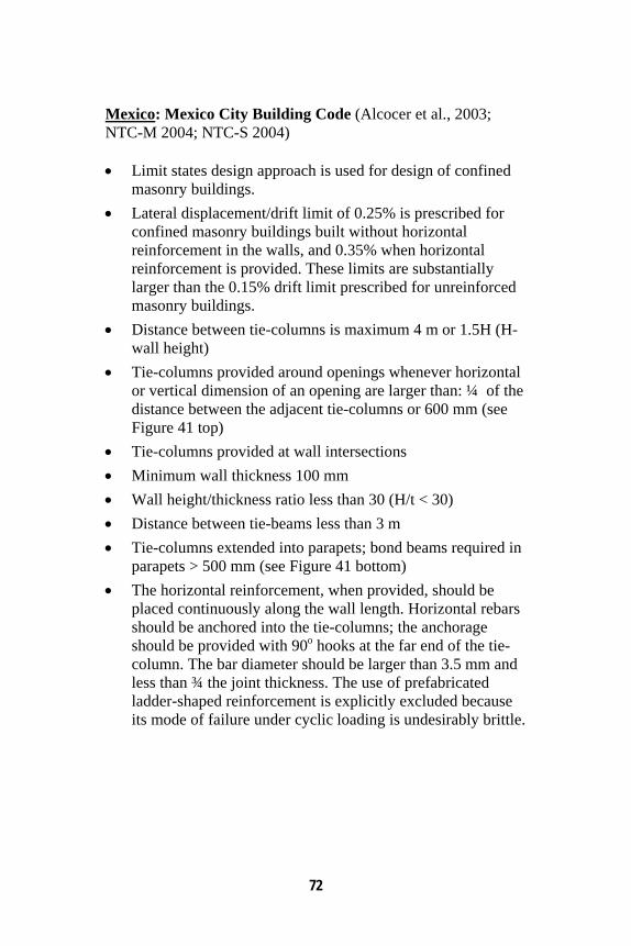
72
Mexico: Mexico City Building Code (Alcocer et al., 2003; NTC-M 2004; NTC-S 2004) • Limit states design approach is used for design of confined
masonry buildings. • Lateral displacement/drift limit of 0.25% is prescribed for
confined masonry buildings built without horizontal reinforcement in the walls, and 0.35% when horizontal reinforcement is provided. These limits are substantially larger than the 0.15% drift limit prescribed for unreinforced masonry buildings.
• Distance between tie-columns is maximum 4 m or 1.5H (H- wall height)
• Tie-columns provided around openings whenever horizontal or vertical dimension of an opening are larger than: ¼ of the distance between the adjacent tie-columns or 600 mm (see Figure 41 top)
• Tie-columns provided at wall intersections • Minimum wall thickness 100 mm • Wall height/thickness ratio less than 30 (H/t < 30) • Distance between tie-beams less than 3 m • Tie-columns extended into parapets; bond beams required in
parapets > 500 mm (see Figure 41 bottom) • The horizontal reinforcement, when provided, should be
placed continuously along the wall length. Horizontal rebars should be anchored into the tie-columns; the anchorage should be provided with 90o hooks at the far end of the tie-column. The bar diameter should be larger than 3.5 mm and less than ¾ the joint thickness. The use of prefabricated ladder-shaped reinforcement is explicitly excluded because its mode of failure under cyclic loading is undesirably brittle.
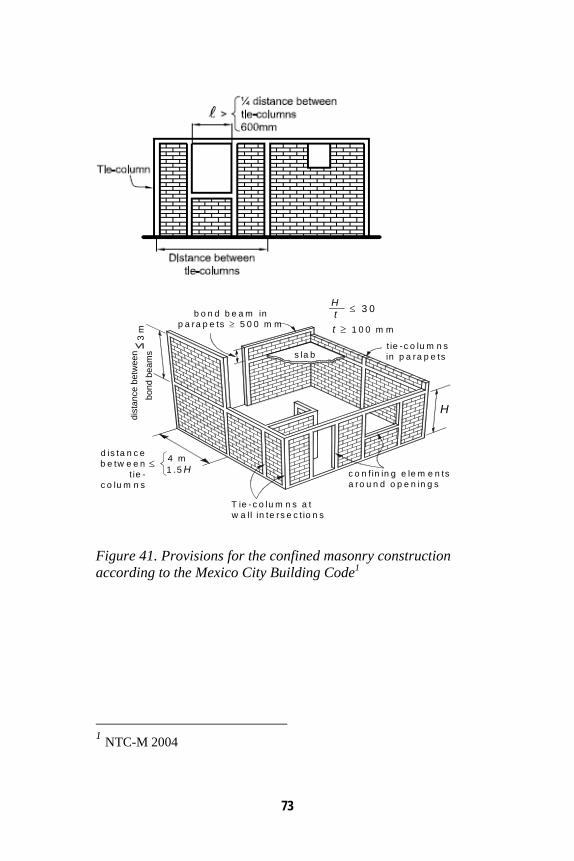
73
T ie -c o lu m n s a tw a l l in te rs e c t io n s
s la b
d is ta n c eb e tw e e n
t ie -c o lu m n s
4 m1 .5 H≤
dist
ance
be t
wee
nbo
nd b
eam
s
b o n d b e a m inp a ra p e ts ≥ 5 0 0 m m
3 m
c o n f in in g e le m e n tsa ro u n d o p e n in g s
t ie -c o lu m n sin p a ra p e ts
H
t ≥ 1 0 0 m m
Ht ≤ 3 0
Figure 41. Provisions for the confined masonry construction according to the Mexico City Building Code1
1 NTC-M 2004
74
Eurocode 6 (1995)/Eurocode 8 (1996) • The effect of confining elements (tie-columns and tie-beams)
should be disregarded in seismic design of confined masonry buildings. Seismic resistance should be based on masonry contribution only (Cl.4.9.(4), Eurocode 6 Section 1-1). This provision is considered to be conservative (Tomazevic, 1999). Experimental research studies have confirmed the contribution of confining elements to earthquake resistance of confined masonry structures, as discussed earlier in this document.
• Confined masonry should be constructed with horizontal RC or reinforced masonry members provided at every floor level and with vertical reinforced concrete or reinforced masonry members (Cl.5.2.9.(2), Eurocode 6 Section 1-1).
• Vertical members should be provided at every wall intersection and at both sides of every opening having an area of more than 1.5 m2. Additional reinforced concrete or reinforced masonry members may be required in the wall so that the maximum spacing, both horizontally and vertically, is 4 m (Cl.5.2.9.(2), Eurocode 6 Section 1-1).
• In order to obtain an effective bond between the confining elements and the masonry, the concrete of the confining elements shall be cast after the masonry has been built (Cl.5.5.3.(2), Eurocode 8 Section 1-3).
• The cross section of both horizontal and vertical confining elements shall not be less than 150 x 150 mm (Cl.5.5.3.(3), Eurocode 8 Section 1-3).
• Vertical confining elements shall be placed (Cl.5.5.3.(4), Eurocode 8 Section 1-3)
o at both sides of any opening with an area of more than 1.5 m2;
o at every wall intersection; o within the wall if necessary in order not to exceed a
spacing of 4 m between the confining members.
75
Horizontal confining elements shall be placed in the plane of the wall at every floor level and in any case spaced not more than 4 m (Cl.5.5.3.(5), Eurocode 8 Section 1-3). The area of reinforcement in each vertical and horizontal confining element shall not be less than 240 mm2. The reinforcement shall be contained by regularly spaced stirrups (Cl.5.5.3.(6), Eurocode 8 Section 1-3), see Figure 42. • The number of storeys above ground should not exceed
(Cl.5.7.2.(1), Eurocode 8 Section 1-3): o Four storeys (design ground acceleration < 0.2 g) o Three storeys (design ground acceleration < 0.3 g) o Two storeys (design ground acceleration > 0.3 g)
• At every floor the horizontal wall cross section given as a percentage of the total floor area above the level considered, is not less than (Cl.5.7.2.(7), Eurocode 8 Section 1-3):
o 2% (design ground acceleration < 0.2 g) o 4 % (design ground acceleration < 0.3 g) o 5 % (design ground acceleration > 0.3 g)
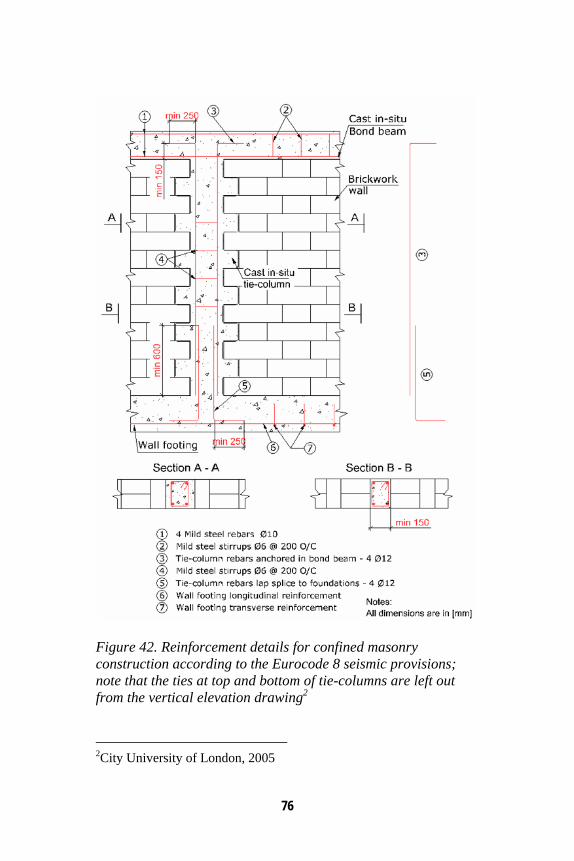
76
Figure 42. Reinforcement details for confined masonry construction according to the Eurocode 8 seismic provisions; note that the ties at top and bottom of tie-columns are left out from the vertical elevation drawing2
2City University of London, 2005
77
Iran: Iranian Code of Practice for Seismic Resistant Design of Buildings (Standard 2800) (Nesheli, 2004) • Since 1987, the Iranian Code of Practice for Seismic
Resistant Design of Buildings (Standard 2800) addresses confined masonry construction. The latest edition of this code was issued in 1999.
• Confining elements must be constructed in structural walls of masonry buildings (one- or two-storey high), irrespective of whether they are constructed with blocks, cement, or stone.
• Tie-columns should be properly connected at all intersection points to tie-beams.
• The distance between adjacent tie-columns should be limited to 5 m.
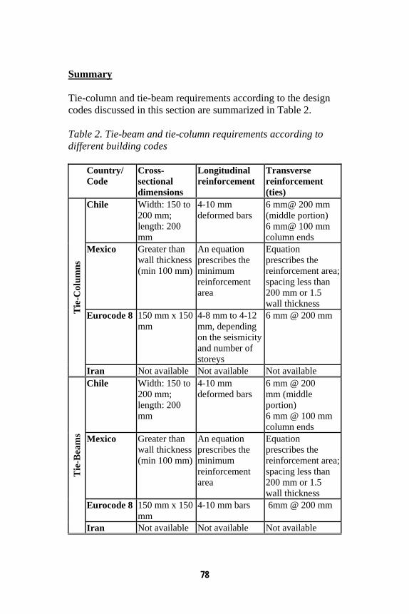
78
Summary Tie-column and tie-beam requirements according to the design codes discussed in this section are summarized in Table 2. Table 2. Tie-beam and tie-column requirements according to different building codes Country/
Code Cross-sectional dimensions
Longitudinal reinforcement
Transverse reinforcement (ties)
Chile Width: 150 to 200 mm; length: 200 mm
4-10 mm deformed bars
6 mm@ 200 mm (middle portion) 6 mm@ 100 mm column ends
Mexico Greater than wall thickness (min 100 mm)
An equation prescribes the minimum reinforcement area
Equation prescribes the reinforcement area; spacing less than 200 mm or 1.5 wall thickness
Eurocode 8 150 mm x 150 mm
4-8 mm to 4-12 mm, depending on the seismicity and number of storeys
6 mm @ 200 mm Tie
-Col
umns
Iran Not available Not available Not available Chile Width: 150 to
200 mm; length: 200 mm
4-10 mm deformed bars
6 mm @ 200 mm (middle portion) 6 mm @ 100 mm column ends
Mexico Greater than wall thickness (min 100 mm)
An equation prescribes the minimum reinforcement area
Equation prescribes the reinforcement area; spacing less than 200 mm or 1.5 wall thickness
Eurocode 8 150 mm x 150 mm
4-10 mm bars 6mm @ 200 mm
Tie
-Bea
ms
Iran Not available Not available Not available
79
Appendix B: An Example Illustrating Wall Density Calculation Wall density can be defined as the total cross-sectional area of all walls in one direction divided by the total floor area, that is,
WALL DENSITY = WALL AREA / TOTAL FLOOR AREA where WALL AREA = cross-sectional area of all walls in one direction, that is, the product of the wall length and thickness (it is not necessary to deduct the area of tie-columns) TOTAL FLOOR AREA = sum of floor areas for all floors in the building
Example: Consider a two-storey confined masonry building located in the seismic zone III of India. The walls are built of burnt clay bricks and the wall thickness is 110 mm (half-brick thick wall). The size of tie-columns matches the wall size, that is, the cross-sectional dimensions are 110 mm by 110 mm. A typical floor plan is shown in Figure 43. Confirm that the wall density is adequate for the seismic zone III according to the Guideline.
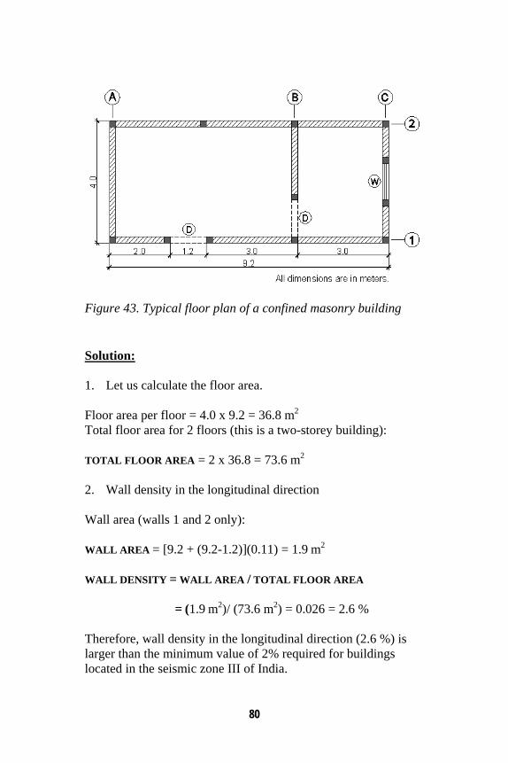
80
Figure 43. Typical floor plan of a confined masonry building Solution: 1. Let us calculate the floor area. Floor area per floor = 4.0 x 9.2 = 36.8 m2
Total floor area for 2 floors (this is a two-storey building): TOTAL FLOOR AREA = 2 x 36.8 = 73.6 m2 2. Wall density in the longitudinal direction Wall area (walls 1 and 2 only): WALL AREA = [9.2 + (9.2-1.2)](0.11) = 1.9 m2
WALL DENSITY = WALL AREA / TOTAL FLOOR AREA
= (1.9 m2)/ (73.6 m2) = 0.026 = 2.6 % Therefore, wall density in the longitudinal direction (2.6 %) is larger than the minimum value of 2% required for buildings located in the seismic zone III of India.
81
3. Wall density in the transverse direction Wall area (walls A, B, and C): WALL AREA = [4.0 + (4.0-1.2) + (4.0-1.2)](0.11) = 1.1 m2
WALL DENSITY = WALL AREA / TOTAL FLOOR AREA
= (1.1 m2)/ (73.6 m2) = 0.015 = 1.5% Therefore, wall density in the longitudinal direction (1.5%) is smaller than the minimum value of 2% required for buildings located in seismic zone III of India. In order to satisfy the wall density requirement, wall thickness can be increased in the transverse direction only. Instead of using the half-brick thick walls, one-brick thick walls can be used. As a result, wall thickness will be increased from 110 mm to 220 mm, that is, by 100%. Wall density is directly proportional to the wall thickness and so its value will increase to 3.0%. The revised wall density value meets the 2% limit recommended by the Guideline.

82

NATIONAL INFORMATION CENTER OF EARTHQUAKE ENGINEERING
MISSION The National Information Center of Earthquake Engineering (NICEE) at Indian Institute of Technology Kanpur maintains and disseminates information resources on Earthquake Engineering. It undertakes community outreach activities aimed at mitigation of earthquake disasters. NICEE’s target audience includes professionals, academics and all others with an interest in and concern for seismic safety.
SPONSORS NICEE receives no budget from any sources and operates entirely on the interest income of its endowment, sponsorships, publication sales, and the donations. One-time grants from the following organizations made it possible to launch the operations of NICEE:
Housing and Urban Development Corporation, New Delhi Department of Telecom, New Delhi Railway Board, New Delhi Ministry of Agriculture, Government of India, New Delhi Department of Atomic Energy, Mumbai
List of donors may be viewed at www.nicee.org/Giving.php
All donations to NICEE from within India and USA are 100% tax deductible.
For more information, please contact:
Prof. Sudhir K. Jain Coordinator, NICEE Indian Institute of Technology Kanpur Kanpur 208016 (INDIA) Phone: 91-512-259 7866; Fax: 91-512-259 7794 Email: [email protected]; Web: www.nicee.org
To receive free monthly electronic newsletter, please register at: www.nicee.org
NICEE Publications and Products Publications
Earthquake Engineering Practice (A Quarterly Periodical) IITK-BMTPC Earthquake Tips by C. V. R. Murty Design of Foundations in Seismic Areas: Principles and Applications by S. Bhattacharya (Editor) Seismic Conceptual Design of Buildings - Basic principles for engineers, architects, building owners, and authorities by H. Bachmann At Risk: Seismic Performance of RC Frame Buildings with Masonry Infill Walls by C. V. R. Murty et al. Earthquake Dynamics of Structures, A Primer by A. K. Chopra Earthquake Design Criteria by G. W. Housner and P. C. Jennings Guidelines for Earthquake Resistant Non-Engineered Construction (English) by IAEE Guidelines for Earthquake Resistant Non-Engineered Construction (Hindi) by IAEE Keeping Schools Safe in Earthquakes by OECD Fundamentals of Seismic Protection for Bridges by M. Yashinsky and M. J. Karshenas Seismic Hazard and Risk Analysis by R. K. McGuire Reconnaissance Report of Sikkim Earthquake of 14 February 2006 by H. B. Kaushik et al. Earthquake Rebuilding in Gujarat, India by C.V.R. Murty et al. The Great Sumatra Earthquake and Andaman Ocean Tsunami of December 26 2004 by S. K. Jain et al. Annotated Images from the Bhuj, India Earthquake of January 26, 2001 (CD) by EERI Bhuj, India Republic Day January 26, 2001 Earthquake Reconnaissance Report (CD) by S. K. Jain et al. (editor)
Audio-Video Lectures on CD Concept of Earthquake Resistant Design by S. K. Jain Seismic Retrofit Techniques for Masonry Buildings - An Overview by S. N. Brzev Buildings on Rollers-Use of Passive Control Devices for Seismic Protection of Structures by S.N. Brzev Seismic Design & Retrofit of Nonstructural Building Components by S. N. Brzev Building Performance in Boumerdes (Algeria) Earthquake of 21 May 2003 by S. N. Brzev The History of Earthquake Engineering from an International Perspective by R. Reitherman Structure & Architecture, Architecture & Earthquakes by A. W. Charleson Seismic Hazard and Its Quantification by Late B. A. Bolt Earthquake Resistant Design of Steel Buildings in the US by J. E. Rodgers
PowerPoint Slides on CD E-course: Indian Seismic Code IS: 1893-2002(part-I) by S. K. Jain E-course: Seismic Design of Liquid Storage Tanks by S. K. Jain and O. R. Jaiswal
CD and Hard Copy Architectural Teaching Resource Material on Earthquake Design Concepts for Teachers of Architecture Colleges by C. V. R. Murty and A. W. Charleson Manual for Experimental Studies in Earthquake Engineering Education by C. S. Manohar and S. Venkatesha
IITK-GSDMA Guidelines Guidelines for Seismic Design of Liquid Storage Tanks Guidelines for Structural Use of Reinforced Masonry Guidelines for Seismic Evaluation and Strengthening of Existing Buildings Guidelines for Seismic Design of Dams and Embankments Guidelines for Seismic Design of Buried Pipelines Guidelines on Measures to Mitigate Effects of Terrorist Attacks on Buildings

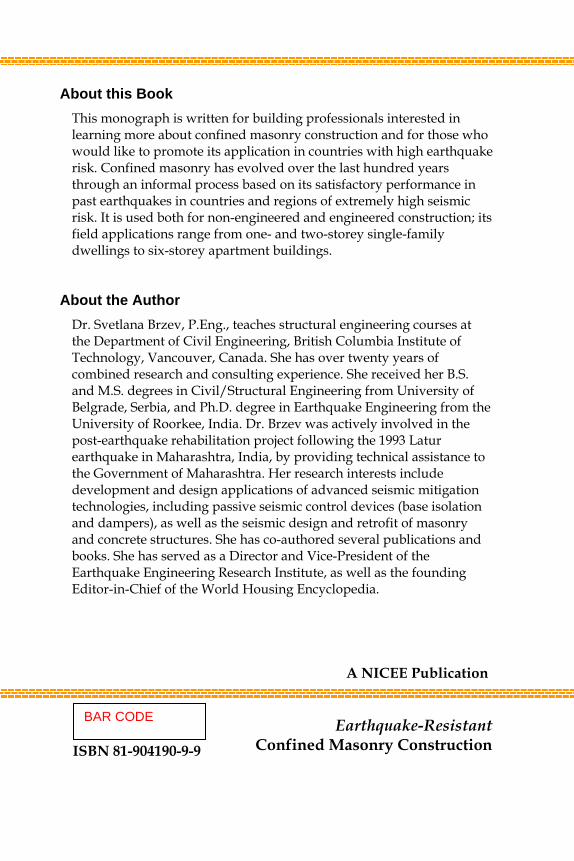
About this Book This monograph is written for building professionals interested in learning more about confined masonry construction and for those who would like to promote its application in countries with high earthquake risk. Confined masonry has evolved over the last hundred years through an informal process based on its satisfactory performance in past earthquakes in countries and regions of extremely high seismic risk. It is used both for non-engineered and engineered construction; its field applications range from one- and two-storey single-family dwellings to six-storey apartment buildings.
About the Author
Dr. Svetlana Brzev, P.Eng., teaches structural engineering courses at the Department of Civil Engineering, British Columbia Institute of Technology, Vancouver, Canada. She has over twenty years of combined research and consulting experience. She received her B.S. and M.S. degrees in Civil/Structural Engineering from University of Belgrade, Serbia, and Ph.D. degree in Earthquake Engineering from the University of Roorkee, India. Dr. Brzev was actively involved in the post-earthquake rehabilitation project following the 1993 Latur earthquake in Maharashtra, India, by providing technical assistance to the Government of Maharashtra. Her research interests include development and design applications of advanced seismic mitigation technologies, including passive seismic control devices (base isolation and dampers), as well as the seismic design and retrofit of masonry and concrete structures. She has co-authored several publications and books. She has served as a Director and Vice-President of the Earthquake Engineering Research Institute, as well as the founding Editor-in-Chief of the World Housing Encyclopedia.
A NICEE Publication
Earthquake-Resistant Confined Masonry Construction
ISBN 81-904190-9-9
BAR CODE
Earthquake-Resistant C
onfined Masonry C
onstruction - S. Brzev - N
ICEE