earthquake reinforcement using jet grouting for a factory in … papers/kawamura_735.00.pdf · 6th...
TRANSCRIPT

6th International Conference on Earthquake Geotechnical Engineering 1-4 November 2015 Christchurch, New Zealand
Earthquake Reinforcement Using Jet Grouting for a Factory in
Operation
J. Kawamura1
ABSTRACT This paper introduces the application of jet grouting for soil improvement to reinforce the foundations of a factory building located in central Japan that may be impacted by the Great Nankai or East Nankai earthquakes, the magnitudes of which are estimated to be 8.0. The operational constraints given by the client required jet grouting to be carried out from the inside of the building in clean conditions, and without relocating any facilities so as to not interfere with the operation of the factory. In order to overcome such difficulties, CGC developed small jet grouting machines that can fit into narrow spaces, and succeeded in making soil improvement columns 2.5m in diameter and 8.0m in the length from the ground level as an integrated part of the building structure. This paper reports that jet grouting not only succeeded in making the columns in narrow and cramped spaces inside the building, but also satisfied the strict standards that a public agency (the Building Center of Japan) requires.
Introduction This paper is a report on a construction case to reinforce the foundations of a food factory against large-scale earthquakes. Figure 1 is area where damage is anticipated by large-scale earthquake. To make sure the factory would be capable of operating after an earthquake, we implemented countermeasures to earthquakes for the foundations of the structure. Soil improvement was chosen as a reinforcement method. The purpose of soil improvement is to help bear the horizontal load on the existing piles of the factory when an earthquake occurs. The existing piles bear the vertical load of structure. The main requirements by client are the following:
1. Don’t stop the 24hour operation of the factory.
2. Don’t relocate any facilities so as to not interface with the operation of the factory. Jet grouting was adopted for construction under these conditions. In the past, jet grouting was used as a temporary construction material, but this is a case for permanent foundations for an operating factory, so high-level of quality control was carried out. Specifically, we confirmed three items: recovery rate of core sampling, unconfined compressive strength, and adhesion to slabs, to ensure the quality requirements. Figure 2 is location of the factory and view of construction site.
Outline of Construction The reinforcement of foundations against earthquakes was undertaken for a food factory that operates 24 hours a day. The factory is about 500m in length and, 100m in width. About 60 facilities operate on the large-scale premises. In order to keep the operation of the factory intact, 1Design Department, Chemical Grouting, Tokyo, Japan, [email protected]

and without relocating any facilities, construction was undertaken in the narrow spaces around pipes and facilities inside the factory. JETCRETE, our proprietary jet grouting method, was proposed for the soil improvement. JETCRETE can construct any diameter and any strength of soil improvement in narrow spaces. The soil improvement columns with 2.5m in diameter were chosen in considering the soil conditions and the operational constrains with pipes in the factory. Figure 3 and Figure 4 indicate schema of soil improvement.
Figure 1. Area where heavy damage is anticipated (Central conference of disaster prevention (in Japan, 2012))
Figure 2. Location of the factory and view of construction site
Figure 3. Schema of soil improvement

Figure 4. Image of soil improvement
Ground Condition The standard soil log and the cross-section of the foundation are indicated in Figure 5. The grain size distribution is indicated in Table 1. The soil improvement interval is primary soft reclaimed ground with a low SPT blow count (SPT N-value). The Bs layer is mainly composed of non-uniform sand with some silt, and the N-value is 2 to 4. The Bc layer is very weak clay partially containing shell fragments with N-value being 1.
Figure 5. Ground condition and cross-section

Table 1. Grain size distribution
Bs Bc Ums Ucc Gravel (2-75mm) 6.1 (0.0-16.7) 0.5 1.2 (0.0-2.3) 0.0
Sand (0.075-2mm) 65.5 (46.3-84.9) 37.5 83.0 (81.1-84.8) 34.9
Silt (5-7.5μm) 20.3 (7.7-35.1) 41.8 20.7 (9.6-11.1) 51.8
Clay (less than 5μm) 8.2 (2.5-14.1) 20.2 5.6 (4.1-7.0) 13.3
(Unit :%) (the number: average, the number in parentheses: range)
Details for Soil Improvement Procedure for Soil Improvement Figure 6 indicates construction process of jet grouting in narrow space.
1. Bore the slab (diameter: 0.2m). 2. Set jetting machine. 3. Bore a hole to a depth that starts jetting. 4. Erode clayey soil by high pressure water jet, eject soil diluted with water. 5. Erode soil with high pressure cement slurry ejected at the bottom of the rod. Make column-shaped soil improvement by rotate and lift the rod. 6. Restore slab after improvement.
Figure 6. Construction Process in narrow space Problems Regarding Construction The following points were problems found for soil improvements: 1. It was necessary to undertake JETCRETE in conditions where the pipe and equipment were
crowded and the overhead clearance is 2.0m. 2. Measures were needed to prevent sprush of slurry in the factory. 3. Measures were needed to prevent facilities from getting damaged by the construction tools. 4. Measures were needed for prevent the slab from heaving by ejected slurry.

Efforts Undertaken Regarding Problems The following efforts were undertaken to solve the problems. 1. The power unit and control panel which were separated from the Jetting machine (120kg)
enabled hand-carry of the equipment.
2. The floor was covered by sheet. The pipes and hoses were completely covered during construction to prevent outflow of spoil.
3. The working space was enclosed by a panel as necessary.
4. The spoil which is generated at the time of construction was sucked out by a vacuum car and forcibly removed. Figure 7 indicates small jetting machine and construction situation.
Small jettting machine Jetting machine and control panel
Construction situation 1 Construction situation 2 (in narrow space)
Figure 7. Small jetting machine and construction situation

Quality Checking After Construction Recovery Rate of Boring Core (Check of Continuity) In Japan, continuity and strength of soil improvement are required. It is requested that soil improvement is continuous to transfer load. The continuity of soil improvement is confirmed by the recovery rate of solidified part. The Japanese criteria for recovery rate are indicated in Table 2. When 50% of the cross-section of sampled core is solidified, it is regarded as a solidified part (The criteria are defined by the building center of Japan (2002)).
Table 2. Criteria for recovery rate of solidified part
For total length Per 1m
Soil improvement for sandy soil Over 95% Over 90%
Soil improvement for clayey soil Over 90% Over 85%
Figure 8. Boring core
Table 3. Recovery rate of solidified part
Depth (m) Recovery rate Depth (m) Recovery rate
1 GL- 0.30 to 1.30
96 % > 90% O.K. 5 GL-
4.30 to 5.30 100 % > 85% O.K.
2 GL- 1.30 to 2.30
100 % > 90% O.K. 6 GL-
5.30 to 6.30 98 % > 85% O.K.
3 GL- 2.30 to 3.30
96 % > 90% O.K. 7 GL-
6.30 to 7.30 100 % > 90% O.K.
4 GL- 3.30 to 4.30
100 % > 85% O.K. 8 GL-
7.30 to 7.47 100 % > 85% O.K.
Total length 99 % > 95% O.K.
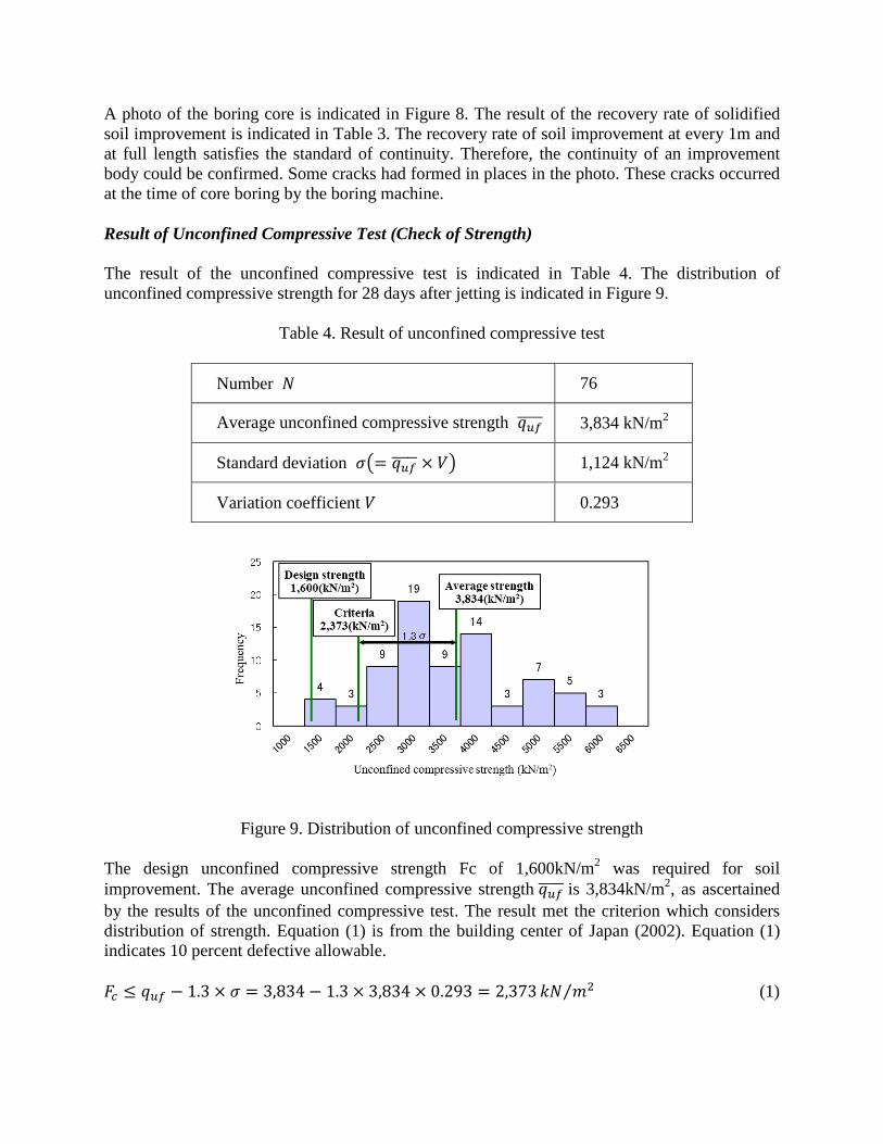
A photo of the boring core is indicated in Figure 8. The result of the recovery rate of solidified soil improvement is indicated in Table 3. The recovery rate of soil improvement at every 1m and at full length satisfies the standard of continuity. Therefore, the continuity of an improvement body could be confirmed. Some cracks had formed in places in the photo. These cracks occurred at the time of core boring by the boring machine. Result of Unconfined Compressive Test (Check of Strength) The result of the unconfined compressive test is indicated in Table 4. The distribution of unconfined compressive strength for 28 days after jetting is indicated in Figure 9.
Table 4. Result of unconfined compressive test
Number 𝑁𝑁 76
Average unconfined compressive strength 𝑞𝑞𝑢𝑢𝑢𝑢����� 3,834 kN/m2
Standard deviation 𝜎𝜎�= 𝑞𝑞𝑢𝑢𝑢𝑢����� × 𝑉𝑉� 1,124 kN/m2
Variation coefficient 𝑉𝑉 0.293
Figure 9. Distribution of unconfined compressive strength
The design unconfined compressive strength Fc of 1,600kN/m2 was required for soil improvement. The average unconfined compressive strength 𝑞𝑞𝑢𝑢𝑢𝑢����� is 3,834kN/m2, as ascertained by the results of the unconfined compressive test. The result met the criterion which considers distribution of strength. Equation (1) is from the building center of Japan (2002). Equation (1) indicates 10 percent defective allowable. 𝐹𝐹𝑐𝑐 ≤ 𝑞𝑞𝑢𝑢𝑢𝑢 − 1.3 × 𝜎𝜎 = 3,834 − 1.3 × 3,834 × 0.293 = 2,373 𝑘𝑘𝑁𝑁 𝑚𝑚2⁄ (1)

The variation coefficient of unconfined compressive strength 𝑉𝑉 is 0.293. The variation coefficient is about 0.45 (Yoshida (2009)) for conventional jet grouting, and about 0.20-0.45 for the deep mixing method (the building center of Japan (2002)). Therefore, soil improvement in this site could confirm the high quality in variation. Check of Adhesion to Slabs Adhesion is important in transferring the horizontal load acting on the structure to soil improvement. So we stopped jetting when we construct soil improvement at the top of the column. We injected shrinkage reducing mortar at the top of the column. Because slab is thin, check of adhesion to slab is done by visual judgment. We took pictures of connective states in guide hole by digital camera. Adhesion to a slab is indicated in Figure 10. Unevenness on the bottom surface of the slab didn’t influence adhesion to the slab. Adhesion to the slab was confirmed.
Figure 10. Adhesion to Slabs
Conclusions On this site, an investigation was carried out to confirm the quality of JETCRETE after construction. As the results, it was confirmed that soil improvement by JETCRETE meets the standards for recovery rate of boring cores, unconfined compressive strength, and adhesion to slabs. Therefore, we believe that the increase of bearing capacity and earthquake reinforcement for the difficult foundations of existing structures will be possible in severe conditions which have been regarded as difficult. This construction technique can be adaptable to similar severe condition (in operating and in narrow space), for example educational building and hospital.
References The Building Center of Japan. Design and criteria of quality control of ground improvement for buildings. 2002
H. Yoshida. Technical Problems and Vision of Jet Grouting. The Foundation Engineering & Equipment, vol. 37: Tokyo, 2009.