earthquake resistant design of low-rise open ground storey framed building … · 2017-04-07 ·...
TRANSCRIPT

@IJMTER-2015, All rights Reserved 94
EARTHQUAKE RESISTANT DESIGN OF
LOW-RISE OPEN GROUND STOREY FRAMED BUILDING
ADITYA DESHMUKH1
1P.G. Student (M-Tech - Structures), Nagpur University, Maharashtra
Abstract - Present study RC framed building (G+10) with open ground storey located in Seismic Zone-
II, III, IV and V is considered. The main objective of present study is the study of strengthing
performance of Open ground storey(OGS) buildings according to various cases such as: (a) bare frame
building (b)building with uniform infill in all storey (c) building with OGS (d) OGS with stiffer column
(e) OGS with corner shear wall (f) OGS with corner cross bracing (g) OGS with composite columns.
The separate models were generated using commercial software ETABS. Infill stiffness was modeled
using an equivalent diagonal strut approach. Parametric studies on displacement, storey drift, shear
force, bending moment and base shear have been carried out using equivalent static analysis to
investigate the influence of this parameter on the behavior of building with OGS.
Keywords – stiffness, infill wall, equivalent diagonal strut, strengthing of OGS building, seismic
analysis
I. INTRODUCTION
In general, multi-storeyed Reinforced concrete (RC) frame buildings in metropolitan cities require open
taller first storey for parking of vehicles i.e., columns in the ground storey do not have any partition
walls (of either masonry or RC) between them and/or for large space for meeting room or a banking hall
owing to lack of horizontal space and high cost are becoming increasingly common in India. Such
buildings are know as open ground storey buildings or stilts storey building. Open ground storey
buildings are inherently poor systems with sudden drop in stiffness and strength in the ground storey. In
the current practice, stiff masonry walls are neglected and only bare frames are considered in design
calculations. Thus, the inverted pendulum effect is not captured in design.
II INDIAN STANDARD IS 1893-2002
Stiffness Irregularity( soft storey) : a soft storey is one in which the later stiffness is less than 70
percent of that in storey above or less than 80 percent of the average lateral stiffness of the three storey
above
Stiffness Irregularity( Extreme soft storey) : a extreme soft storey is one in which the later stiffness is
less than 60 percent of that in storey above or less than 70 percent of the average lateral stiffness of the
three storey above. For example, building on STILTS will fall under this category
Clause 7.10.3 : The column and beams of the soft storey are to be designed for 2.5 times the storey
shears and moments calculated under seismic loads specified in the other relevant clauses.
III OBJECTIVE OF THE STUDY
Based on the literature review the salient objectives of the present study have been identified as follows:
International Journal of Modern Trends in Engineering and Research (IJMTER) Volume 02, Issue 04, [April – 2015] ISSN (Online):2349–9745 ; ISSN (Print):2393-8161
@IJMTER-2015, All rights Reserved 95
The effect of masonry infill stiffness in the seismic analysis of Open ground storey buildings.
Strengthening of Open Ground Story RC buildings.
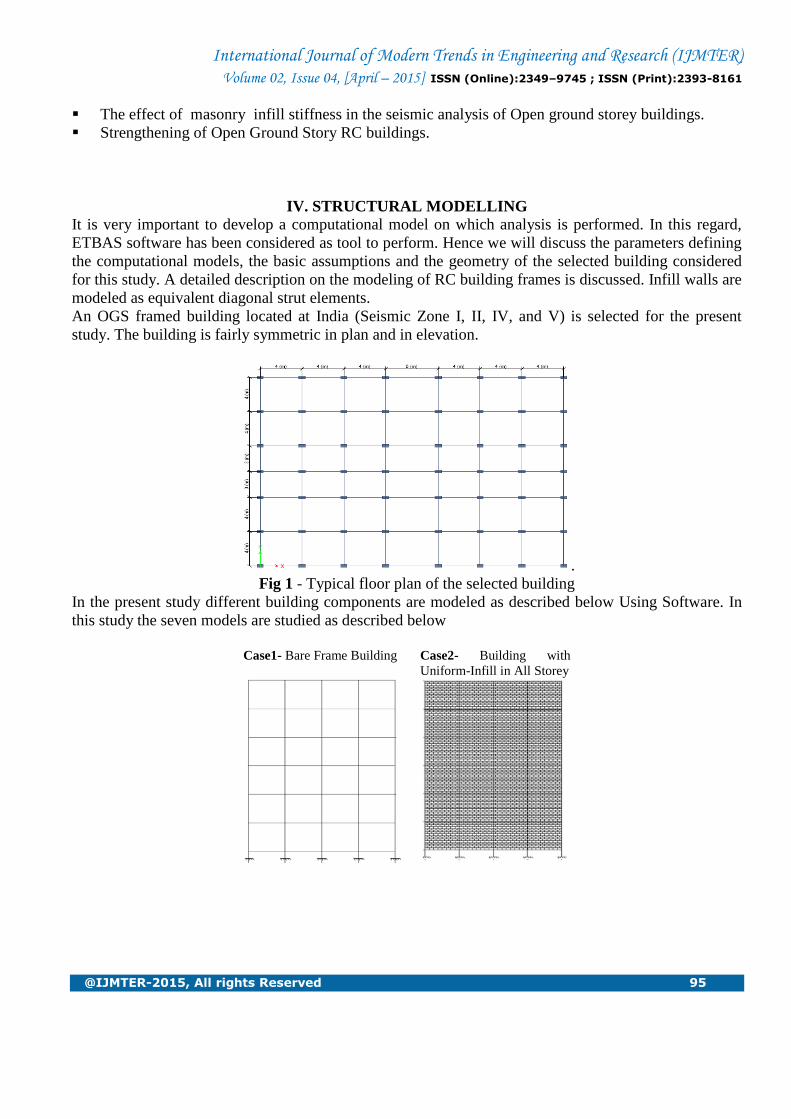
IV. STRUCTURAL MODELLING
It is very important to develop a computational model on which analysis is performed. In this regard,
ETBAS software has been considered as tool to perform. Hence we will discuss the parameters defining
the computational models, the basic assumptions and the geometry of the selected building considered
for this study. A detailed description on the modeling of RC building frames is discussed. Infill walls are
modeled as equivalent diagonal strut elements.
An OGS framed building located at India (Seismic Zone I, II, IV, and V) is selected for the present
study. The building is fairly symmetric in plan and in elevation.
.
Fig 1 - Typical floor plan of the selected building
In the present study different building components are modeled as described below Using Software. In
this study the seven models are studied as described below
Case1- Bare Frame Building Case2- Building with
Uniform-Infill in All Storey

International Journal of Modern Trends in Engineering and Research (IJMTER) Volume 02, Issue 04, [April – 2015] ISSN (Online):2349–9745 ; ISSN (Print):2393-8161
@IJMTER-2015, All rights Reserved 96
Case3- Building with Open
Ground Story
Case4- OGS with Stiffer
Column (MF 2.5)
Case5- OGS with Corner
Shear wall
Case6- OGS with Cross
Bracing
Case7- OGS with Composite
Column

International Journal of Modern Trends in Engineering and Research (IJMTER) Volume 02, Issue 04, [April – 2015] ISSN (Online):2349–9745 ; ISSN (Print):2393-8161
@IJMTER-2015, All rights Reserved 97
BUILDING DESCRIPTION
Plan dimensions : 31 m x 22m
Number of Storey : G+10
Total height of building : 33 m
Floor height : 3 m
Beam sizes : 300 x 500 mm
Column sizes : 300 x 600 mm
Slab thickness : 150 mm
Floor Live Load : 3 kN/m2
Roof live load : 1.5 kN/m2
Floor Finish Load : 0.5 kN/m2
Concrete grade : M25
Steel : Fe415
Earthquake parameters
Seismic zone : II, III, IV and V
Response Reduction Factor : 5
Importance Factor : 1
Type of soil : Medium
Damping of structure. : 5%
Modeling of Infill Walls In present study, infills wall in stories are modeled as equivalent diagonal strut (Proposed by Hendry in
1998) and its equivalent width (W) of a strut is given as,

International Journal of Modern Trends in Engineering and Research (IJMTER) Volume 02, Issue 04, [April – 2015] ISSN (Online):2349–9745 ; ISSN (Print):2393-8161
@IJMTER-2015, All rights Reserved 98
To determine αh and αl which depends on the relative stiffness of the frame and on the geometry of the
panel.
Where,
Em and Ef = Elastic modulus of the masonry wall and frame material, respectively
t, h, l = Thickness, height and length of the infill wall, respectively
Ic, Ib = Moment of inertia of the column and the beam of the frame, respectively
Ѳ = tan-1(h/L)
V. RESULT AND DISCUSSION
Later Displacement :-
The later displacement in columns in X-direction and Y-direction direction is considered for
analysis in seismic zone II, III, IV, and V shown in graphical representation of data is shown in Graph
no. 1 to 8
Graph 1 : Zone II, X-direction Graph 1: Zone II, X-direction
Graph 3 : Zone III, X-direction Graph 4 : Zone III, Y-direction
0
5
10
15
20
25
30
35
0 2 4 6 8 10 12
Dis
pla
ce
me
nt (
mm
)
Floor Level
Variation in X-Displacement Floorwise
CASE 1 CASE 2 CASE 3 CASE 4 CASE 5 CASE 6 CASE 7
0
5
10
15
20
25
30
35
40
45
0 2 4 6 8 10 12
Dis
pla
ce
me
nt (
mm
)
Floor Level
Variation in Y-Displacement Floorwise
CASE 1 CASE 2 CASE 3 CASE 4 CASE 5 CASE 6 CASE 7
0
5
10
15
20
25
30
35
40
0 2 4 6 8 10 12
Dis
pla
ce
me
nt (
mm
)
Floor Level
Variation in X-Displacement Floorwise
CASE 1 CASE 2 CASE 3 CASE 4 CASE 5 CASE 6 CASE 7
0
5
10
15
20
25
30
35
40
45
50
0 2 4 6 8 10 12
Dis
pla
ce
me
nt (
mm
)
Floor Level
Variation in Y-Displacement Floorwise
CASE 1 CASE 2 CASE 3 CASE 4 CASE 5 CASE 6 CASE 7

International Journal of Modern Trends in Engineering and Research (IJMTER) Volume 02, Issue 04, [April – 2015] ISSN (Online):2349–9745 ; ISSN (Print):2393-8161
@IJMTER-2015, All rights Reserved 99
Graph 5 : Zone IV, X-direction Graph 6: Zone IV, Y-direction
Graph 7 : Zone V, X-direction Graph 8 : Zone V, Y-direction
For comparison of the later displacement of the selected building, plots of the storey level displacement
in X-direction or Y-direction versus height are made for the seven cases, all imposed on the same graph.
The displacement is inversely proportional to the stiffness.
From the graphs it is observed that the displacements are large occurs in case of open ground storey
building (case 3).
In case 2, case 4, case 5, case 6 and case 7 displacement are reduced as compared to case 3 (open
ground storey).
Percentage reduction in displacement with respect to case 3 (OGS)
In zone II
Displacement Case 2 Case 4 Case 5 Case 6 Case 7
% reduction 25 47 58 22 25
In zone III
Displacement Case
2
Case
4
Case
5
Case
6
Case
7
% reduction 40 48 71 23 25
In zone IV
Displacement Case
2
Case
4
Case
5
Case
6
Case
7
% reduction 48 48 71 24 25
0
5
10
15
20
25
30
35
40
45
50
0 2 4 6 8 10 12
Dis
pla
ce
me
nt (
mm
)
Floor Level
Variation in X-Displacement Floorwise
CASE 1 CASE 2 CASE 3 CASE 4 CASE 5 CASE 6 CASE 7
0
10
20
30
40
50
60
0 2 4 6 8 10 12
Dis
pla
ce
me
nt (
mm
)
Floor Level
Variation in Y-Displacement Floorwise
CASE 1 CASE 2 CASE 3 CASE 4 CASE 5 CASE 6 CASE 7
0
10
20
30
40
50
60
0 2 4 6 8 10 12
Dis
pla
ce
me
nt (
mm
)
Floor Level
Variation in X-Displacement Floorwise
CASE 1 CASE 2 CASE 3 CASE 4 CASE 5 CASE 6 CASE 7
0
10
20
30
40
50
60
70
80
0 2 4 6 8 10 12D
isp
lace
me
nt (
mm
)Floor Level
Variation in Y-Displacement Floorwise
CASE 1 CASE 2 CASE 3 CASE 4 CASE 5 CASE 6 CASE 7
International Journal of Modern Trends in Engineering and Research (IJMTER) Volume 02, Issue 04, [April – 2015] ISSN (Online):2349–9745 ; ISSN (Print):2393-8161
@IJMTER-2015, All rights Reserved 100
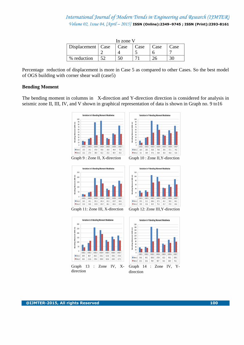
In zone V
Displacement Case
2
Case
4
Case
5
Case
6
Case
7
% reduction 52 50 71 26 30
Percentage reduction of displacement is more in Case 5 as compared to other Cases. So the best model
of OGS building with corner shear wall (case5)
Bending Moment
The bending moment in columns in X-direction and Y-direction direction is considered for analysis in
seismic zone II, III, IV, and V shown in graphical representation of data is shown in Graph no. 9 to16
Graph 9 : Zone II, X-direction Graph 10 : Zone II,Y-direction
Graph 11: Zone III, X-direction Graph 12: Zone III,Y-direction
Graph 13 : Zone IV, X-
direction Graph 14 : Zone IV, Y-
direction
CASE 1 CASE 2 CASE 3 CASE 4 CASE 5 CASE 6 CASE 7
Story 1 15.5 24.1 87.8 93.8 26.9 44.8 75.6
Story 2 13.2 27.4 38.0 42.2 23.2 40.9 43.2
0
10
20
30
40
50
60
70
80
90
100
Be
nd
ing
Mo
me
nt (
KN
-m)
Variation in X-Bending Moment Modelwise
CASE 1 CASE 2 CASE 3 CASE 4 CASE 5 CASE 6 CASE 7
Story 1 16.4 28.3 93.8 79.8 39.5 57.1 74.2
Story 2 8.2 30.9 47.6 58.8 36.5 46.0 52.6
0
10
20
30
40
50
60
70
80
90
100
Be
nd
ing
Mo
me
nt (
KN
-m)
Variation in Y-Bending Moment Modelwise
CASE 1 CASE 2 CASE 3 CASE 4 CASE 5 CASE 6 CASE 7
Story 1 26.5 44.1 191.1 181.3 82.3 120.7 164.1
Story 2 22.0 50.0 119.5 135.7 68.1 106.1 133.5
0
50
100
150
200
250
Be
nd
ing
Mo
me
nt
(KN
-m)
Variation in X-Bending Moment Modelwise
CASE 1 CASE 2 CASE 3 CASE 4 CASE 5 CASE 6 CASE 7
Story 1 29.5 31.2 106.4 97.5 44.2 58.9 86.3
Story 2 19.9 23.6 69.9 75.3 41.7 47.8 60.6
0
20
40
60
80
100
120
Be
nd
ing
Mo
me
nt (
KN
-m)
Variation in Y-Bending Moment Modelwise
CASE 1 CASE 2 CASE 3 CASE 4 CASE 5 CASE 6 CASE 7
Story 1 69.9 88.7 262.1 233.2 122.0 159.2 172.0
Story 2 40.4 112.6 170.4 190.0 102.6 130.5 117.5
0
50
100
150
200
250
300
Be
nd
ing
Mo
me
nt (
KN
-m)
Variation in X-Bending Moment Modelwise
CASE 1 CASE 2 CASE 3 CASE 4 CASE 5 CASE 6 CASE 7
Story 1 36.6 40.1 183.0 170.4 62.3 90.3 109.1
Story 2 25.5 32.6 78.9 98.7 54.5 68.9 76.1
0
20
40
60
80
100
120
140
160
180
200
Be
nd
ing
Mo
me
nt (
KN
-m)
Variation in Y-Bending Moment Modelwise

International Journal of Modern Trends in Engineering and Research (IJMTER) Volume 02, Issue 04, [April – 2015] ISSN (Online):2349–9745 ; ISSN (Print):2393-8161
@IJMTER-2015, All rights Reserved 101
Graph 15 : Zone V, X-direction Graph 16 : Zone V, Y-
direction
The bending moment is maximum in ground storey columns as compared to above storeys in case of
OGS building (case 3).
In open ground story with corner shear wall and open ground story with corner cross bracing the
moment are reduces by approximate 50-70% as compare to open ground storey building and very
effective from strength point of view these cases.
From the graphs it is observed that stiffer column and composite column (case 4 and case 7) increases
the bending moment in the ground storey column.
Storey Drift
The storey drift in columns in X-direction and Y-direction direction is considered for analysis in
seismic zone II, III, IV, and V shown in graphical representation of data is shown in Graph no. 17 to 24
Graph 17 : Zone II, X-direction Graph 18: Zone II, Y-direction
Graph 19 : Zone III, X-
direction
Graph 20 : Zone III, Y-
direction
CASE 1 CASE 2 CASE 3 CASE 4 CASE 5 CASE 6 CASE 7
Story 1 107.9 161.9 358.7 340.1 185.5 245.6 265.1
Story 2 68.0 185.4 226.2 240.9 188.3 203.2 163.5
0
50
100
150
200
250
300
350
400
Be
nd
ing
Mo
me
nt (
KN
-m)
Variation in X-Bending Moment Modelwise
CASE 1 CASE 2 CASE 3 CASE 4 CASE 5 CASE 6 CASE 7
Story 1 42.1 78.6 248.1 246.5 90.6 145.8 194.2
Story 2 40.0 52.4 139.2 180.0 78.3 99.8 112.6
0
50
100
150
200
250
300
Be
nd
ing
Mo
me
nt (
KN
-m)
Variation in Y-Bending Moment Modelwise
0
0
0
1
1
1
1
1
2
2
0 2 4 6 8 10 12
Drif
t (
mm
)
Floor Level
Variation in X-Drift Floorwise
CASE 1 CASE 2 CASE 3 CASE 4 CASE 5 CASE 6 CASE 7
0
1
1
2
2
3
0 2 4 6 8 10 12
Drif
t (
mm
)
Floor Level
Variation in Y-Drift Floorwise
CASE 1 CASE 2 CASE 3 CASE 4 CASE 5 CASE 6 CASE 7
0
1
1
2
2
3
0 2 4 6 8 10 12
Drif
t (
mm
)
Floor Level
Variation in X-Drift Floorwise
CASE 1 CASE 2 CASE 3 CASE 4 CASE 5 CASE 6 CASE 7
0
1
1
2
2
3
3
4
4
0 2 4 6 8 10 12
Drif
t (
mm
)
Floor Level
Variation in Y-Drift Floorwise
CASE 1 CASE 2 CASE 3 CASE 4 CASE 5 CASE 6 CASE 7

International Journal of Modern Trends in Engineering and Research (IJMTER) Volume 02, Issue 04, [April – 2015] ISSN (Online):2349–9745 ; ISSN (Print):2393-8161
@IJMTER-2015, All rights Reserved 102
Graph 21 : Zone IV, X-
direction
Graph 22 : Zone IV, Y-
direction
Graph 23 : Zone V, X-direction Graph 24 : Zone V, X-
direction
From the graphs it is observed that the storey drift is large for open ground storey (case 3).
Storey drift profile becomes smooth from case 4 to case 7 indicating more stiffness.. Stiffer columns
(case 4) and composite column (case 7) reduces the storey drift at first floor level.
Base Shear
The base shear in columns in X-direction and Y-direction direction is considered for analysis in seismic
zone II, III, IV, and V shown in graphical representation of data is shown in Graph no. 25 to 28
Graph 25 : Zone II Graph 26 : Zone III
0
1
1
2
2
3
3
4
4
0 2 4 6 8 10 12D
rif
t (
mm
)
Floor Level
Variation in X-Drift Floorwise
CASE 1 CASE 2 CASE 3 CASE 4 CASE 5 CASE 6 CASE 7
0
1
2
3
4
5
6
0 2 4 6 8 10 12
Drif
t (
mm
)
Floor Level
Variation in Y-Drift Floorwise
CASE 1 CASE 2 CASE 3 CASE 4 CASE 5 CASE 6 CASE 7
0
1
2
3
4
5
6
0 2 4 6 8 10 12
Drif
t (
mm
)
Floor Level
Variation in X-Drift Floorwise
CASE 1 CASE 2 CASE 3 CASE 4 CASE 5 CASE 6 CASE 7
0
1
2
3
4
5
6
7
8
9
0 2 4 6 8 10 12
Drif
t (
mm
)Floor Level
Variation in Y-Drift Floorwise
CASE 1 CASE 2 CASE 3 CASE 4 CASE 5 CASE 6 CASE 7
CASE 1 CASE 2 CASE 3 CASE 4 CASE 5 CASE 6 CASE 7
X-direction 1451 8191 5032 6391 7072 5441 5727
Y-direction 1068 6311 3588 5020 5710 4132 3859
0
1000
2000
3000
4000
5000
6000
7000
8000
9000
Ba
se
Sh
ea
r (
KN
)
Variation in Base Shear Building Modelwise
CASE 1 CASE 2 CASE 3 CASE 4 CASE 5 CASE 6 CASE 7
X-direction 2321 13105 8051 10226 11315 8705 9163
Y-direction 1709 10098 5740 8032 9135 6611 6175
0
2000
4000
6000
8000
10000
12000
14000
Ba
se
Sh
ea
r (
KN
)
Variation in Base Shear Building Modelwise

International Journal of Modern Trends in Engineering and Research (IJMTER) Volume 02, Issue 04, [April – 2015] ISSN (Online):2349–9745 ; ISSN (Print):2393-8161
@IJMTER-2015, All rights Reserved 103
Graph 27 : Zone IV Graph 28 : Zone V
The base shear is directly proportional to weight of structure
From the graphs base shear profiles it is observed that minimum shear occurs in open ground storey
building (case 3).
It is observed that the use of uniform infill in all storeys in the first storey increase the base shear up to
68% as compared with case3. Stiffer column and beam (case 4) increase the base shear to 33% of case
3. By introducing Corner shear wall (case 5) increase the base shear to 45% of case 3. Corner cross
bracing (case 6) increase the base shear to 12% of case 3. Composite column and beam (case 7) increase
the base shear to10% of case 3.
VI. CONCLUDING REMARKS
1. Underestimation of design base shear in case of bare frame models as compared to the infill
models the design base shear increases with increase in mass and stiffness of masonry infill wall and
vice versa.
2. Infill panel increases the later stiffness of the building, measured in terms of first story
displacement there by reducing displacement in all storey levels compared to open ground story building
cases.
3. Open ground story with shear wall and cross bracing are found to be very effective in reducing
the stiffness irregularity and bending moment in the column.
4. Open ground story with stiffer column and composite columns are effective in reducing the
stiffness irregularity and drift, but there is increase in the shear force and bending moment in the first
story.
5. Ductility if found more in the infill frame panel compare to the open ground story building
models.
REFERENCES Journal paper: 1. Holmes, M. (1961) Steel frames with brick and concrete infilling. Proceedings of Institution of Civil Engineers.
2. Arlekar, J.N.; S. K. Jain and C.V.R Murty (1997) Seismic response of RC frame buildings with soft first storeys.
Proceedings of CBRI golden jubilee conference on natural hazards in urban habitat. New Delhi
3. Riddington, J. R. and S. B. Smith (1977) Analysis of infilled frames subject to racking with design recommendations.
The Structural Engineer.
4. Davis, P. R., (2009) Earthquake Resistant Design of Open Ground Storey RC Framed Buildings. Ph.D. Thesis, Indian
Institute of Technology Madras, Chennai.
5. Smith, S. B. (1966) Behaviour of Square Infilled frames. ASCE Journal of the Structural Division. 92. 381-403
6. S. B. Smith and C. Carter, (1969) A Method of Analysis for Infilled Frames. Proceedings of Institution of Civil
Engineers.
7. P.B.Lamb, Dr R.S. Londhe(2012) Seismic Behavior of Soft First Storey, Proceedings of IOSR Journal of Mechanical
and Civil Engineering.
CASE 1 CASE 2 CASE 3 CASE 4 CASE 5 CASE 6 CASE 7
X-direction 3482 19658 12076 15339 16972 13057 13745
Y-direction 2564 15147 8611 12049 13703 9916 9262
0
2000
4000
6000
8000
10000
12000
14000
16000
18000
20000
Ba
se S
he
ar
(KN
)
Variation in Base Shear Building Modelwise
CASE 1 CASE 2 CASE 3 CASE 4 CASE 5 CASE 6 CASE 7
X-diretion 5223 29487 18114 23008 25458 19586 20617
Y-direction 3845 22721 12916 18073 20555 14874 13893
0
5000
10000
15000
20000
25000
30000
Ba
se S
he
ar
(KN
)
Variation in Base Shear Building Modelwise
International Journal of Modern Trends in Engineering and Research (IJMTER) Volume 02, Issue 04, [April – 2015] ISSN (Online):2349–9745 ; ISSN (Print):2393-8161
@IJMTER-2015, All rights Reserved 104
8. Selvakoodalingam, B.; E. B. Perumal Pillai and P. Govindan (1999) Strengthening of RC Infilled frame with opening.
Concrete International.
9. Bureau of Indian Standards: IS-1893, part 1 (2002), “Criteria for Earthquake Resistant Design of Structures: Part 1
General provisions and Buildings”, New Delhi, India.
10. C.V.R Murty, Indian Institute of Technology Kanpur, Earthquake tips, India.
Books:
P. Agrawal, M. Shrikhande(2009) earthquake resistant design of structures (PHI Learning Pvt.Ltd. New delhi,
