eas 553/4 advanced structural design -...
TRANSCRIPT

UNIVERSITI SAINS MALAYSIA
2nd
. Semester Examination
2001/2002 Academic Session
FEBRUARY / MARCH 2002
EAS 553/4 – Advanced Structural Design
Time : 3 hours
Direction to student:-
1. Ensure that this paper contains TWENTY FOUR (24) printed pages include
appendices.
2. This paper contains SEVEN (7) question. Answer FIVE (5) question only. Marks
will be given to the FIRST FIVE (5) question put in order on the answer script and
NOT the BEST FIVE (5).
3. All questions carry the same mark.
4. All questions MUST BE answered in Bahasa Malaysia.
5. Write answered question number on the cover sheet of answer script.
…2/-

- 2 - [EAS 553/4]
1. (a) Define what is the meaning of formwork and falsework. ( 4 marks)
(b) Figure 1 shows a reinfoced concrete retaining wall with 4.5 m height and 400
mm thick, supported by a timber element AB which is spacing of 5m centre to
centre. Given the type of concrete is OPC with 30% PFA, temperature during
concreting is 20C, width of the wall is 5.0 m and the pouring rate for the
concrete is 3m3/hr.
i. Calculate the pressure exerted on the wall. ( 3 marks)
ii. Calculate the force exerted on bending member AC in kN/m and the axial
force in member AB in kN.
( 3 marks)
iii. If a solid timber, group A - wet, standard, is going to be used for the
design of the bending member AC to carry out the short term loading find
the minimum and norminal size of member AC to withstand the force in
section 1b)ii.
( 8 marks)
iv. Explain whether member AB and CD experience a sharing load factor?
( 2 marks)
Figure 1
…3/-
80 mm
80 mm
RC
retaining
wall
B
A
400 mm
4.5 m
Supporting member
2.0 m
C
D

- 3 - [EAS 553/4]
2 (a) An industrial building shown in Figure 2, situated at Ipoh in the terain category 3
with the basic wind speed of 33.5 m/s2 is built for the furniture’s factory.
Assumed that it is made of steel structure, find the maximum wind pressure on
W (windward), L (leeward), S (sidewall), U (upwind) and D (downwind) surfaces.
Hence sketch the net wind pressures for each surface.
(15 marks)
(b) The industrial building is also equipped with a signboard of 50m x 1m on
windward surface as shown in Figure 2. Assumed that it is a cladding element,
find the maximum pressure experienced by the signboard.
Design data is given in Appendix B
( 5 marks)
60 m
30 m
30 m
6 m
80 m
2E
Figure 2
1m
signboard
Wind direction
15 m
15m

…4/-
- 4 - [EAS 553/4]
3. An open cylindrical tank as shown in Fig. 3 to store treated sewerage is to be
constructed with an internal diameter of 33.5 m and a maximum liquid depth of
9.5 m. The wall of the tank is to be of uniform thickness. The sewerage is to be
regarded as water for loading considerations. The walls are to be considered as
being continuous with the base and with a free top.
Materials:
fcu=35 N/mm2 , fct=1.5 N/mm
2 , Ec=30 kN/mm
2
fy= 460 N/mm2 , fs=130 N/mm
2, Es=200 kN/mm
2
Self-weight:
concrete =24 kN/m3 ; water = 9.81 kN/m
3
Formula for membrane stress resultants:
Nx= - px + C ; N= pr .a
(a) Estimate the required wall thickness. ( 8 marks)
(b) Design the vertical and hoop reinforcements. (12 marks)
Figure 3
0.5m
33.5 m
9.5 m
cylindrical
tank
sewerage
base

…5/-
- 5 - [EAS 553/4]
4. (a) Draw and show the behaviour of simply supported and continuous steel beam
under load in the position of elastic, elastic-plastic and fully plastic. Explain
briefly the relationship between the applied load against the deflection at the mid-
span of the beam.
(5 marks)
(b) State FOUR (4) required assumptions in the plastic design when the plastic
hinged develop in the steel member.
(5 marks)
(c) Figure 4 shows a continous beam having three unequal span subjected to several
point loads. Design the cross-section of steel beam (Appendix D) based upon:
i. Uniform section
ii. Non-uniform section
Figure 4
(10 marks)
5. Figure in Appendix E shows the table for standard PCA inverted-T sections. A
simply supported prestressed beam with a span of 10 m will be designed for resisting
a live load of 25 kN/m.
(a) Select a suitable section from the table. Determine the amount of strands
required. Obtain the range of eccentricity e.
(10 marks)
(b) Plot the allowable cable zone if variable cable profile is used with the same
amount of strands. Sketch the appropriate strand arrangement for the profile.
(10 marks)
3 m 3 m 3 m 3 m 3 m
380 kN 360 kN 360 kN 470 kN
A B C D
6 m 9 m 4.5 m
…6/-
- 6 - [EAS 553/4]
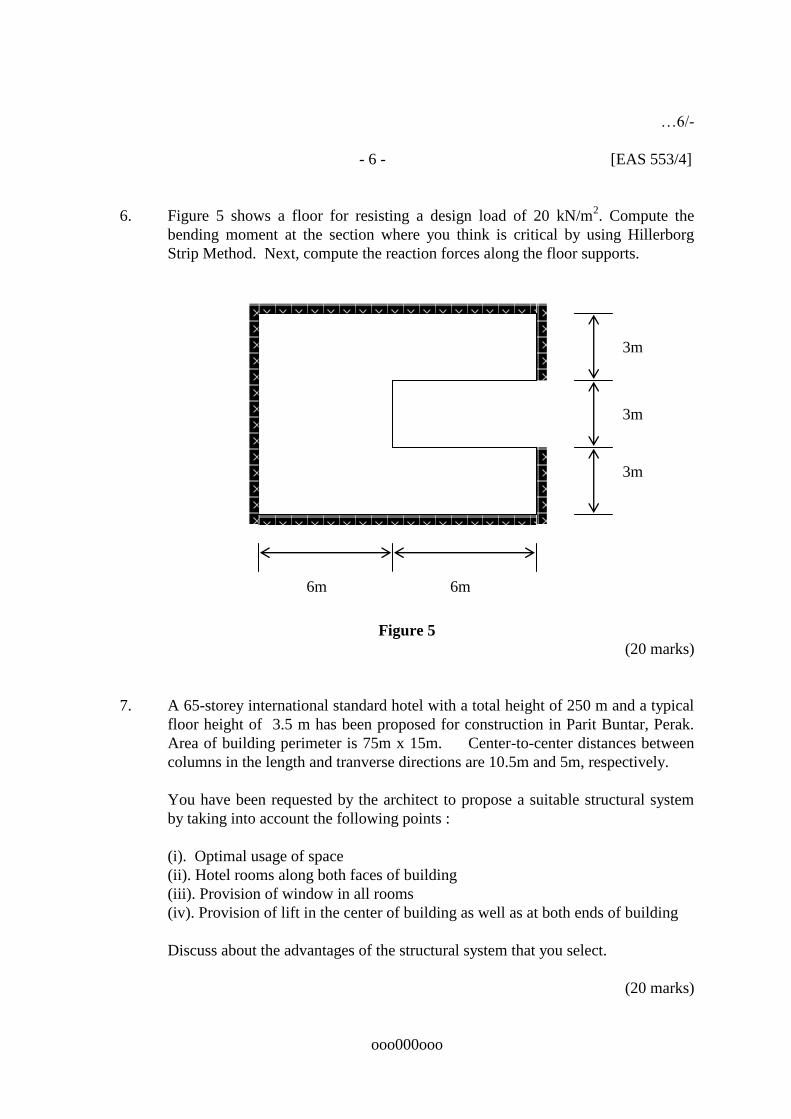
6. Figure 5 shows a floor for resisting a design load of 20 kN/m2. Compute the
bending moment at the section where you think is critical by using Hillerborg
Strip Method. Next, compute the reaction forces along the floor supports.
Figure 5
(20 marks)
7. A 65-storey international standard hotel with a total height of 250 m and a typical
floor height of 3.5 m has been proposed for construction in Parit Buntar, Perak.
Area of building perimeter is 75m x 15m. Center-to-center distances between
columns in the length and tranverse directions are 10.5m and 5m, respectively.
You have been requested by the architect to propose a suitable structural system
by taking into account the following points :
(i). Optimal usage of space
(ii). Hotel rooms along both faces of building
(iii). Provision of window in all rooms
(iv). Provision of lift in the center of building as well as at both ends of building
Discuss about the advantages of the structural system that you select.
(20 marks)
ooo000ooo
6m 6m
3m
3m
3m

…7/-
- 7 - [EAS 553/4]
APPENDIX A
Jadual 1.6 : Tegasan dan modulus keanjalan lembap* untuk kumpulan kekuatan ( N/mm2) (MS 544 – Table 3.4)
Kumpulan Gred Lentur Tegangan selari
dengan ira
Mampatan
selari dengan
ira
Mampatan
serenjang
dengan ira
Ricih selari
dengan ira
Modulus keanjalan
Purata Minimum
A Asas
Select
Standard
Common
20.70
16.50
12.75
10.30
-
9.90
7.65
6.18
17.20
13.80
10.70
8.60
1.72
1.45
1.38
1.24
2.75
1.93
1.52
1.24
13 790
8 620
B Asas
Select
Standard
Common
17.20
13.80
10.34
8.60
-
8.28
6.20
5.16
13.80
11.00
8.60
6.90
1.03
0.87
0.83
0.76
2.07
1.45
1.10
0.90
11 030
6 205
C Asas
Select
Standard
Common
12.40
9.93
7.58
6.20
-
5.96
4.55
3.72
9.65
7.58
5.86
4.83
0.69
0.59
0.55
0.52
1.38
0.96
0.76
0.62
8 960
5 170
D Asas
Select
Standard
Common
7.58
5.86
4.48
3.79
-
3.52
2.69
2.27
6.55
5.17
3.79
3.24
0.41
0.34
0.31
0.28
1.38
0.97
0.76
0.62
5 720
2 965
Nota : * Kayu yang mempunyai kandungan lembapan lebih daripada 19%
Tegangan selari dengan ira = 0.6 x nilai tegasan lentur. Ini merupakan pindaan daripada MS 544 yang dibuat oleh penulis ( bukan oleh SIRIM) berasaskan BS 5268:
Part 2: 1984
Data rekabentuk anggota lenturan :
Sistem yang mempunyai dua atau tiga anggota yang menaggung beban bersama-
sama, nilai modulus keanjalan ialah N
EEEE
mp
pN
Panjang
Galas(mm)
10 15 25 40 50 75 100 ≥150
Nilai K2 1.74 1.67 1.53 1.33 1.20 1.14 1.10 1.00
Rasuk ditakik dibahagian bawah
D
DK e1.3
Rasuk ditakik dibahagian atas Deuntuke
D
DD
D
DK
e
e
e
22.3
0.12.3 K untuk e ≥ D
6.0daripadakurangtidakD
De
K4 = 1.18
K4 = 1.41

Ukur dalam rasuk, mmDuntukD
DK 300
56800
9230081.0
2
2
5
- 8 - [EAS 553/4]
APPENDIX A
Kestabilan sisi, Jadual 2.4: Nisbah ukur dalam kepada lebar (anggota pejal)
Darjah sokongan sisi Nisbah maksimum ukur dalam-
lebar
Tiada sokongan sisi.
Hujung-hujung dipegang pada kedudukannya.
Hujung-hujung dipegang pada kedudukannya dan anggota dipegang dalam barisan,
seperti oleh gulung-gulung atau batang pengikat.
Hujung-hujung dipegang pada kedudukannnya dan bahagian mampatan dipegang
dalam barisan, seperti secara sambungan langsung dengan papan lantai, geladak
atau gelegar.
Hujung-hujung dipegang pada kedudukannya dan bahagian mampatan dipegang
dalam barisan, seperti secara sambungan langsung dengan papan lantai, geladak atau
gelegar, beserta dengan rembatan yang cukup pada jarak luang tidak melebihi 6 kali ukur
dalamnya.
Hujung-hujung dipegang pada kedudukannya dan kedua-dua bahagian atas dan
bawah anggota dipegang teguh dalam barisan.
2
3
4
5
6
7
Tegasan lentur, fs fp iaitu fs=M/Z dan fp = fg X K1 X Kkb X K4 X K5
Tegasan ricih, qs qp iaitu qs = 1.5 V/A dan qp = qg X K1 X Kkb X K3
Pesongan, s < p iaitu s = 5wL4/384EI + FMo /GA dan p = 0.003L
Tegasan galas, Cts Ctp iaitu Cts = R/Aa dan Ctp = Ctg X K1 X Kkb X K2
Data rekabentuk anggota mampatan :
E minimum perlu digunkan untuk anggota mampatan.
Csg ialah mampatan selari dengan ira
Nisbah kelangsingan = r
Le iaitu r =
A
I
Anggapan Lex = Ley = 1.0 LAB
Tegasan izin = Csg x K6 x Kkb

Beban izin = Tegasan izin x luas keratan
- 9 - [EAS 553/4]
APPENDIX B
A P P E N D I X A
(normative)
S I M P L I F I E D P R O C E D U R E A1. Limitations
The simplified procedure of analysis shall be applied to the design of cladding and main
structural system of building structures, which meet all of the following criteria:
a) the buildings are rectangular in plan, or a combination of rectangular units;
b) the average roof height of a structure, h, is not greater than 15.0m.
c) the ratio of the average roof height to the least horizontal dimension does not
exceed 3.
d) the location of structure is not at unusually exposed locations such as hill-crest or
at headland; and
e) the following types of building is considered in this section:
i) buildings and structures where the primary occupancy is one in which
more than 300 people congregate in one area.
ii) essential buildings and structures
iii) hospital and medical facilities
iv) fire and police stations
v) structures and equipment in civil defense
vi) communication centres and facilities for emergency response
vii) power stations and other emergency utilities
viii) defense shelter.
A2. Procedures A2.1 The design wind pressures, p in Pa, shall be taken as
a) p = 0.613 (Vs)2(Mz,cat)2(CpeKl - Cpi) for cladding,
b) p = 0.613(Vs)2(Mz,cat)2(Cpe - Cpi) for structural system,
where :
Vs 33.5 m/s and 32.5 m/s for Zone I and Zone II respectively (see Figure
A1)
(Mz,cat) terrain/height multiplier as given in Table A2
Cpe external pressure coefficients for surfaces of enclosed building as

given in Section A2.3 and A2.4
Cpi internal pressure coefficients for surfaces of enclosed buildings which
shall be taken as +0.6 or –0.3. The two cases shall be considered to
determine the critical load requirements for the appropriate condition.
Kl Local pressure factor as given in Table A8 and Figure A2
- 10 - [EAS 553/4]
APPENDIX B A2.2 The design wind pressure used in the design of cladding and main structural system
shall not be less than 0.65 kN/m2.
Table A2. Terrain height multiplier, Mz,cat
Height, z
(m)
Mz,cat Terrain
Category
1
Terrain
Category
2
Terrain
Category
3
Terrain
Category
4
≤3 0.99 0.85 0.75 0.75
5 1.05 0.91 0.75 0.75
10 1.12 1.00 0.83 0.75
15 1.16 1.05 0.89 0.75
NOTE. Terrain Category Definition
a) Category 1 : Exposed open terrain with few or no obstructions.
b) Category 2 : Water surfaces, open terrain, grassland with few well scattered obstructions having height generally from 1.5m to 10.0m.
c) Category 3 : Terrain with numerous closely spaced obstructions 3.0m to 5.0m high such as areas of suburban housing. d) Category 4 : Terrain with numerous large, high (10.0m to 30.0m high) and closely spaced obstructions such as large city centres and well- developed industrial complexes.
A2.3 The external pressure coefficients, Cp,e, for windward wall shall be taken as 0.8.
Cp,e for leeward and side wall shall be as per Table A3 and A4 respectively.
Table A3. External pressure coefficients Cp,e, for leeward wall
*
d/b*
Cp,e
≤10°
≤1 2 ≥4
-0.5 -0.3 -0.2
15° 20° ≥25°
All values
-0.3 -0.4 -0.5
* For intermediate values of d/b and , use linear interpolation.

Table A4. External pressure coefficients Cp,e, for side walls
Horizontal distance from
windward edge
Cp,e
0 to 2h
>2h
-0.65 -0.30
- 11 - [EAS 553/4]
APPENDIX B
A2.4 The external pressure coefficients, Cpe, for roofs shall be as per Table A5, A6 and A7.
Table A5. For up-wind slope, u and down-wind slope, d for <10 and R for gable roofs
Roof type and slope
Horizontal distance
from windward edge
External pressure coefficient, Cp,e
Cross wind slopes
for gable roofs, R
Up- wind slopes, U,
Down-wind slope,
D
h/d 0.5**
h/d 1.0**
All
< 10
0 to 1h
1h to 2h
> 2h
-0.9, -0.4
-0.5, 0
-0.3, 0.2
-1.3, -0.6
(-0.7)*, (-0.3)*
Table A6. Up-wind slope, U, 10
Roof type
And slope
Ratio
h/d
External pressure coefficients, Cp,e
Up-wind
Slope, U
Roof pitch, degrees *
10 15 20 25 30 35 45
10
0.25
-0.7, -0.3
-0.5, -0.0
-0.3, -0.2
-0.2, -0.3
-0.2, -0.4
-0.0, 0.5
0, 0.8sin
0.5
-0.9, -0.4
-0.7, -0.3
-0.4, -0.0
-0.3, -0.2
-0.2, -0.3
-0.2, 0.4
1.0
-1.3, -0.6
-1.0, -0.5
-0.7, -0.3
-0.5, -0.0
-0.3, -0.2
-0.2, 0.3
Table A7. Down-wind slope, D, 10 and R for hip roofs
Roof type and slope
Ratio
h/d*
External pressure coefficient, Cp,e
Cross-wind
slopes for hip
roof, R
Down-wind
slopes, D
Roof pitch, degrees*
All
10
10
15
20
0.25
-0.3
-0.5
- 0.6
0.5
-0.5
-0.5
-0.6
1.0
-0.7
-0.6
-0.6
* Interpolation shall only be carried out on values of the same sign. * For intermediate values of roof slopes and h/d ratios, use linear interpolation

- 12 - [EAS 553/4]
APPENDIX B
Table A8. Local pressure factor, Kl for claddings
Design case
Figure A2
reference
number
h (m)
Area, A
Proximity to
edge
Kl
Positive
pressures
Windward wall
All other areas
WA1 -
All
All
A 0.25a2
-
Anywhere
-
1.25
1.0
Negative
pressures
Roof edges
RA1
RA2
All
All
0.25a2 < A a
2
A 0.25a
2
< a
< 0.5a
1.5
2.0
Hips and ridges of roofs
With pitch 10
RA3
RA4
All
All
0.25a
2 < A a
2
A 0.25a
2
< a
< 0.5a
1.5
2.0
Side walls near Windward wall
edges
SA1
SA2
25
0.25a
2 < A a
2
A 0.25a
2
< a
< 0.5a
1.5
2.0
SA3
SA4
SA5
> 25
A 0.25a
2
0.25a2 < A a
2
A 0.25a
2
> a
< a
< 0.5a
1.5
2.0
3.0
All other areas
-
All
-
-
1.0
NOTES: 1. The dimension, a, and the Figure reference numbers are defined in Figure A2 2. Design cases attracting Kl = 1.5 or 3.0 are alternative cases and need not be applied simultaneously. 3. The areas for local pressure factor are not necessarily square.

- 13 - [EAS 553/4]
APPENDIX B

WA1SA2
SA1
RA1RA2
RA4
RA3
RA1
RA2
WA1
SA3
SA4
SA5
SA2
WA1SA1
RA1
RA2
b
bd a
a
bda
a
h< 25m
h< 25m
h< 25m
d
Note: The value of the dimension a, is the minimum of 0.2b, 0.2d and h
Figure A2. Local pressure factors (Kl)
- 14 - [EAS 553/4]
APPENDIX C
Steel Area Section
Table 1

Sectional areas of groups of bars (mm2)
Bar size
(mm)
Number of bars
1 2 3 4 5 6 7 8 9 10
6 28.3 56.6 84.9 113 142 170 198 226 255 283
8 50.3 101 151 201 252 302 352 402 453 503
10 78.5 157 236 314 393 471 550 628 707 785
12 113 226 339 452 566 679 792 905 1020 1130
16 201 402 603 804 1010 1210 1410 1610 1810 2010
20 314 628 943 1260 1570 1890 2200 2510 2830 3140
25 491 982 1470 1960 2450 2950 3440 3930 4420 4910
32 804 1610 2410 3220 4020 4830 5630 6430 7240 8040
40 1260 2510 3770 5030 6280 7540 8800 10100 11300 12600
Table 2
Sectional areas per metre width for various bar spacing (mm2)
Bar
size
(mm)
Spacing of bars
50 75 100 125 150 175 200 250 300
6 566 377 283 226 189 162 142 113 94.3
8 1010 671 503 402 335 287 252 201 168
10 1570 1050 785 628 523 449 393 314 262
12 2260 1510 1130 905 754 646 566 452 377
16 4020 2680 2010 1610 1340 1150 1010 804 670
20 6280 4190 3140 2510 2090 1800 1570 1260 1050
25 9820 6550 4910 3930 3270 2810 2450 1960 1640
32 16100 10700 8040 6430 5360 4600 4020 3220 2680
40 25100 16800 12600 10100 8380 7180 6280 5030 4190