easing cracks with the method of tensile triangles
TRANSCRIPT

Easing cracks with the
C. Mattheck, C. Wissner, I. Tesari & K. Bethge Karlsruhe Institute of Technology (KIT), Germany
Abstract
The “Method of Tensile Triangles” was introduced as a design tool that mimics the rules of nature for the shape optimization of a design scheme with respect to increased fatigue life and reduced weight. It was inspired by the shape of buttress roots in trees. Like them it bridges a corner-like notch with tensile loaded triangles. The notch shape may be scaled up and down according to the individual design space limitations of the technical structure. Failure often starts at the cracks tips and slot ends in technical components, because these domains are highly loaded due to stress concentrations. Conventional rounding or drilling away of these crack tips can only lower the stresses. By means of the “Method of Tensile Triangles”, stress concentrations can be minimized and the endings redesigned and compressed. In this paper the “Method of Tensile Triangles” will be explained and it will be shown, by results of Finite Element analyses, how the destructive effect of crack tips and slot ends in technical components can be eliminated. Keywords: method of tensile triangles, shape optimization, crack arrest, stress concentrations.
1 Introduction
Good mechanical constructions are reliable during their estimated lifetime, are light-weight and have a high load-capability. One of the main reasons for failure is local stress concentrations, which occur where the force flow is disturbed, e.g. at notches even if they are rounded and not sharp. The stress concentrations at notches on the surface of a component cause material fatigue during its lifetime. Therefore, the prevention of such stress-raising effects is of great importance in nature as well as in engineering design. Trees make any effort to grow into a
www.witpress.com, ISSN 1743-3541 (on-line) WIT Transactions on Ecology and the Environment, Vol 138, © 2010 WIT Press
Design and Nature V 461
doi:10.2495/DN100411
Method of Tensile Triangles

homogeneous state of stress on their surface [1] and reduce stress peaks by adaptive growth. Based on the Finite Element Method (FEM), this principle was transferred into technical application and used for the optimization of technical components. Further studies show that an optimized shape can also be found much more easily than by use of laborious FE-calculations with the ‘Method of Tensile Triangles’, which is a new and easy graphic optimization method. The Tensile Triangles contour was found in many natural structures [2] and applied with good results in terms of stress reduction to different technical problems [3, 4], such as transitions and shoulder fillets in shafts and bars, screws etc. If slots and cracks are loaded perpendicular to their longitudinal axis, due to the smaller radii the slot ends and crack tips often have higher stress concentrations, e.g. in shaft fillets. So, failure often starts at the cracks tips and slot ends. Conventional rounding or drilling away of these crack tips can only lower the stresses.
2 Material and methods
2.1 Method of Tensile Triangles
Like buttress roots in trees, the Method of Tensile Triangles bridges corner-like notches with a tensile loaded triangle (fig. 1). The tree stem forms a sharp cornered notch with the ground surface. It bridges and defuses this corner by the root spur (buttress), which is usually most pronounced on the windward side. The sawn section through the root shows very large growth increments on the upper side. This one-sided root growth forms the Tensile Triangle. Technical components usually are not able to grow, so stress concentrations have to be minimised early in the design process, which can easily be done by the Method of Tensile Triangles. Starting from the 45° angle at the bottom, a triangle bridges the sharp corner (fig. 2). This procedure creates two notches of larger angles, which are less dangerous because the more obtuse the angle of a corner-like notch is the lower is the stress concentration there. After repeating the procedure one or two times and smoothing the remaining kinks with radii, one has a close-to-optimum notch contour or at least a highly improved notch shape with significant stress reduction. Even if the grown wood has a fibrous structure and therefore has mainly orthotropic material properties, and on the other hand most technical materials are almost isotropic, there is little difference in optimal shapes. Because the wood fibre direction is largely in agreement with the force flow in the tree, the smaller transverse effects are somewhat falsified due to using only the Youngs-modulus in the grain direction [1].
2.2 Stress concentrations at slot ends and crack tips
If slots and cracks are loaded perpendicular to their longitudinal axis, due to the small radii at the slot ends and cracks, high stress concentrations occur there,
www.witpress.com, ISSN 1743-3541 (on-line) WIT Transactions on Ecology and the Environment, Vol 138, © 2010 WIT Press
462 Design and Nature V
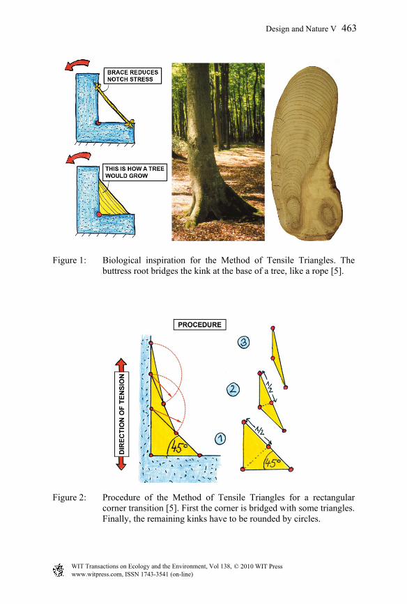
Figure 1: Biological inspiration for the Method of Tensile Triangles. The buttress root bridges the kink at the base of a tree, like a rope [5].
Figure 2: Procedure of the Method of Tensile Triangles for a rectangular corner transition [5]. First the corner is bridged with some triangles. Finally, the remaining kinks have to be rounded by circles.
www.witpress.com, ISSN 1743-3541 (on-line) WIT Transactions on Ecology and the Environment, Vol 138, © 2010 WIT Press
Design and Nature V 463
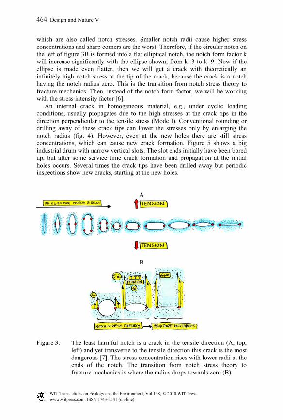
which are also called notch stresses. Smaller notch radii cause higher stress concentrations and sharp corners are the worst. Therefore, if the circular notch on the left of figure 3B is formed into a flat elliptical notch, the notch form factor k will increase significantly with the ellipse shown, from k=3 to k=9. Now if the ellipse is made even flatter, then we will get a crack with theoretically an infinitely high notch stress at the tip of the crack, because the crack is a notch having the notch radius zero. This is the transition from notch stress theory to fracture mechanics. Then, instead of the notch form factor, we will be working with the stress intensity factor [6]. An internal crack in homogeneous material, e.g., under cyclic loading conditions, usually propagates due to the high stresses at the crack tips in the direction perpendicular to the tensile stress (Mode I). Conventional rounding or drilling away of these crack tips can lower the stresses only by enlarging the notch radius (fig. 4). However, even at the new holes there are still stress concentrations, which can cause new crack formation. Figure 5 shows a big industrial drum with narrow vertical slots. The slot ends initially have been bored up, but after some service time crack formation and propagation at the initial holes occurs. Several times the crack tips have been drilled away but periodic inspections show new cracks, starting at the new holes.
A
B
Figure 3: The least harmful notch is a crack in the tensile direction (A, top, left) and yet transverse to the tensile direction this crack is the most dangerous [7]. The stress concentration rises with lower radii at the ends of the notch. The transition from notch stress theory to fracture mechanics is where the radius drops towards zero (B).
www.witpress.com, ISSN 1743-3541 (on-line) WIT Transactions on Ecology and the Environment, Vol 138, © 2010 WIT Press
464 Design and Nature V

Figure 4: Drilling away of crack tips lowers the maximum stress (max) by enlarging the notch radius.
Figure 5: Drillings at slot ends have not stopped crack formation and the propagation at slots of a big industrial drum.
3 Results
The application of the Tensile Triangles at the ends of slots or crack tips is shown in figure 6. The shape reduces not only the stress concentrations, but it also deflects the slot ends into a compression zone, which eliminates the risk of crack formation there. This is shown by FEM analysis [8] and qualitatively with rubber plates. The calculated results of the finite element analysis have been proofed on steel samples by fatigue tests (fig. 7). The specimens have been loaded by swelling tension load perpendicular to the slot and have failed due to fatigue cracks. All cracks propagate transversal to the load direction, but start at the various slot endings at different locations. The optimized samples showed a significant higher fatigue life (tab. 1, average value of three specimens) than the other types. The fatigue life depends also on the extent of the endings; it increases with larger endings.
www.witpress.com, ISSN 1743-3541 (on-line) WIT Transactions on Ecology and the Environment, Vol 138, © 2010 WIT Press
Design and Nature V 465

A) slot
B)
no stressconcentration
compression
shear
slot
tension
C) D) E)
F)
Figure 6: Principle of the application of the Tensile Triangles at the ends of slots or crack tips (A). The FEM-analysis (D) shows that the tension stress is lower there then at the drilled ending and that the slot ends are set under compression (E). This is also shown by the deformation of a tension loaded rubber plate (F); the slot ends are closing under compression.
Table 1: Fatigue life time of the test specimen.
A B C D E F cycles 26445 44973 91686 64750 219235 1591414
The calculations and tests above have been made for the critical loadcase of uniaxial tensile loads acting perpendicular to a slot or crack. If there are other loads superimposed, they have to been taken into account by further deviation of the slot ends [9].
Max. tension
Max. compression
www.witpress.com, ISSN 1743-3541 (on-line) WIT Transactions on Ecology and the Environment, Vol 138, © 2010 WIT Press
466 Design and Nature V

Figure 7: Steel samples with various shaped slot endings after fatigue tests (cyclic swelling tension): A) slot; B) and C) slots with drilled ends, r=1 mm and r=2 mm; D) slot with straight transverse slot endings; E) and F) slot with Tensile Triangles shaped endings, hk=2 mm and hk=5 mm.
4 Conclusion
The Method of Tensile Triangles can be used for enlarging the fatigue life of technical components by shaping slot ends or removing crack tips. It is much more effective than drilling away the slot ends or crack tips, which is the conventional method.
References
[1] Mattheck, C., Design in Nature. Springer Verlag Berlin, 1998. [2] Mattheck, C., Universal shapes of nature. labor & more, Nr.1, pp.18-20,
2009. [3] Sauer, A., Untersuchungen zur Vereinfachung biomechanisch inspirierter
Strukturoptimierung. Verlag Forschungszentrum Karlsruhe GmbH, 2008. [4] Soerensen, J., Untersuchungen zur Vereinfachung der
Kerbformoptimierung. Verlag Forschungszentrum Karlsruhe GmbH, 2008. [5] Mattheck, C., Secret design rules of nature - Optimum shapes without
computers. Verlag Forschungszentrum Karlsruhe GmbH, www.mattheck.de, 2007.
[6] Gross, D. and Seelig, Th., Bruchmechanik - mit einer Einführung in die Mikromechanik. Springer Verlag Berlin, 2006.
[7] Mattheck, C., The face of failure – in nature and engineering. Verlag Forschungszentrum Karlsruhe GmbH, 2004.
[8] ANSYS, Inc., ANSYS 11.0 Documentation, 2007. [9] Wissner, C., Beiträge zum Fail Safe Design. PhD. Thesis, Verlag KIT, 2010.
A) B) C)
D) E) F)
www.witpress.com, ISSN 1743-3541 (on-line) WIT Transactions on Ecology and the Environment, Vol 138, © 2010 WIT Press
Design and Nature V 467