easy step 3000 - superrobotica.com · 6 easy step™ 3000 ... tel: +44(0)176 123 9267 fax:...
TRANSCRIPT
Copyright © 2003 - 2005 Active Robots Limited
Wells Road, Chilcompton, Radstock, Somerset BA3 4EY UK Tel: +44(0)176 123 9267 Fax: +44(0)176 123 3162 www.active-robots.com [email protected]
EASY STEP™ 3000
User Guide

Copyright © 2003 - 2005 Active Robots Limited
Wells Road, Chilcompton, Radstock, Somerset BA3 4EY UK Tel: +44(0)176 123 9267 Fax: +44(0)176 123 3162
www.active-robots.com [email protected]
2
Document Control Information This Document Release Date: 17th August 2005 This Document Version: 1.04 Compatible with:
Easy Step 3000 Module Firmware – 1V30 Easy Step 3000 Module Hardware – 3.00 Easy Step ISP Software – 1V29
Document History Author Release Date Reference Release Notes JH 2004 Work in progress JSL 9th February 2005 A.00 Draft For Comment JSL 10th February 2005 A.01 Pre-release for final editing AJL 10th February 2005 1.01 First Release JSL 12th February 2005 1.02 Section 4.10 expanded JSL 6th March 2005 1.03 ES3000 1V28 Firmware updates; Replay using hardware IP3/4
Remember PC/Volt/Pulse modes through Reset Busy Pin functionality added
JSL 17th August 2005 1.04 More info about motor step rates, mode chart, Update ES3000 PCB pictures Circuit diagrams sections 12 & 13
Copyright © 2003 - 2005 Active Robots Limited
Wells Road, Chilcompton, Radstock, Somerset BA3 4EY UK Tel: +44(0)176 123 9267 Fax: +44(0)176 123 3162
www.active-robots.com [email protected]
3
TABLE OF CONTENTS
1 Description ......................................................................................................................5 1.1 Main Features......................................................................................................................................... 5 1.2 Operating Modes .................................................................................................................................... 6 1.3 Hints and tips – Common problems ....................................................................................................... 7 1.3.1 Continuous holding torque................................................................................................................... 7 1.3.2 Logic Supply Voltage........................................................................................................................... 7 1.3.3 Documents........................................................................................................................................... 7 1.3.4 Step Rates........................................................................................................................................... 7 1.3.5 Pro-mode replay using IP3 and IP4 .................................................................................................... 8 1.3.6 Industrial Interface - ES3K IND INT .................................................................................................... 8 1.3.7 Stepper Motor development system - ES3KDS ................................................................................. 8
2 EASY STEP ™ 3000 Pin Out Data..................................................................................9 2.2 ES3000 Block Diagram ........................................................................................................................ 11
3 Getting Started..............................................................................................................12 3.1 Easy Step ™ ISP.................................................................................................................................. 12 3.2 Software Revision Guidelines............................................................................................................... 12 3.3 Connecting a motor .............................................................................................................................. 12 ES3000 Connection Diagram..................................................................................................................... 13
4 Stepper Motor Basics...................................................................................................15 4.1 Step Angle ............................................................................................................................................ 15 4.2 Step Rate.............................................................................................................................................. 15 4.3 Step Sequence ..................................................................................................................................... 15 4.4 Holding Torque ..................................................................................................................................... 17 4.5 Detent Torque....................................................................................................................................... 17 4.6 Pull-in torque Curve.............................................................................................................................. 17 4.7 Start Stop region................................................................................................................................... 17 4.8 Pull-out Torque ..................................................................................................................................... 17 4.9 Slew-range............................................................................................................................................ 17 4.10 Forcing Resistors................................................................................................................................ 18
5 Easy Step™ ISP - Terminology Summary ..................................................................20 5.1 Absolute Position.................................................................................................................................. 20 5.2 Home Position ...................................................................................................................................... 20 5.3 Mark Position........................................................................................................................................ 20 5.4 Inputs as Stops..................................................................................................................................... 20 6 Easy Step™ 3000 – Basic Operation..................................................................................................... 21 6.1 Move Absolute...................................................................................................................................... 21 6.2 Move Relative....................................................................................................................................... 21 6.3 Mark Position........................................................................................................................................ 21 6.4 Full to Half step positional Integrity ...................................................................................................... 21 6.5 Move Commands & Acceleration ......................................................................................................... 21 6.5 Move Commands – affect of Pin inputs................................................................................................ 22 6.6 Ramp Factor ......................................................................................................................................... 22 6.7 Motor Stop State................................................................................................................................... 23
7 PC Mode/Pin Controls ..................................................................................................24 7.1 Pin Control Options .............................................................................................................................. 25 7.2 Pin Control Example............................................................................................................................. 25
Copyright © 2003 - 2005 Active Robots Limited
Wells Road, Chilcompton, Radstock, Somerset BA3 4EY UK Tel: +44(0)176 123 9267 Fax: +44(0)176 123 3162
www.active-robots.com [email protected]
4
8 Remote/Slave Mode......................................................................................................26 8.1 Comms during Slave mode .................................................................................................................. 27 8.2 Slave mode IP1 & IP2 - Clock-step waveform .................................................................................. 27 8.3 Slave Mode IP1 & IP2 - Motor stop state ........................................................................................... 27 8.4 Slave Mode IP3 & IP4 – Replay Stored teach mode commands....................................................... 27
9 Voltage Mode ................................................................................................................28 9.1 Voltage Modes...................................................................................................................................... 29 Mode 1........................................................................................................................................................ 29 Mode 2........................................................................................................................................................ 29 Mode 3........................................................................................................................................................ 29
10 Teach Mode .................................................................................................................30 11 Mode Summary Table................................................................................................31 12 Circuit – Input protection and filter ...........................................................................32 13 Circuit – Multiple Modules .........................................................................................33
Copyright © 2003 - 2005 Active Robots Limited
Wells Road, Chilcompton, Radstock, Somerset BA3 4EY UK Tel: +44(0)176 123 9267 Fax: +44(0)176 123 3162
www.active-robots.com [email protected]
5
1 Description The Easy-Step™ 3000 (ES3000) is an advanced stepper motor drive/control system that will support unipolar stepper motors up to 35V and 3 Amps per phase. Its small physical size makes it ideal for incorporating in robots and other industrial control equipment.
1.1 Main Features Small footprint
Up to 35Volts and 3 Amp per phase
Drive Unipolar Stepper Motors in Full 2 Phase, Full 1 Phase and Half step
Easy to use Command Set
4 Modes of Operation:
Direct Command Set (via PC serial comms – PC Mode)
Slave/Remote – Pulse Mode (Step, direction & Replay pin inputs)
Voltage Mode (Analogue Voltage pin input)
Teach Mode (via PC serial comms)
Store and Replay Facility (Pro Version Only – via software or pin Inputs)
Smooth Acceleration
Selectable Pull in rate and Maximum step rate
Adjustable ramp time to suit varying loads/motors/operating voltages
Separate winding supplies to allow “forcing” resistors
On board 5V regulator for logic power supply
RS232 and TTL logic level data IN/OUT
Built-In Demonstration Routine
PC Based program “EASY STEP™ ISP” to allow setting up/control of motors
5V logic supply available for external potentiometer (10mA Max)
Status/Mode/Power LED
Industry standard 0.1” (2.54mm) Gold Plated Connectors
Current position register +/- 100,000,000,000 steps
Home and mark position registers
Absolute and relative move commands
Copyright © 2003 - 2005 Active Robots Limited
Wells Road, Chilcompton, Radstock, Somerset BA3 4EY UK Tel: +44(0)176 123 9267 Fax: +44(0)176 123 3162
www.active-robots.com [email protected]
6
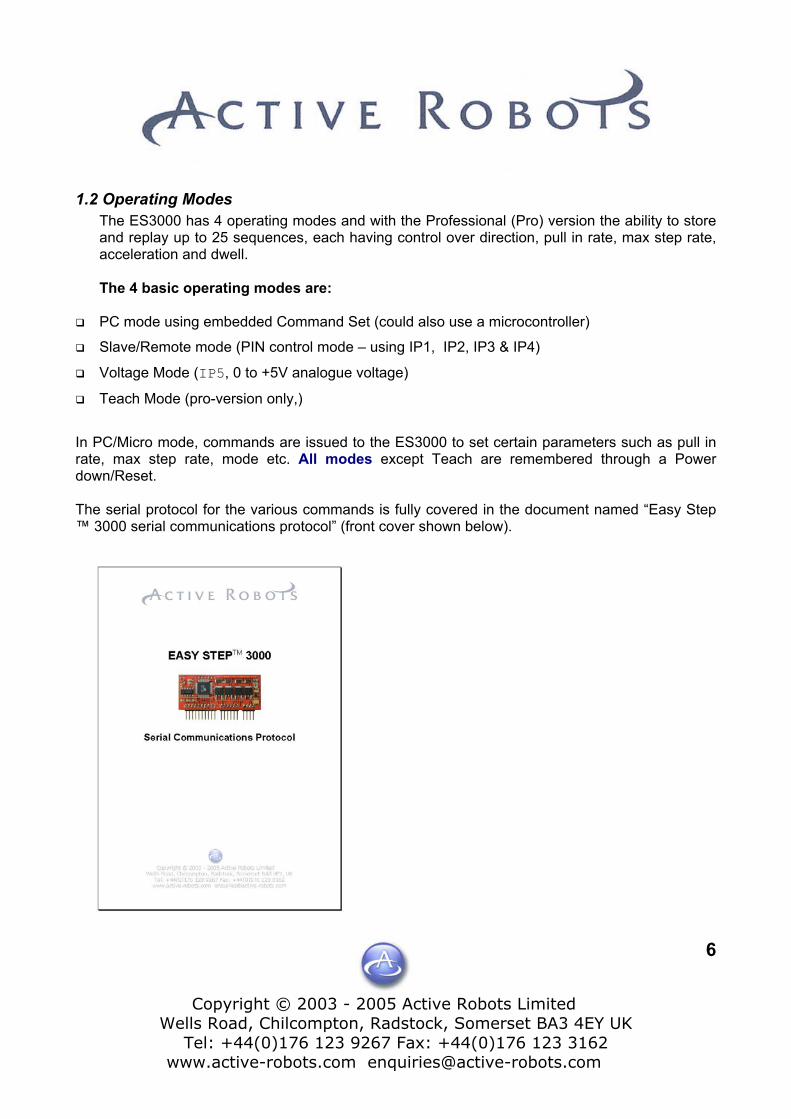
1.2 Operating Modes The ES3000 has 4 operating modes and with the Professional (Pro) version the ability to store and replay up to 25 sequences, each having control over direction, pull in rate, max step rate, acceleration and dwell. The 4 basic operating modes are:
PC mode using embedded Command Set (could also use a microcontroller)
Slave/Remote mode (PIN control mode – using IP1, IP2, IP3 & IP4)
Voltage Mode (IP5, 0 to +5V analogue voltage)
Teach Mode (pro-version only,)
In PC/Micro mode, commands are issued to the ES3000 to set certain parameters such as pull in rate, max step rate, mode etc. All modes except Teach are remembered through a Power down/Reset. The serial protocol for the various commands is fully covered in the document named “Easy Step ™ 3000 serial communications protocol” (front cover shown below).

Copyright © 2003 - 2005 Active Robots Limited
Wells Road, Chilcompton, Radstock, Somerset BA3 4EY UK Tel: +44(0)176 123 9267 Fax: +44(0)176 123 3162
www.active-robots.com [email protected]
7
1.3 Hints and tips – Common problems
1.3.1 Continuous holding torque It’s OK to leave the motor power on in the stop state for long periods. The PCB is fitted with a suitable heatsink.
1.3.2 Logic Supply Voltage The logic Supply for the ES3000 is a minimum of 6Vdc, and no more than 20Vdc. The unit may appear to function correctly with lower voltages but several obscure problems arise if it’s too low.
1.3.3 Documents Please take some time to read this manual before launching off and plugging things together.
1.3.4 Step Rates You may find that steps are being lost or the motor stalls, there are several reasons for this, the most common is that the step rate is too high for the motor, large stepper motors have very low step rates (Forcing resistors can be used to increase the step rate of the motor). If you are using a very small motor (i.e. Sanyo 103-4902-0650) then you may find that the start step rate needs to be increased, many small motors do not function properly at slow step rates, if you need to step slowly with a small motor then try using ‘half step’. The latest version of the PC program; Easy Step ™ ISP 1V29, has in the main splash screen, a tab that allows you to choose a motor type (Setup > Select motor type>). Six popular types are available and once selected the default start and step rates are automatically altered (in PC and Teach mode) to match the motor characteristics. Maximum step rates can be manually calculated as follows: A motor has the following characteristics: 1.8º /step (or 200 steps per revolution), 3.3 Ohm phase resistance and a phase inductance of 3.4uH. To calculate the maximum step rate, assuming we have a need for 85% motor torque and given that 2 Time constants = 85% torque Two Time constant in ms = 2 * (3.4/3.3) = 2.06ms per step Max step rate = 1S / 2.06ms = 485 steps per second

Copyright © 2003 - 2005 Active Robots Limited
Wells Road, Chilcompton, Radstock, Somerset BA3 4EY UK Tel: +44(0)176 123 9267 Fax: +44(0)176 123 3162
www.active-robots.com [email protected]
8
1.3.5 Pro-mode replay using IP3 and IP4 Both these inputs replay stored sequences (programmed in Teach mode), IP3 replays all the memory in one go, IP4 replays it one sequence at a time. Imagine you have 10 sequences stored in memory and you have been working your way through them using the IP4 pin and you are now at sequence number 8 (with only two more to go), at this point IP3 is triggered and all ten sequences automatically replay (starting at 1 not 9), what happens when IP4 is next triggered? It will start from 1 and not carry on from 9. With the above in mind we recommend that you use only one of the replay options on a particular application as using both together is not the design intention.
1.3.6 Industrial Interface - ES3K IND INT An Industrial interface is available from Active Robots for the Easy Step™ this makes connecting wires easy and also adds a whole range of safety features. This allows the unit to be operated in a commercial/factory setting reliably (the spec. is on Active Robots web site). Have a look at the industrial interface user guide, there are some useful circuit diagrams there.
1.3.7 Stepper Motor development system - ES3KDS A stepper motor development system has been designed primarily for educational purposes but is suitable for the hobbyist too. The development system has many features (air cooling, switch mode PSU, square wave oscillator etc) it’s best to have a read through the ES3KDS user guide to get an overview. The ES3KDS also makes an ideal tool to test and determine a motors inherent characteristics. The user guide also contains several circuit diagrams, including one for a switched mode power supply.

Copyright © 2003 - 2005 Active Robots Limited
Wells Road, Chilcompton, Radstock, Somerset BA3 4EY UK Tel: +44(0)176 123 9267 Fax: +44(0)176 123 3162
www.active-robots.com [email protected]
9
2 EASY STEP ™ 3000 Pin Out Data
Fig. 1 Easy Step™ 3000 - PCB and Pin Names
Copyright © 2003 - 2005 Active Robots Limited
Wells Road, Chilcompton, Radstock, Somerset BA3 4EY UK Tel: +44(0)176 123 9267 Fax: +44(0)176 123 3162
www.active-robots.com [email protected]
10
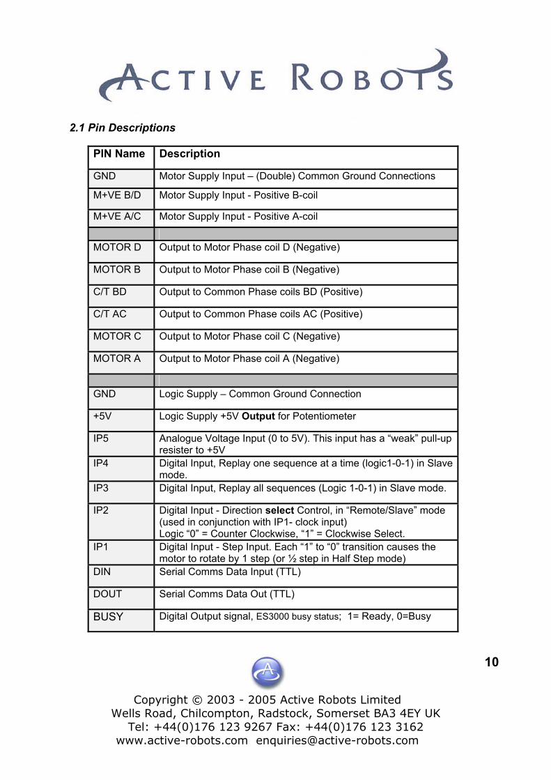
2.1 Pin Descriptions
PIN Name Description
GND Motor Supply Input – (Double) Common Ground Connections
M+VE B/D Motor Supply Input - Positive B-coil
M+VE A/C Motor Supply Input - Positive A-coil
MOTOR D Output to Motor Phase coil D (Negative)
MOTOR B Output to Motor Phase coil B (Negative)
C/T BD Output to Common Phase coils BD (Positive)
C/T AC Output to Common Phase coils AC (Positive)
MOTOR C Output to Motor Phase coil C (Negative)
MOTOR A Output to Motor Phase coil A (Negative)
GND Logic Supply – Common Ground Connection
+5V Logic Supply +5V Output for Potentiometer
IP5 Analogue Voltage Input (0 to 5V). This input has a “weak” pull-up resister to +5V
IP4 Digital Input, Replay one sequence at a time (logic1-0-1) in Slave mode.
IP3 Digital Input, Replay all sequences (Logic 1-0-1) in Slave mode.
IP2 Digital Input - Direction select Control, in “Remote/Slave” mode (used in conjunction with IP1- clock input) Logic “0” = Counter Clockwise, “1” = Clockwise Select.
IP1 Digital Input - Step Input. Each “1” to “0” transition causes the motor to rotate by 1 step (or ½ step in Half Step mode)
DIN Serial Comms Data Input (TTL)
DOUT Serial Comms Data Out (TTL)
BUSY Digital Output signal, ES3000 busy status; 1= Ready, 0=Busy
CopyrighWells Road, C
Tel: +44(www.active-
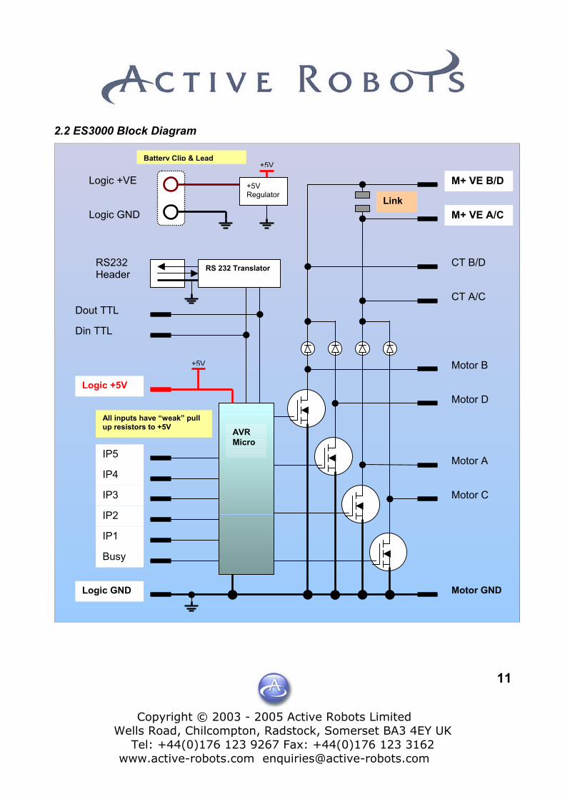
2.2 ES3000 Block Diagram
Busy
All inputs have “weak” up resistors to +5V
RS 232 TranslatorRS232 Header
IP5
IP4
IP3
IP2
IP1
+5V Regulator
Motor B
CT A/C
CT B/D
M+ VE A/C
M+ VE B/D
Link
Dout TTL
Din TTL
Logic +5V
Logic GND
Logic GND
Logic +VE
+5V
t © 2003 - hilcompton
0)176 123 9robots.com
pull
AVRMicro
+5V
Battery Clip & Lead2005 Active Robots Limited , Radstock, Somerset BA3 4EY UK 267 Fax: +44(0)176 123 3162 [email protected]
11
Motor GND
Motor C
Motor A
Motor D
Copyright © 2003 - 2005 Active Robots Limited
Wells Road, Chilcompton, Radstock, Somerset BA3 4EY UK Tel: +44(0)176 123 9267 Fax: +44(0)176 123 3162
www.active-robots.com [email protected]
12
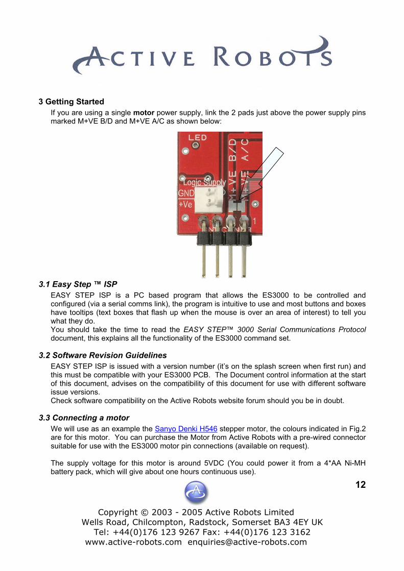
3 Getting Started If you are using a single motor power supply, link the 2 pads just above the power supply pins marked M+VE B/D and M+VE A/C as shown below:
3.1 Easy Step ™ ISP EASY STEP ISP is a PC based program that allows the ES3000 to be controlled and configured (via a serial comms link), the program is intuitive to use and most buttons and boxes have tooltips (text boxes that flash up when the mouse is over an area of interest) to tell you what they do. You should take the time to read the EASY STEP™ 3000 Serial Communications Protocol document, this explains all the functionality of the ES3000 command set.
3.2 Software Revision Guidelines EASY STEP ISP is issued with a version number (it’s on the splash screen when first run) and this must be compatible with your ES3000 PCB. The Document control information at the start of this document, advises on the compatibility of this document for use with different software issue versions. Check software compatibility on the Active Robots website forum should you be in doubt.
3.3 Connecting a motor We will use as an example the Sanyo Denki H546 stepper motor, the colours indicated in Fig.2 are for this motor. You can purchase the Motor from Active Robots with a pre-wired connector suitable for use with the ES3000 motor pin connections (available on request). The supply voltage for this motor is around 5VDC (You could power it from a 4*AA Ni-MH battery pack, which will give about one hours continuous use).
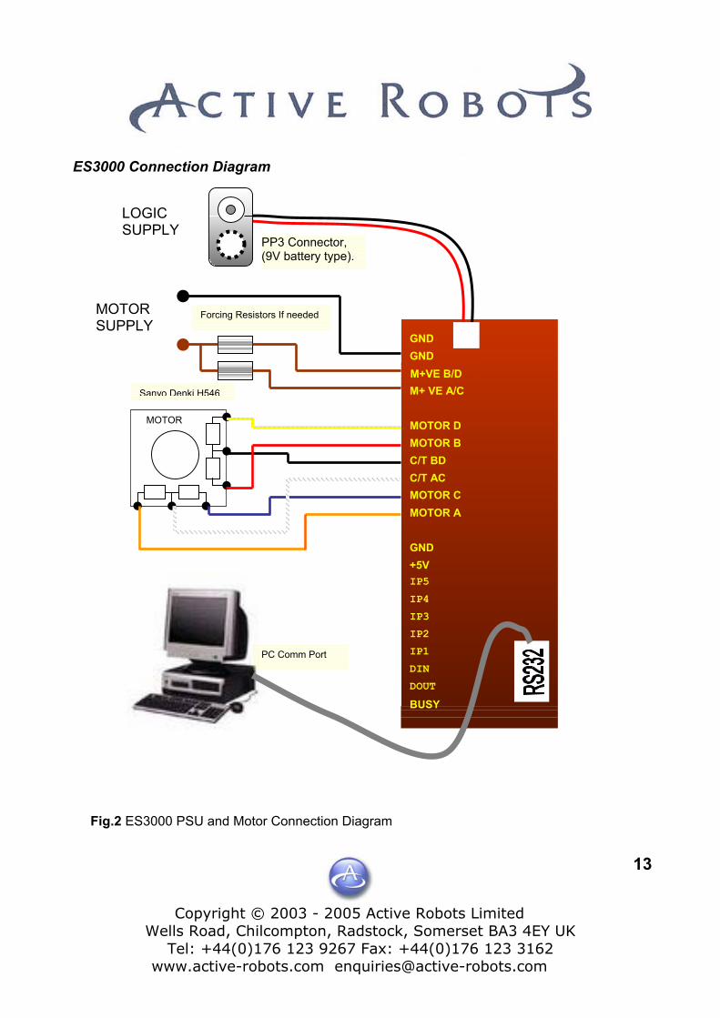
ES3000 Connection Diagram
Forcing Resistors If needed
PP3 Connector, (9V battery type).
MOTOR SUPPLY
M+ VE A/C M+VE B/D GND GND
Fig.2 E
Sanyo Denki H546
LOGIC SUPPLY
Copyright © 2003 - 2005 Active Robots Limited
Wells Road, Chilcompton, Radstock, Somerset BA3 4EY UK Tel: +44(0)176 123 9267 Fax: +44(0)176 123 3162
www.active-robots.com [email protected]
13
MOTOR A MOTOR C C/T AC C/T BD MOTOR B MOTOR D
GND +5V IP5
IP2
IP4
IP3
IP1
DIN
DOUT
BUSY
MOTOR
PC Comm Port
S3000 PSU and Motor Connection Diagram
Copyright © 2003 - 2005 Active Robots Limited
Wells Road, Chilcompton, Radstock, Somerset BA3 4EY UK Tel: +44(0)176 123 9267 Fax: +44(0)176 123 3162
www.active-robots.com [email protected]
14
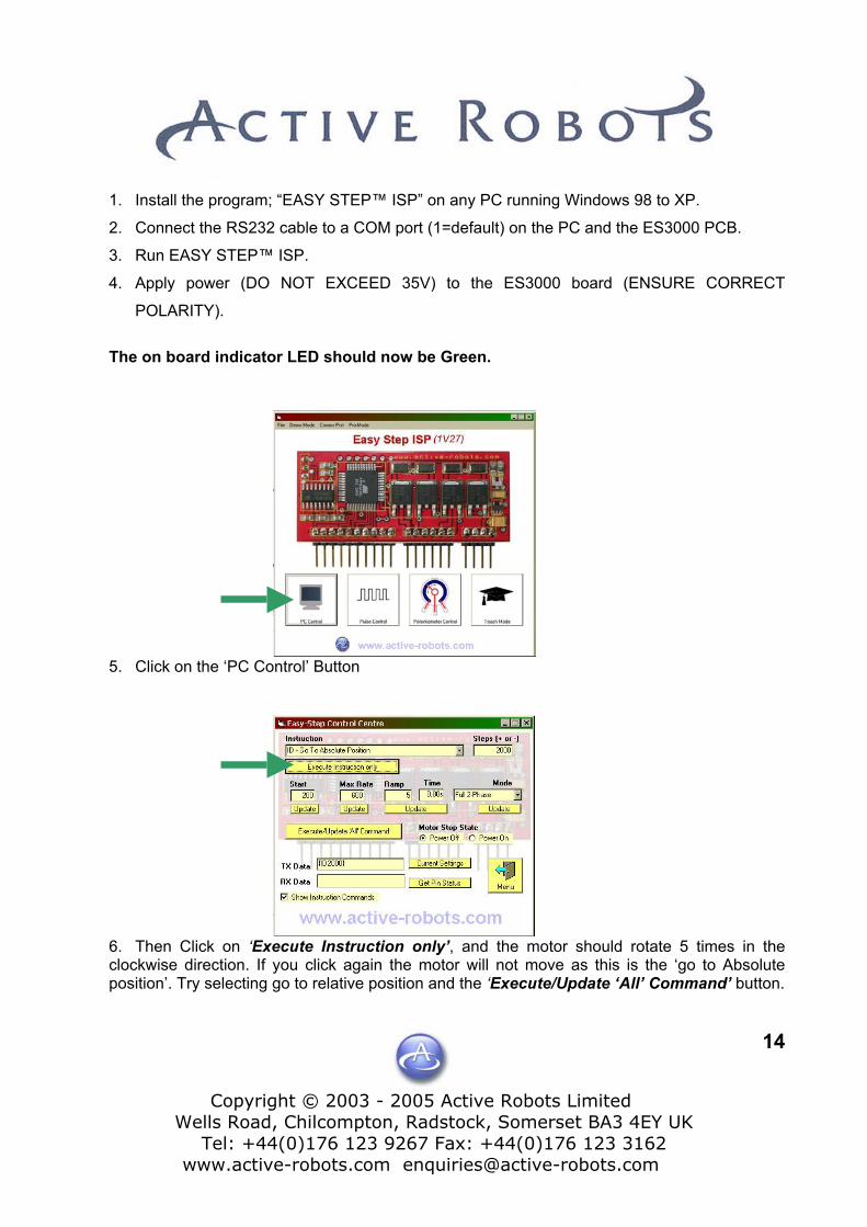
1. Install the program; “EASY STEP™ ISP” on any PC running Windows 98 to XP.
2. Connect the RS232 cable to a COM port (1=default) on the PC and the ES3000 PCB.
3. Run EASY STEP™ ISP.
4. Apply power (DO NOT EXCEED 35V) to the ES3000 board (ENSURE CORRECT
POLARITY).
The on board indicator LED should now be Green.
5. Click on the ‘PC Control’ Button
6. Then Click on ‘Execute Instruction only’, and the motor should rotate 5 times in the clockwise direction. If you click again the motor will not move as this is the ‘go to Absolute position’. Try selecting go to relative position and the ‘Execute/Update ‘All’ Command’ button.

Copyright © 2003 - 2005 Active Robots Limited
Wells Road, Chilcompton, Radstock, Somerset BA3 4EY UK Tel: +44(0)176 123 9267 Fax: +44(0)176 123 3162
www.active-robots.com [email protected]
15
4 Stepper Motor Basics In order to understand the operation of the ES3000 you need to know the basics of stepper motors. This section is a useful reference.
4.1 Step Angle Motor Data sheets state the ‘Step Angle’ of a motor, our example motor has a step angle of 1.8º / Step. This means to achieve one rotation would require; 360º/1.8º = 200 steps
4.2 Step Rate If we had a Step Rate of 600 then for our motor (1.8º step angle) this would mean; 600/200 = 3 revolutions per second
4.3 Step Sequence The ES3000 is designed to drive Unipolar motors, these have 4 coils. The coils age grouped in pairs, often referred to as ‘A’ and ‘B’, thus they are commonly called - 2 Phase Motors.
However if we were to look at terminals ‘A’ and ‘A/C Com’ these are also referred to as a phase coil – although in fact they are half the total winding.
A Unipolar MOTOR
A/C Com Where a motor spec. sheet says for example 3.3Ohm and 3.4uH (for our motor) this is regarding this coil section only i.e. A to A/C Com and not from A to C.
C
B D To make a stepper motor rotate these coils have to be powered in a set sequence. B/D Com There are several sequences available for a
Unipolar motor and these are; Full step 2-phase, Full step 1-phase (sometimes called Wave mode) and Half step. As the names suggest Full step means stepping at the specified Step Angle (see 4.1), Half step means stepping at half the Step angle, or for our motor this means 400 steps per revolution (that means a doubling the stepping resolution). It is possible to ‘Micro step’ this means multiplying the motor resolution by some factor (typically of 128 or more), thus phenomenal rotational positional accuracy is possible, however micro-stepping is not available on the ES3000 product, but is available on higher models.

Copyright © 2003 - 2005 Active Robots Limited
Wells Road, Chilcompton, Radstock, Somerset BA3 4EY UK Tel: +44(0)176 123 9267 Fax: +44(0)176 123 3162
www.active-robots.com [email protected]
16
4.3.1 Full Step 2 Phase, Sequence (CW- Clock Wise motion)
Sequence Number
A B C D
1 1 1 0 0 2 0 1 1 0 3 0 0 1 1 4 1 0 0 1
4.3.2 Full Step 1 Phase (Wave Mode), Sequence (CW- Clock Wise motion) Sequence Number
A B C D
1 1 0 0 0 2 0 1 0 0
3 0 0 1 0 4 0 0 0 1
4.3.3 Half Step, sequence (CW – Clock wise) Sequence Number
A B C D
1 1 0 0 0 2 1 1 0 0 3 0 1 0 0 4 0 1 1 0 5 0 0 1 0 6 0 0 1 1 7 0 0 0 1 8 1 0 0 1
4.3.4 Counter Clockwise (CCW)
If the step sequence of the above truth tables are reversed (i.e. starting from 4 [or 8 in half step] running down to 1) then the motor will run in reverse – or counter clockwise (viewed from the front of the motor).
Copyright © 2003 - 2005 Active Robots Limited
Wells Road, Chilcompton, Radstock, Somerset BA3 4EY UK Tel: +44(0)176 123 9267 Fax: +44(0)176 123 3162
www.active-robots.com [email protected]
17
4.4 Holding Torque Holding torque (or static torque) is the torque with the motor at rest being supplied with the rated current (our example motor has a holding torque of 0.37Nm at 1.2A phase current).
4.5 Detent Torque Is the torque with the motor at rest but with no current flowing.
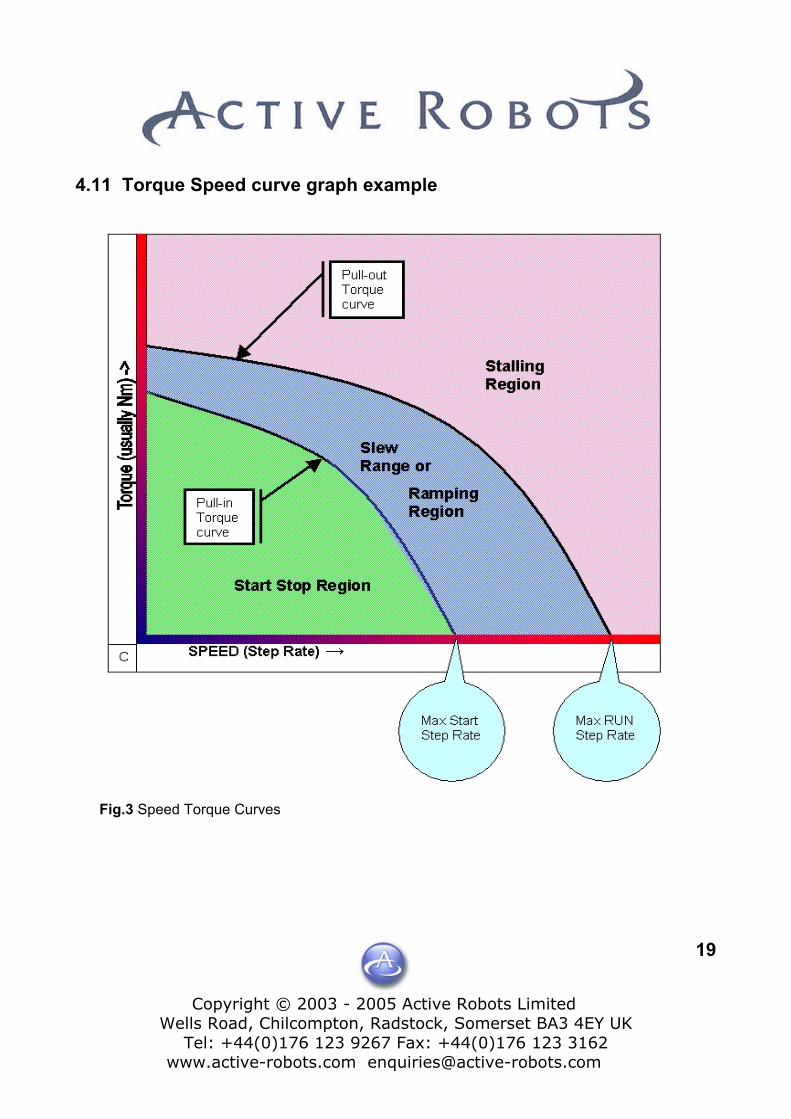
4.6 Pull-in torque Curve This is the speed (step rate) a motor can start, stop or reverse and still stay in synchronisation with motor drive pulses with a given load, greater loads require lower start step rates. Motor manufacturers may supply a graph of this property. If synchronisation is lost then the motor will not be able reach its assigned position, and there will be no way to know how far it has rotated without using some form of rotational sensing feedback (i.e. limit switches).
4.7 Start Stop region This is the region under the Pull-in Torque curve where a motor can be started/stopped or reversed at will. Even so there are certain small areas where the motor is unstartable/unrotatable – the motor manufacturer will highlight these in their Torque-Speed curve charts.
4.8 Pull-out Torque This is the boundary for motors maximum speed for a given load. Beyond this and the motor will stall or loose synchronisation.
4.9 Slew-range This is the area between Pull-in and Pull-out torque, where the motor must be ramped up slowly. Typically a motor is started in the ‘Start Stop region’ and then ramped up to near the ‘Pull-out’ torque limit. If the motor is ramped too quickly then inertia may cause loss of synchronisation.

CopyriWells Road
Tel: +4www.acti
4.10 Forcing Resistors Are used to increase the maximum available step rate for a given motor. Below is an example of how to calculate the value resistor you need for a 12V Supply, we will use our example 1.2A/Phase 3.3Ohms/Phase (The ES3000 has separate power supply inputs unipolar phase coils, so two forcing resistors will be needed)
V Resistor MOTOR
Controller
OV a. Calculate motor Voltag b. Calculate V across R1 c. Calculate R1 = (12V - 4 d. Calculate R2 = R1 = 6. e. Calculate Wattage for R f. Practical Value 6.8 Ohmyou could go as low as 4
+Vsupply
ght © 2003 -, Chilcompto4(0)176 123 ve-robots.com
R1
A
R2
e; V Motor = 1.2A
= V Supply - V
V) / 1.2A = 6.6
6 Ohms
1 = (8V * 1.2) / 2
s (6R8). ActuallOhms. Active rob
B/D
V SupplyV Motor
D
A/C
C
B2n, 92
*
Mo
Oh
=
y aots
005 Active Robots Limited Radstock, Somerset BA3 4EY UK 67 Fax: +44(0)176 123 3162 [email protected]
18
3.3Ohms = 4V
tor = 8V
ms
4.8 Watts (also same for R2)
motor can be driven to 140% of its rated current so supply a 5R4 resistor for this motor.
Copyright © 2003 - 2005 Active Robots Limited
Wells Road, Chilcompton, Radstock, Somerset BA3 4EY UK Tel: +44(0)176 123 9267 Fax: +44(0)176 123 3162
www.active-robots.com [email protected]
19
4.11 Torque Speed curve graph example Fig.3 Speed Torque Curves

Copyright © 2003 - 2005 Active Robots Limited
Wells Road, Chilcompton, Radstock, Somerset BA3 4EY UK Tel: +44(0)176 123 9267 Fax: +44(0)176 123 3162
www.active-robots.com [email protected]
20
5 Easy Step™ ISP - Terminology Summary
5.1 Absolute Position When the ES3000 is first switched on the resting state of the motor becomes the absolute position zero. Absolute position zero is the Home position. Move Absolute will move to a position that is the number of steps specified from the home position. The ES3000 remembers every step made and keeps adding or subtracting as necessary from its internal counter - Current position register +/- 100,000,000,000 steps. It is possible to read this register if needed, by issuing a {CU} command –see ES3000 command and protocol document.
5.2 Home Position When you change the home position after the motor has moved, then this becomes the new home position also absolute position zero changes too. In fact goto absolute position zero and goto home position do the same thing.
5.3 Mark Position This works like a second home position. There is no relationship between the absolute position counter and mark position.
5.4 Inputs as Stops This refers to hardware input pins IP1 and IP2, these are ‘weak’ pulled to +5V (technically referred to as; Normally High), if you connect them to GND (through a switch for example) then the onboard microcontroller on the ES3000 will see this and action it (there are 5 pin command actions available on the ES3000).
Copyright © 2003 - 2005 Active Robots Limited
Wells Road, Chilcompton, Radstock, Somerset BA3 4EY UK Tel: +44(0)176 123 9267 Fax: +44(0)176 123 3162
www.active-robots.com [email protected]
21
6 Easy Step™ 3000 – Basic Operation
6.1 Move Absolute Move Absolute will move to a position that is the number of steps specified from the home position, this move instruction can be issued with or without stops based on pin conditions.
6.2 Move Relative Move Relative, always moves the specified number of steps relative to the current position, but maintains the position register allowing Absolute, Home and Mark position moves to be accurate and consistent.
6.3 Mark Position The ability to set a mark position allows 2 ‘end’ positions to be set which can be moved to by the issuing of a single command, all Absolute move commands operate on the Home position even if the last move you made was to the Mark position; Relative move will always just be relative to your current position.
6.4 Full to Half step positional Integrity Changing modes from Full Step 2-phase to Full Step 1-phase mode will have no effect on the position registers, however, if you change from full to half or back again, in order to maintain positional accuracy, the software will double the number of steps from the home location when changing to half step mode as twice as many steps are now required to return to the home position. When changing back to full step mode the reverse is carried out and the current position register halved, before changing modes, to maintain positional accuracy completely, it is necessary to ensure the number of steps is an even number or else one half step will be lost (0.9 degrees with a 200 step motor). It’s best to decide what mode you are going to use (half or full), and stick to that.
6.5 Move Commands & Acceleration The Pull in Rate, Max Step Rate and Ramp Factors are constantly used values, unless you change them, previously stored rates will be applied to all move commands. If the number of steps to allow full acceleration/deceleration to take place are not available then at the mid point of the move instruction the acceleration will change to deceleration, the motor stopping at the correct location.

Copyright © 2003 - 2005 Active Robots Limited
Wells Road, Chilcompton, Radstock, Somerset BA3 4EY UK Tel: +44(0)176 123 9267 Fax: +44(0)176 123 3162
www.active-robots.com [email protected]
22
6.5 Move Commands – affect of Pin inputs If using the pin commands in PC mode, where movement is stopped by taking one of the hardware control pins low (IP1 and IP2 are used for pin control in PC mode only), then, when the pin goes low, the motor will start decelerating, so it is important if setting the home or mark positions to keep the pull in rate, max step rate and acceleration time low to allow the motor to stop quickly. i.e. in the ‘start stop’ region – see the green part of the speed/torque graph in figure three, Page19.
6.6 Ramp Factor The ramp factor is one of the variable factors within a formula that is used to calculate acceleration and deceleration of the motor. The higher the number the longer the acceleration/deceleration times will be. Start Step Rate and Step Speed settings are also factors that affect timings.
Start Speed Step Speed Ramp Factor Acceleration Time (Secs)
100 500 0 2s 100 500 1 2.8s 100 500 5 5.5s 100 500 10 9s
200 600 0 0.5s 200 600 10 2.5s 200 600 50 10s 200 600 100 18s
Ramp Factor chart It should be noted that a high ramp factor causes very slow acceleration, this can cause the number of steps to “run out” before full speed is reached and thus the motor will slow down again without reaching full speed. Say for example you only wanted to move two hundred steps (1 rotation with 1.8º motor) but the ramp factor meant an acceleration/deceleration time of 20seconds then the motor would hardly increase above the start step rate. The ‘Easy Step 3000 ISP TM ’ program displays the deceleration time in a box next to the Ramp Factor entry box.
Copyright © 2003 - 2005 Active Robots Limited
Wells Road, Chilcompton, Radstock, Somerset BA3 4EY UK Tel: +44(0)176 123 9267 Fax: +44(0)176 123 3162
www.active-robots.com [email protected]
23
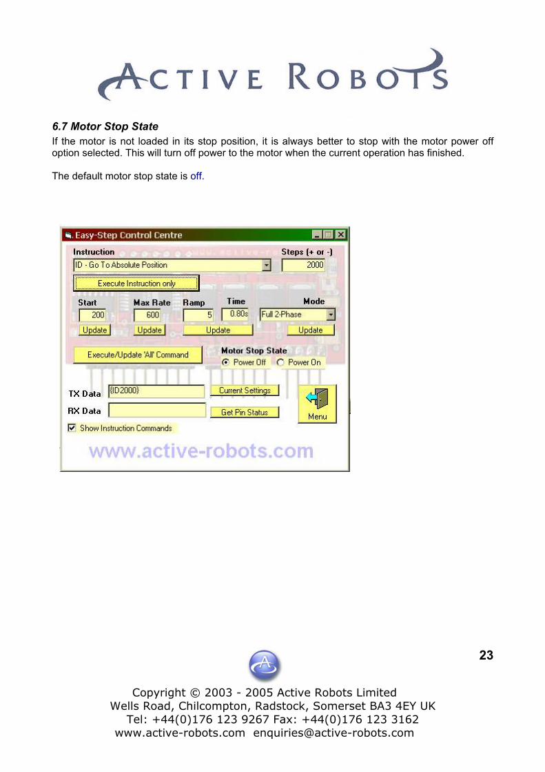
6.7 Motor Stop State If the motor is not loaded in its stop position, it is always better to stop with the motor power off option selected. This will turn off power to the motor when the current operation has finished. The default motor stop state is off.

Copyright © 2003 - 2005 Active Robots Limited
Wells Road, Chilcompton, Radstock, Somerset BA3 4EY UK Tel: +44(0)176 123 9267 Fax: +44(0)176 123 3162
www.active-robots.com [email protected]
24
7 PC Mode/Pin Controls Pin control is used in conjunction with the serial interface control program ‘ES3000 ISP’. You can run this program on your PC and issue the Pin Commands (you need to have the ES3000 connected to a serial port on your computer and be in PC mode. The program has options to change the comms port if Comm-1 is not available. First Click on the PC Mode Control The Easy-Step Control Centre then opens.
Click on this drop down options box to reveal the Inputs options, the (Px) commands
Copyright © 2003 - 2005 Active Robots Limited
Wells Road, Chilcompton, Radstock, Somerset BA3 4EY UK Tel: +44(0)176 123 9267 Fax: +44(0)176 123 3162
www.active-robots.com [email protected]
25
7.1 Pin Control Options Five options are available, these are; 1. {PF} Goto Absolute Position with inputs 1 and 2 as stops
2. {PG} Goto Relative Position with inputs 1 and 2 as stops
3. {PH} Go Clockwise until Input 2
4. {PJ} Go Anti-clockwise until Input 1 and Zero Position Counter
5. {PK} Go Clockwise until Input 2 and mark position
7.2 Pin Control Example By way of example, try using no.4 - {PJ} Go Anti-clockwise until Input 1 and Zero Position Counter. You will need to connect a flying wire to the common ground (any of the GND pins). Go in to the easy step control centre screen and select the option PJ…, then click on the ‘execute/Update all commands’ button. At this point the motor should start and continue rotating CCW (counter clockwise). Now take the flying wire and touch IP1 and the motor should stop. Also note that the home position has changed, so this new position has now become the new ‘absolute position zero’ or home position.

Copyright © 2003 - 2005 Active Robots
Wells Road, Chilcompton, Radstock, SomersTel: +44(0)176 123 9267 Fax: +44(0)17
www.active-robots.com enquiries@active-r
8 Remote/Slave Mode
+5V
D
S
PP3 Connector (9V battery type)
LS
R
0V GND
0V
0V
+5V
+5V
0V
Fig. 4 Remote/Slave or Pulse Mode Connection diagram This mode is selected by clicking on In remote/slave mode the ES3000 accepts commands on the IP1 selected this mode is remembered through a power down/Reset.
MOTOR AMOTOR C
C/T C/T MO TOR BMOTOR DM+ VE M+VE
e6
GND
GND
GN +5V IP5IP2
IP4
IP3IP1
DIN DOUT BUSYMOTOR SUPPLY
anyo Denki H546
OGIC UPPLY
Clock – Step Signal
Close for CCW or Open for Clockwis
Replay ALL
eplay one sequence at a time
Busy Output (1=ready, 0=Busy)
Limited t BA3 4EY UK 123 3162
obots.com
26
IP2 IP3 and IP4 pins. Once
Copyright © 2003 - 2005 Active Robots Limited
Wells Road, Chilcompton, Radstock, Somerset BA3 4EY UK Tel: +44(0)176 123 9267 Fax: +44(0)176 123 3162
www.active-robots.com [email protected]
27
8.1 Comms during Slave mode It is also possible to still send serial information, however, transmitting serial information when stepping (depending on step rate and length of instruction) may cause the Easy Step to delay a step. Under normal operating circumstances, it is best to only issue exit remote/slave mode commands. The busy signal output pin could be monitored to determine when the ES3000 has finished moving the motor, the convention is; 1= Ready, 0=Busy (where 1=5V and 0=0V)
8.2 Slave mode IP1 & IP2 - Clock-step waveform Applying a pulse (1-0-1, where 1=5V and 0=0V) to IP1 will cause the easy Step to increment the position counter and step the motor once, clockwise if IP2 is High, Counter clockwise if low. This mode is very useful if you want to control the stepper motor from another Micro allowing a simple single pulse to step the motor. In order for the pulses to be detected they must be at least 100uS (or 10KHz square wave) and symmetrical. Non symmetrical waveforms are acceptable as long as the times between negative edges are at least 100uS. In practice stepper motors are limited to about 1KHz which is well within the limits of the ES3000. NOTE IP1 and IP2 can also be used as pin controls when replaying (using IP3 and IP4), for example you could replay the stored command ‘Go Clockwise Until IP2’ , IP2 will now work as a stop when pulled low, it will then return to its normal function (CW/CCW control).
8.3 Slave Mode IP1 & IP2 - Motor stop state The LED on the ES3000 board will be Red when in remote/slave mode.
8.4 Slave Mode IP3 & IP4 – Replay Stored teach mode commands When the ES3000 has learnt sequences in teach mode then these sequences can be replayed by software command or by toggling (logic 1-0-1; the 1-0 edge triggers the action) input pins IP3 and IP4. IP3 replays the entire replay memory (up to 25 stored command sequences). IP4 replays the sequences one at a time, the time between each is determined by how often IP4 is toggled. Both IP3 and IP4 use a wrap around system, so that once the last command is reached then the process repeats again – starting with the first stored command again. We recommend that you only use one of these (IP3/4) controls in your application see section 1.3.5

Copyright © 2003 - 2005 Active Robots Lim
Wells Road, Chilcompton, Radstock, SomersetTel: +44(0)176 123 9267 Fax: +44(0)176
www.active-robots.com enquiries@active-rob
9 Voltage Mode
D
Sanyo Denki H546
PP3 Connector
Potentiometer is 10K, linear, carbon type.
Fig.5 Potentiometer control connection diagram To select Voltage mode click on this button In voltage mode, the input voltage on IP5 is measured. If you are goingown circuit it is important not to exceed the Logic Supply (+5V) as peto the ES3000.
MOTOR AMOTOR C
C/T C/T MO TOR BMOTOR DM+ VE M+VE
1
GND
GND
GN +5V IP5IP2
IP4
IP3 IP1 DIN DOUT BUSYMOTOR SUPPLY
LOGIC SUPPLY
ited BA3 4EY UK 23 3162 ots.com
28
to supply a voltage via your rmanent damage may occur

Copyright © 2003 - 2005 Active Robots Limited
Wells Road, Chilcompton, Radstock, Somerset BA3 4EY UK Tel: +44(0)176 123 9267 Fax: +44(0)176 123 3162
www.active-robots.com [email protected]
29
9.1 Voltage Modes There are 3 voltage modes which can be selected in ES3000 ISP.
Mode 1 The analogue voltage is used to mimic a potentiometer movement, i.e. the motor will turn through approximately 270 degrees following the movement of a potentiometer connected to IP5, +VE and ground (assuming a standard potentiometer is used).
Mode 2 The motor will mimic the movements of a potentiometer but with much greater movement, the rotation of the pot will be amplified allowing about 3 turns of the motor for 270 degrees of pot movement.
Mode 3 Allows for continuous rotation of the motor in either direction with a centre off point. If the pot is in mid track the motor will be stationary, moving away from the centre point will cause the motor to start turning, the further from the centre point the greater the motor speed. 5V = maximum CCW speed 2.5V = at rest 0V = maximum CW speed Notes on ES3000 Reset All Voltage type modes will use the ‘Maximum Step rate’ and motor ‘stop state’ setup in PC mode; however after a Power up/down cycle the ES3000 will revert back to factory default settings, the motor stop state will be ‘power off’ and the maximum step speed will be 400 (this was chosen to give accurate tracking of a standard potentiometer being rotated manually). General Advice Rotating a pot quickly with a heavily loaded motor attached and a high maximum step rate may cause loss of position. If long leads are being used to connect the ES3000 to your potentiometer you may find a 10V 22uF capacitor between GND and the centre wiper will help reduce interference.
Copyright © 2003 - 2005 Active Robots Limited
Wells Road, Chilcompton, Radstock, Somerset BA3 4EY UK Tel: +44(0)176 123 9267 Fax: +44(0)176 123 3162
www.active-robots.com [email protected]
30
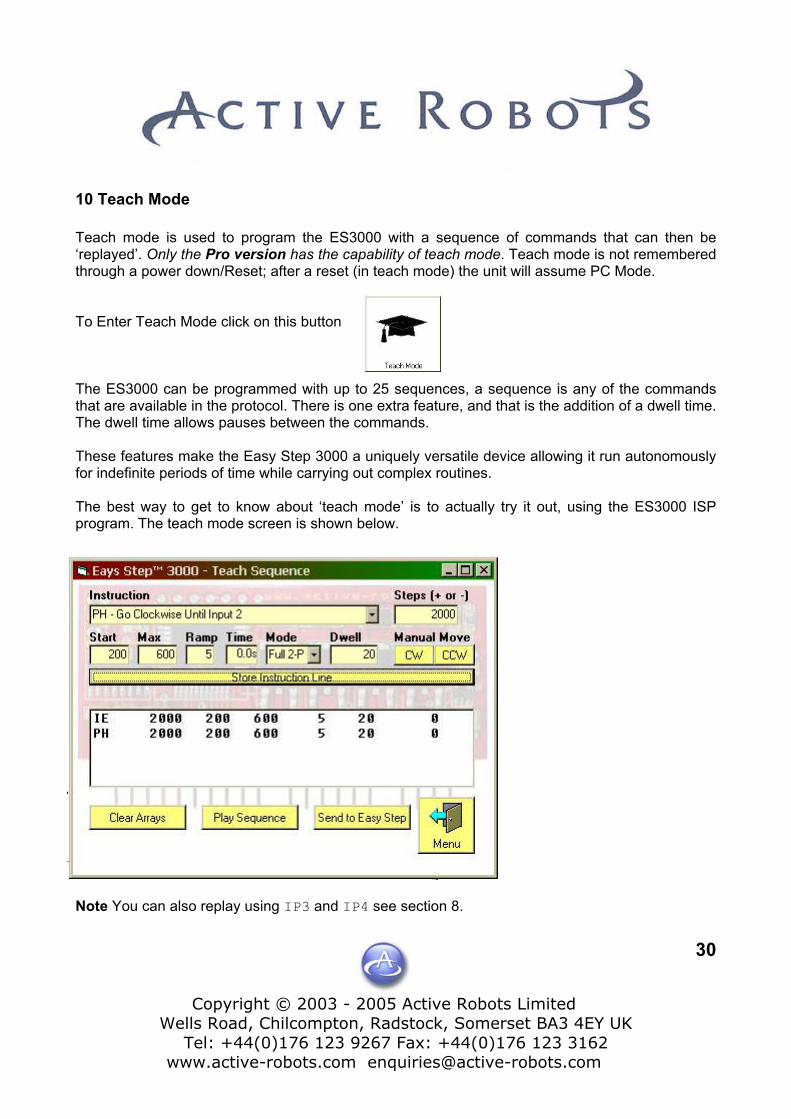
10 Teach Mode Teach mode is used to program the ES3000 with a sequence of commands that can then be ‘replayed’. Only the Pro version has the capability of teach mode. Teach mode is not remembered through a power down/Reset; after a reset (in teach mode) the unit will assume PC Mode. To Enter Teach Mode click on this button The ES3000 can be programmed with up to 25 sequences, a sequence is any of the commands that are available in the protocol. There is one extra feature, and that is the addition of a dwell time. The dwell time allows pauses between the commands. These features make the Easy Step 3000 a uniquely versatile device allowing it run autonomously for indefinite periods of time while carrying out complex routines. The best way to get to know about ‘teach mode’ is to actually try it out, using the ES3000 ISP program. The teach mode screen is shown below.
Note You can also replay using IP3 and IP4 see section 8.
Copyright © 2003 - 2005 Active Robots Limited
Wells Road, Chilcompton, Radstock, Somerset BA3 4EY UK Tel: +44(0)176 123 9267 Fax: +44(0)176 123 3162
www.active-robots.com [email protected]
31
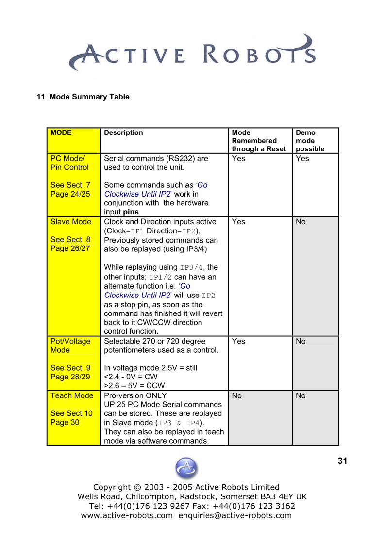
11 Mode Summary Table
MODE Description Mode Remembered through a Reset
Demo mode possible
PC Mode/ Pin Control See Sect. 7 Page 24/25
Serial commands (RS232) are used to control the unit. Some commands such as ‘Go Clockwise Until IP2’ work in conjunction with the hardware input pins
Yes Yes
Slave Mode See Sect. 8 Page 26/27
Clock and Direction inputs active (Clock=IP1 Direction=IP2). Previously stored commands can also be replayed (using IP3/4) While replaying using IP3/4, the other inputs; IP1/2 can have an alternate function i.e. ’Go Clockwise Until IP2’ will use IP2 as a stop pin, as soon as the command has finished it will revert back to it CW/CCW direction control function.
Yes No
Pot/Voltage Mode See Sect. 9 Page 28/29
Selectable 270 or 720 degree potentiometers used as a control. In voltage mode 2.5V = still <2.4 - 0V = CW >2.6 – 5V = CCW
Yes No
Teach Mode See Sect.10 Page 30
Pro-version ONLY UP 25 PC Mode Serial commands can be stored. These are replayed in Slave mode (IP3 & IP4). They can also be replayed in teach mode via software commands.
No No

Copyright © 2003 - 2005 Active Robo
Wells Road, Chilcompton, Radstock, SomTel: +44(0)176 123 9267 Fax: +44(0
www.active-robots.com enquiries@activ
12 Circuit – Input protection and filter Below is shown a simple protection circuit for use with IP1 through to IP5 and the Busy O/P. Although simple it does give good protection against the human error that occurs when connecting up circuit boards! One circuit is shown, duplicate as needed. ES3000 Board
Resistor
1K2
INPUT ¼ Watt
Capacitor50V
100nF
To: IPx
ts Limited erset BA3 4EY UK )176 123 3162 e-robots.com
32
GND
Copyright © 2003 - 2005 Active Robots Limited
Wells Road, Chilcompton, Radstock, Somerset BA3 4EY UK Tel: +44(0)176 123 9267 Fax: +44(0)176 123 3162
www.active-robots.com [email protected]
33
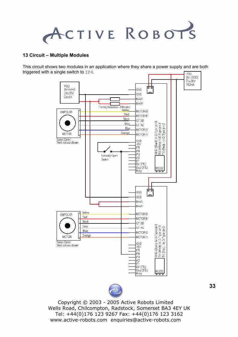
13 Circuit – Multiple Modules This circuit shows two modules in an application where they share a power supply and are both triggered with a single switch to IP4.

Copyright © 2003 - 2005 Active Robots Limited
Wells Road, Chilcompton, Radstock, Somerset BA3 4EY UK Tel: +44(0)176 123 9267 Fax: +44(0)176 123 3162
www.active-robots.com [email protected]
34
NOTES END OF DOCUMENT.