easylink feature white paper (hmm) - Тиском · huawei e9000 server v100r001 easylink feature...
TRANSCRIPT
Huawei E9000 Server V100R001
easyLink Feature White Paper (HMM)
Issue 02
Date 2017-03-31
HUAWEI TECHNOLOGIES CO., LTD.
Issue 02 (2017-03-31) Huawei Proprietary and Confidential
Copyright © Huawei Technologies Co., Ltd.
i
Copyright © Huawei Technologies Co., Ltd. 2017. All rights reserved.
No part of this document may be reproduced or transmitted in any form or by any means without prior
written consent of Huawei Technologies Co., Ltd.
Trademarks and Permissions
and other Huawei trademarks are trademarks of Huawei Technologies Co., Ltd.
All other trademarks and trade names mentioned in this document are the property of their respective
holders.
Notice
The purchased products, services and features are stipulated by the contract made between Huawei and
the customer. All or part of the products, services and features described in this document may not be
within the purchase scope or the usage scope. Unless otherwise specified in the contract, all statements,
information, and recommendations in this document are provided "AS IS" without warranties, guarantees or
representations of any kind, either express or implied.
The information in this document is subject to change without notice. Every effort has been made in the
preparation of this document to ensure accuracy of the contents, but all statements, information, and
recommendations in this document do not constitute a warranty of any kind, express or implied.
Huawei Technologies Co., Ltd.
Address: Huawei Industrial Base
Bantian, Longgang
Shenzhen 518129
People's Republic of China
Website: http://www.huawei.com
Email: [email protected]
Huawei E9000 Server
easyLink Feature White Paper (HMM) Contents
Issue 02 (2017-03-31) Huawei Proprietary and Confidential
Copyright © Huawei Technologies Co., Ltd.
ii
Contents
1 E9000 easyLink Feature Description ......................................................................................... 1
1.1 Background Information ............................................................................................................................................... 1
1.2 Working Principle and Related Concepts ..................................................................................................................... 3
1.3 E9000 easyLink Reliability Assurance ......................................................................................................................... 9
1.4 VLAN Tags ................................................................................................................................................................. 11
1.5 FC Configuration ........................................................................................................................................................ 12
1.6 Hardware Requirements ............................................................................................................................................. 13
2 Configuring E9000 easyLink ..................................................................................................... 14
2.1 Configuration Procedure ............................................................................................................................................. 14
2.2 Service Configuration Instances ................................................................................................................................. 28
2.2.1 Stacked Networking (1) ........................................................................................................................................... 28
2.2.2 FCoE Networking (2) .............................................................................................................................................. 30
2.2.3 FCoE Networking (3) .............................................................................................................................................. 32
2.2.3.1 FCF Application Scenario ..................................................................................................................................... 32
2.2.3.2 Networking Requirements .................................................................................................................................... 33
2.2.3.3 Physical Networking Description ......................................................................................................................... 34
2.2.3.4 easyLink Configuration Procedure ....................................................................................................................... 34
2.2.3.5 NIC Configuration in the OS ................................................................................................................................ 42
2.2.4 FCoE Networking (4) .............................................................................................................................................. 42
2.2.4.1 NPV Application Scenario .................................................................................................................................... 42
2.2.4.2 Networking Requirements .................................................................................................................................... 43
2.2.4.3 Physical Networking Description ......................................................................................................................... 43
2.2.4.4 easyLink Configuration Procedure ....................................................................................................................... 44
2.2.4.5 NIC Configuration in the OS ................................................................................................................................ 52
A Acronyms and Abbreviations .................................................................................................. 53

Huawei E9000 Server
easyLink Feature White Paper (HMM) 1 E9000 easyLink Feature Description
Issue 02 (2017-03-31) Huawei Proprietary and Confidential
Copyright © Huawei Technologies Co., Ltd.
1
1 E9000 easyLink Feature Description
1.1 Background Information
1.2 Working Principle and Related Concepts
1.3 E9000 easyLink Reliability Assurance
1.4 VLAN Tags
1.5 FC Configuration
1.6 Hardware Requirements
1.1 Background Information
With the development of services, the scale of data centers becomes larger, network
converged, and networking more complex. A flat network will prevail in the future. A
chassis-type blade server has switch modules installed in its chassis, that is, a switching layer
is added to the network. How to reduce networking complexity?
As a chassis-type blade server, the E9000 server has switch modules installed in its chassis
and connections exist between compute nodes, compute node NICs (mezzanine cards), and
switch modules. It is more complex to configure a service network because a user has to
understand connections between each compute node NIC and switch modules, configurations
between switch modules, and connections between switch modules in chassis and external
switches.
The E9000 easyLink feature allows compute nodes in the chassis to serve as a combination of
servers running virtual services and switch modules to serve as server NICs. Therefore, not
only is a flat network achieved (networking of switch modules in the chassis and external
switches is simplified.), but also internal switch configuration can be completed automatically
to simplify internal network management and configuration because a user can ignore
physical connections between compute nodes and the switch modules in the chassis by setting
service belonging of the compute node NICs.
Figure 1-1 shows connections between E9000 mezzanine cards and switch modules.

Huawei E9000 Server
easyLink Feature White Paper (HMM) 1 E9000 easyLink Feature Description
Issue 02 (2017-03-31) Huawei Proprietary and Confidential
Copyright © Huawei Technologies Co., Ltd.
2
Figure 1-1 Connections between mezzanine cards and switch modules
Figure 1-2 shows an easyLink service model.
Figure 1-2 easyLink service model
Compute nodes in the E9000 chassis are divided into different computing resource pools. The
computing resource pools that provide the same services communicate with each other
through the same business VLAN. Each business VLAN serves as a service NIC that
communicates with external switches using uplink ports on the business VLAN. In easyLink
configuration, associate compute nodes with business VLANs to complete the switch
configuration.
Huawei E9000 Server
easyLink Feature White Paper (HMM) 1 E9000 easyLink Feature Description
Issue 02 (2017-03-31) Huawei Proprietary and Confidential
Copyright © Huawei Technologies Co., Ltd.
3
1.2 Working Principle and Related Concepts
The E9000 easyLink feature allows users to use the Hyper Module Management (HMM)
WebUI to perform end-to-end management of the network connecting switch modules in the
chassis to server NICs.
easyLink Management Functions
easyLink management provides switch module configuration and information query:
Switch module configuration consists of switch profile and NIC profile configuration.
Switch Profile Configuration
A switch profile defines the relationships between business types and external switches and
includes the following:
Business VLAN: indicates the type of business data transmitted between the chassis and
external switches.
Uplink: indicates switch module panel ports for business data transmission.
FC configuration: indicates FC SAN connection attributes, including FC mode, FCoE port
DCB, and zone configuration.
NIC Profile Configuration
A NIC profile defines the relationships between physical computing resources and service
types.
NIC profiles are associated with compute nodes and consist of three parts: NIC teaming,
vNICs based on NIC teaming, and relationships between vNICs and business VLANs.
NIC teaming indicates combining NIC ports into a group for redundancy.
vNICs are based on NIC teaming and serve as communication interfaces of compute
nodes in blade servers. Create vNICs for NIC teams based on the service types.
Associate vNICs with business VLANs to complete the association between service
types of compute nodes and those of switch modules.
In this way, computing services on the compute nodes can communicate with external
switches through vNICs. After the preceding configuration, the system will automatically
configure the interfaces between compute nodes and switch modules and form a link that
connects NICs, internal switch modules, and external networks. During the configuration,
users do not need to focus on relationships between switch module ports and compute
nodes.
Figure 1-3 shows the easyLink configuration diagram.
Huawei E9000 Server
easyLink Feature White Paper (HMM) 1 E9000 easyLink Feature Description
Issue 02 (2017-03-31) Huawei Proprietary and Confidential
Copyright © Huawei Technologies Co., Ltd.
4
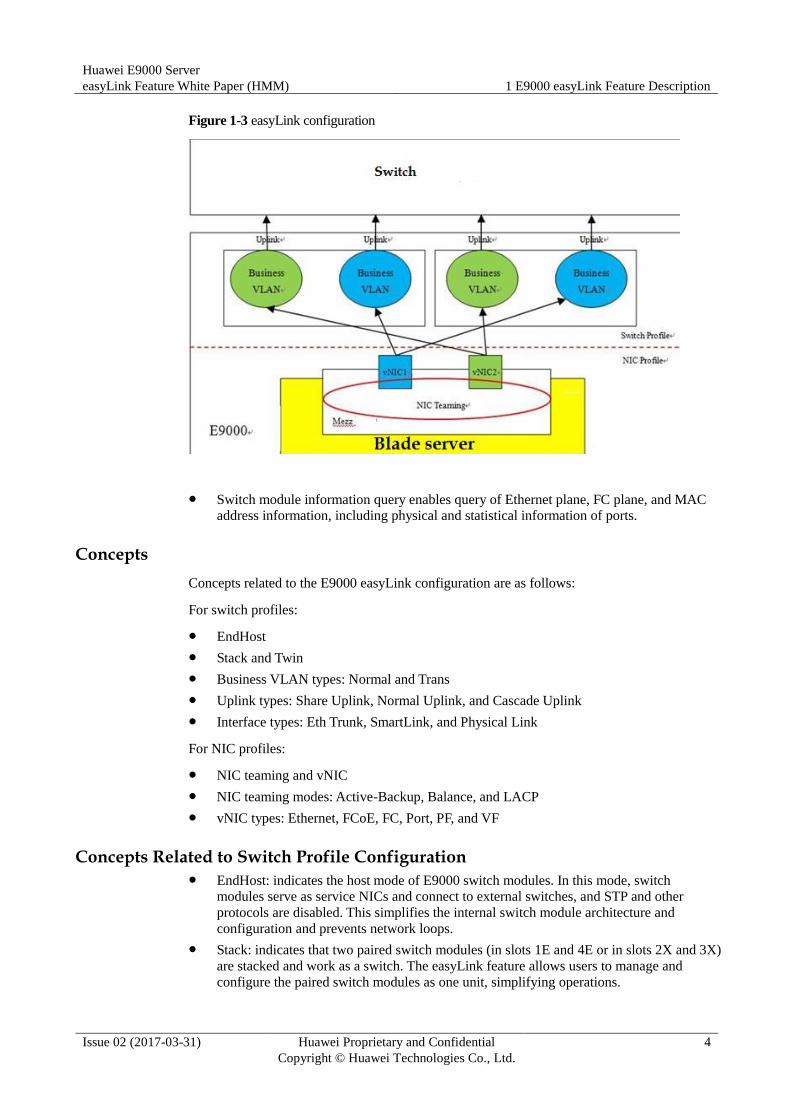
Figure 1-3 easyLink configuration
Switch module information query enables query of Ethernet plane, FC plane, and MAC
address information, including physical and statistical information of ports.
Concepts
Concepts related to the E9000 easyLink configuration are as follows:
For switch profiles:
EndHost
Stack and Twin
Business VLAN types: Normal and Trans
Uplink types: Share Uplink, Normal Uplink, and Cascade Uplink
Interface types: Eth Trunk, SmartLink, and Physical Link
For NIC profiles:
NIC teaming and vNIC
NIC teaming modes: Active-Backup, Balance, and LACP
vNIC types: Ethernet, FCoE, FC, Port, PF, and VF
Concepts Related to Switch Profile Configuration EndHost: indicates the host mode of E9000 switch modules. In this mode, switch
modules serve as service NICs and connect to external switches, and STP and other
protocols are disabled. This simplifies the internal switch module architecture and
configuration and prevents network loops.
Stack: indicates that two paired switch modules (in slots 1E and 4E or in slots 2X and 3X)
are stacked and work as a switch. The easyLink feature allows users to manage and
configure the paired switch modules as one unit, simplifying operations.
Huawei E9000 Server
easyLink Feature White Paper (HMM) 1 E9000 easyLink Feature Description
Issue 02 (2017-03-31) Huawei Proprietary and Confidential
Copyright © Huawei Technologies Co., Ltd.
5
Twin: indicates that two switch modules are not stacked, but they have the same service
configuration (except switch module management information), so that dual planes are
provided for the service network for backup.
Business VLAN: indicates a bearer that carries services on switch modules. Specify
VLAN IDs for business VLANs and the IDs range from 2 to 4063. Business VLANs
include Trans VLANs and normal VLANs. Multiple business VLANs can be created, but
duplicate VLAN IDs are not allowed. When multiple VLAN IDs are required for data
transmission, use a Trans VLAN. If only one VLAN ID is required, use a normal VLAN.
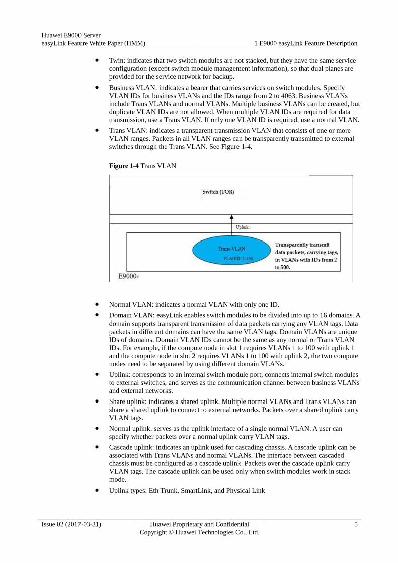
Trans VLAN: indicates a transparent transmission VLAN that consists of one or more
VLAN ranges. Packets in all VLAN ranges can be transparently transmitted to external
switches through the Trans VLAN. See Figure 1-4.
Figure 1-4 Trans VLAN
Normal VLAN: indicates a normal VLAN with only one ID.
Domain VLAN: easyLink enables switch modules to be divided into up to 16 domains. A
domain supports transparent transmission of data packets carrying any VLAN tags. Data
packets in different domains can have the same VLAN tags. Domain VLANs are unique
IDs of domains. Domain VLAN IDs cannot be the same as any normal or Trans VLAN
IDs. For example, if the compute node in slot 1 requires VLANs 1 to 100 with uplink 1
and the compute node in slot 2 requires VLANs 1 to 100 with uplink 2, the two compute
nodes need to be separated by using different domain VLANs.
Uplink: corresponds to an internal switch module port, connects internal switch modules
to external switches, and serves as the communication channel between business VLANs
and external networks.
Share uplink: indicates a shared uplink. Multiple normal VLANs and Trans VLANs can
share a shared uplink to connect to external networks. Packets over a shared uplink carry
VLAN tags.
Normal uplink: serves as the uplink interface of a single normal VLAN. A user can
specify whether packets over a normal uplink carry VLAN tags.
Cascade uplink: indicates an uplink used for cascading chassis. A cascade uplink can be
associated with Trans VLANs and normal VLANs. The interface between cascaded
chassis must be configured as a cascade uplink. Packets over the cascade uplink carry
VLAN tags. The cascade uplink can be used only when switch modules work in stack
mode.
Uplink types: Eth Trunk, SmartLink, and Physical Link
Huawei E9000 Server
easyLink Feature White Paper (HMM) 1 E9000 easyLink Feature Description
Issue 02 (2017-03-31) Huawei Proprietary and Confidential
Copyright © Huawei Technologies Co., Ltd.
6
Eth Trunk: indicates an Ethernet trunk, which is a logical interface formed by bonding
multiple physical ports. Traffic is shared among active physical ports based on MAC
addresses, which increases bandwidth and provides port redundancy.
SmartLink: consists of an active link and a standby link, both of which can be Ethernet
trunks. In active/standby mode, the active link is activated and the standby link does not
forward traffic. When the active link is faulty, traffic is switched over to the standby link.
The SmartLink feature requires external switches, which must be Huawei switches.
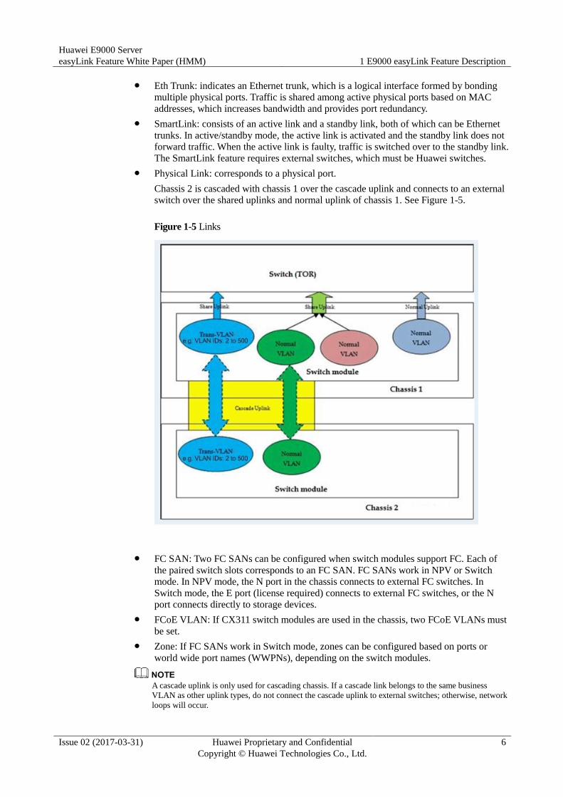
Physical Link: corresponds to a physical port.
Chassis 2 is cascaded with chassis 1 over the cascade uplink and connects to an external
switch over the shared uplinks and normal uplink of chassis 1. See Figure 1-5.
Figure 1-5 Links
FC SAN: Two FC SANs can be configured when switch modules support FC. Each of
the paired switch slots corresponds to an FC SAN. FC SANs work in NPV or Switch
mode. In NPV mode, the N port in the chassis connects to external FC switches. In
Switch mode, the E port (license required) connects to external FC switches, or the N
port connects directly to storage devices.
FCoE VLAN: If CX311 switch modules are used in the chassis, two FCoE VLANs must
be set.
Zone: If FC SANs work in Switch mode, zones can be configured based on ports or
world wide port names (WWPNs), depending on the switch modules.
A cascade uplink is only used for cascading chassis. If a cascade link belongs to the same business
VLAN as other uplink types, do not connect the cascade uplink to external switches; otherwise, network
loops will occur.
Huawei E9000 Server
easyLink Feature White Paper (HMM) 1 E9000 easyLink Feature Description
Issue 02 (2017-03-31) Huawei Proprietary and Confidential
Copyright © Huawei Technologies Co., Ltd.
7
NIC Profile NIC teaming: Multiple physical ports are bonded together to improve bandwidth and
provide link redundancy.
NIC teaming modes: Active-Backup, Balance, and LACP
Active-Backup: indicates that physical NIC ports in a bond work in active/standby mode.
Balance: indicates the Ethernet trunk mode. Physical NIC ports in a bond form a static
Ethernet trunk. Data packets are shared among healthy NIC ports.
LACP: indicates the static LACP mode of the Ethernet trunk. LACP is used between
NIC ports and switch modules.
If UMC or FCoE is enabled on the NIC, LACP mode is not supported.
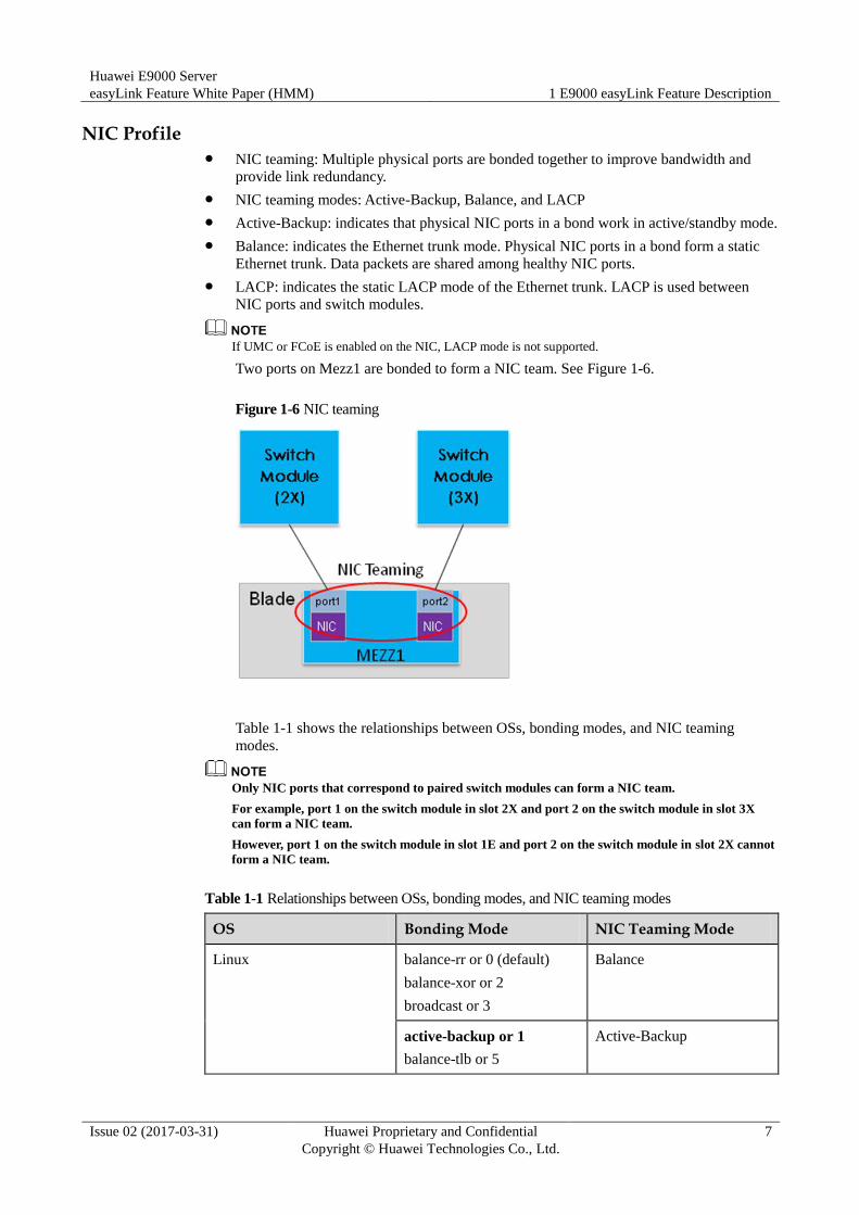
Two ports on Mezz1 are bonded to form a NIC team. See Figure 1-6.
Figure 1-6 NIC teaming
Table 1-1 shows the relationships between OSs, bonding modes, and NIC teaming
modes.
Only NIC ports that correspond to paired switch modules can form a NIC team.
For example, port 1 on the switch module in slot 2X and port 2 on the switch module in slot 3X
can form a NIC team.
However, port 1 on the switch module in slot 1E and port 2 on the switch module in slot 2X cannot
form a NIC team.
Table 1-1 Relationships between OSs, bonding modes, and NIC teaming modes
OS Bonding Mode NIC Teaming Mode
Linux balance-rr or 0 (default)
balance-xor or 2
broadcast or 3
Balance
active-backup or 1
balance-tlb or 5
Active-Backup
Huawei E9000 Server
easyLink Feature White Paper (HMM) 1 E9000 easyLink Feature Description
Issue 02 (2017-03-31) Huawei Proprietary and Confidential
Copyright © Huawei Technologies Co., Ltd.
8
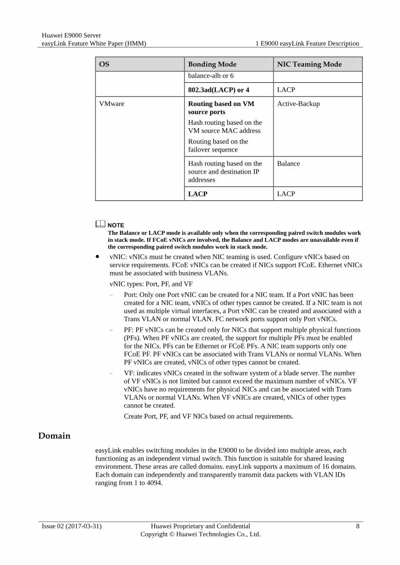
OS Bonding Mode NIC Teaming Mode
balance-alb or 6
802.3ad(LACP) or 4 LACP
VMware Routing based on VM
source ports
Hash routing based on the
VM source MAC address
Routing based on the
failover sequence
Active-Backup
Hash routing based on the
source and destination IP
addresses
Balance
LACP LACP
The Balance or LACP mode is available only when the corresponding paired switch modules work
in stack mode. If FCoE vNICs are involved, the Balance and LACP modes are unavailable even if
the corresponding paired switch modules work in stack mode.
vNIC: vNICs must be created when NIC teaming is used. Configure vNICs based on
service requirements. FCoE vNICs can be created if NICs support FCoE. Ethernet vNICs
must be associated with business VLANs.
vNIC types: Port, PF, and VF
− Port: Only one Port vNIC can be created for a NIC team. If a Port vNIC has been
created for a NIC team, vNICs of other types cannot be created. If a NIC team is not
used as multiple virtual interfaces, a Port vNIC can be created and associated with a
Trans VLAN or normal VLAN. FC network ports support only Port vNICs.
− PF: PF vNICs can be created only for NICs that support multiple physical functions
(PFs). When PF vNICs are created, the support for multiple PFs must be enabled
for the NICs. PFs can be Ethernet or FCoE PFs. A NIC team supports only one
FCoE PF. PF vNICs can be associated with Trans VLANs or normal VLANs. When
PF vNICs are created, vNICs of other types cannot be created.
− VF: indicates vNICs created in the software system of a blade server. The number
of VF vNICs is not limited but cannot exceed the maximum number of vNICs. VF
vNICs have no requirements for physical NICs and can be associated with Trans
VLANs or normal VLANs. When VF vNICs are created, vNICs of other types
cannot be created.
Create Port, PF, and VF NICs based on actual requirements.
Domain
easyLink enables switching modules in the E9000 to be divided into multiple areas, each
functioning as an independent virtual switch. This function is suitable for shared leasing
environment. These areas are called domains. easyLink supports a maximum of 16 domains.
Each domain can independently and transparently transmit data packets with VLAN IDs
ranging from 1 to 4094.
Huawei E9000 Server
easyLink Feature White Paper (HMM) 1 E9000 easyLink Feature Description
Issue 02 (2017-03-31) Huawei Proprietary and Confidential
Copyright © Huawei Technologies Co., Ltd.
9
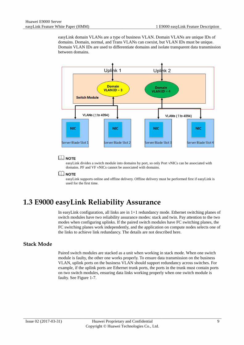
easyLink domain VLANs are a type of business VLAN. Domain VLANs are unique IDs of
domains. Domain, normal, and Trans VLANs can coexist, but VLAN IDs must be unique.
Domain VLAN IDs are used to differentiate domains and isolate transparent data transmission
between domains.
easyLink divides a switch module into domains by port, so only Port vNICs can be associated with
domains. PF and VF vNICs cannot be associated with domains.
easyLink supports online and offline delivery. Offline delivery must be performed first if easyLink is
used for the first time.
1.3 E9000 easyLink Reliability Assurance
In easyLink configuration, all links are in 1+1 redundancy mode. Ethernet switching planes of
switch modules have two reliability assurance modes: stack and twin. Pay attention to the two
modes when configuring uplinks. If the paired switch modules have FC switching planes, the
FC switching planes work independently, and the application on compute nodes selects one of
the links to achieve link redundancy. The details are not described here.
Stack Mode
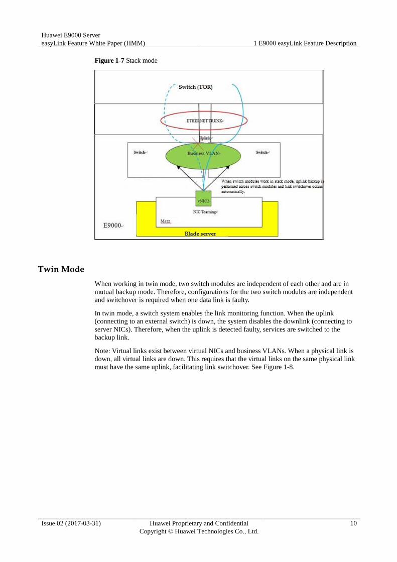
Paired switch modules are stacked as a unit when working in stack mode. When one switch
module is faulty, the other one works properly. To ensure data transmission on the business
VLAN, uplink ports on the business VLAN should support redundancy across switches. For
example, if the uplink ports are Ethernet trunk ports, the ports in the trunk must contain ports
on two switch modules, ensuring data links working properly when one switch module is
faulty. See Figure 1-7.
Huawei E9000 Server
easyLink Feature White Paper (HMM) 1 E9000 easyLink Feature Description
Issue 02 (2017-03-31) Huawei Proprietary and Confidential
Copyright © Huawei Technologies Co., Ltd.
10
Figure 1-7 Stack mode
Twin Mode
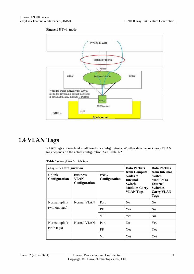
When working in twin mode, two switch modules are independent of each other and are in
mutual backup mode. Therefore, configurations for the two switch modules are independent
and switchover is required when one data link is faulty.
In twin mode, a switch system enables the link monitoring function. When the uplink
(connecting to an external switch) is down, the system disables the downlink (connecting to
server NICs). Therefore, when the uplink is detected faulty, services are switched to the
backup link.
Note: Virtual links exist between virtual NICs and business VLANs. When a physical link is
down, all virtual links are down. This requires that the virtual links on the same physical link
must have the same uplink, facilitating link switchover. See Figure 1-8.
Huawei E9000 Server
easyLink Feature White Paper (HMM) 1 E9000 easyLink Feature Description
Issue 02 (2017-03-31) Huawei Proprietary and Confidential
Copyright © Huawei Technologies Co., Ltd.
11
Figure 1-8 Twin mode
1.4 VLAN Tags
VLAN tags are involved in all easyLink configurations. Whether data packets carry VLAN
tags depends on the actual configuration. See Table 1-2.
Table 1-2 easyLink VLAN tags
easyLink Configuration Data Packets
from Compute
Nodes to
Internal
Switch
Modules Carry
VLAN Tags
Data Packets
from Internal
Switch
Modules to
External
Switches
Carry VLAN
Tags
Uplink
Configuration
Business
VLAN
Configuration
vNIC
Configuration
Normal uplink
(without tags)
Normal VLAN Port No No
PF Yes No
VF Yes No
Normal uplink
(with tags)
Normal VLAN Port No Yes
PF Yes Yes
VF Yes Yes
Huawei E9000 Server
easyLink Feature White Paper (HMM) 1 E9000 easyLink Feature Description
Issue 02 (2017-03-31) Huawei Proprietary and Confidential
Copyright © Huawei Technologies Co., Ltd.
12
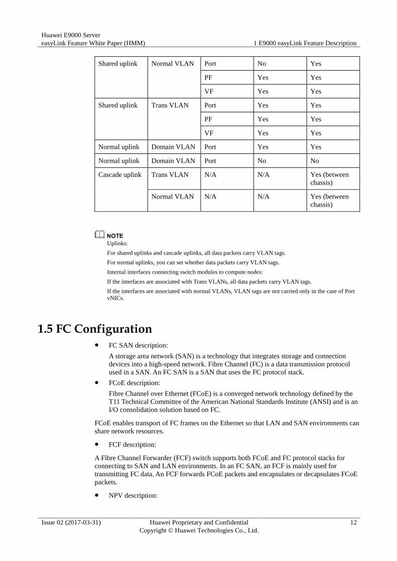
Shared uplink Normal VLAN Port No Yes
PF Yes Yes
VF Yes Yes
Shared uplink Trans VLAN Port Yes Yes
PF Yes Yes
VF Yes Yes
Normal uplink Domain VLAN Port Yes Yes
Normal uplink Domain VLAN Port No No
Cascade uplink Trans VLAN N/A N/A Yes (between
chassis)
Normal VLAN N/A N/A Yes (between
chassis)
Uplinks:
For shared uplinks and cascade uplinks, all data packets carry VLAN tags.
For normal uplinks, you can set whether data packets carry VLAN tags.
Internal interfaces connecting switch modules to compute nodes:
If the interfaces are associated with Trans VLANs, all data packets carry VLAN tags.
If the interfaces are associated with normal VLANs, VLAN tags are not carried only in the case of Port
vNICs.
1.5 FC Configuration FC SAN description:
A storage area network (SAN) is a technology that integrates storage and connection
devices into a high-speed network. Fibre Channel (FC) is a data transmission protocol
used in a SAN. An FC SAN is a SAN that uses the FC protocol stack.
FCoE description:
Fibre Channel over Ethernet (FCoE) is a converged network technology defined by the
T11 Technical Committee of the American National Standards Institute (ANSI) and is an
I/O consolidation solution based on FC.
FCoE enables transport of FC frames on the Ethernet so that LAN and SAN environments can
share network resources.
FCF description:
A Fibre Channel Forwarder (FCF) switch supports both FCoE and FC protocol stacks for
connecting to SAN and LAN environments. In an FC SAN, an FCF is mainly used for
transmitting FC data. An FCF forwards FCoE packets and encapsulates or decapsulates FCoE
packets.
NPV description:
Huawei E9000 Server
easyLink Feature White Paper (HMM) 1 E9000 easyLink Feature Description
Issue 02 (2017-03-31) Huawei Proprietary and Confidential
Copyright © Huawei Technologies Co., Ltd.
13
A SAN has high demands for edge switches directly connected to node devices. N-Port
virtualization (NPV) switches do not occupy domain IDs and enable a SAN to exceed the
limit of 239 edge switches.
Zone description:
In an FCoE network, users can use zones to control access between node devices to improve
network security.
FSB description
An FIP Snooping Bridge (FSB) functions as a bridge in FCF networks. The access switch
serves as an FCoE switch without complete FCF functionality.
1.6 Hardware Requirements
easyLink has no special hardware requirements and supports all E9000 hardware. However,
different features have different requirements:
Version requirements:
− Switch module software version: 2.14 or later
− MM910 version: 5.00 or later (FC configuration requires version 5.09 or later.)
− BMC version: iBMCv1 5.21 or later; iBMCv2 1.62 or later
− FCoE gateway (MX510 FC module on the CX311) firmware version: later than
9.8.1.04.00
Requirements of port splitting and flexible subcards:
− Hardware requirement: CX320 switch module
− MM910 version: 5.75 or later
Huawei E9000 Server
easyLink Feature White Paper (HMM) 2 Configuring E9000 easyLink
Issue 02 (2017-03-31) Huawei Proprietary and Confidential
Copyright © Huawei Technologies Co., Ltd.
14
2 Configuring E9000 easyLink
2.1 Configuration Procedure
2.2 Service Configuration Instances
2.1 Configuration Procedure
The easyLink configuration procedure is as follows:
First, based on service requirements of switch modules in slots 1E, 4E, 2X, and 3X, configure
switch profiles, which include internal business VLANs and uplinks connecting to external
switches. Uplinks are not required for intra-chassis communication.
Second, import NIC information of compute nodes and create NIC profiles. If all slots have
the same compute nodes and mezzanine cards, import the NIC information only once. Bond
NIC ports based on the imported NIC information. Ports in the same group are redundant to
each other. Then create vNICs for NIC teams based on service requirements. vNIC
information includes relationships between vNICs and business VLANs.
Finally, bond NIC profiles to corresponding slots. Restart the switch modules or forcibly
deliver the switch configuration for the configuration to take effect.

Huawei E9000 Server
easyLink Feature White Paper (HMM) 2 Configuring E9000 easyLink
Issue 02 (2017-03-31) Huawei Proprietary and Confidential
Copyright © Huawei Technologies Co., Ltd.
15
Figure 2-1 Configuration guidelines
If an FC storage network is included, FC SAN configuration is required. FC SAN configuration includes
the working mode (NPV/Switch), FCoE VLAN (required for CX311 switch modules), and zoning
(available in Switch mode).
Enabling Switch Centralized Management
Step 1 Enable Switch Centralized Management Configuration.
The corresponding configuration window is displayed. Because the original configuration
page (see Figure 2-3) is invalid, configure the switch module management IP addresses in the
basic information about switch profiles. Figure 2-2 shows the page for enabling centralized
switch management.
Huawei E9000 Server
easyLink Feature White Paper (HMM) 2 Configuring E9000 easyLink
Issue 02 (2017-03-31) Huawei Proprietary and Confidential
Copyright © Huawei Technologies Co., Ltd.
16
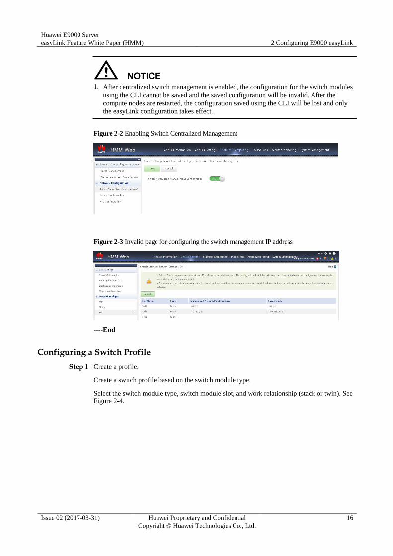
1. After centralized switch management is enabled, the configuration for the switch modules
using the CLI cannot be saved and the saved configuration will be invalid. After the
compute nodes are restarted, the configuration saved using the CLI will be lost and only
the easyLink configuration takes effect.
Figure 2-2 Enabling Switch Centralized Management
Figure 2-3 Invalid page for configuring the switch management IP address
----End
Configuring a Switch Profile
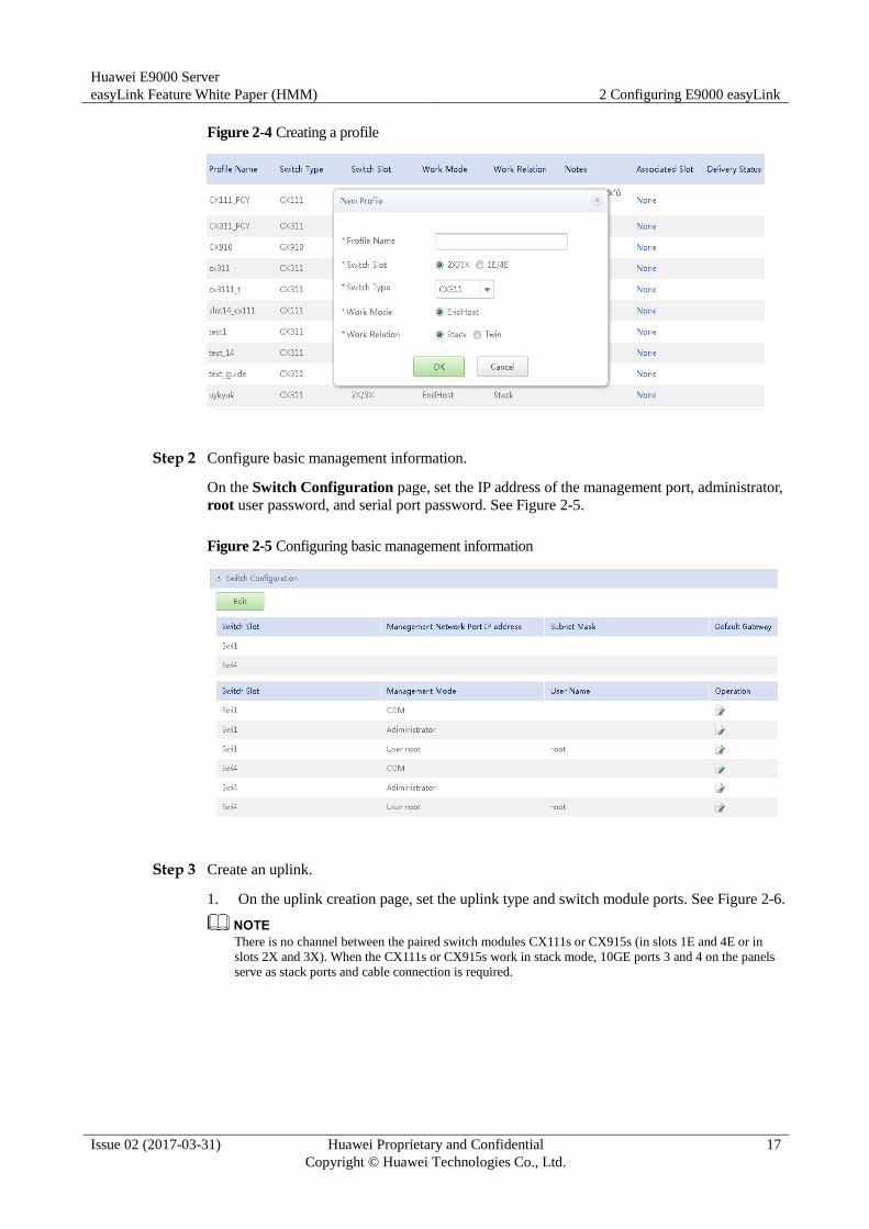
Step 1 Create a profile.
Create a switch profile based on the switch module type.
Select the switch module type, switch module slot, and work relationship (stack or twin). See
Figure 2-4.
Huawei E9000 Server
easyLink Feature White Paper (HMM) 2 Configuring E9000 easyLink
Issue 02 (2017-03-31) Huawei Proprietary and Confidential
Copyright © Huawei Technologies Co., Ltd.
17
Figure 2-4 Creating a profile
Step 2 Configure basic management information.
On the Switch Configuration page, set the IP address of the management port, administrator,
root user password, and serial port password. See Figure 2-5.
Figure 2-5 Configuring basic management information
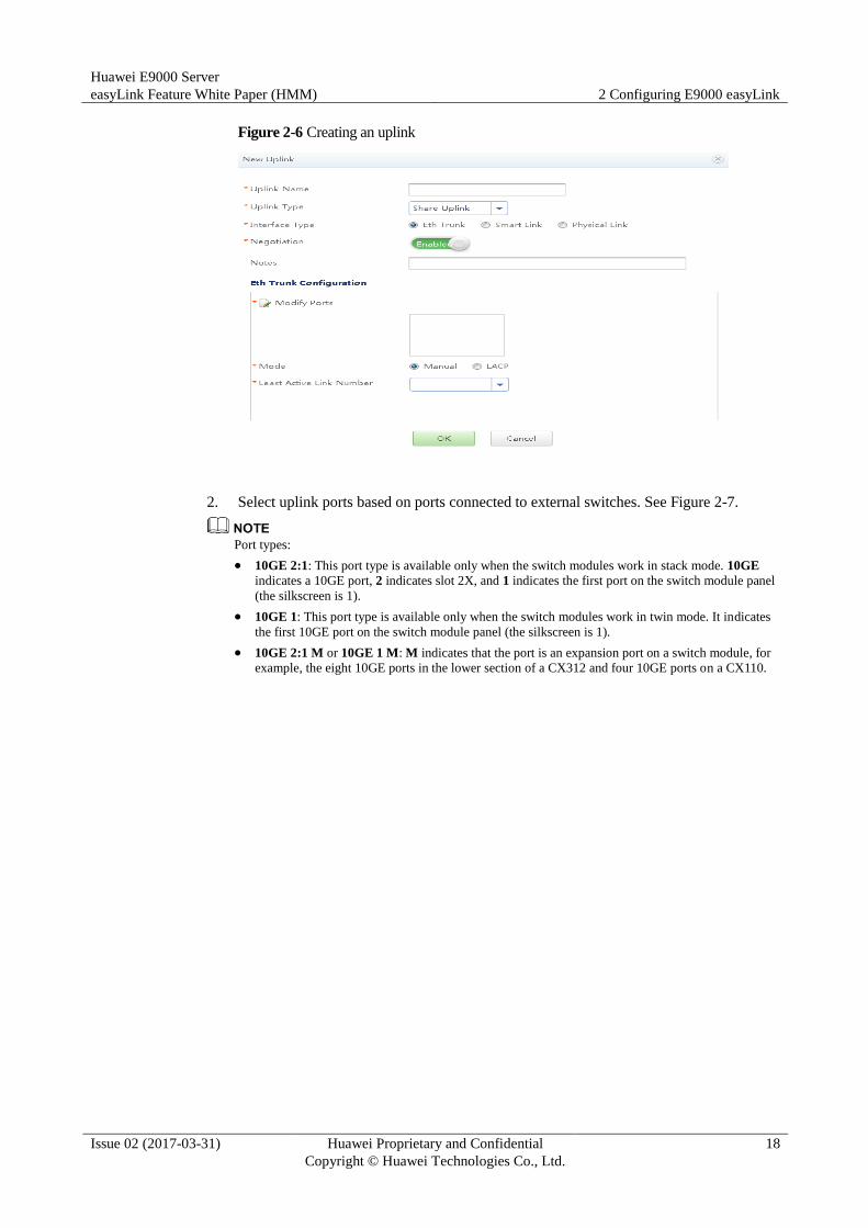
Step 3 Create an uplink.
1. On the uplink creation page, set the uplink type and switch module ports. See Figure 2-6.
There is no channel between the paired switch modules CX111s or CX915s (in slots 1E and 4E or in
slots 2X and 3X). When the CX111s or CX915s work in stack mode, 10GE ports 3 and 4 on the panels
serve as stack ports and cable connection is required.
Huawei E9000 Server
easyLink Feature White Paper (HMM) 2 Configuring E9000 easyLink
Issue 02 (2017-03-31) Huawei Proprietary and Confidential
Copyright © Huawei Technologies Co., Ltd.
18
Figure 2-6 Creating an uplink
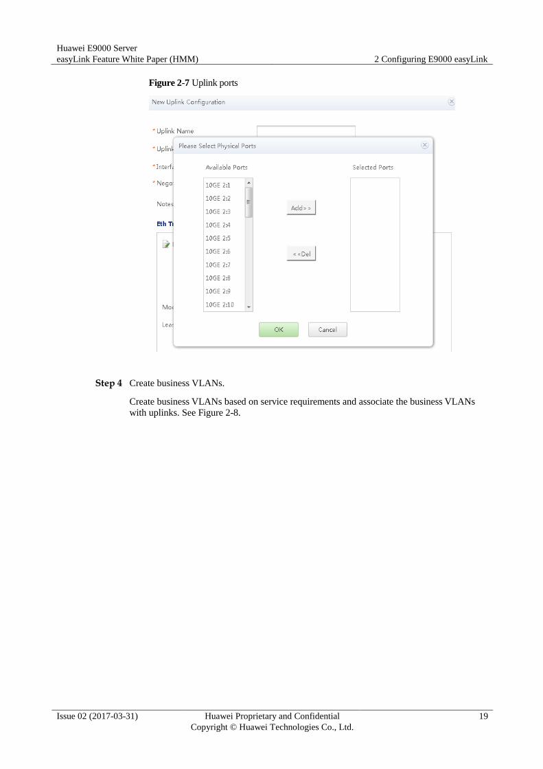
2. Select uplink ports based on ports connected to external switches. See Figure 2-7.
Port types:
10GE 2:1: This port type is available only when the switch modules work in stack mode. 10GE
indicates a 10GE port, 2 indicates slot 2X, and 1 indicates the first port on the switch module panel
(the silkscreen is 1).
10GE 1: This port type is available only when the switch modules work in twin mode. It indicates
the first 10GE port on the switch module panel (the silkscreen is 1).
10GE 2:1 M or 10GE 1 M: M indicates that the port is an expansion port on a switch module, for
example, the eight 10GE ports in the lower section of a CX312 and four 10GE ports on a CX110.
Huawei E9000 Server
easyLink Feature White Paper (HMM) 2 Configuring E9000 easyLink
Issue 02 (2017-03-31) Huawei Proprietary and Confidential
Copyright © Huawei Technologies Co., Ltd.
19
Figure 2-7 Uplink ports
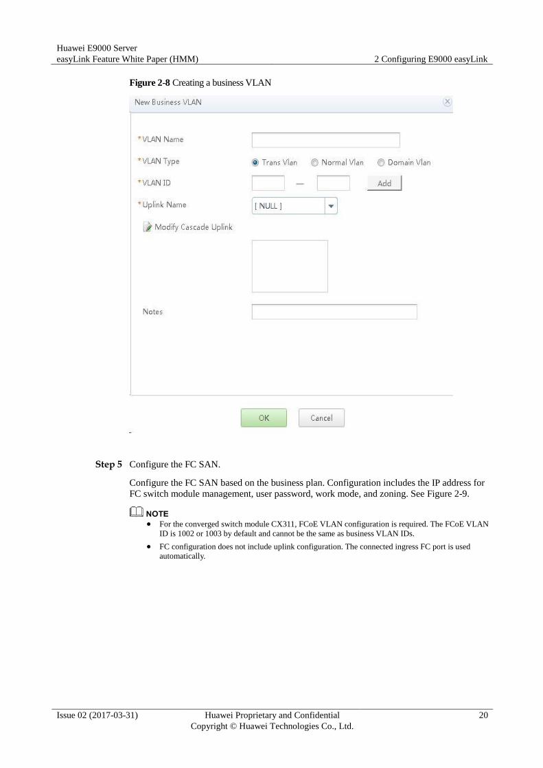
Step 4 Create business VLANs.
Create business VLANs based on service requirements and associate the business VLANs
with uplinks. See Figure 2-8.
Huawei E9000 Server
easyLink Feature White Paper (HMM) 2 Configuring E9000 easyLink
Issue 02 (2017-03-31) Huawei Proprietary and Confidential
Copyright © Huawei Technologies Co., Ltd.
20
Figure 2-8 Creating a business VLAN
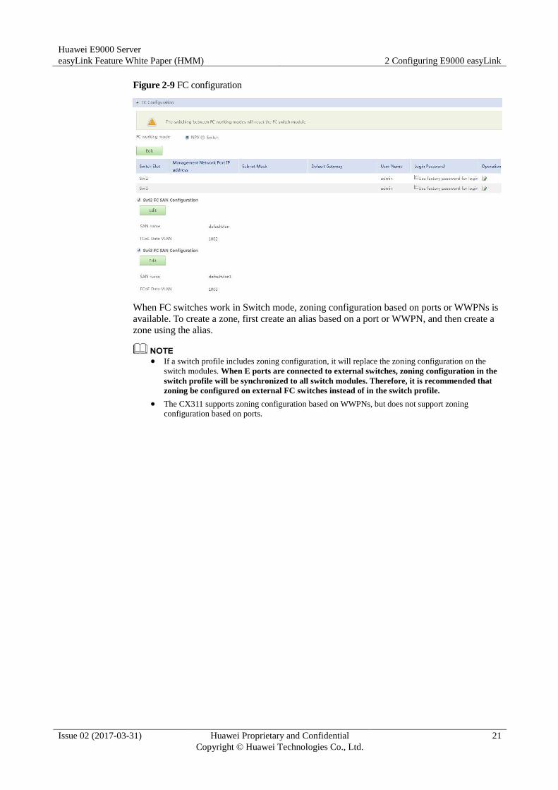
Step 5 Configure the FC SAN.
Configure the FC SAN based on the business plan. Configuration includes the IP address for
FC switch module management, user password, work mode, and zoning. See Figure 2-9.
For the converged switch module CX311, FCoE VLAN configuration is required. The FCoE VLAN
ID is 1002 or 1003 by default and cannot be the same as business VLAN IDs.
FC configuration does not include uplink configuration. The connected ingress FC port is used
automatically.
Huawei E9000 Server
easyLink Feature White Paper (HMM) 2 Configuring E9000 easyLink
Issue 02 (2017-03-31) Huawei Proprietary and Confidential
Copyright © Huawei Technologies Co., Ltd.
21
Figure 2-9 FC configuration
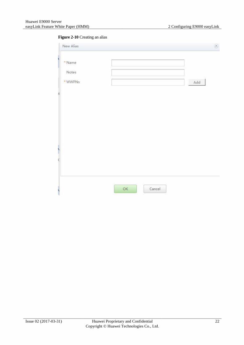
When FC switches work in Switch mode, zoning configuration based on ports or WWPNs is
available. To create a zone, first create an alias based on a port or WWPN, and then create a
zone using the alias.
If a switch profile includes zoning configuration, it will replace the zoning configuration on the
switch modules. When E ports are connected to external switches, zoning configuration in the
switch profile will be synchronized to all switch modules. Therefore, it is recommended that
zoning be configured on external FC switches instead of in the switch profile.
The CX311 supports zoning configuration based on WWPNs, but does not support zoning
configuration based on ports.
Huawei E9000 Server
easyLink Feature White Paper (HMM) 2 Configuring E9000 easyLink
Issue 02 (2017-03-31) Huawei Proprietary and Confidential
Copyright © Huawei Technologies Co., Ltd.
22
Figure 2-10 Creating an alias

Huawei E9000 Server
easyLink Feature White Paper (HMM) 2 Configuring E9000 easyLink
Issue 02 (2017-03-31) Huawei Proprietary and Confidential
Copyright © Huawei Technologies Co., Ltd.
23
Figure 2-11 Creating a zone
----End
Configuring a NIC Profile
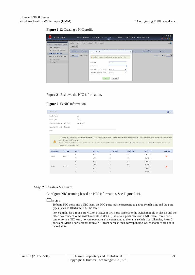
Step 1 Create NIC profiles.
NIC profiles are based on the imported NIC information of compute nodes. See Figure 2-12.
Huawei E9000 Server
easyLink Feature White Paper (HMM) 2 Configuring E9000 easyLink
Issue 02 (2017-03-31) Huawei Proprietary and Confidential
Copyright © Huawei Technologies Co., Ltd.
24
Figure 2-12 Creating a NIC profile
Figure 2-13 shows the NIC information.
Figure 2-13 NIC information
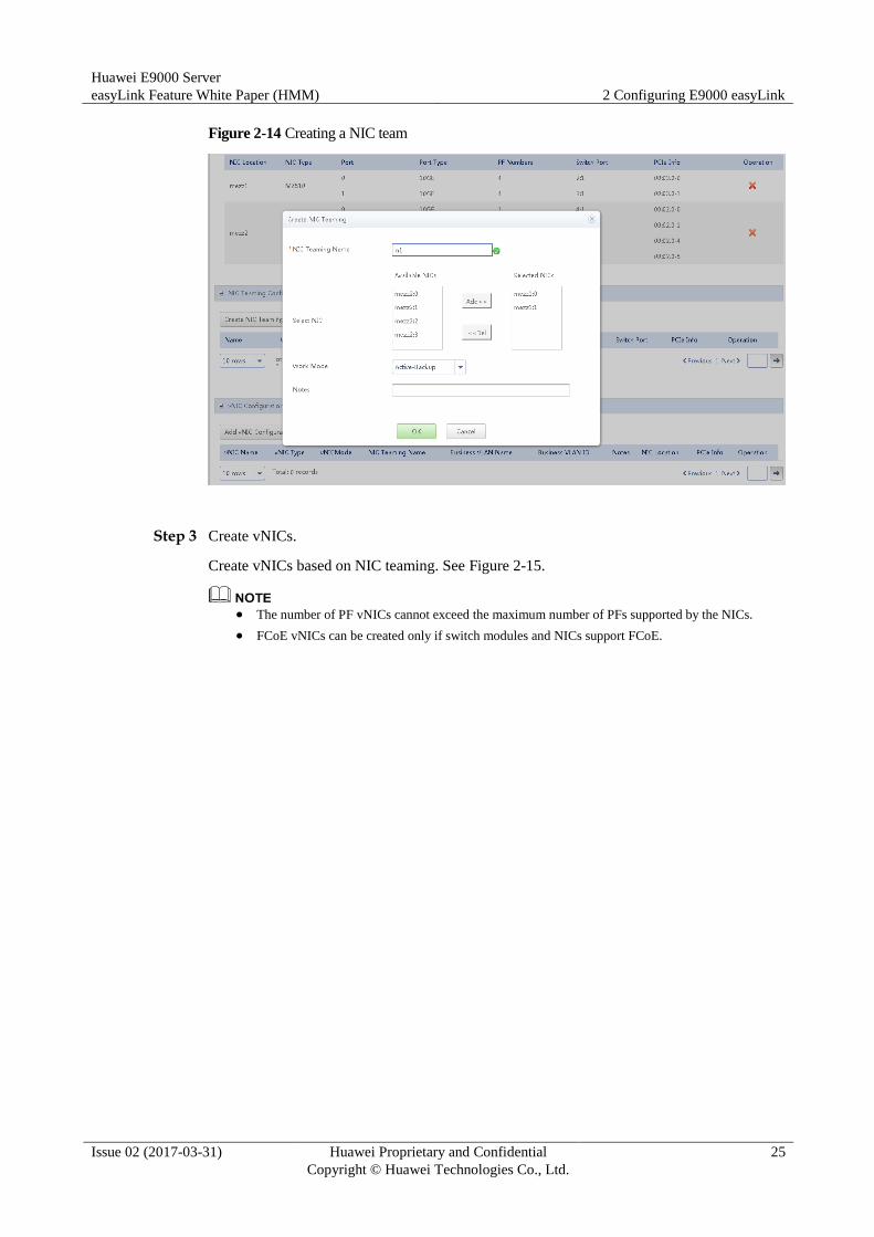
Step 2 Create a NIC team.
Configure NIC teaming based on NIC information. See Figure 2-14.
To bond NIC ports into a NIC team, the NIC ports must correspond to paired switch slots and the port
types (such as 10GE) must be the same.
For example, for a four-port NIC on Mezz 2, if two ports connect to the switch module in slot 1E and the
other two connect to the switch module in slot 4E, these four ports can form a NIC team. Three ports
cannot form a NIC team, nor can two ports that correspond to the same switch slot. Likewise, Mezz 2
ports and Mezz 1 ports cannot form a NIC team because their corresponding switch modules are not in
paired slots.
Huawei E9000 Server
easyLink Feature White Paper (HMM) 2 Configuring E9000 easyLink
Issue 02 (2017-03-31) Huawei Proprietary and Confidential
Copyright © Huawei Technologies Co., Ltd.
25
Figure 2-14 Creating a NIC team
Step 3 Create vNICs.
Create vNICs based on NIC teaming. See Figure 2-15.
The number of PF vNICs cannot exceed the maximum number of PFs supported by the NICs.
FCoE vNICs can be created only if switch modules and NICs support FCoE.

Huawei E9000 Server
easyLink Feature White Paper (HMM) 2 Configuring E9000 easyLink
Issue 02 (2017-03-31) Huawei Proprietary and Confidential
Copyright © Huawei Technologies Co., Ltd.
26
Figure 2-15 Creating a vNIC
Step 4 Bond the NIC profiles to slots.
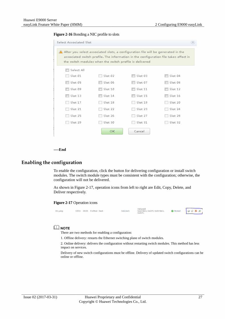
Bond the NIC profiles to required slots. See Figure 2-16.
Bond the NIC profiles to the slots in which the compute node types, NIC types, and NIC installation
status are consistent to the profiles. Otherwise, alarms are generated and the compute node network may
fail.
Huawei E9000 Server
easyLink Feature White Paper (HMM) 2 Configuring E9000 easyLink
Issue 02 (2017-03-31) Huawei Proprietary and Confidential
Copyright © Huawei Technologies Co., Ltd.
27
Figure 2-16 Bonding a NIC profile to slots
----End
Enabling the configuration
To enable the configuration, click the button for delivering configuration or install switch
modules. The switch module types must be consistent with the configuration; otherwise, the
configuration will not be delivered.
As shown in Figure 2-17, operation icons from left to right are Edit, Copy, Delete, and
Deliver respectively.
Figure 2-17 Operation icons
There are two methods for enabling a configuration:
1. Offline delivery: restarts the Ethernet switching plane of switch modules.
2. Online delivery: delivers the configuration without restarting switch modules. This method has less
impact on services.
Delivery of new switch configurations must be offline. Delivery of updated switch configurations can be
online or offline.
Huawei E9000 Server
easyLink Feature White Paper (HMM) 2 Configuring E9000 easyLink
Issue 02 (2017-03-31) Huawei Proprietary and Confidential
Copyright © Huawei Technologies Co., Ltd.
28
2.2 Service Configuration Instances
2.2.1 Stacked Networking (1)
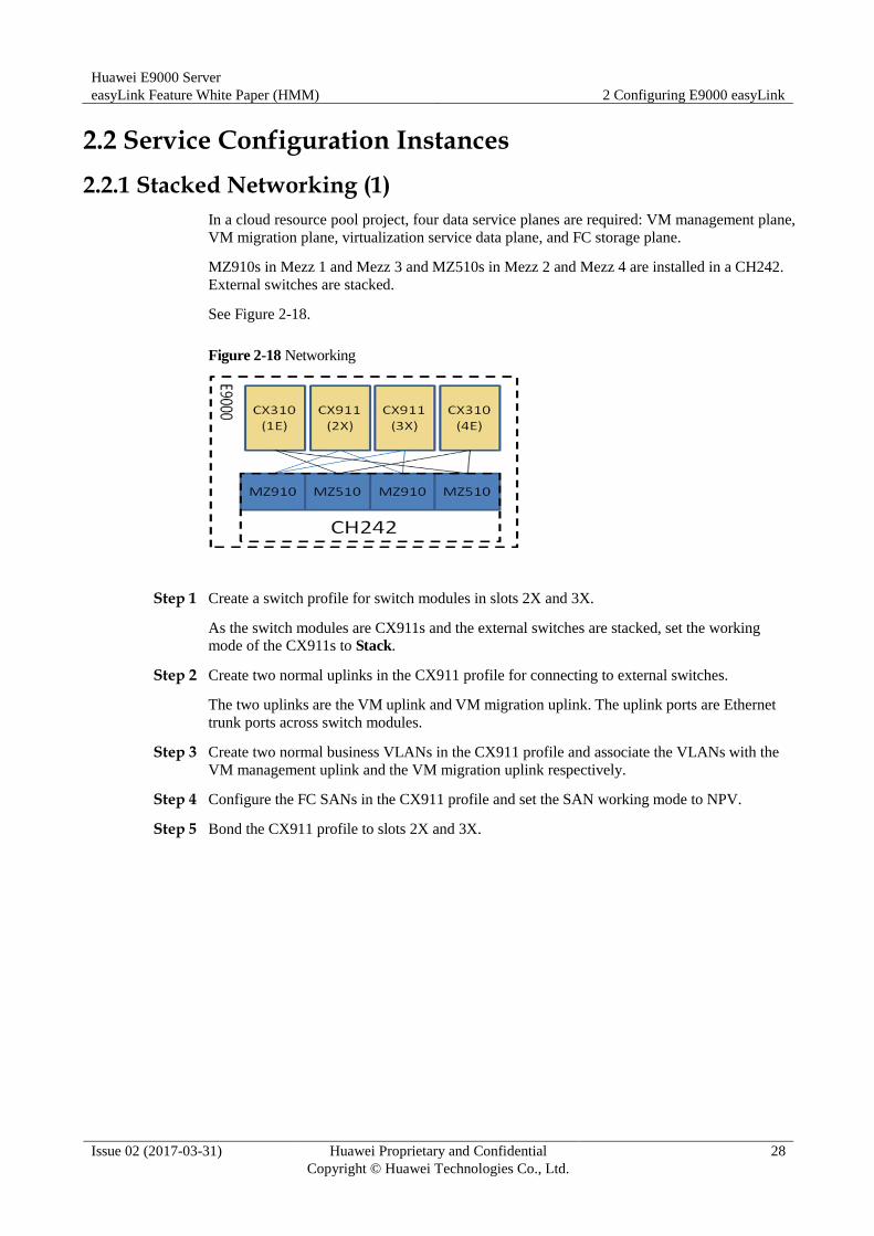
In a cloud resource pool project, four data service planes are required: VM management plane,
VM migration plane, virtualization service data plane, and FC storage plane.
MZ910s in Mezz 1 and Mezz 3 and MZ510s in Mezz 2 and Mezz 4 are installed in a CH242.
External switches are stacked.
See Figure 2-18.
Figure 2-18 Networking
Step 1 Create a switch profile for switch modules in slots 2X and 3X.
As the switch modules are CX911s and the external switches are stacked, set the working
mode of the CX911s to Stack.
Step 2 Create two normal uplinks in the CX911 profile for connecting to external switches.
The two uplinks are the VM uplink and VM migration uplink. The uplink ports are Ethernet
trunk ports across switch modules.
Step 3 Create two normal business VLANs in the CX911 profile and associate the VLANs with the
VM management uplink and the VM migration uplink respectively.
Step 4 Configure the FC SANs in the CX911 profile and set the SAN working mode to NPV.
Step 5 Bond the CX911 profile to slots 2X and 3X.
Huawei E9000 Server
easyLink Feature White Paper (HMM) 2 Configuring E9000 easyLink
Issue 02 (2017-03-31) Huawei Proprietary and Confidential
Copyright © Huawei Technologies Co., Ltd.
29
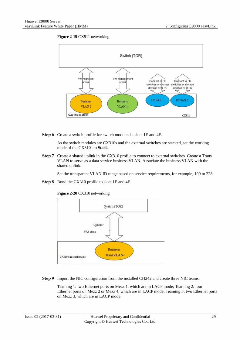
Figure 2-19 CX911 networking
Step 6 Create a switch profile for switch modules in slots 1E and 4E.
As the switch modules are CX310s and the external switches are stacked, set the working
mode of the CX310s to Stack.
Step 7 Create a shared uplink in the CX310 profile to connect to external switches. Create a Trans
VLAN to serve as a data service business VLAN. Associate the business VLAN with the
shared uplink.
Set the transparent VLAN ID range based on service requirements, for example, 100 to 228.
Step 8 Bond the CX310 profile to slots 1E and 4E.
Figure 2-20 CX310 networking
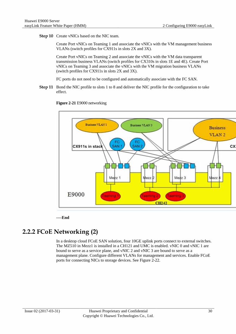
Step 9 Import the NIC configuration from the installed CH242 and create three NIC teams.
Teaming 1: two Ethernet ports on Mezz 1, which are in LACP mode; Teaming 2: four
Ethernet ports on Mezz 2 or Mezz 4, which are in LACP mode; Teaming 3: two Ethernet ports
on Mezz 3, which are in LACP mode.
Huawei E9000 Server
easyLink Feature White Paper (HMM) 2 Configuring E9000 easyLink
Issue 02 (2017-03-31) Huawei Proprietary and Confidential
Copyright © Huawei Technologies Co., Ltd.
30
Step 10 Create vNICs based on the NIC team.
Create Port vNICs on Teaming 1 and associate the vNICs with the VM management business
VLANs (switch profiles for CX911s in slots 2X and 3X).
Create Port vNICs on Teaming 2 and associate the vNICs with the VM data transparent
transmission business VLANs (switch profiles for CX310s in slots 1E and 4E). Create Port
vNICs on Teaming 3 and associate the vNICs with the VM migration business VLANs
(switch profiles for CX911s in slots 2X and 3X).
FC ports do not need to be configured and automatically associate with the FC SAN.
Step 11 Bond the NIC profile to slots 1 to 8 and deliver the NIC profile for the configuration to take
effect.
Figure 2-21 E9000 networking
----End
2.2.2 FCoE Networking (2)
In a desktop cloud FCoE SAN solution, four 10GE uplink ports connect to external switches.
The MZ510 in Mezz1 is installed in a CH121 and UMC is enabled. vNIC 0 and vNIC 1 are
bound to serve as a service plane, and vNIC 2 and vNIC 3 are bound to serve as a
management plane. Configure different VLANs for management and services. Enable FCoE
ports for connecting NICs to storage devices. See Figure 2-22.

Huawei E9000 Server
easyLink Feature White Paper (HMM) 2 Configuring E9000 easyLink
Issue 02 (2017-03-31) Huawei Proprietary and Confidential
Copyright © Huawei Technologies Co., Ltd.
31
Figure 2-22 FCoE networking
Step 1 Create a switch profile for switch modules in slots 2X and 3X. The switch modules are
CX311s that work in stack mode.
Step 2 Create two normal uplinks in the CX311 profile for connecting to external switches.
The two uplinks are the management uplink and service data uplink. The uplink ports are
Ethernet trunk ports across switch modules.
Step 3 Create two normal business VLANs in the CX311 profile.
Associate the two VLANs with the management uplink and service data uplink.
Step 4 Deliver the CX311 profile to slots 2X and 3X.
Figure 2-23 CX311 networking
Step 5 Import NIC (the MZ510 in Mezz1) configuration from the installed CH121, and create the
NIC Teaming (two ports on the MZ510 in Mezz1). Two Ethernet ports work in active/backup
mode and FCoE ports must work in active/backup mode.

Huawei E9000 Server
easyLink Feature White Paper (HMM) 2 Configuring E9000 easyLink
Issue 02 (2017-03-31) Huawei Proprietary and Confidential
Copyright © Huawei Technologies Co., Ltd.
32
Step 6 Create three vNICs in the NIC Teaming. Two are Ethernet or PF vNICs that associate with
the data service business VLAN and management VLAN respectively, and the other one is an
FC or PF vNIC that does not associate with a VLAN.
Step 7 Bond the NIC profile to slots 0 to 6 and deliver the NIC profile for the configuration to take
effect.
Figure 2-24 E9000 networking
----End
2.2.3 FCoE Networking (3)
2.2.3.1 FCF Application Scenario
A Fibre Channel Forwarder (FCF) switch supports both FCoE and FC protocol stacks for
connecting to SAN and LAN environments. In an FC SAN, an FCF is mainly used for
transmitting FC data. An FCF forwards FCoE packets and encapsulates or decapsulates FCoE
packets.
Huawei E9000 Server
easyLink Feature White Paper (HMM) 2 Configuring E9000 easyLink
Issue 02 (2017-03-31) Huawei Proprietary and Confidential
Copyright © Huawei Technologies Co., Ltd.
33
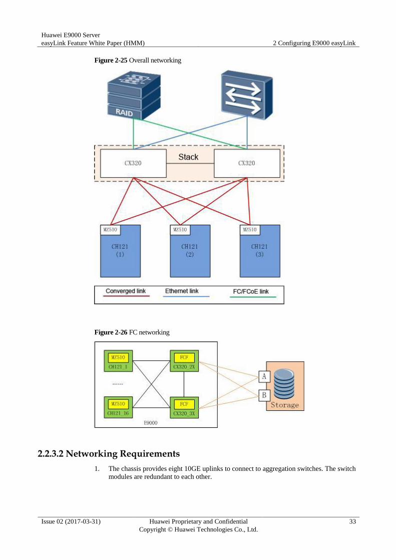
Figure 2-25 Overall networking
Figure 2-26 FC networking
2.2.3.2 Networking Requirements
1. The chassis provides eight 10GE uplinks to connect to aggregation switches. The switch
modules are redundant to each other.
Huawei E9000 Server
easyLink Feature White Paper (HMM) 2 Configuring E9000 easyLink
Issue 02 (2017-03-31) Huawei Proprietary and Confidential
Copyright © Huawei Technologies Co., Ltd.
34
2. The chassis provides four 8 Gbit/s uplinks to directly connect to dual-controller FC
storage (such as S3900), or provides four 10 Gbit/s uplinks to directly connect to
dual-controller FCoE storage.
The CX320 switch module can directly connect to storage by using FC or FCoE ports. To use FCoE
ports to connect to storage, the storage device needs to provide FCoE ports.
3. Three types of services run on different physical network adapters of each compute node.
Multiple physical network adapters share two 10GE uplinks.
In this scenario, FC ports are directly connected to storage. To directly connect FC ports to external FC
switches, see 2.2.4 FCoE Networking (4).
2.2.3.3 Physical Networking Description
Install two CX320 converged switch modules in slots 2X and 3X, which use FC or FCoE
uplinks to connect to storage and Ethernet uplinks to connect to the aggregation switch.
Configure the two CX320 switch modules as a stack by using the default stack IDs and
the 40GE midplane links as cascading channels. Enable local preferential forwarding for
the uplink Eth-Trunk ports.
Install CH121 half-width compute nodes in slots 1, 2, and 3, install MZ510 converged
network adapters in their Mezz1 positions. Each MZ510 provides one 10GE link to
connect to each CX320.
Connect ports 10GE 2/17/1 to 2/17/4 and 3/17/1 to 3/17/4 of the CX320 panels to the
uplink aggregation switch.
Connect subcard ports FC 2/21/1, FC 2/21/2, FC 3/21/1, and FC 3/21/2 of the CX320 to
the uplink FC storage, or connect panel ports 10GE 2/17/7, 10GE 2/17/8, 10GE 3/17/7,
and 10GE 3/17/8 on the CX320 to the uplink FCoE storage.
The CX320 switch module can directly connect to storage by using FC or FCoE ports. If FC ports are
used to directly connect to storage, only subcard ports can be converted to FC ports. If FCoE ports are
used to directly connect to storage, use panel ports or subcard ports. The two situations require different
configurations, which are described in the following sections.
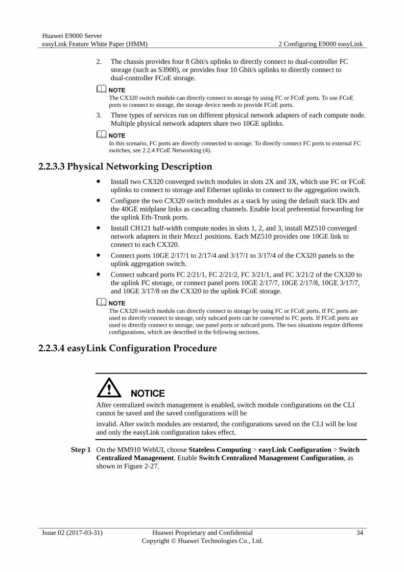
2.2.3.4 easyLink Configuration Procedure
After centralized switch management is enabled, switch module configurations on the CLI
cannot be saved and the saved configurations will be
invalid. After switch modules are restarted, the configurations saved on the CLI will be lost
and only the easyLink configuration takes effect.
Step 1 On the MM910 WebUI, choose Stateless Computing > easyLink Configuration > Switch
Centralized Management. Enable Switch Centralized Management Configuration, as
shown in Figure 2-27.
Huawei E9000 Server
easyLink Feature White Paper (HMM) 2 Configuring E9000 easyLink
Issue 02 (2017-03-31) Huawei Proprietary and Confidential
Copyright © Huawei Technologies Co., Ltd.
35
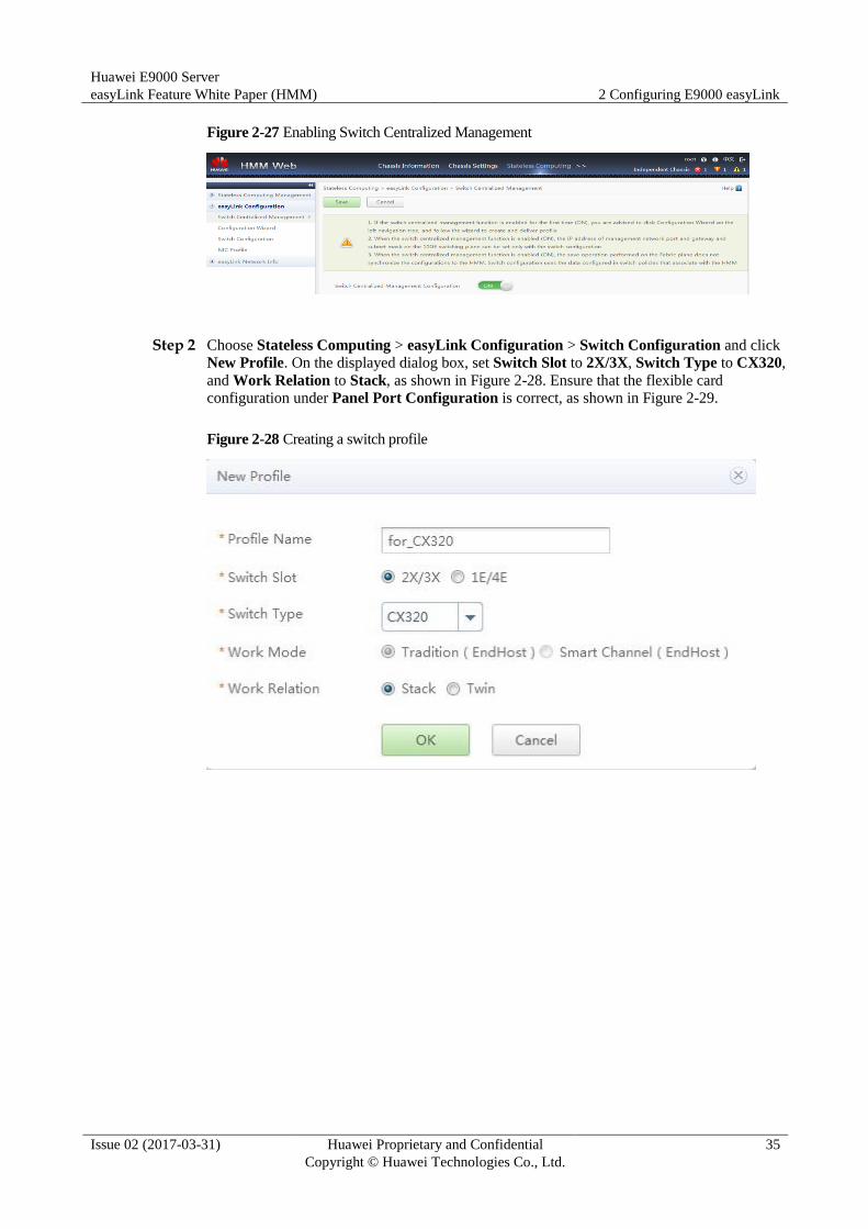
Figure 2-27 Enabling Switch Centralized Management
Step 2 Choose Stateless Computing > easyLink Configuration > Switch Configuration and click
New Profile. On the displayed dialog box, set Switch Slot to 2X/3X, Switch Type to CX320,
and Work Relation to Stack, as shown in Figure 2-28. Ensure that the flexible card
configuration under Panel Port Configuration is correct, as shown in Figure 2-29.
Figure 2-28 Creating a switch profile
Huawei E9000 Server
easyLink Feature White Paper (HMM) 2 Configuring E9000 easyLink
Issue 02 (2017-03-31) Huawei Proprietary and Confidential
Copyright © Huawei Technologies Co., Ltd.
36
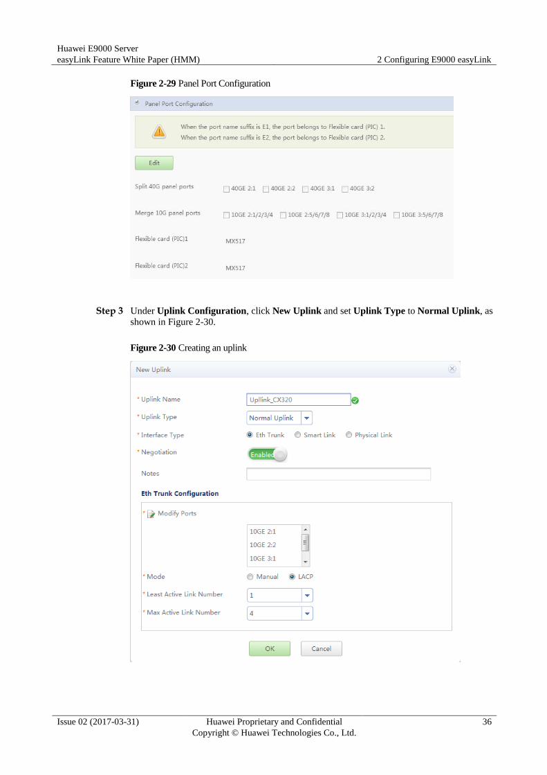
Figure 2-29 Panel Port Configuration
Step 3 Under Uplink Configuration, click New Uplink and set Uplink Type to Normal Uplink, as
shown in Figure 2-30.
Figure 2-30 Creating an uplink
Huawei E9000 Server
easyLink Feature White Paper (HMM) 2 Configuring E9000 easyLink
Issue 02 (2017-03-31) Huawei Proprietary and Confidential
Copyright © Huawei Technologies Co., Ltd.
37
Step 4 Under Business VLAN Configuration, click New Business VLAN, set VLAN Type to
Normal Vlan, and associate with the uplink created in Step 3.
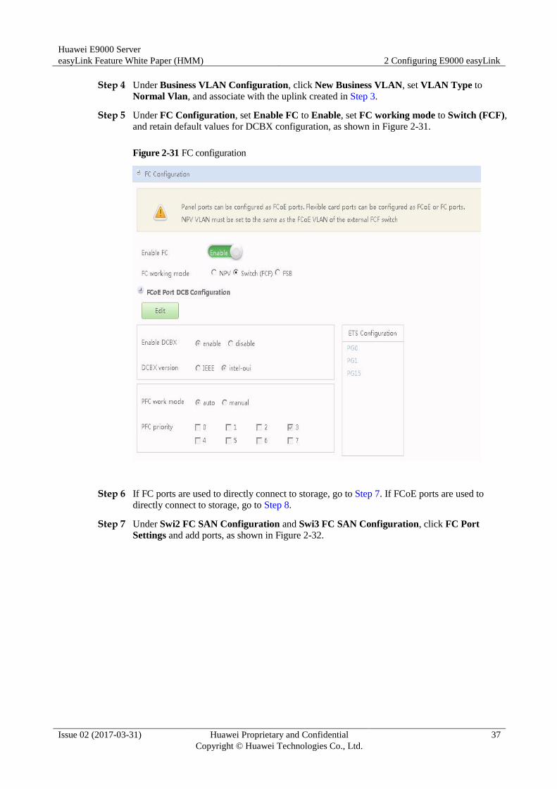
Step 5 Under FC Configuration, set Enable FC to Enable, set FC working mode to Switch (FCF),
and retain default values for DCBX configuration, as shown in Figure 2-31.
Figure 2-31 FC configuration
Step 6 If FC ports are used to directly connect to storage, go to Step 7. If FCoE ports are used to
directly connect to storage, go to Step 8.
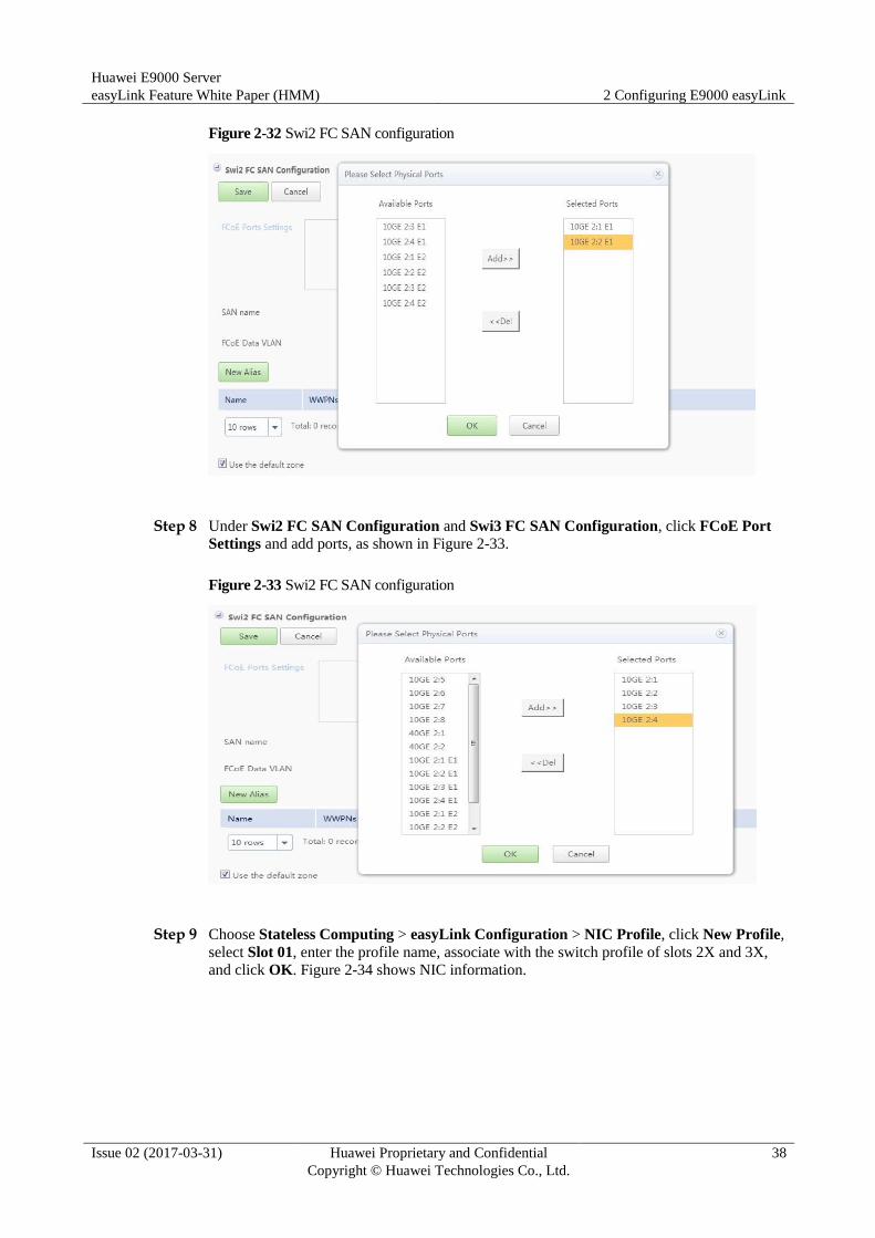
Step 7 Under Swi2 FC SAN Configuration and Swi3 FC SAN Configuration, click FC Port
Settings and add ports, as shown in Figure 2-32.
Huawei E9000 Server
easyLink Feature White Paper (HMM) 2 Configuring E9000 easyLink
Issue 02 (2017-03-31) Huawei Proprietary and Confidential
Copyright © Huawei Technologies Co., Ltd.
38
Figure 2-32 Swi2 FC SAN configuration
Step 8 Under Swi2 FC SAN Configuration and Swi3 FC SAN Configuration, click FCoE Port
Settings and add ports, as shown in Figure 2-33.
Figure 2-33 Swi2 FC SAN configuration
Step 9 Choose Stateless Computing > easyLink Configuration > NIC Profile, click New Profile,
select Slot 01, enter the profile name, associate with the switch profile of slots 2X and 3X,
and click OK. Figure 2-34 shows NIC information.

Huawei E9000 Server
easyLink Feature White Paper (HMM) 2 Configuring E9000 easyLink
Issue 02 (2017-03-31) Huawei Proprietary and Confidential
Copyright © Huawei Technologies Co., Ltd.
39
Figure 2-34 NIC information
Step 10 Click Create NIC Teaming, add NIC ports, set the PVID (optional and usually left empty),
retain the default work mode Active-Backup, and click OK, as shown in Figure 2-35.
Figure 2-35 Creating a NIC team
Step 11 Click Add vNIC Configuration, enter the vNIC name, select the NIC team created in Step
10, set vNIC Type to FCoE, set Mode to PF, and click OK, as shown in Figure 2-36. Click
Add vNIC Configuration, enter the vNIC name, select the NIC team created in Step 10, set
vNIC Type to Ethernet, set Mode to PF, select the business VLAN created in Step 4, and
click OK, as shown in Figure 2-37.

Huawei E9000 Server
easyLink Feature White Paper (HMM) 2 Configuring E9000 easyLink
Issue 02 (2017-03-31) Huawei Proprietary and Confidential
Copyright © Huawei Technologies Co., Ltd.
40
Figure 2-36 Creating an FCoE vNIC
Figure 2-37 Creating an Ethernet vNIC
Step 12 Return to the NIC profile list, click None in the Associated Slot column, and select Slot 01,
Slot 02, and Slot 03, as shown in Figure 2-38.

Huawei E9000 Server
easyLink Feature White Paper (HMM) 2 Configuring E9000 easyLink
Issue 02 (2017-03-31) Huawei Proprietary and Confidential
Copyright © Huawei Technologies Co., Ltd.
41
Figure 2-38 Associating with slots
Step 13 Choose Stateless Computing > easyLink Configuration > Switch Configuration, click
None in the Associated Slot column, select Swi2/Swi3, and click OK, as shown in Figure
2-39.
Figure 2-39 Associating with slots
Step 14 Click , select Offline Delivery, and select Swi2 and Swi3, as shown in Figure 2-40.

Huawei E9000 Server
easyLink Feature White Paper (HMM) 2 Configuring E9000 easyLink
Issue 02 (2017-03-31) Huawei Proprietary and Confidential
Copyright © Huawei Technologies Co., Ltd.
42
Figure 2-40 Manually delivering a profile
----End
2.2.3.5 NIC Configuration in the OS
In the OS, create three bonds and associate each bond with two NIC ports (ethx), which are
one PF on port 0 and one on port 1. For details, see the E9000 Server V100R001 Deployment
Guide.
2.2.4 FCoE Networking (4)
2.2.4.1 NPV Application Scenario
A SAN has high demands for edge switches directly connected to node devices. N-Port
virtualization (NPV) switches do not occupy domain IDs and enable a SAN to exceed the
limit of 239 edge switches.
Huawei E9000 Server
easyLink Feature White Paper (HMM) 2 Configuring E9000 easyLink
Issue 02 (2017-03-31) Huawei Proprietary and Confidential
Copyright © Huawei Technologies Co., Ltd.
43
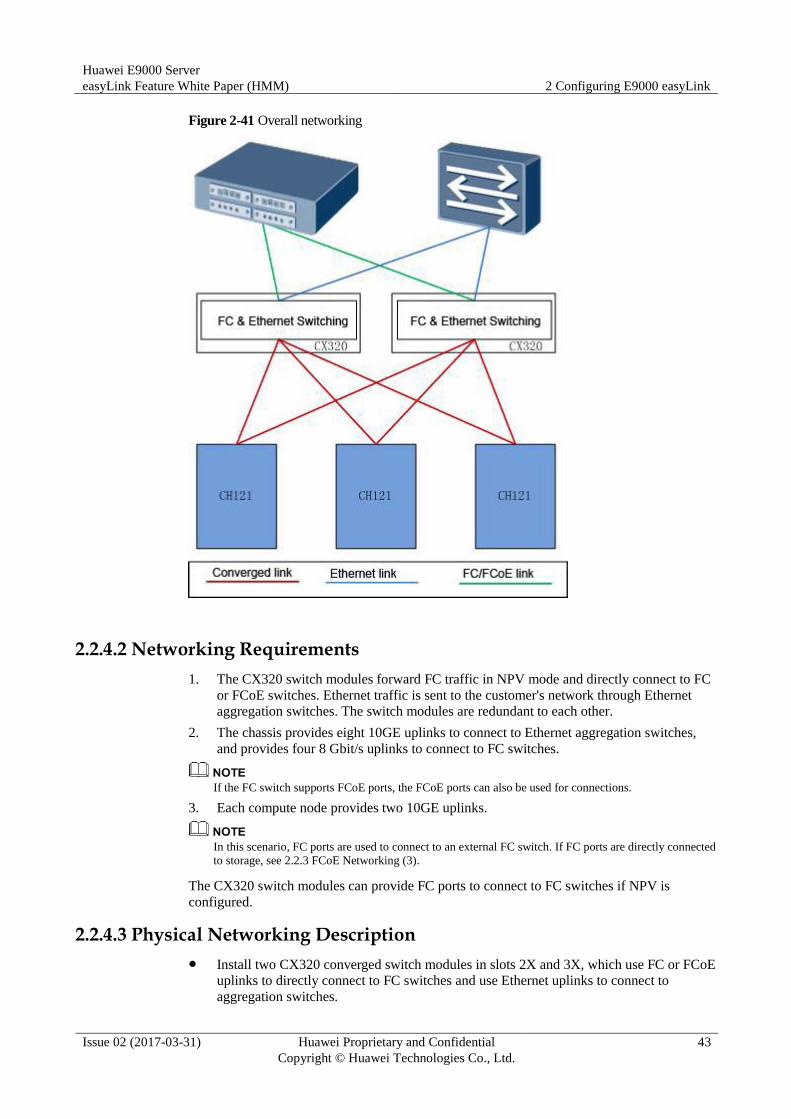
Figure 2-41 Overall networking
2.2.4.2 Networking Requirements
1. The CX320 switch modules forward FC traffic in NPV mode and directly connect to FC
or FCoE switches. Ethernet traffic is sent to the customer's network through Ethernet
aggregation switches. The switch modules are redundant to each other.
2. The chassis provides eight 10GE uplinks to connect to Ethernet aggregation switches,
and provides four 8 Gbit/s uplinks to connect to FC switches.
If the FC switch supports FCoE ports, the FCoE ports can also be used for connections.
3. Each compute node provides two 10GE uplinks.
In this scenario, FC ports are used to connect to an external FC switch. If FC ports are directly connected
to storage, see 2.2.3 FCoE Networking (3).
The CX320 switch modules can provide FC ports to connect to FC switches if NPV is
configured.
2.2.4.3 Physical Networking Description
Install two CX320 converged switch modules in slots 2X and 3X, which use FC or FCoE
uplinks to directly connect to FC switches and use Ethernet uplinks to connect to
aggregation switches.
Huawei E9000 Server
easyLink Feature White Paper (HMM) 2 Configuring E9000 easyLink
Issue 02 (2017-03-31) Huawei Proprietary and Confidential
Copyright © Huawei Technologies Co., Ltd.
44
Configure the two CX320 switch modules as a stack by using the default stack IDs and
the 40GE midplane links as cascading channels. Enable local preferential forwarding for
the uplink Eth-Trunk ports.
Install CH121 half-width compute nodes in slots 1, 2, and 3, install MZ510 converged
network adapters in their Mezz1 positions. Each MZ510 provides one 10GE link to
connect to each CX320.
Connect ports 10GE 2/17/1 to 2/17/4 and 3/17/1 to 3/17/4 of the CX320 panels to the
uplink aggregation switch.
Connect ports FC 2/21/1, FC 2/21/2, FC 3/21/1, and FC 3/21/2 of the CX320 subcards to the
uplink FC switch, or connect ports 10GE 2/17/7, 10GE 2/17/8, 10GE 3/17/7, and 10GE
3/17/8 on the CX320 panels to the uplink FCoE switch.
CX320 switch modules can use FC ports to directly connect to FC switches or use FCoE ports to
directly connect to FCoE switches. To directly connect to FC switch, only subcard ports can be used. To
directly connect to FCoE switch, use panel ports or subcard ports. The two situations require different
configurations, which are described in the following sections.
2.2.4.4 easyLink Configuration Procedure
After centralized switch management is enabled, switch module configurations on the CLI
cannot be saved and the saved configurations will be
invalid. After switch modules are restarted, the configurations saved on the CLI will be lost
and only the easyLink configuration takes effect.
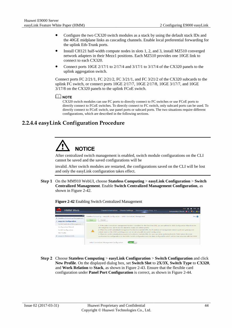
Step 1 On the MM910 WebUI, choose Stateless Computing > easyLink Configuration > Switch
Centralized Management. Enable Switch Centralized Management Configuration, as
shown in Figure 2-42.
Figure 2-42 Enabling Switch Centralized Management
Step 2 Choose Stateless Computing > easyLink Configuration > Switch Configuration and click
New Profile. On the displayed dialog box, set Switch Slot to 2X/3X, Switch Type to CX320,
and Work Relation to Stack, as shown in Figure 2-43. Ensure that the flexible card
configuration under Panel Port Configuration is correct, as shown in Figure 2-44.

Huawei E9000 Server
easyLink Feature White Paper (HMM) 2 Configuring E9000 easyLink
Issue 02 (2017-03-31) Huawei Proprietary and Confidential
Copyright © Huawei Technologies Co., Ltd.
45
Figure 2-43 Creating a switch profile
Figure 2-44 Panel Port Configuration
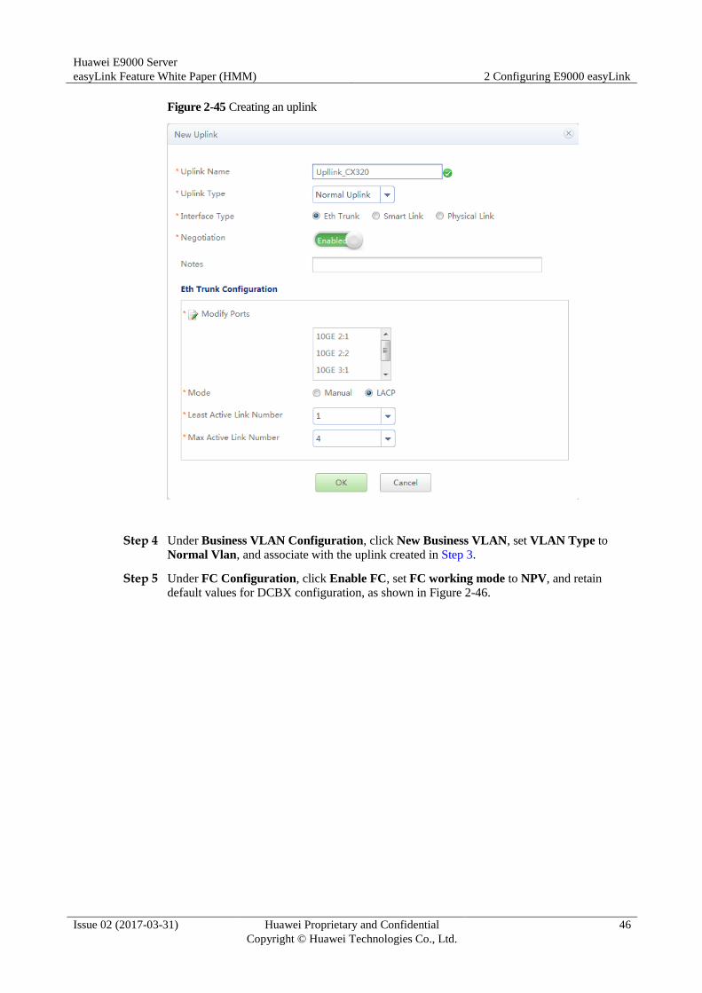
Step 3 Under Uplink Configuration, click New Uplink and set Uplink Type to Normal Uplink, as
shown in Figure 2-45.
Huawei E9000 Server
easyLink Feature White Paper (HMM) 2 Configuring E9000 easyLink
Issue 02 (2017-03-31) Huawei Proprietary and Confidential
Copyright © Huawei Technologies Co., Ltd.
46
Figure 2-45 Creating an uplink
Step 4 Under Business VLAN Configuration, click New Business VLAN, set VLAN Type to
Normal Vlan, and associate with the uplink created in Step 3.
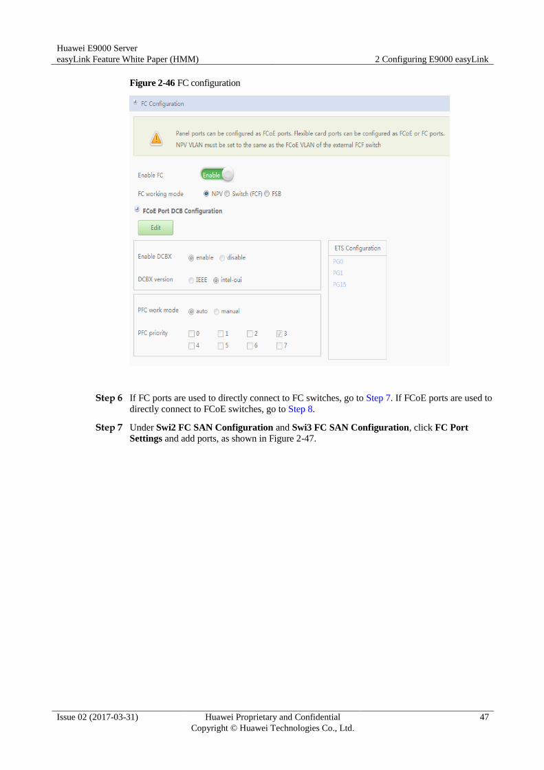
Step 5 Under FC Configuration, click Enable FC, set FC working mode to NPV, and retain
default values for DCBX configuration, as shown in Figure 2-46.
Huawei E9000 Server
easyLink Feature White Paper (HMM) 2 Configuring E9000 easyLink
Issue 02 (2017-03-31) Huawei Proprietary and Confidential
Copyright © Huawei Technologies Co., Ltd.
47
Figure 2-46 FC configuration
Step 6 If FC ports are used to directly connect to FC switches, go to Step 7. If FCoE ports are used to
directly connect to FCoE switches, go to Step 8.
Step 7 Under Swi2 FC SAN Configuration and Swi3 FC SAN Configuration, click FC Port
Settings and add ports, as shown in Figure 2-47.

Huawei E9000 Server
easyLink Feature White Paper (HMM) 2 Configuring E9000 easyLink
Issue 02 (2017-03-31) Huawei Proprietary and Confidential
Copyright © Huawei Technologies Co., Ltd.
48
Figure 2-47 Swi2 FC SAN configuration
Step 8 Under Swi2 FC SAN Configuration and Swi3 FC SAN Configuration, click FCoE Port
Settings and add ports, as shown in Figure 2-48.
NPV VLAN configuration of the CX320 must be consistent with the FCoE VLAN configuration of the
external FCF instance.
Figure 2-48 Swi2 FC SAN configuration
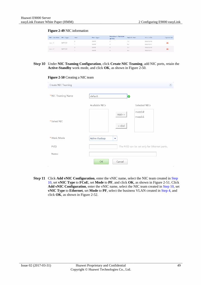
Step 9 Choose Stateless Computing > easyLink Configuration > NIC Profile, click New Profile,
select Slot 01, enter the profile name, associate with the switch profile of slots 2X and 3X,
and click OK. Figure 2-49 shows NIC information.
Huawei E9000 Server
easyLink Feature White Paper (HMM) 2 Configuring E9000 easyLink
Issue 02 (2017-03-31) Huawei Proprietary and Confidential
Copyright © Huawei Technologies Co., Ltd.
49
Figure 2-49 NIC information
Step 10 Under NIC Teaming Configuration, click Create NIC Teaming, add NIC ports, retain the
Active-Standby work mode, and click OK, as shown in Figure 2-50.
Figure 2-50 Creating a NIC team
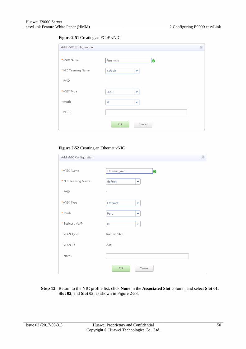
Step 11 Click Add vNIC Configuration, enter the vNIC name, select the NIC team created in Step
10, set vNIC Type to FCoE, set Mode to PF, and click OK, as shown in Figure 2-51. Click
Add vNIC Configuration, enter the vNIC name, select the NIC team created in Step 10, set
vNIC Type to Ethernet, set Mode to PF, select the business VLAN created in Step 4, and
click OK, as shown in Figure 2-52.
Huawei E9000 Server
easyLink Feature White Paper (HMM) 2 Configuring E9000 easyLink
Issue 02 (2017-03-31) Huawei Proprietary and Confidential
Copyright © Huawei Technologies Co., Ltd.
50
Figure 2-51 Creating an FCoE vNIC
Figure 2-52 Creating an Ethernet vNIC
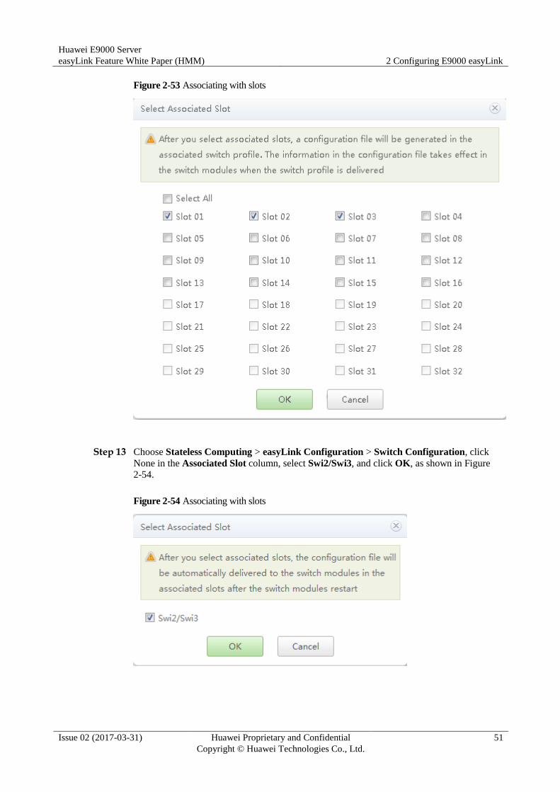
Step 12 Return to the NIC profile list, click None in the Associated Slot column, and select Slot 01,
Slot 02, and Slot 03, as shown in Figure 2-53.
Huawei E9000 Server
easyLink Feature White Paper (HMM) 2 Configuring E9000 easyLink
Issue 02 (2017-03-31) Huawei Proprietary and Confidential
Copyright © Huawei Technologies Co., Ltd.
51
Figure 2-53 Associating with slots
Step 13 Choose Stateless Computing > easyLink Configuration > Switch Configuration, click
None in the Associated Slot column, select Swi2/Swi3, and click OK, as shown in Figure
2-54.
Figure 2-54 Associating with slots

Huawei E9000 Server
easyLink Feature White Paper (HMM) 2 Configuring E9000 easyLink
Issue 02 (2017-03-31) Huawei Proprietary and Confidential
Copyright © Huawei Technologies Co., Ltd.
52
Step 14 Click , select Offline Delivery, and select Swi2 and Swi3, as shown in Figure 2-55.
Figure 2-55 Manually delivering a profile
----End
2.2.4.5 NIC Configuration in the OS
In the OS, create three bonds and associate each bond with two NIC ports (ethx), which are
one PF on port 0 and one on port 1. For details, see the E9000 Server V100R001 Deployment
Guide.

Huawei E9000 Server
easyLink Feature White Paper (HMM) A Acronyms and Abbreviations
Issue 02 (2017-03-31) Huawei Proprietary and Confidential
Copyright © Huawei Technologies Co., Ltd.
53
A Acronyms and Abbreviations
B
BIOS Basic Input Output System
BMC Baseboard Management Controller
F
FC Fiber Channel
FCoE Fiber Channel over Ethernet
M
MAC Medium Access Control
L
LACP Link Aggregation Control Protocol
P
PF Physical Function
T
TOR Top of Rack
V
VF Virtual Function
W
Huawei E9000 Server
easyLink Feature White Paper (HMM) A Acronyms and Abbreviations
Issue 02 (2017-03-31) Huawei Proprietary and Confidential
Copyright © Huawei Technologies Co., Ltd.
54
WebUI Web User Interface