eaton series gt circuit breakerspub/@electrical/... · a rg is right pole only. a1 contact eaton....
TRANSCRIPT
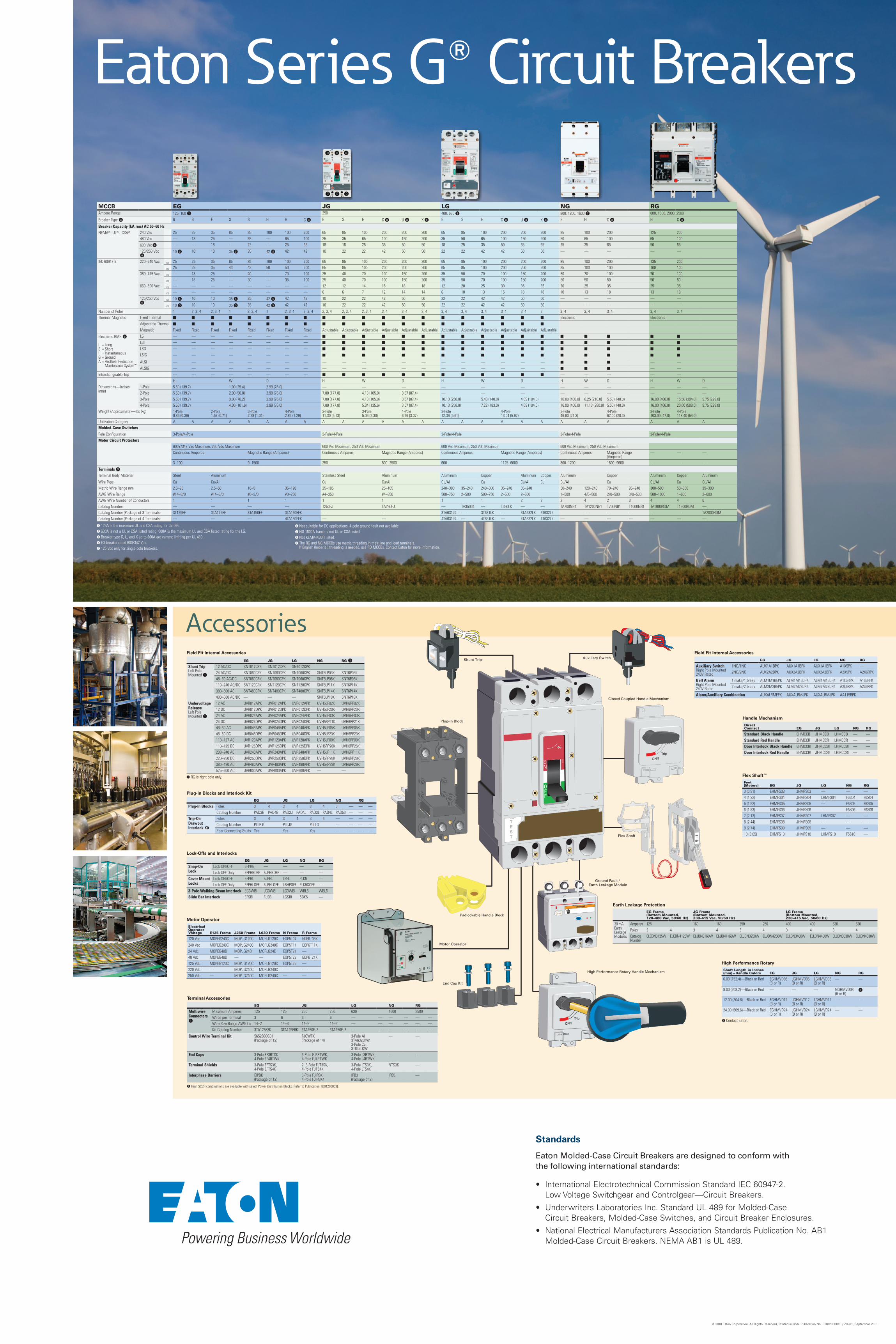
Accessories
A RG is right pole only.
A Contact Eaton.
Standards
Eaton Molded-Case Circuit Breakers are designed to conform with the following international standards:
• InternationalElectrotechnicalCommissionStandardIEC60947-2.LowVoltageSwitchgearandControlgear—CircuitBreakers.
• UnderwritersLaboratoriesInc.StandardUL489forMolded-CaseCircuitBreakers,Molded-CaseSwitches,andCircuitBreakerEnclosures.
• NationalElectricalManufacturersAssociationStandardsPublicationNo.AB1Molded-CaseCircuitBreakers.NEMAAB1isUL489.
©2010EatonCorporation,AllRightsReserved,PrintedinUSA,PublicationNo.PT01200001E/Z9981,September2010
Eaton Series GT Circuit Breakers
Motor Operator
Electrical Operator Voltage E125 Frame J250 Frame L630 Frame N Frame R Frame
120 Vac MOPEG240C MOPJG120C MOPLG120C EOP5T07 EOP6T08K
240 Vac MOPEG240C MOPJG240C MOPLG240C EOP5T11 EOP6T11K24 Vdc MOPEG48D MOPJG24D MOPLG24D EOP5T21 —48 Vdc MOPEG48D — — EOP5T22 EOP6T21K125 Vdc MOPEG120C MOPJG120C MOPLG120C EOP5T26 —220 Vdc — MOPJG240C MOPLG240C — —250 Vdc — MOPJG240C MOPLG240C — —
Handle Mechanism
Direct Connect EG JG LG NG RG
Standard Black Handle EHMCCB JHMCCB LHMCCB — —Standard Red Handle EHMCCR JHMCCR LHMCCR — —Door Interlock Black Handle EHMCCBI JHMCCBI LHMCCBI — —Door Interlock Red Handle EHMCCRI JHMCCRI LHMCCRI — —
Plug-In Blocks and Interlock Kit
EG JG LG NG RG
Plug-In Blocks Poles 3 4 3 4 3 4 3 — — —Catalog Number PAD3E PAD4E PAD3J PAD4J PAD3L PAD4L PAD53 — — —
Trip-On Drawout Interlock Kit
Poles 3 4 3 4 3 4 — — — —Catalog Number PIILE G PIILJG PIILLG — — — —Rear Connecting Studs Yes Yes Yes — — — —
Flex ShaftE
Feet (Meters) EG JG LG NG RG
3 (0.91) EHMFS03 JHMFS03 — — —4 (1.22) EHMFS04 JHMFS04 LHMFS04 F5S04 F6S045 (1.52) EHMFS05 JHMFS05 — F5S05 F6S056 (1.83) EHMFS06 JHMFS06 — F5S06 F6S067 (2.13) EHMFS07 JHMFS07 LHMFS07 — —8 (2.44) EHMFS08 JHMFS08 — — —9 (2.74) EHMFS09 JHMFS09 — — —10 (3.05) EHMFS10 JHMFS10 LHMFS10 F5S10 —
Lock-Offs and Interlocks
EG JG LG NG RG
Snap-On Lock
Lock ON/OFF EFPHB — — — —Lock OFF Only EFPHBOFF FJPHBOFF — — —
Cover Mount Locks
Lock ON/OFF EFPHL FJPHL LPHL PLK5 —Lock OFF Only EFPHLOFF FJPHLOFF LBHPOFF PLK5SOFF —
3-Pole Walking Beam Interlock EG3WBI JG3WBI LG3WBI WBL5 WBL6Slide Bar Interlock EFSBI FJSBI LGSBI SBK5 —
MCCB EG JG LG NG RGAmpere Range 125, 160 1 250 400, 630 2 800, 1200, 1600 7 800, 1600, 2000, 2500
Breaker Type 3 B B E S S H H C 8 E S H C 8 U 8 X 8 E S H C 8 U 8 X 8 S H C 8 H C 8
Breaker Capacity (kA rms) AC 50–60 HzNEMAT, ULT, CSAT 240 Vac 25 25 35 85 85 100 100 200 65 85 100 200 200 200 65 85 100 200 200 200 85 100 200 125 200
480 Vac — 18 25 — 35 — 65 100 25 35 65 100 150 200 35 50 65 100 150 200 50 65 100 65 100
600 Vac 4 — — 18 — 22 — 25 35 18 18 25 35 50 50 18 25 35 50 65 65 25 35 65 50 65
125/250 Vdc
610 5 10 10 35 5 35 42 5 42 42 10 22 22 42 50 50 22 22 42 42 50 50 — — — — —
IEC 60947-2 220–240 Vac ICU 25 25 35 85 85 100 100 200 65 85 100 200 200 200 65 85 100 200 200 200 85 100 200 135 200ICS 25 25 35 43 43 50 50 200 65 85 100 200 200 200 65 85 100 200 200 200 85 100 100 100 100
380–415 Vac ICU — 18 25 — 40 — 70 100 25 40 70 100 150 200 35 50 70 100 150 200 50 70 100 70 100ICS — 18 25 — 30 — 35 100 25 40 70 100 150 200 35 50 70 100 150 200 50 50 50 50 50
660–690 Vac ICU — — — — — — — — 12 12 14 16 18 18 12 20 25 30 35 35 20 25 35 25 35ICS — — — — — — — — 6 6 7 12 14 14 6 10 13 15 18 18 10 13 18 13 18
125/250 Vdc
6ICU 10 5 10 10 35 5 35 42 5 42 42 10 22 22 42 50 50 22 22 42 42 50 50 — — — — —
ICS 10 5 10 10 35 5 35 42 5 42 42 10 22 22 42 50 50 22 22 42 42 50 50 — — — — —
Number of Poles 1 2, 3, 4 2, 3, 4 1 2, 3, 4 1 2, 3, 4 2, 3, 4 2, 3, 4 2, 3, 4 2, 3, 4 3, 4 3, 4 3, 4 3, 4 3, 4 3, 4 3, 4 3, 4 3 3, 4 3, 4 3, 4 3, 4 3, 4Thermal-Magnetic Fixed Thermal ■ ■ ■ ■ ■ ■ ■ ■ ■ ■ ■ ■ ■ ■ ■ ■ ■ ■ ■ ■ Electronic Electronic
Adjustable Thermal ■ ■ ■ ■ ■ ■ ■ ■ ■ ■ ■ ■ ■ ■ ■ ■ ■ ■ ■ ■
Magnetic Fixed Fixed Fixed Fixed Fixed Fixed Fixed Fixed Adjustable Adjustable Adjustable Adjustable Adjustable Adjustable Adjustable Adjustable Adjustable Adjustable Adjustable Adjustable
Electronic RMS 6
L = LongS = ShortI = InstantaneousG = GroundA = Arcflash Reduction Maintenance SystemE
LS — — — — — — — — ■ ■ ■ ■ ■ ■ ■ ■ ■ ■ ■ ■ ■ ■ ■ ■ ■
LSI — — — — — — — — ■ ■ ■ ■ ■ ■ ■ ■ ■ ■ ■ ■ ■ ■ ■ ■ ■
LSG — — — — — — — — ■ ■ ■ ■ ■ ■ ■ ■ ■ ■ ■ ■ ■ ■ ■ ■ ■
LSIG — — — — — — — — ■ ■ ■ ■ ■ ■ ■ ■ ■ ■ ■ ■ ■ ■ ■ ■ ■
ALSI — — — — — — — — — — — — — — — — — — — — ■ ■ ■ — —
ALSIG — — — — — — — — — — — — — — — — — — — — ■ ■ ■ — —
Interchangeable Trip — — — — — — — — ■ ■ ■ ■ ■ ■ ■ ■ ■ ■ ■ ■ — — — — —
H W D H W D H W D H W D H W DDimensions— Inches (mm)
1-Pole 5.50 (139.7) 1.00 (25.4) 2.99 (76.0) — — — — — — — — — — — —2-Pole 5.50 (139.7) 2.00 (50.8) 2.99 (76.0) 7.00 (177.8) 4.13 (105.0) 3.57 (87.4) — — — — — — — — —3-Pole 5.50 (139.7) 3.00 (76.2) 2.99 (76.0) 7.00 (177.8) 4.13 (105.0) 3.57 (87.4) 10.13 (258.0) 5.48 (140.0) 4.09 (104.0) 16.00 (406.0) 8.25 (210.0) 5.50 (140.0) 16.00 (406.0) 15.50 (394.0) 9.75 (229.0)4-Pole 5.50 (139.7) 4.00 (101.6) 2.99 (76.0) 7.00 (177.8) 5.34 (135.6) 3.57 (87.4) 10.13 (258.0) 7.22 (183.0) 4.09 (104.0) 16.00 (406.0) 11.13 (280.0) 5.50 (140.0) 16.00 (406.0) 20.00 (508.0) 9.75 (229.0)
Weight (Approximate)—lbs (kg) 1-Pole0.85 (0.39)
2-Pole1.57 (0.71)
3-Pole2.28 (1.04)
4-Pole2.85 (1.29)
2-Pole11.30 (5.13)
3-Pole5.06 (2.30)
4-Pole6.76 (3.07)
3-Pole12.36 (5.61)
4-Pole13.04 (5.92)
3-Pole46.80 (21.3)
4-Pole62.00 (28.3)
3-Pole103.00 (47.0)
4-Pole118.40 (54.0)
Utilization Category A A A A A A A A A A A A A A A A A A A A A A A A A AMolded-Case Switches
Pole Configuration 3-Pole/4-Pole 3-Pole/4-Pole 3-Pole/4-Pole 3-Pole/4-Pole 3-Pole/4-PoleMotor Circuit Protectors
600Y/347 Vac Maximum, 250 Vdc Maximum 600 Vac Maximum, 250 Vdc Maximum 600 Vac Maximum, 250 Vdc Maximum 600 Vac Maximum, 250 Vdc MaximumContinuous Amperes Magnetic Range (Amperes) Continuous Amperes Magnetic Range (Amperes) Continuous Amperes Magnetic Range (Amperes) Continuous Amperes Magnetic Range
(Amperes)— — —
3–100 9–1500 250 500–2500 600 1125–6000 800–1200 1600–9600 — — —
Terminals 9Terminal Body Material Steel Aluminum Stainless Steel Aluminum Aluminum Copper Aluminum Copper Aluminum Copper Aluminum Copper Aluminum
Wire Type Cu Cu/Al Cu Cu/Al Cu/Al Cu Cu/Al Cu Cu/Al Cu Cu/Al Cu Cu/AlMetric Wire Range mm 2.5–95 2.5–50 16–5 35–120 25–185 25–185 240–380 35–240 240–380 35–240 35–240 50–240 120–240 70–240 95–240 300–500 50–300 35–300AWG Wire Range #14–3/0 #14–3/0 #6–3/0 #3–250 #4–350 #4–350 500–750 2–500 500–750 2–500 2–500 1–500 4/0–500 2/0–500 3/0–500 500–1000 1–600 2–600AWG Wire Number of Conductors 1 1 1 1 1 1 1 1 2 2 2 4 2 3 4 4 6Catalog Number — — — — T250FJ TA250FJ — TA350LK — T350LK — — TA700NB1 TA1200NB1 T700NB1 T1000NB1 TA1600RDM T1600RDM —Catalog Number (Package of 3 Terminals) 3T125EF 3TA125EF 3TA150EF 3TA160EFK — — 3TA631LK — 3T631LK — 3TA632LK 3T632LK — — — — — — TA2000RDMCatalog Number (Package of 4 Terminals) — — — 4TA160EFK — — 4TA631LK — 4T631LK — 4TA632LK 4T632LK — — — — — — —
A 125A is the maximum UL and CSA rating for the EG. B 630A is not a UL or CSA listed rating. 600A is the maximum UL and CSA listed rating for the LG. C Breaker type C, U, and X up to 600A are current limiting per UL 489. D EG breaker rated 600/347 Vac. E 125 Vdc only for single-pole breakers.
F Not suitable for DC applications. 4-pole ground fault not available. G NG 1600A frame is not UL or CSA listed. H Not KEMA-KEUR listed. I The RG and NG MCCBs use metric threading in their line and load terminals.
If English (Imperial) threading is needed, use RD MCCBs. Contact Eaton for more information.
Field Fit Internal Accessories
EG JG LG NG RG 1
Shunt Trip Left Pole Mounted 1
12 AC/DC SNT012CPK SNT012CPK SNT012CPK — —24 AC/DC SNT060CPK SNT060CPK SNT060CPK SNT5LP03K SNT6P03K48–60 AC/DC SNT060CPK SNT060CPK SNT060CPK SNT5LP05K SNT6P05K110–240 AC/DC SNT120CPK SNT120CPK SNT120CPK SNT5LP11K SNT6P11K380–600 AC SNT480CPK SNT480CPK SNT480CPK SNT5LP14K SNT6P14K480–600 AC/DC — — — SNT5LP18K SNT6P18K
Undervoltage ReleaseLeft Pole Mounted 1
12 AC UVR012APK UVR012APK UVR012APK UVH5LP02K UVH6RP02K12 DC UVR012DPK UVR012DPK UVR012DPK UVH5LP20K UVH6RP20K24 AC UVR024APK UVR024APK UVR024APK UVH5LP03K UVH6RP03K24 DC UVR024DPK UVR024DPK UVR024DPK UVH5RP21K UVH6RP21K48–60 AC UVR048APK UVR048APK UVR048APK UVH5LP05K UVH6RP05K48–60 DC UVR048DPK UVR048DPK UVR048DPK UVH5LP23K UVH6RP23K110–127 AC UVR120APK UVR120APK UVR120APK UVH5LP08K UVH6RP08K110–125 DC UVR125DPK UVR125DPK UVR125DPK UVH5RP26K UVH6RP26K208–240 AC UVR240APK UVR240APK UVR240APK UVH5LP11K UVH6RP11K220–250 DC UVR250DPK UVR250DPK UVR250DPK UVH5RP28K UVH6RP28K380–480 AC UVR480APK UVR480APK UVR480APK UVH5RP29K UVH6RP29K525–600 AC UVR600APK UVR600APK UVR600APK — —
Flex Shaft
Ground Fault / Earth Leakage Module
High Performance Rotary Handle Mechanism
Padlockable Handle Block
Shunt Trip
End Cap Kit
Plug-In Block
Auxiliary Switch
Closed Coupled Handle Mechanism
Motor Operator
Field Fit Internal Accessories
EG JG LG NG RG
Auxiliary SwitchRight Pole Mounted 240V Rated
1NO/1NC AUX1A1BPK AUX1A1BPK AUX1A1BPK A1X5PK —2NO/2NC AUX2A2BPK AUX2A2BPK AUX2A2BPK A2X5PK A2X6RPK
Bell AlarmRight Pole Mounted 240V Rated
1 make/1 break ALM1M1BEPK ALM1M1BJPK ALM1M1BJPK A1L5RPK A1L6RPK2 make/2 break ALM2M2BEPK ALM2M2BJPK ALM2M2BJPK A2L5RPK A2L6RPK
Alarm/Auxiliary Combination AUXALRMEPK AUXALRMJPK AUXALRMJPK AA115RPK —
High Performance Rotary
Shaft Length in Inches (mm)—Handle Colors EG JG LG NG RG
6.00 (152.4)—Black or Red EGHMVD06 (B or R)
JGHMVD06 (B or R)
LGHMVD06 (B or R)
— —
8.00 (203.2)—Black or Red — — — NGHMVD08 (B or R)
1
12.00 (304.8)—Black or Red EGHMVD12 (B or R)
JGHMVD12 (B or R)
LGHMVD12 (B or R)
— —
24.00 (609.6)—Black or Red EGHMVD24 (B or R)
JGHMVD24 (B or R)
LGHMVD24 (B or R)
— —
Earth Leakage Protection
EG Frame (Bottom Mounted, 120–480 Vac, 50/60 Hz)
JG Frame (Bottom Mounted, 230–415 Vac, 50/60 Hz)
LG Frame (Bottom Mounted, 230–415 Vac, 50/60 Hz)
30 mA Earth Leakage Modules
Amperes 125 160 160 250 250 400 400 630 630Poles 3 4 3 4 3 4 3 4 3 4Catalog Number
ELEBN3125W ELEBN4125W ELJBN3160W ELJBN4160W ELJBN3250W ELJBN4250W ELLBN3400W ELLBN4400W ELLBN3630W ELLBN4630W
Terminal Accessories
EG JG LG NG RG
Multiwire Connectors1
Maximum Amperes 125 125 250 250 630 1600 2500Wires per Terminal 3 6 3 6 — — — — — —Wire Size Range AWG Cu 14–2 14–6 14–2 14–6 — — — — — —Kit Catalog Number 3TA125E3K 3TA125E6K 3TA250FJ3 3TA250FJ6 — — — — — —
Control Wire Terminal Kit 5652B38G01 (Package of 12)
FJCWTK (Package of 14)
3-Pole Al 3TA632LKW, 3-Pole Cu 3T632LKW
— —
End Caps 3-Pole EF3RTDK 4-Pole EF4RTWK
3-Pole FJ3RTWK, 4-Pole FJ4RTWK
3-Pole L3RTWK, 4-Pole L4RTWK
— —
Terminal Shields 3-Pole EFTS3K, 4-Pole EFTS4K
2, 3-Pole FJT3SK, 4-Pole FJTS4K
3-Pole LTS3K, 4-Pole LTS4K
NTS3K —
Interphase Barriers EIPBK (Package of 12)
3-Pole FJIPBK, 4-Pole FJIPBK4
IPB3 (Package of 2)
IPB5 —
A High SCCR combinations are available with select Power Distribution Blocks. Refer to Publication TD01200003E.