ec800-al - dfi
TRANSCRIPT

1
Chapter 1 Introduction
EC800-ALFanless Embedded System
User’s Manual
A46810817

2
Chapter 1 Introduction
CopyrightThis publication contains information that is protected by copyright. No part of it may be re-produced in any form or by any means or used to make any transformation/adaptation without the prior written permission from the copyright holders.
This publication is provided for informational purposes only. The manufacturer makes no representations or warranties with respect to the contents or use of this manual and specifi-cally disclaims any express or implied warranties of merchantability or fitness for any particular purpose. The user will assume the entire risk of the use or the results of the use of this docu-ment. Further, the manufacturer reserves the right to revise this publication and make changes to its contents at any time, without obligation to notify any person or entity of such revisions or changes.
Changes after the publication’s first release will be based on the product’s revision. The website will always provide the most updated information.
© 2018. All Rights Reserved.
TrademarksProduct names or trademarks appearing in this manual are for identification purpose only and are the properties of the respective owners.
FCC and DOC Statement on Class BThis equipment has been tested and found to comply with the limits for a Class B digital device, pursuant to Part 15 of the FCC rules. These limits are designed to provide reason-able protection against harmful interference when the equipment is operated in a residential installation. This equipment generates, uses and can radiate radio frequency energy and, if not installed and used in accordance with the instruction manual, may cause harmful interference to radio communications. However, there is no guarantee that interference will not occur in a particular installation. If this equipment does cause harmful interference to radio or television reception, which can be determined by turning the equipment off and on, the user is encour-aged to try to correct the interference by one or more of the following measures:
• Reorient or relocate the receiving antenna.• Increase the separation between the equipment and the receiver.• Connect the equipment into an outlet on a circuit different from that to which the receiver
is connected.• Consult the dealer or an experienced radio TV technician for help.
Notice:1. The changes or modifications not expressly approved by the party responsible for compli-
ance could void the user’s authority to operate the equipment.2. Shielded interface cables must be used in order to comply with the emission limits.

3
Chapter 1 Introduction
Table of Contents
About this Manual .................................... 4
Warranty ................................................. 4
Static Electricity Precautions ..................... 4
Safety Measures....................................... 4
Safety Precautions ................................... 5
About the Package ................................... 5
Before Using the System .......................... 5
Chapter 1 - Introduction ........................... 6Overview .................................................................................6
Key Features ...........................................................................6
Specifications ...........................................................................7
Getting to Know the EC800-AL .................................................8
Mechanical Dimensions ............................................................9
Chapter 2 - Getting Started ...................... 10
Chapter 3 - Installing Devices ................... 11Removing the Chassis Cover ...................................................11
Chapter 4 - Jumper Settings ..................... 14Clear CMOS Data (bottom side) ..............................................14
Chapter 5 - Ports and Connectors ............. 17Front Panel I/O Ports .............................................................17
Rear Panel I/O Ports ..............................................................17
USB Ports................................................................................ 18Audio Ports .............................................................................. 18COM Ports/ 8-bit DIO ............................................................... 19RJ45 LAN Ports ........................................................................ 20DC-in ...................................................................................... 20Display Outputs ....................................................................... 21
I/O Connectors ......................................................................22Chassis Intrusion Connector (bottom side) .................................. 22SMBus Connector (top side) ...................................................... 22LEDs (top side) ........................................................................ 23Battery (bottom side) ............................................................... 23Power Switch (top side) ............................................................ 24USB 2.0 (top side) ................................................................... 24
Chapter 6 - Mounting Options .................. 25Wall Mount ............................................................................25
VESA Mount ..........................................................................26
DIN Rail Mount ......................................................................27
Chapter 7 - BIOS Setup ........................... 28
Chapter 8 - Supported Software ............... 40

4
Chapter 1 Introduction
About this ManualAn electronic file of this manual can be obtained from the DFI website at www.dfi.com. To download the user’s manual from our website, please go to Support > Download Center. On the Download Center page, select your product or type the model name and click "Search" to find all technical documents including the user's manual for a specific product.
Warranty1. Warranty does not cover damages or failures that arised from misuse of the product,
inability to use the product, unauthorized replacement or alteration of components and product specifications.
2. The warranty is void if the product has been subjected to physical abuse, improper instal-lation, modification, accidents or unauthorized repair of the product.
3. Unless otherwise instructed in this user’s manual, the user may not, under any circum-stances, attempt to perform service, adjustments or repairs on the product, whether in or out of warranty. It must be returned to the purchase point, factory or authorized service agency for all such work.
4. We will not be liable for any indirect, special, incidental or consequential damages to the product that has been modified or altered.
Static Electricity PrecautionsIt is quite easy to inadvertently damage your PC, system board, components or devices even before installing them in your system unit. Static electrical discharge can damage computer components without causing any signs of physical damage. You must take extra care in han-dling them to ensure against electrostatic build-up.
1. To prevent electrostatic build-up, leave the system board in its anti-static bag until you are ready to install it.
2. Wear an antistatic wrist strap.
3. Do all preparation work on a static-free surface.
4. Hold the device only by its edges. Be careful not to touch any of the components, contacts or connections.
5. Avoid touching the pins or contacts on all modules and connectors. Hold modules or connectors by their ends.
Safety MeasuresTo avoid damage to the system:• Use the correct AC input voltage range.
To reduce the risk of electric shock: • Unplug the power cord before removing the system chassis cover for installation or servic-ing. After installation or servicing, cover the system chassis before plugging the power cord.
Battery:• Danger of explosion if battery incorrectly replaced.• Replace only with the same or equivalent type recommend by the manufacturer.• Dispose of used batteries according to local ordinance.
Important:Electrostatic discharge (ESD) can damage your processor, disk drive and other com-ponents. Perform the upgrade instruction procedures described at an ESD worksta-tion only. If such a station is not available, you can provide some ESD protection by wearing an antistatic wrist strap and attaching it to a metal part of the system chas-sis. If a wrist strap is unavailable, establish and maintain contact with the system chassis throughout any procedures requiring ESD protection.

5
Chapter 1 Introduction
About the PackageThe package contains the following items. If any of these items are missing or damaged, please contact your dealer or sales representative for assistance.
• One EC800-AL system unit• One CD disk includes
- Manual- Drivers
• One Quick Installation Guide
Optional Items• Wall Mount kit• VESA Mount kit• DIN-rail Mount kit• Power Cord• Power Adapter: 60W, 12V/5A; 60W, 12V/5A (-30 to 70°C); 60W 19V/3.15A
The board and accessories in the package may not come similar to the information listed above. This may differ in accordance to the sales region or models in which it was sold. For more information about the standard package in your region, please contact your dealer or sales representative.
Before Using the SystemBefore powering-on the system, prepare the basic system components.
If you are installing the system board in a new system, you will need at least one of the fol-lowing internal components.
• Storage devices such as mSATA card and M.2 modules.
You will also need external system peripherals, which will normally include at least a keyboard, a mouse and a video display.
Safety Precautions• Use the correct DC input voltage range.
• Unplug the power cord before removing the system chassis cover for installation or servic-ing. After installation or servicing, cover the system chassis before plugging the power cord.
• Danger of explosion if battery incorrectly replaced.
• Replace only with the same or equivalent type recommend by the manufacturer.
• Dispose of used batteries according to local ordinance.
• Keep this system away from humidity.
• Place the system on a stable surface. Dropping it or letting it fall may cause damage.
• The openings on the system are for air ventilation to protect the system from overheating. DO NOT COVER THE OPENINGS.
• Place the power cord in such a way that it will not be stepped on. Do not place anything on top of the power cord. Use a power cord that has been approved for use with the system and that it matches the voltage and current marked on the system’s electrical range label.
• If the system will not be used for a long time, disconnect it from the power source to avoid damage by transient overvoltage.
• If one of the following occurs, consult a service personnel:
- The power cord or plug is damaged.
- Liquid has penetrated the system.
- The system has been exposed to moisture.
- The system is not working properly.
- The system dropped or is damaged.
- The system has obvious signs of breakage.
• The unit uses a three-wire ground cable which is equipped with a third pin to ground the unit and prevent electric shock. Do not defeat the purpose of this pin. If your outlet does not support this kind of plug, contact your electrician to replace the outlet.
• Disconnect the system from the DC outlet before cleaning. Use a damp cloth. Do not use liquid or spray detergents for cleaning.

6
Chapter 1 Introduction
Chapter 1 - Introduction
Chapter 1
Overview Key Features
Rear View
Front View
Model Name EC800-AL
Processor Intel Atom® Processor E3900 Series
Audio One line-out and microphone port
LAN Two LAN ports
COM Two serial ports
DisplayOne DVI (or VGA)Two Mini DisplayPort (or Micro HDMI)
USB Two USB 3.0 and two USB 2.0 Type A ports
Power Switch One distant power switch

7
Chapter 1 Introduction
Specifications
Chapter 1
Note:The mounting kits are optional and is not supported in standard model. Please contact your sales representative for more information.
Vibration Operating: Random 5~500Hz, IEC68-2-64 (3G)Non-Operating: Sine 10~500Hz, IEC68-2-6 (3G)
Shock • Operating: 3G, 11ms• Non-Operating: 5G, 11ms
Construction • Aluminum
Mounting • Wall/VESA/DIN Rail Mount (available upon request)*
Dimensions (W x H x D)
• 161mm x 35.1mm x 108.2mm (W x H x D)
Weight • 700g
OS Support(UEFI ONLY)
• Windows 10 IoT (64-bit)• Linux Yocto Project (64-bit)• Ubuntu 16.04 64-bit (Intel graphics driver available)
Processor Intel Atom® Processor E3900 Series, BGA 1296Intel Atom® x7-E3950 Processor, Quad Core, 2M Cache, 1.6GHz (2.0GHz), 12WIntel Atom® x5-E3940 Processor, Quad Core, 2M Cache, 1.6GHz (1.8GHz), 9WIntel Atom® x5-E3930 Processor, Dual Core, 2M Cache, 1.3GHz (1.8GHz), 6WIntel® Pentium® Processor N4200, Quad Core, 2M Cache, 1.1GHz (2.5GHz), 6W
Memory 2GB/4GB/8GB Memory Down (Dual Channel LPDDR4 2400MHz)
Graphics • Controller: Intel® HD Graphics• Display interfaces:
1 DVI-I with DVI-D signal (or VGA) port (VGA and DVI-D resolution up to1920x1200 @ 60Hz)2 Mini DP (or Micro HDMI) ports(Mini DP: resolution up to 4096x2160 @ 60Hz, Micro HDMI: resolution upto 3840x2160 @ 30Hz)
• Applications: OpenGL 4.2, Direct X 11.1, OpenCL 1.2, OGL ES 3.0• Codecs:
HW Decode: H.264, MPEG2, VC1, VP8, H.265, MPEG4, MVC, VP9, WMV9,JPEG/MJPEGHW Encode: H.264, MPEG4, VP8, H.265, MVC
• Triple display:VGA + 2 Micro HDMI DVI-D + 2 Mini DisplayPort
Audio • Audio jacks: Mic-in and Line-out• audio codec: Realtek ALC888 5.1-channel
Storage/Expansion
• 1 Mini PCIe slot: Supports PCIe, USB, and SATA signals for wireless and mSATA modules• 1 M.2 (2242 B Key) slot: Supports PCIe, USB and SATA signals for wireless and SSD modules• 1 M.2 (2230 E Key): Supports PCIe and USB signals for wireless modules
Ethernet 2 x Intel® I211AT (or I210AT) PCIe (10/100/1000Mbps)
I/O Ports and LED Indicators
• Front Panel- 2 RJ-45 LAN ports- 1 RS-232/422/485 serial port with DB-9 connector- 2 USB 3.0 (type A)- 2 USB 2.0 (type A)- 1 microphone jack- 1 HDD LED- 1 status LED- 1 reset button- 1 distant power-on/off switch- 1 power button
• Rear Panel- 1 DC-in jack- 2 Mini DP (or Micro HDMI) ports- 1 DVI-I (or VGA) port- 1 RS232/422/485 serial (or 8-bit DIO) port with DB-9 connector- 1 line-out jack- 2 Wi-Fi antenna holes
Power • 9~36V DC-in
Environment • Temperature - Operating: -20oC ~ 60oC - Storage: -40oC ~ 85oC• Relative Humidity - 10 to 90% RH

8
Chapter 1 Introduction
Mic-inConnects a microphone.
COM 1Connects RS232/422/485 devices.
USB 3.0 PortsConnect USB 3.0 devices as well as USB 2.0/1.1 devices.
USB 2.0 PortsConnect USB 2.0/1.1 devices.
LAN PortsConnect the system to a local area network.
Status LED (blue)This LED will blink when the system is in the standby mode.
HDD LED (blue)Indicates the status of the storage device.
Reset ButtonPress to reset the system.
Power SwitchConnects a power switch for distant power control.
Power Button with LED (green)Press to power on or off the system.
Getting to Know the EC800-AL
Chapter 1
Front View Rear View
DC-in jackDC 9~36V power input via a DC-in jack.
Mini DisplayPorts*Connect the Mini DP port of a display device.
DVI-D Port (DVI-I connector)*Connects the DVI port of a display device.
COM 2 PortConnects RS232/RS422/RS485 devices. It can also be used as an 8-bit digital input/output connector.
Line-out PortConnects a speaker.
Antenna HolesConnect Wi-Fi antennas.
Reset Button
HDD LED (blue)
Power Button (green)
USB 3.0
Power Switch
Mic-in
USB 2.0
Status LED(blue)
LAN 1 LAN 2
COM 1
HDD LED
HDD State Disk access activity Disk drives present or not present
LED Behavior Blink Off
Status LED
Suspend Mode S0 Sleep S4, S5
LED Behavior On Blinking Off
DC-in
COM 2 Line-outMini DisplayPort
Antenna hole
DVI-I(DVI-D signal)
Antenna hole
Note:The system offers another SKU with a different combination of display outputs: VGA + 2 Micro HDMI. It also supports dual-display and triple-display functions: VGA + 2 Micro HDMI or DVI + 2 Mini DP.

9
Chapter 1 Introduction
Mechanical Dimensions
Chassis Dimension
Chapter 1
35.10
108.
20
161.00
Rear View
Right View
Top View
Left View
Front View

10
Chapter 2 Getting Started
Chapter 2 - Getting Started
Chapter 2
Preparing the SystemBefore you start using the system, you need the following items:
• AC power adapter or other means of power supply • DVD-ROM drive (for installing software/drivers)• Screwdriver
Installing DevicesThe following devices can be installed in the system.
• Mini PCIe card• M.2 modules
Configuring the BIOSTo get you started, you may need to change configurations such as the date, time and the type of hard disk drive.
1. Power on the system.2. After the memory test, the message “Press DEL to run setup” will appear on the screen.
Press the Delete key to enter the BIOS setup utility.
Installing the Operating SystemMost operating system software is prepared using a DVD or bootable USB drive. Please refer to your operating system manual for instructions on installing an operating system.
Installing the DriversThe system comes with a software package including drivers. These drivers must be installed to provide the best system performance. Refer to the Supported Software Chapter for instruc-tions on installing drivers.

11
Chapter 3 Installing Devices
Chapter 3
Chapter 3 - Installing Devices
Removing the Chassis Cover
Please observe the following guidelines and follow the procedure to open the system.
1. Make sure the system and all other peripheral devices connected to it have been powered off.
2. Disconnect all power cords and cables.
3. The 4 mounting screws on the bottom side of the system are used to secure the cover to the chassis. Remove these screws and then put them in a safe place for later use.
Chassis screw
Chassis screw
4. Lift the cover to open the system. The M.2 and Mini PCIe sockets are readily accessible after removing the bottom cover.
M.2 socekt
Mini PCIe socket

12
Chapter 3 Installing Devices
Chapter 3
Installing an M.2 CardThe system is equipped with two M.2 sockets, supporting one M.2 22x42mm (B key) and one M.2 22x30mm (E key) form factor.
To install a 42mm M.2 card:1. Align the notch at the edge of the M.2 card with the key in the connector.2. Insert the M.2 card into the connector.
3. Place the plastic spacer on top of the screw hole; push down on the other end of the M.2 card and use the provided mounting screw (the longer one) to secure the card on the system board.
Mounting screw
To install a 30mm M.2 card:1. Align the notch at the edge of the M.2 card with the key in the connector.2. Insert the M.2 card into the connector.3. Push down on the other end of the M.2 card and use the provided mounting screw (the
shorter one) to secure the card on the system board.
Mounting screw

13
Chapter 3 Installing Devices
Chapter 3
To install both 42mm and 30mm M.2 cards:
1. Align the notch at the edge of the 30mm M.2 card with the key in the connector.2. Insert the 30mm M.2 card into the connector.
3. Push down on the other end of the card and place the plastic spacer on top of the card.
4. Insert the 42mm M.2 card into the connector.
5. Push down on the other end of the card and use the provided mounting screw (the longerone) to secure both cards on the system board.
Mounting screw
Mounting screw
The system board is equipped with 1 Mini PCIe slot.
1. Grasp the Mini PCIe card by its edges and align the notch of the PCIe card with the key inthe connector on the system board.
2. Push down on the other end of the Mini PCIe card and use the provided mounting screw tosecure the card on the system board.
Mounting screw
Installing a Mini PCIe or an mSATA Card
Notes:
1. This Mini PCIe slot can accommodate either a Mini PCIe or an mSATA card; referto Chapter 4 for signal selection for this slot.
2. If installing a wireless module, route the antenna cable(s) along the side of thechassis and underneath the system board to reach the antenna holes.
Notes:1. The 42mm M.2 slot provides PCIe, USB, and SATA signals (for common mobile
broadband and storage modules) whereas the 30mm M.2 slot provides only PCIeand USB signals (for common Wi-Fi and Bluetooth modules).
2. To switch between PCIe and SATA signals for the 42mm M.2 slot, refer toChapter 4.

14
Chapter 4 Jumper Settings
Chapter 4
2
M.2 Type 2242(PCIe/USB/SATA)
Mini PCIe(PCIe/USB/SATA)
M.2 Type 2230(PCIe/USB)
SPI ROMJP1 JP7
1 1
PCIe/SATA
Battery
1
Clear CMOS JP6
1
1
Mini-PCIe/mSATA JP2, JP31
JP2
JP3
Auto power-on
Chapter 4 - Jumper SettingsClear CMOS Data (bottom side)
2
M.2 Type 2242(PCIe/USB/SATA)
Mini PCIe(PCIe/USB/SATA)
M.2 Type 2230(PCIe/USB)
SPI ROMJP1 JP7
1 1
PCIe/SATA
Battery
1
Clear CMOS JP6
1
1
Mini-PCIe/mSATA JP2, JP31
JP2
JP3
Auto power-on
JP6
1-2 On: Normal (default)
1
32
2-3 On: Clear CMOS Data
1
32
If you encounter the following situations, you can reconfigure the system with the default val-ues stored in the ROM BIOS.
a) CMOS data becomes corrupted.b) You forgot the supervisor or user password.
To load the default values stored in the ROM BIOS, please follow the steps below.
1. Power-off the system and unplug the power cord.
2. Set the jumper pins 2 and 3 to On. Wait for a few seconds and set the jumper back to its default setting, pins 1 and 2 On.
3. Now plug the power cord and power-on the system.
Auto Power-on Select (bottom side)
This jumper is used to select the method of powering on the system. If you want the system to power on whenever AC power comes in, set the jumper pins 2 and 3 to “On.” If you want to use the power button, set pins 1 and 2 to “On.”
When using the “Power-On” feature to power the system back on after a power failure occurs, the system may not power on if the power loss is resumed within 5 seconds (power flicker).
1
2-3 On: Power-on via AC power
32
1-2 On: Power-on via power button
(default)
1
32
JP7

15
Chapter 4 Jumper Settings
Chapter 4
2
M.2 Type 2242(PCIe/USB/SATA)
Mini PCIe(PCIe/USB/SATA)
M.2 Type 2230(PCIe/USB)
SPI ROMJP1 JP7
1 1
PCIe/SATA
Battery
1
Clear CMOS JP6
1
1
Mini-PCIe/mSATA JP2, JP31
JP2
JP3
Auto power-on
2
M.2 Type 2242(PCIe/USB/SATA)
Mini PCIe(PCIe/USB/SATA)
M.2 Type 2230(PCIe/USB)
SPI ROMJP1 JP7
1 1
PCIe/SATA
Battery
1
Clear CMOS JP6
1
1
Mini-PCIe/mSATA JP2, JP31
JP2
JP3
Auto power-on
JP2 and JP3 are used to select the interface between Mini PCIe and mSATA (default) for the Mini PCIe slot (CN15).
JP2
13 2
1
32
1-2 On: mSATA (default)2-3 On: Mini PCIe
Mini PCIe (CN15) Mini PCIe/mSATA Select (bottom side) M.2 (CN12) PCIe/SATA Select (bottom side)
1
32
1-2 On: SATA (default)
2-3 On: PCIe
JP1
JP1 is designed to select the interface between PCIe and SATA (default) for the M.2 Type2242 slot (CN12).
JP3

16
Chapter 4 Jumper Settings
Chapter 4
COM 2/DIO Select (top side)
ResetPower
DDR4
LAN 1
COM 2
LINE-outMini DP
(or Micro HDMI)
IntelWGI211AT
JP9
LAN 1
USB 3.0
USB 2.0
LAN 2 LAN 1
COM 1
MIC-in
DVI-D
Buzzer
DDR4
DDR4
DDR4
E3900 Series
Intel Atom ®
IntelWGI211AT
RealtekALC262
JP8
COM 2/DIO JP8, JP9
SMBus (J19)
USB 2.0 (J3)
1561
Power on/off (J11)
Standby LED
1
1 1
53 3 1212
10 10
HDD LED
10
Mini DP (or Micro HDMI)
JP8JP9
1-2, 4-5, 7-8, 10-11 On: COM 2 (default)
10
12
1
32 11
2-3, 5-6, 8-9, 11-12 On: DIO
101
311212
JP8 and JP9 are designed to select between COM 2 or 8-bit DIO for the DB9 connector on the rear panel.
Note: You cannot use COM 2 and DIO at the same time. Please set JP8 and JP9 together.

17
Chapter 5 Ports and Connectors
Chapter 5
Chapter 5 - Ports and Connectors
Front Panel I/O Ports
The front panel I/O consists of the following ports:
• Two RJ45 LAN ports• COM 1• 2 USB 3.0 ports• 2 USB 2.0 ports• Mic-in port• Status LED (blue)• HDD LED (blue)• Reset button• Distant power-on/off switch• Power button with LED (green)
HDD LED Reset Button
Power Button
LAN 1
Remote Power-on Switch
Mic-in
USB 2.0
Status LED(blue)
LAN 2COM 1
USB 3.0
Rear Panel I/O Ports
DC-in
COM 2 Line-outMini DisplayPort
Antenna hole
DVI-D
Antenna hole
The rear panel I/O consists of the following ports:
• DC-in power socket• Two Mini DisplayPorts*• DVI-D port (DVI-I connector)*• COM 2• Line-out port
Note:
* The system offers another SKU with a different combination of display outputs: VGA + 2 Micro HDMI.

18
Chapter 5 Ports and Connectors
Chapter 5
USB Ports
The USB devices allow data exchange between your system and a wide range of simultane-ously accessible external Plug and Play peripherals.
The system board is equipped with two external USB 3.0 and two USB 2.0 ports.
ResetPower
DDR4
LAN 1
COM 2
LINE-outMini DP
(or Micro HDMI)
IntelWGI211AT
JP9
LAN 1
USB 3.0
USB 2.0
LAN 2 LAN 1
COM 1
MIC-in
DVI-D
Buzzer
DDR4
DDR4
DDR4
E3900 Series
Intel Atom ®
IntelWGI211AT
RealtekALC262
JP8
COM 2/DIO JP8, JP9
SMBus (J19)
USB 2.0 (J3)
1561
Power on/off (J11)
Standby LED
1
1 1
53 3 1212
10 10
HDD LED
10
Mini DP (or Micro HDMI)
USB 2.0 USB 3.0
Audio Ports
ResetPower
DDR4
LAN 1
COM 2
LINE-outMini DP
(or Micro HDMI)
IntelWGI211AT
JP9
LAN 1
USB 3.0
USB 2.0
LAN 2 LAN 1
COM 1
MIC-in
DVI-D
Buzzer
DDR4
DDR4
DDR4
E3900 Series
Intel Atom ®
IntelWGI211AT
RealtekALC262
JP8
COM 2/DIO JP8, JP9
SMBus (J19)
USB 2.0 (J3)
1561
Power on/off (J11)
Standby LED
1
1 1
53 3 1212
10 10
HDD LED
10
Mini DP (or Micro HDMI)
Mic-in
Line-out
The microphone jack (front panel) and line-out (rear panel) can be connected with an external microphone and speaker respectively.
• BIOS Setting
Configure the audio controller in the Advanced menu (“Audio Configuration” submenu) of the BIOS. Refer to Chapter 7 for more information.
• Driver Installation
You may need to install audio driver in your operating system to use audio devices. Refer to Chapter 8 and your operating system’s documentation for more information.

19
Chapter 5 Ports and Connectors
Chapter 5
COM Ports/ 8-bit DIO
COM 1 and COM 2 can be selected among RS232, RS422 and RS485. In addition, COM 2 can be used as a serial port or an 8-bit DIO. Refer to Jumper Settings in Chapter 4 for its respec-tive configuration.
COM 2 (Serial) PortThe serial port is an asynchronous communication ports with 16C550A-compatible UARTs thatcan be used with modems, serial printers, remote display terminals, and other serial devices.
8-bit DIOThe 8-bit Digital I/O connector can be configured as 8 inputs or outputs to provide monitoring and control function to connected external devices. We have built support software called EAPI that enables the functionality of hardware components of the system. Please contact our tech support or sales representatives for the support software package.
ResetPower
DDR4LAN 1
COM 2
LINE-outMini DP
(or Micro HDMI)
IntelWGI211AT
JP9
LAN 1
USB 3.0
USB 2.0
LAN 2 LAN 1
COM 1
MIC-in
DVI-D
Buzzer
DDR4
DDR4
DDR4
E3900 Series
Intel Atom ®
IntelWGI211AT
RealtekALC262
JP8
COM 2/DIO JP8, JP9
SMBus (J19)
USB 2.0 (J3)
1561
Power on/off (J11)
Standby LED
1
1 1
53 3 1212
10 10
HDD LED
10
Mini DP (or Micro HDMI)
COM 1: RS232/RS422/RS485
COM 2: RS232/RS422/RS485
COM 1 / COM 2
DCD
TXD
RXD
DTR
GN
D
12 3 4 5
6 897
DSR
CTS
RTS RI
RS232RS422
Full Duplex RS485
TX-
RX+
TX+
RX-
GN
D
1 2 34 5
N.C
.
N.C
.N
.C.
N.C
.
6 8 97
DAT
A-
N.C
.D
ATA+
N.C
.G
ND
1 2 3 4 5
N.C
.
N.C
.N
.C.
N.C
.
6 897
PinsCOM 1/ COM 2 Pin Assignments
DIO Pin Assignments
RS232 RS422 RS485
1 DCD TX- DATA- DIO_0
2 RXD TX+ DATA+ DIO_1
3 TXD RX+ NC DIO_2
4 DTR RX- NC DIO_3
5 GND GND GND GND
6 DSR NC NC DIO_6
7 RTS NC NC DIO_7
8 CTS NC NC DIO_4
9 RI NC NC DIO_5
• BIOS Setting
Configure the COM ports including its communication mode in the Advanced menu (“SIO FINTEK81803” submenu) of the BIOS. Refer to Chapter 7 for more information.

20
Chapter 5 Ports and Connectors
Chapter 5
DC-in
ResetPower
DDR4
LAN 1
COM 2
LINE-outMini DP
(or Micro HDMI)
IntelWGI211AT
JP9LAN 1
USB 3.0
USB 2.0
LAN 2 LAN 1
COM 1
MIC-in
DVI-D
Buzzer
DDR4
DDR4
DDR4
E3900 Series
Intel Atom ®
IntelWGI211AT
RealtekALC262
JP8
COM 2/DIO JP8, JP9
SMBus (J19)
USB 2.0 (J3)
1561
Power on/off (J11)
Standby LED
1
1 1
53 3 1212
10 10
HDD LED
10
Mini DP (or Micro HDMI)
DC-in
This jack provides a maximum of 60W of a power adapter with 9~36V DC output voltage. Connect a DC power cord to this jack. Using a voltage range out of this specification may fail to boot the system or cause damage to the system board.
The LAN ports allow the system to connect to a local area network.
BIOS Setting
Configure the onboard LAN in the “Advanced” menu (“ACPI Configuration” submenu) of the BIOS. Refer to Chapter 7 for more information.
Driver Installation
Install the LAN drivers. Refer to Chapter 8 for more information.
Features
• 2 Intel® I211AT (or I210AT) PCIe Gigabit Ethernet controllers
RJ45 LAN Ports
LAN 1LAN 2
ResetPower
DDR4
LAN 1
COM 2
LINE-outMini DP
(or Micro HDMI)
IntelWGI211AT
JP9
LAN 1
USB 3.0
USB 2.0
LAN 2 LAN 1
COM 1
MIC-in
DVI-D
Buzzer
DDR4
DDR4
DDR4
E3900 Series
Intel Atom ®
IntelWGI211AT
RealtekALC262
JP8
COM 2/DIO JP8, JP9
SMBus (J19)
USB 2.0 (J3)
1561
Power on/off (J11)
Standby LED
1
1 1
53 3 1212
10 10
HDD LED
10
Mini DP (or Micro HDMI)

21
Chapter 5 Ports and Connectors
Chapter 5
Display Outputs
The DVI-D port (DVI-I connector) and Mini DisplayPorts are used to connect LCD monitors.
Connect the DVI-D and Mini DP ports to monitors equipped with DVI-D and Mini DP ports respectively. After you plug the cable connector into the DVI port, gently tighten the cable screws of the DVI cable to secure the connection.
Note that the system offers another SKU with a different combination of display outputs: VGA + 2 Micro HDMI. The system also supports dual and triple display with these ports.
BIOS Setting
Configure the graphics device in the “Advanced” menu (“Video Configuration” submenu) of the BIOS. Refer to Chapter 7 for more information.
Driver Installation
Install the graphics driver. Please refer to Chapter 8 for more information.
ResetPower
DDR4
LAN 1
COM 2
LINE-outMini DP
(or Micro HDMI)
IntelWGI211AT
JP9
LAN 1
USB 3.0
USB 2.0
LAN 2 LAN 1
COM 1
MIC-in
DVI-D
Buzzer
DDR4
DDR4
DDR4
E3900 Series
Intel Atom ®
IntelWGI211AT
RealtekALC262
JP8
COM 2/DIO JP8, JP9
SMBus (J19)
USB 2.0 (J3)
1561
Power on/off (J11)
Standby LED
1
1 1
53 3 1212
10 10
HDD LED
10
Mini DP (or Micro HDMI)
OR

22
Chapter 5 Ports and Connectors
Chapter 5
Expansion Connectors (bottom side)
I/O Connectors
Mini PCIe (PCIe/USB/SATA)
2
M.2 Type 2242(PCIe/USB/SATA)
Mini PCIe(PCIe/USB/SATA)
M.2 Type 2230(PCIe/USB)
SPI ROMJP1 JP7
1 1
PCIe/SATA
Battery
1
Clear CMOS JP6
1
1
Mini-PCIe/mSATA JP2, JP31
JP2
JP3
Auto power-on
M.2 Type 2242 (PCIe 2.0 x2/USB/SATA)M.2 Type 2230 (PCIe/USB)
Mini PCI Express Slot (CN15)
The Mini PCI Express slot on the system board is used to install a full-size Mini PCIe card us-ing PCIe, USB and SATA signals. This Mini PCIe slot can accommodate either a Mini PCIe or an mSATA card; refer to Jumper Settings in Chapter 4 for signal selection for this slot.
M.2 Type 2242 B Key (CN12) and M.2 Type 2230 E key (CN25)
The M.2 card slots on the back side of the system board are used to install M.2 (NGFF) mod-ules. The M.2 Type 2242 (B Key) slot can be inserted with either a SATA SSD card or a PCIe NVMe card with the form factor of M.2 22x42 mm. However, the PCIe Gen 2.0 x2 bandwidth is capable of up to 1000MB/s transfer speed whereas the SATA 3.0 can only provide up to 600MB/s transfer speed. To switch between PCIe and SATA signals for the 42mm M.2 slot, re-fer to Jumper Settings in the previous chapter.The M.2 Type 2230 (E Key) slot can be inserted with a Wi-Fi module with the form factor of M.2 22x30 mm to provide wireless communication capability.
The SMBus (System Management Bus) connector is used to connect SMBus devices. It is a multiple device bus that allows multiple chips to connect to the same bus and enable each one to act as a master by initiating data transfer.
SMBus Connector (top side)
Pins Pin Assignments
1 3V3_SB
2 GND
3 SMB_CLK
4 SMB_DATA
5 SMB_ALERT
6 NC
SMBus (J19)
ResetPower
DDR4
LAN 1
COM 2
LINE-outMini DP
(or Micro HDMI)
IntelWGI211AT
JP9LAN 1
USB 3.0
USB 2.0
LAN 2 LAN 1
COM 1
MIC-in
DVI-D
Buzzer
DDR4
DDR4
DDR4
E3900 Series
Intel Atom ®
IntelWGI211AT
RealtekALC262
JP8
COM 2/DIO JP8, JP9
SMBus (J19)
USB 2.0 (J3)
1561
Power on/off (J11)
Standby LED
1
1 1
53 3 1212
10 10
HDD LED
10
Mini DP (or Micro HDMI)
12
56

23
Chapter 5 Ports and Connectors
Chapter 5
2
M.2 Type 2242(PCIe/USB/SATA)
Mini PCIe(PCIe/USB/SATA)
M.2 Type 2230(PCIe/USB)
SPI ROMJP1 JP7
1 1
PCIe/SATA
Battery
1
Clear CMOS JP6
1
1
Mini-PCIe/mSATA JP2, JP31
JP2
JP3
Auto power-on
LEDs (top side)
Standby Power LED
Standby Power LED
This LED will blink when the system is in the standby mode. It indicates that there is power on the system board. Power off the system and then unplug the power cord prior to installing any devices. Failure to do so will cause severe damage to the motherboard and components.
HDD LED
The HDD LED will be lit when the storage device (i.e., Mini PCIe or M.2 slot) is being ac-cessed.
HDD LED
The lithium ion battery powers the real-time clock and CMOS memory. It is an auxiliary source of power when the main power is shut off.
Safety Measures
• Danger of explosion if battery incorrectly replaced.
• Replace only with the same or equivalent type recommend by the manufacturer.
• Dispose of used batteries according to local ordinance.
Battery (bottom side)
Battery (J7)
Connect to the battery connectorBattery
1
GND
2
Battery
ResetPower
DDR4
LAN 1
COM 2
LINE-outMini DP
(or Micro HDMI)
IntelWGI211AT
JP9
LAN 1
USB 3.0
USB 2.0
LAN 2 LAN 1
COM 1
MIC-in
DVI-D
Buzzer
DDR4
DDR4
DDR4
E3900 Series
Intel Atom ®
IntelWGI211AT
RealtekALC262
JP8
COM 2/DIO JP8, JP9
SMBus (J19)
USB 2.0 (J3)
1561
Power on/off (J11)
Standby LED
1
1 1
53 3 1212
10 10
HDD LED
10
Mini DP (or Micro HDMI)

24
Chapter 5 Ports and Connectors
Chapter 5
Power Switch (top side)
This pin header can be connected with a power-on/power-off switch.
USB 2.0 (top side)
ResetPower
DDR4
LAN 1COM 2
LINE-outMini DP
(or Micro HDMI)
IntelWGI211AT
JP9
LAN 1
USB 3.0
USB 2.0
LAN 2 LAN 1
COM 1
MIC-in
DVI-D
Buzzer
DDR4
DDR4
DDR4
E3900 Series
Intel Atom ®
IntelWGI211AT
RealtekALC262
JP8
COM 2/DIO JP8, JP9
SMBus (J19)
USB 2.0 (J3)
1561
Power on/off (J11)
Standby LED
1
1 1
53 3 1212
10 10
HDD LED
10
Mini DP (or Micro HDMI)
The 5-pin connector allows you to connect an additional USB 2.0/1.1 port.
51
ResetPower
DDR4
LAN 1
COM 2
LINE-outMini DP
(or Micro HDMI)
IntelWGI211AT
JP9LAN 1
USB 3.0
USB 2.0
LAN 2 LAN 1
COM 1
MIC-in
DVI-D
Buzzer
DDR4
DDR4
DDR4
E3900 Series
Intel Atom ®
IntelWGI211AT
RealtekALC262
JP8
COM 2/DIO JP8, JP9
SMBus (J19)
USB 2.0 (J3)
1561
Power on/off (J11)
Standby LED
1
1 1
53 3 1212
10 10
HDD LED
10
Mini DP (or Micro HDMI)
21 PWR_BTN-
Ground
Power Switch (J11)
USB 2.0 (J3)
Pins Pin Assignments
1 SBV3
2 USBP_4N_C
3 USBP_4P_C
4 GND
5 NC

25
Chapter 6 Mounting Options
Chapter 6
Chapter 6 - Mounting Options
Wall Mount
The wall mount kit includes the following:
• Two wall mount brackets• Bracket screws
1. Remove these screws that attach the chassis cover to the system. We will use these screw holes to mount wall brackets.
2. Align the mounting holes of the wall mount bracket with the screw holes of the system and use the provided mounting screws to secure the wall mount brackets on both sides of the system.
171.805.00
16.0
0
25.0
046
.00
80.0
010
8.0
Ø8.50
Mounting Screw
Mounting screw
Wall mountbracket
Wall mountbracket
171.805.00
16.0
0
25.0
046
.00
80.0
010
8.0
Ø8.50
The following diagrams show the location and dimension of the wall moutning holes.

26
Chapter 6 Mounting Options
Chapter 6
VESA Mount
1. Attach the VESA mount bracket B to the left and right sides of the bottom of the system.
The vesa mount kit includes the following:• 1 VESA mount bracket A• 2 VESA mount bracket B• Bracket screws
3. Align the VESA bracket A to the VESA bracket B and then use the provided mounting screws to secure the system in place.
Mounting Screw
VESA bracket A
VESA bracket B
2. Attach the VESA bracket A to the back of your display using four screws as shown in the picture below.
Mounting screw
Wall mountbracket
Wall mountbracket
Mounting Screw
VESA bracket A
The following diagram shows the location and dimension of the VESA moutning holes.
172.00
46.0
0
75.00
75.0
0
108.
00
184.00
100.00
100.
00

27
Chapter 6 Mounting Options
Chapter 6
DIN-rail Mount
The DIN Rail mount kit includes the following:• DIN-rail mount clip• Bracket• Bracket screws
1. Locate the mounting screws for mounting the din-rail bracket on the chassis cover. Remove these screws and put them in a safe place for later use.
2. Align the mounting holes on the system and the mounting holes on the bracket, and then use the screws removed in step 1 to secure the bracket in place.
Bracket
3. The 3 mounting holes on the bracket are used to affix the DIN-rail mount clip to the bracket.
Top side
Mounting screw
Mounting screw
Bottom side
DIN-rail mount clip
Mounting holes
DIN-rail mount clip
DIN-rail mount bracket
Mounting holes

Chapter 7
Chapter 7 BIOS Setup
28
Chapter 7 - BIOS Setup
Overview The BIOS is a program that takes care of the basic level of communication between the CPU and peripherals. It contains codes for various advanced features found in this system board. The BIOS allows you to configure the system and save the configuration in a battery-backed CMOS so that the data retains even when the power is off. In general, the information stored in the CMOS RAM of the EEPROM will stay unchanged unless a configuration change has been made such as a hard drive replaced or a device added.
It is possible that the CMOS battery will fail causing CMOS data loss. If this happens, you need to install a new CMOS battery and reconfigure the BIOS settings.
Default ConfigurationMost of the configuration settings are either predefined according to the Load Optimal Defaults settings which are stored in the BIOS or are automatically detected and configured without re-quiring any actions. There are a few settings that you may need to change depending on your system configuration.
Entering the BIOS Setup UtilityThe BIOS Setup Utility can only be operated from the keyboard and all commands are key-board commands. The commands are available at the right side of each setup screen.
The BIOS Setup Utility does not require an operating system to run. After you power up the system, the BIOS message appears on the screen and the memory count begins. After the memory test, the message “Press DEL to run setup” will appear on the screen. If the message disappears before you respond, restart the system or press the “Reset” button. You may also restart the system by pressing the <Ctrl> <Alt> and <Del> keys simultaneously.
Note:The BIOS is constantly updated to improve the performance of the system board; therefore the BIOS screens in this chapter may not appear the same as the actual one. These screens are for reference purpose only.
Legends
Scroll BarWhen a scroll bar appears to the right of the setup screen, it indicates that there are more available fields not shown on the screen. Use the up and down arrow keys to scroll through all the available fields.
Submenu
When ““ appears on the left of a particular field, it indicates that a submenu which contains additional options are available for that field. To display the submenu, move the highlight to that field and press <Enter>.
Keys Function
Right and Left arrows
Moves the highlight left or right to select a menu.
Up and Down arrows Moves the hightlight up or down between submenu or fields.
<Esc> Exit to the BIOS Setup Utility.
+ (plus key) Scrolls forward through the values or options of the highlighted field.
- (minus key) Scrolls backward through the values or options of the highlighted field.
<F1> Displays general help
<F2> Pervious values
<F3> Optimized defaults
<F4> Saves and resets the setup program.
<Enter> Press <Enter> to enter the highlighted submenu.

Chapter 7
Chapter 7 BIOS Setup
29
MainThe Main menu is the first screen that you will see when you enter the BIOS Setup Utility.
Insyde BIOS Setup Utility Advanced The Advanced menu allows you to configure your system for basic operation. Some entries are defaults required by the system board, while others, if enabled, will improve the performance of your system or let you set some features according to your preference.
Important:Setting incorrect field values may cause the system to malfunction.
System Time
The time format is <hour>, <minute>, <second>. The time is based on the 24-hour military-time clock. For example, 1 p.m. is 13:00:00. Hour displays hours from 00 to 23. Minute displays minutes from 00 to 59. Second displays seconds from 00 to 59.
System Date
The date format is <month>, <date>, <year>. Month displays the month, from Janu-ary to December. Date displays the date, from 1 to 31. Year displays the year, from 1980 to 2099.
Chapter 7
Chapter 7 BIOS Setup
30
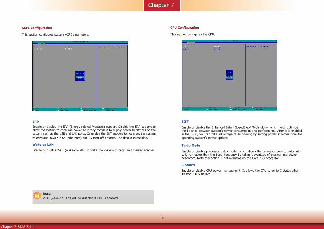
ACPI Configuration
This section configures system ACPI parameters.
ERPEnable or disable the ERP (Energy-related Products) support. Disable the ERP support to allow the system to consume power so it may continue to supply power to devices on the system such as the USB and LAN ports. Or enable the ERT support to not allow the system to consume power in S4 (hibernate) and S5 (soft-off ) states. The default is enabled.
Wake on LAN
Enable or disable WOL (wake-on-LAN) to wake the system through an Ethernet adapter.
CPU Configuration
This section configures the CPU.
EIST
Enable or disable the Enhanced Intel® SpeedStep® Technology, which helps optimize the balance between system’s power consumption and performance. After it is enabled in the BIOS, you can take advantage of its offering by setting power schemes from the operating system’s power options.
Turbo Mode
Enable or disable processor turbo mode, which allows the processor core to automati-cally run faster than the base frequency by taking advantage of thermal and power headroom. Note this option is not available on the Core™ i3 processor.
C-States
Enable or disable CPU power management. It allows the CPU to go to C states when it’s not 100% utilized.
Note:WOL (wake-on-LAN) will be disabled if ERP is enabled.

Chapter 7
Chapter 7 BIOS Setup
31
Video Configuration
This section configures the video settings.
Primary Display
Select the primary display for the system from the following options:
IGD: integrated graphics devices
PCIe: PCIe graphics devices
Integrated Graphics Device
Enable or disable the integrated graphics device.
Audio Configuration
This section configures the audio settings.
Audio Controller
Control the detection of the high-definition audio devices.
Disabled High-definition audio devices will be unconditionally disabled.
EnabledHigh-definition audio devices will be unconditionally enabled.

Chapter 7
Chapter 7 BIOS Setup
32
SATA Controller
Enable or disable the Serial ATA controller.
SATA Configuration
This section configures SATA devices. It also shows the information about the installed SATA drives.
SATA Speed Selection
Select Serial ATA device speed from these options: Gen1 (1.5 Gbit/s), Gen2 (3 Gbit/s) or Gen 3 (6 Gbit/s).
SATA Mode Selection
The mode selection determines how the SATA controller(s) operates.
AHCI Mode This option shows that the Serial ATA devices use AHCI (Advanced Host Controller Interface).
Serial ATA Port 0 and 1 and Hot Plug
Enable or disable each Serial ATA port and its hot plug function.
SATA Port 0: It controls the signal of the Mini PCIe card slot.SATA Port 1: It controls the signal of the M.2 Type 2242 slot.

Chapter 7
Chapter 7 BIOS Setup
33
PCI Express Configuration
This section configures the settings of PCI Express root ports.
PCI Express Root Port 1
Controls the PCIe signal of the M.2 Type 2242 B-key slot.
PCI Express Root Port 3
Controls the PCIe signal of LAN Port 1.
PCI Express Root Port 4
Controls the PCIe signal of LAN Port 2.
PCI Express Root Port 5
Controls the PCIe signal of the Mini PCIe slot.
PCI Express Root Port 6
Controls the PCIe signal of the M.2 Type 2230 E-key slot.
Press “Enter” to enter the configurations for each PCIe root port as shown on the right.
PCI Express Root Port
Enable or disable this PCI Express root port.
Hot Plug
Enable or disable the hot plug function.
PCIe Speed
Select the speed of the PCI Express Root Port: Auto, Gen1 (2.5 GT/s) or Gen2 (5 GT/s).

Chapter 7
Chapter 7 BIOS Setup
34
Console Redirection
Console redirection lets you monitor and control the system from a remote station by re-direct-ing the host screen output through a serial port.
Console Serial Redirect
Enable or disable the console redirection function. (The default is disabled.) If you select to enable it, please configure the following parameters for serial communication between the system and a remote station:
Terminal type: VT_100, VT_100+, VT_UTF8, or PC_ANSI.Baud rate: 115200, 57600, 38400, 19200 and 9600.Data bits: 8 bits or 7 bits.Parity: None, Even or Odd.Stop bits: 1 bit or 2 bits.Flow control: None, RTS/CTS or XON/XOFF
This is the global setting for all of the designated serial ports for the console redirection function.
COM A and COM BEnable or disable the serial redirection function for each of the serial ports on the sys-tem. The default is enabled for COM A and disabled for COM B. And configure the serial communication parameters to be used between the system and a remote station.
UseGlobalSetting
Choose to use the pre-configured global settings from the previous menu or configure a different setting for each serial port.

Chapter 7
Chapter 7 BIOS Setup
35
COM Port 1 and COM Port 2
Enable or disable each serial port.
Disable Disable this serial port.Enable Enable this serial port.
It also shows the Base I/O address and the assigned interrupt number.
Type
Choose RS232, RS422 or RS485 (Peer-to-Peer) for the serial communication type for COM port 1 and 2.
WDT
Enable or disable the watchdog function. A counter will appear if you select to enable WDT. Input any value between 1 and 255 (seconds).
AC Power LossSet the AC power loss to Always off or Always on. When set to Always off, the system’sstatus will be power-off after an AC power loss event. When set to Always on, the system’s status will be power-on after an AC power loss event.
Super I/O
This section configures the system super I/O chip parameters.
PC Health Status
This section displays PC health status.

Chapter 7
Chapter 7 BIOS Setup
36
SecurityThis section configures the Trusted Platform Module (TPM) function.
TPM Availability
Show or hide TPM availability and its configurations.
TPM Operation
Select one of the supported operation: Enable, Disable, or No Operation.
No Operation: No changes to the current state. Disable: Disable and deactivate TPM. Enable: Enable and activate TPM.
Set Supervisor Password
Set the administrative password for entering the BIOS utility or upon the entering of the power-on self-test (POST) process. The length of the password must be greater than 1 character and less than or equal to 10 characters.
Clear TPMRemove all TPM ownership contents.

Chapter 7
Chapter 7 BIOS Setup
37
Boot
Setup Prompt Timeout
Select the number of seconds the system will wait before booting the original firmware selection.
NumLock State
This allows you to determine the default state of the numeric keypad at boot. By default, the system boots up with Num Lock on. When set to Off, the function of the numeric keypad is the arrow keys.
Quiet Boot
Enable or disable the quiet boot function to configure the screen’s display between text messages or the OEM logo at bootup. Select Disabled to display the text messages. Select Enabled to display the OEM logo.
Network Stack
Enable or disable network stack. It supports the operation of these functions or software: Windows 8 BitLocker Network Unlock and UEFI IPv4/IPv6 PXE.
Note:The BIOS supports only UEFI boot but not legacy.
EFIEnter this menu to select the priority of the UEFI boot devices. Use the “+” key to move an item up or the “-” key to move an item down. The one on the top of the list has the highest priority.
PXE Boot Capability
Enable or disable Preboot eXecution Environment (PXE) boot through an Ethernet port. This function can only be enabled if the Network Stack support is enabled.
USB Boot
Enable or disable USB boot from a flash drive.

Chapter 7
Chapter 7 BIOS Setup
38
Exit
Exit Saving Changes
Select this field and press <Enter> to exit BIOS setup and save your changes.
Load Optimal Defaults
Select this field and press <Enter> to load the optimal defaults.
Discard Changes
Select this field and press <Enter>to exit the BIOS setup without saving your changes.
Save Setting to file
Select this option to save BIOS configuration settings to a USB drive. The operation will fail if there aren’t any USB devices detected on the system. The saved configuration will have the DSF file extension and can be used for restoration.
Restore Setting from fileSelect this option to restore BIOS configuration settings from a USB drive. Note that this option will not be available if there aren’t any USB devices detected in the system.

Chapter 7
Chapter 7 BIOS Setup
39
Updating the BIOSTo update the BIOS, you will need the new BIOS file and a flash utility. Please contact techni-cal support or your sales representative for the files and specific instructions about how to update BIOS with the flash utility. When you download the given BIOS file, you may find a BIOS flash utility attached with the BIOS file. This is the utility for performing BIOS updating procedure. For your convenience, we will also provide you with an auto-execution file in the BIOS file downloaded. This auto-execu-tion file will bring you directly to the flash utility menu soon after system boots up and finishes running the boot files in your boot disk.
||
||
Notice: BIOS SPI ROM1. The Intel® Management Engine has already been integrated into this system board. Due to
safety concerns, the BIOS (SPI ROM) chip cannot be removed from this system board and used on another system board of the same model.
2. The BIOS (SPI ROM) on this system board must be the original equipment from the factory and cannot be used to replace one which has been utilized on other system boards.
3. If you do not follow the methods above, the Intel® Management Engine will not be updated and will cease to be effective.
Note:a. You can take advantage of flash tools to update the default configuration of the BIOS (SPI ROM) to the latest version anytime.b. When the BIOS IC needs to be replaced, you have to populate it properly onto the
system board after the EEPROM programmer has been burned and follow thetechnical person's instructions to confirm that the MAC address should be burned or not.
RRead file successfully. (path= “platform.ini”)
Insyde H20FFT (Flash Firmware Tool) Version (SEG) 100.00.08.10Copyright(c) 2012 - 2016, Insyde Software Corp. All Rights Reserved.
Initializing Current BIOS Model name: AL551 New BIOS Model name: AL551 Current BIOS version: 68.08A New BIOS version: 68.08A Updating Block at FFFFF000h 0% 25% 50% 75% 100% 100%C:\SU25x>_
InformationPlease do not remove the AC power

www.dfi.com
40
Chapter 8
Chapter 8 Supported Software
The DVD that came with the system board contains drivers, utilities and software applications required to enhance the performance of the system board.
Insert the DVD into a DVD-ROM drive. The auto-run screen will appear. If the “Auto-run” does not automatically start, please go directly to the root directory of the DVD and double-click “Setup”.
Chapter 8 - Supported Software
For Windows 10

www.dfi.com
41
Chapter 8
Chapter 8 Supported Software
Intel Chipset Software Installation Utility
The Intel Chipset Device Software is used for updating Windows® INF files so that the Intel chipset can be recognized and configured properly in the system.
To install the utility, click “Intel Chipset Software Installation Utility” on the main menu.
1. Setup is ready to install the utility. Click “Next” to continue.
2. Read the license agreement and then click “Yes”.
3. Go through the readme docu-ment for more installation tips and then click “Next”.
4. Click “Finish” to exit setup.

www.dfi.com
42
Chapter 8
Chapter 8 Supported Software
Intel Graphics Drivers
To install the driver, click “Intel Graphics Drivers” on the main menu.
1. Setup is now ready to install the graphics driver. Click “Next” to continue.
By default, the “Automatically run WinSAT and enable the Windows Aero desktop theme” is enabled. With this enabled, after the graphics driver is installed and the system is rebooted, the screen will turn blank for 1 to 2 minutes (while WinSAT is running) before the Windows 7/Windows 8.1/Windows 10 desktop appears. The “blank screen” period is the time Windows is testing the graphics performance.
2. Read the license agreement and then click “Yes”.
4. Setup is now installing the driver. Click “Next” to con-tinue.
3. Go through the readme docu-ment for system requirements and installation tips and then click “Next”.
5. Click “Yes, I want to restart this computer now” and then click “Finish”.
Restarting the system will allow the new software instal-lation to take effect.

www.dfi.com
43
Chapter 8
Chapter 8 Supported Software
Audio Drivers
To install the driver, click “Audio Drivers” on the main menu.
2. Click “Yes, I want to restart my computer now” and then click “Fin-ish”.
Restarting the system will allow the new software installation to take effect.
1. Setup is ready to install the driver. Click “Next” to continue.
Intel LAN Drivers To install the driver, click “Intel LAN Drivers” on the main menu.
1. Setup is ready to install the driver. Click “Next” to continue.
2. Read and License Agreement and click “I accept the terms in the license agreement” if you agree the terms in the agreement, and then click “Next”.
3. Select the program features you want to install and then click “Next”.

www.dfi.com
44
Chapter 8
Chapter 8 Supported Software
4. Click “Install” to begin the installation.
5. After the installation is complete, click “Finish” to exit setup.
Adobe Acrobat Reader 9.3To install the reader, click “Adobe Acrobat Reader 9.3” on the main menu.
1. Click Next to install or click Change Destination Folder to select another folder.
2. Click “Install” to begin instal-lation.
3. Click “Finish” to exit setup.

www.dfi.com
45
Chapter 8
Chapter 8 Supported Software
4. Setup is ready to install the driver. Click “Next” to begin the installa-tion.
3. Read the file information and then click “Next”.
IO DriverTo install the driver, click “IO Driver” on the main menu.
1. Setup is ready to install the driver. Click “Next” to continue.
2. Read the license agreement carefully.
Click “I accept the terms in the License Agreement” if you agree with the terms in the agreement and then click “Next”.

www.dfi.com
46
Chapter 8
Chapter 8 Supported Software
5. Setup is now installing the driver.
6. Click “Finish” to exit setup.
Intel Trusted Execution Engine DriverTo install the driver, click “Intel Trusted Execution Engine Driver” in the main menu.
1. Select “I accept the terms in the License Agreement“ then click “Next.”
2. The screen shows the com-ponents that will be installed. Click “Next” to continue.

www.dfi.com
47
Chapter 8
Chapter 8 Supported Software
3. The screen displays the installation status in progress.
4. Click “Finish“ when the installation is complete.