ece 211 july 2010 edition-final - clemson university · ece 2110 - electrical engineering lab i . a...
TRANSCRIPT

LABORATORY MANUAL ECE 2110 - Electrical Engineering Lab
I
A companion course with ECE 2020 - Electric Circuits
I
Clemson University Holcombe Department of
Electrical and Computer Engineering Clemson, SC 29634
Revised July 2010
Dr. J. E. Harriss

Clemson University ECE
Page ii July 2010 Edition
Revision Notes 2005 Author: O. C. Parks. Revised from earlier editions.
2010 Revised April-May 2010 by Dr. James E. Harriss. Minor corrections (typos, table labels, etc.). Revise Lab 2 for better introduction to the NI-ELVIS II. Reduce voltage in Lab 2, step 4 to avoid equipment damage. Revise Lab 10 for better clarity and to reduce measurement errors. Changed terms throughout (especially Lab 8) to conform to NI- ELVIS II. Change from PSpice to LT Spice. Minor revision in Appendix C. Add Revision Notes.
2010 Revised July 2010 by Dr. James E. Harriss. Eliminate Lab 12 (Lab Review and Presentations) to reduce the number of lab meetings to better fit the semester schedule. Change Lab 4 (LT Spice) Procedure 4 to illustrate the effect of component tolerance on circuit measurements. Move former Lab 5 (Statistical Analysis) to a later point in the course.

Clemson University ECE
Page iii July 2010 Edition
Contents Part I Course Information ............................................................................................................. iv
Introduction ............................................................................................................................. v Student Responsibilities ...................................................................................................... v Laboratory Teaching Assistant Responsibilities ................................................................. v Faculty Coordinator Responsibilities .................................................................................. v Lab Policy and Grading: .................................................................................................... vi Course Goals and Objectives ............................................................................................. vi
Use of Laboratory Instruments............................................................................................. viii Laboratory Notebooks and Reports ........................................................................................ x
The Laboratory Notebook: .................................................................................................. x The Lab Report ................................................................................................................... x Format of Lab Report ......................................................................................................... xi
Part II Laboratory Meetings ........................................................................................................... 0 Laboratory 1 Orientation ....................................................................................................... 1 Laboratory 2 Workstation Characteristics ............................................................................ 2 Laboratory 3 DC Measurements ........................................................................................... 8 Laboratory 4 Introduction to LT Spice ................................................................................... 11 Laboratory 5 Network Theorems I...................................................................................... 15 Laboratory 6 Network Theorems II .................................................................................... 19 Laboratory 7 The Oscilloscope ........................................................................................... 21 Laboratory 8 RC and RL Circuits ....................................................................................... 24 Laboratory 9 Series RLC Circuits ....................................................................................... 27 Laboratory 10 Statistical Analysis ....................................................................................... 31 Laboratory 11 Design Lab ................................................................................................... 33 Laboratory 12 Final Exam ................................................................................................... 35
Part III Appendices ...................................................................................................................... 36 Appendix A: Safety ............................................................................................................. 37 Appendix B: Fundamentals of Electrical Measurements ..................................................... 41 Appendix C: Fundamentals of Statistical Analysis ............................................................. 50 Appendix D: Resistor Identification .................................................................................... 58

Clemson University ECE
Page iv July 2010 Edition
Part I Course Information

Clemson University ECE
Page v July 2010 Edition
Introduction
Introduction
This course is intended to enhance the learning experience of the student in topics encountered in ECE 2020. In this lab, students are expected to get hands-on experience in using the basic measuring devices used in electrical engineering and in interpreting the results of measurement operations in terms of the concepts introduced in the first electrical circuits course. How the student performs in the lab depends on his/her preparation, participation, and teamwork. Each team member must participate in all aspects of the lab to insure a thorough understanding of the equipment and concepts. The student, lab teaching assistant, and faculty coordinator all have certain responsibilities toward successful completion of the lab's goals and objectives.
Student Responsibilities:
The student is expected to be prepared for each lab. Lab preparation includes reading the lab experiment and related textbook material. If you have questions or problems with the preparation, contact your Laboratory Teaching Assistant (LTA), but in a timely manner. Don't wait until an hour or two before and then expect to find the LTA immediately available. Active participation by each student in lab activities is expected. The student is expected to ask the teaching assistant any questions he/she may have. DO NOT MAKE COSTLY MISTAKES BECAUSE YOU DID NOT ASK A SIMPLE QUESTION. A large portion of the student's grade is determined in the comprehensive final exam, so understanding the concepts and procedure of each lab is necessary for successful completion of the lab. The student should remain alert and use common sense while performing a lab experiment. He/she is also responsible for keeping a professional and accurate record of the lab experiments in a laboratory notebook. Students should report any errors in the lab manual to the teaching assistant.
Laboratory Teaching Assistant Responsibilities:
The Laboratory Teaching Assistant (LTA) shall be completely familiar with each lab prior to class. The LTA shall provide the students with a syllabus and safety review during the first class. The syllabus shall include the LTA's office hours, telephone number, and the name of the faculty coordinator. The LTA is responsible for insuring that all the necessary equipment and/or preparations for the lab are available and in working condition. LAB EXPERIMENTS SHOULD BE CHECKED IN ADVANCE TO MAKE SURE EVERYTHING IS IN WORKING ORDER. The LTA should fully answer any questions posed by the students and supervise the students performing the lab experiments. The LTA is expected to grade the lab notebooks and reports in a fair and timely manner. The reports should be returned to the students in the next lab period following submission. The LTA should report any errors in the lab manual to the faculty coordinator.
Faculty Coordinator Responsibilities:
The faculty coordinator should insure that the laboratory is properly equipped, i.e., that the teaching assistants receive any equipment necessary to perform the experiments. The coordinator is responsible for supervising the teaching assistants and resolving any questions or problems that are identified by the teaching assistants or the students. The coordinator may supervise the
Clemson University ECE
Page vi July 2010 Edition
Introduction
format of the final exam for the lab. He/she is also responsible for making any necessary corrections to this manual. The faculty coordinator is responsible for insuring that the software version of the manual is continually updated and available.
Lab Policy and Grading:
The student should understand the following policy: ATTENDANCE: Attendance is mandatory and any absence must be for a valid excuse and must be documented. If the instructor is more than 15 minutes late, students may leave the lab.
LAB RECORDS: The student must:
1) Keep all work in preparation of and obtained during lab in an approved NOTEBOOK; and
2) Prepare a lab report on selected experiments.
GRADING POLICY: The final grade of this course is determined using the following criterion:
Laboratory notebook and in-class work: 40%
Lab reports: 40%
Final exam: 20% In-class work will be determined by the teaching assistant, who, at his/her discretion may use team evaluations to aid in this decision. The final exam should contain a written part and a practical (physical operations) part.
PRE-REQUISITES AND CO-REQUISITES: The lab course is to be taken during the same semester as ECE 2020, but receives a separate grade. If ECE 2020 is dropped, then ECE 2110 must be dropped also. Students are required to have completed both MTHSC 108 and PHYS 122 with a C or better grade in each. Students are also assumed to have completed a programming class and be familiar with the use of a computer-based word processor.
THE INSTRUCTOR RESERVES THE RIGHT TO ALTER ANY PART OF THIS INFORMATION AT HIS/HER DISCRETION IF CIRCUMSTANCES SHOULD DICTATE. Any changes should be announced in class and distributed in writing to the students prior to their effect.
Course Goals and Objectives:
The Electrical Circuits Laboratory I is designed to provide the student with the knowledge to use basic measuring instruments and techniques with proficiency. These techniques are designed to complement the concepts introduced in ECE 2020. In addition, the student should learn how to record experimental results effectively and present these results in a written report. More explicitly, the class objectives are:

Clemson University ECE
Page vii July 2010 Edition
Introduction
1) To gain proficiency in the use of common measuring instruments. 2) To enhance understanding of basic electric circuit analysis concepts including:
a) Independent and dependent sources. b) Passive circuit components (resistors, capacitors, inductors, and switches).
c) Ohm's law, Kirchhoff's voltage law, and Kirchhoff's current law. d) Power and energy relations.
e) Thévenin's theorem and Norton's theorem. f) Superposition.
3) To develop communication skills through: a) Maintenance of succinct but complete laboratory notebooks as permanent, written
descriptions of procedures, results, and analyses. b) Verbal interchanges with the laboratory instructor and other students.
c) Preparation of succinct but complete laboratory reports. 4) To compare theoretical predictions with experimental results and to resolve any apparent
differences.

Clemson University ECE
Page viii July 2010 Edition
Use of Laboratory Instruments
Use of Laboratory Instruments One of the major goals of this lab is to familiarize the student with the proper equipment and techniques for making electrical measurements. Some understanding of the lab instruments is necessary to avoid personal or equipment damage. By understanding the device's purpose and following a few simple rules, costly mistakes can be avoided.
Ammeters and Voltmeters:
The most common measurements are those of voltages and currents. Throughout this manual, the ammeter and voltmeter are represented as shown in Figure 1.
Figure 1 - Ammeter and voltmeter. Ammeters are used to measure the flow of electrical current in a circuit. Theoretically, measuring devices should not affect the circuit being studied. Thus, for ammeters, it is important that their internal resistance be very small (ideally near zero) so they will not constrict the flow of current. However, if the ammeter is connected across a voltage difference, it will conduct a large current and damage the ammeter. Therefore, ammeters must always be connected in series in a cir- cuit, never in parallel with a voltage source. High currents may also damage the needle on an analog ammeter. The high currents cause the needle to move too quickly, hitting the pin at the end of the scale. Always set the ammeter to the highest scale possible, then adjust downward to the appropriate level.
Voltmeters are used to measure the potential difference between two points. Since the voltmeter should not affect the circuit, the voltmeters have very high (ideally infinite) impedance. Thus, the voltmeter should not draw any current, and not affect the circuit.
In general, all devices have physical limits. These limits are specified by the device manufacturer and are referred to as the device rating. The ratings are usually expressed in terms of voltage limits, current limits, or power limits. It is up to the engineer to make sure that in device operation, these ratings (limit values) are not exceeded. The following rules provide a guideline for instrument protection.

Use of Laboratory Instruments
Clemson University ECE
Page ix July 2010 Edition
Instrument Protection Rules:
1) Set instrument scales to the highest range before applying power. 2) Be sure instrument grounds are connected properly. Avoid accidental grounding of "hot" leads, i.e., those that are above ground potential.
3) Check polarity markings and connections of instruments carefully before connecting power.
4) Never connect an ammeter across a voltage source. Only connect ammeters in series with loads.
5) Do not exceed the voltage and current ratings of instruments or other circuit elements. This particularly applies to wattmeters since the current or voltage rating may be exceeded with the needle still on the scale.
6) Be sure the fuse and circuit breakers are of suitable value. When connecting electrical elements to make up a network in the laboratory, it is easy to lose track of various points in the network and accidently connect a wire to the wrong place. A procedure to follow that helps to avoid this is to connect the main series part of the network first, then go back and add the elements in parallel. As an element is added, place a small check by it on your circuit diagram. Then go back and verify all connections before turning on the power. One day someone's life may depend upon your making sure that all has been done correctly.
Clemson University ECE
Page x July 2010 Edition
Laboratory Notebooks and Reports
Laboratory Notebooks and Reports The Laboratory Notebook:
The student records and interprets his/her experiments via the laboratory notebook and the laboratory report. The laboratory notebook is essential in recording the methodology and results of an experiment. In engineering practice, the laboratory notebook serves as an invaluable reference to the technique used in the lab and is essential when trying to duplicate a result or write a report. Therefore, it is important to learn to keep an accurate notebook. The laboratory notebook should
1) Be kept in a sewn and bound or spiral bound notebook.
2) Contain the experiment's title, the date, the equipment and instruments used, any pertinent circuit diagrams, the procedure used, the data (often in tables when several measurements have been made), and the analysis of the results.
3) Contain plots of data and sketches when these are appropriate in the recording and analysis of observations.
4) Be, an accurate and permanent record of the data obtained during the experiment and the analysis of the results. You will need this record when you are ready to prepare a lab report.
The Lab Report:
The laboratory report is the primary means of communicating your experience and conclusions to other professionals. In this course you will use the lab report to inform your LTA what you did and what you have learned from the experience. Engineering results are meaningless unless they can be communicated to others.
Your laboratory report should be clear and concise. The lab report shall be typed on a word processor. As a guide, use the format on the next page. Use tables, diagrams, sketches, and plots, as necessary to show what you did, what was observed, and what conclusions you draw from this. Even though you will work with one or more lab partners, your report will be the result of your individual effort in order to provide you with practice in technical communication.
You will be directed by your LTA to prepare a lab report on a few selected lab experiments during the semester. Your assignment might be different from your lab partner's assignment.

Clemson University ECE
Page xi July 2010 Edition
Laboratory Notebooks and Reports
Format of Lab Report: NAME - Give your name.
LABORATORY XX TITLE
(Indicate the lab title and number)
LAB PARTNER(S) - Specify your lab partner's name. DATE - Indicate the date the lab was performed.
OBJECTIVE - Clearly state the objective of performing the lab.
EQUIPMENT USED - Indicate which equipment was used in performing the experiment. The manufacturer and model number should be specified.
PROCEDURE - Provide a concise summary of the procedure used in the lab. Include any modifications to the experiment.
DATA - Provide a record of the data obtained during the experiment. Data should be retrieved from the lab notebook and presented in a clear manner using tables.
OBSERVATIONS AND DISCUSSIONS - The student should state what conclusions can be drawn from the experiment. Plots, charts, other graphical medium, and equations should be employed to illustrate the student's viewpoint. Sources of error and percent error should be noted here.
QUESTIONS - Questions pertaining to the lab may be answered here. These questions may be answered after the lab is over.
CONCLUSIONS - The student should present conclusions which may be logically deduced from his/her data and observations.
SIGNATURE - Sign your report at the end. Include the statement - "This report is accurate to the best of my knowledge and is a true representation of my laboratory results."

Clemson University ECE
July 2010 Edition
Part II Laboratory Meetings

Laboratory 1: Orientation
Clemson University ECE
Page 1 July 2010 Edition
Introduction:
Laboratory 1 Orientation
In the first lab period, the students should become familiar with the location of equipment and components in the lab, the course requirements, and the teaching instructor. Students should also make sure that they have all of the co-requisites and pre-requisites for the course at this time.
Objective: To familiarize the students with the lab facilities, equipment, standard operating procedures, lab safety, and the course requirements.
Preparation: Read the introduction and Appendix A, Safety, in this manual.
Equipment Needed: ECE 2110 lab manual.
Procedure:
1) During the first laboratory period, the instructor will provide the students with a general idea of what is expected from them in this course. Each student will receive a copy of the syllabus, stating the instructor's office hours and telephone number. In addition, the instructor will review the safety concepts of the course.
2) The instructor will indicate which word processor should be used for the lab reports. The
students should familiarize themselves with the preferred word processor software. 3) During this period, the instructor will briefly review the equipment which will be used
throughout the semester. The location of instruments, equipment, and components (e.g. resistors, capacitors, connecting wiring) will be indicated. The guidelines for instrument use will be reviewed.
Probing Further: 1) During the next period, the instructor may ask questions or give a quiz to determine if you have read the introductory material. As a professional engineer, it will be your responsibility to prepare yourself to do your job correctly. Learn as much as you can "up front”. You will find that as a practicing professional if you wait until the last minute, you might have to pay a very painful price emotionally, financially, and professionally.
Report: No report is due next time.
Clemson University ECE
Page 2 July 2010 Edition
Laboratory 2: Workstation Characteristics
Introduction:
Laboratory 2 Workstation Characteristics
Every engineer relies on equipment to drive and measure an electrical system under study. These devices are rarely ideal, and have their own internal characteristics which must be considered. The internal characteristics of various devices often have a significant effect on circuit operation. This may be accounted for in circuit design and analysis to more adequately predict actual operation in the lab. Students and engineers should understand the internal characteristics of the equipment they are using. This experiment will explore some of those characteristics for the NI- ELVIS workstations used in this course.
Objective: By the end of this lab, the student should know how to determine the internal resistance of meters and sources. The student should understand how the internal resistance of these instruments affects the measurements.
Preparation: Reading: Read the section Use of Lab instruments and Appendix B, Fundamentals of Electrical Measurement, in this manual. Writing: In your laboratory notebook sketch the circuit diagram for each part of the procedure and create tables formatted to enter your data.
Equipment Needed: NI-ELVIS workstation. Resistance substitution box. Resistors: 1.0 kΩ
Procedure: Getting Started:
a. Turn on computer. b. Turn on NI-ELVIS power switch (right corner on the back). c. Turn on the NI-ELVIS Prototyping Board Power switch (at upper right corner, on top). d. Launch NI-ELVISMX INSTRUMENTS program. e. Launch the NI-ELVIS DMM instrument. f. Launch the NI-ELVIS VPS (Variable Power Supply) instrument. g. Arrange the instruments on the computer screen for your convenience. h. Set DMM to measure DC Volts. Specify the range to be 60V.
Note: The various range scales of voltmeters, ammeters, and similar measurement instruments are achieved by changing the internal resistances of the instruments. Therefore, when measuring the internal resistance of an instrument, it is important to set the

Clemson University ECE
Page 3 July 2010 Edition
Laboratory 2: Workstation Characteristics
+
– V
instrument’s range to one value and not change it until the measurements are completed. Therefore, choose a scale that will allow making the desired measurements.
1) NULL OFFSET for the voltmeter:
Electrical drift sometimes causes shifts in the ZERO point indicated by measurement instruments. Often the shift is inconsequential, but sometimes it is significant compared to the actual signal being measured. To eliminate the shift, the NI-ELVIS provides a NULL OFFSET function that subtracts the value indicated at the instant NULL OFFSET is turned on. This is just like subtracting the tare weight of a container on a laboratory balance before weighing a material.
To set the voltmeter’s NULL OFFSET: Plug leads into the DMM “VΩ” and “COM” jacks, clip the leads together, let the voltage reading stabilize, and turn on “Null Offset”.
2) Measure DC resistance of the DMM Voltmeter:
Voltmeters have an internal electrical resistance. Ideally a voltmeter would have infinite resistance, so no current would flow through it and so the meter would not affect voltages throughout the circuit. But real meters are not ideal. In this exercise you will measure the DC resistance of the DMM voltmeter.
a. Set the VPS “Supply +” voltage to +10.00 Volts. “STOP” the VPS. b. Set up the circuit as shown in Figure 2.1, using the NI-ELVIS DMM for the voltmeter
and the VPS for the power supply.
R
10V Voltmeter with internal resistance RVi
Figure 2.1 - Circuit diagram to measure the internal resistance of the voltmeter.
c. Set the resistor R to 0Ω by shorting the resistor’s leads. “RUN” the VPS and record the voltage indicated by the meter. Remove the short across R.
d. Increase the resistance R so that the meter reading drops by a significant fraction (up to about one half) of the original value. (Hint: R will need to be in the range of MΩ.) Record the final resistance R and measured voltage.
e. “STOP” the VPS. f. Use the DMM ohmmeter to measure the actual resistance R, rather than relying on the
indicated settings of the substitution box. Record the measured value. (Anytime you

Clemson University ECE
Page 4 July 2010 Edition
Laboratory 2: Workstation Characteristics
make such measurements, it may be instructive to record results at a few intermediate values of R as well, for corroborative calculations.)
g. From these readings, use voltage division to calculate RVi, the equivalent internal resistance of the voltmeter.
3) Measure DC resistance of the DMM Ammeter:
Ammeters also have an internal electrical resistance. Ideally an ammeter would have no resistance (0 Ω) so that it would not alter the current flow it is trying to measure. In this exercise you will measure the DC resistance of the real DMM ammeter. a. Set the VPS “Supply +” voltage to +10.00 Volts. “RUN” the VPS and measure the
actual voltage using the DMM voltmeter. Record the actual voltage. “STOP” the VPS. b. To use the DMM as an ammeter, move the DMM cables to “A” and “COM” and switch
the DMM to measure DC Amps. c. Set up the circuit as shown in Figure 2.2, using the NI-ELVIS DMM for the ammeter
and the VPS for the power supply.
1kΩ
+ 10V
–
Ammeter
with internal A R resistance RAi
Figure 2.2 - Circuit diagram to measure the internal resistance of the ammeter.
d. With the VPS STOPPED, null the ammeter display value to obtain a reasonable zero reading.
d. NULL the ammeter: Disconnect one lead of the ammeter (so no current will flow) and
null the ammeter display value to obtain a reasonable zero reading. Reconnect the ammeter lead to the circuit.
e. Set the resistor R to 1 MΩ resistance. “RUN” the VPS. In a table, record the resistance
R and the current indicated by the ammeter.
f. Adjust R to 100kΩ. In your table, record the resistance R and the current indicated by the ammeter.
g. Continue to decrease the resistance R until the ammeter reading drops by a significant fraction (up to about one half) of the original value. Record the final resistance R and measured current.

Clemson University ECE
Page 5 July 2010 Edition
Laboratory 2: Workstation Characteristics
h. Use the DMM ohmmeter to measure the actual final resistance R, rather than relying on the indicated settings of the substitution box. (You will need to connect the DMM cables to “VΩ” and “COM” for this measurement.)
i. From these readings, use current division to calculate RAi, the equivalent internal resistance of the ammeter.
4) Measure Output Resistance of VPS Supply +: Power sources also have internal resistance, which cause the units to get hot and which limit the amount of current the sources can deliver. The internal resistance may also be chosen to match a power source to the system it is powering. In this step you will measure the internal resistance of the NI-ELVIS’s variable power supply, VPS. a. STOP the VPS.
b. Set the VPS “Supply +” voltage to +0.5 Volts. c. Use the DMM to measure the actual voltage.
To do this, switch the DMM to DC V mode and choose AUTO Mode. Move the DMM leads to “VΩ” and “COM” and connect the DMM leads to SUPPLY + output and GROUND. “RUN” the VPS and measure the actual voltage with the DMM voltmeter. Record the actual voltage. “STOP” the VPS.
Note: If you null the voltmeter, be sure you do so by disconnecting the DMM leads from the circuit and shorting the leads together. Even with the VPS STOPPED, a small but significant voltage may exist. d. Construct the circuit shown in Figure 2.3.
0.5V
Figure 2.3 - Circuit diagram for measuring the internal resistance of the workstation power supply.
e. Adjust the resistor R to 10kΩ. “RUN” the VPS. Record the resistance R and the
measured voltage in a table.
f. Adjust the resistance R so that the meter reading drops by a significant fraction (up to about one half) of the original value. Record the R and V values in the table.
CAUTION: The resistors in the substitution box are rated to handle at most 0.3 Watt power (Power = V²/R). If you exceed that limit, you will likely damage both the resistors and the power supply.
R
VPS
RVPS
+
–
A

Clemson University ECE
Page 6 July 2010 Edition
Laboratory 2: Workstation Characteristics
2 2 2
g. From these readings, use voltage division to determine RVPS, the equivalent internal resistance of the voltage source VPS.
5) Measure Output Resistance of the Function Generator:
Repeat Part 4 using the Function Generator FGEN instead of VPS for the power source.
a. Construct the circuit shown in Figure 2.4.
Function Generator
Vp-p =
1.414 V
Figure 2.4 – Circuit diagram to measure internal resistance of the Function Generator FGEN.
b. Set the FGEN to output a sine wave with p-p amplitude of 1.41V and frequency 100 Hz.
c. Set the DMM to measure AC Volts. Keep in mind that the voltmeter’s display shows the value of RMS voltage, where for a sinusoidal waveform,
VRMS =
Vpeak = Vp− p .
d. Adjust the resistor R to 100 kΩ. “RUN” the FGEN. Record the resistance and the measured voltage in a table.
e. Adjust the resistance R so that the meter reading drops by a significant fraction (up to about one half) of the original value. Record the R and V values in the table.
f. From these readings, use voltage division to determine RFGEN, the equivalent internal resistance of the Function Generator.
Probing Further:
1) Based on your estimates of the internal resistance of the voltmeters and ammeters used in these experiments, what would be the values of internal resistance of these meters if, in each case, the range used had been a factor of 10 larger than the range you actually used? Refer to Appendix B for the equivalent circuit models of the meters to guide your thinking about the answer to this question.
2) Given your values for the internal resistances of the DC source and the function generator,
what do you think is the maximum amount of current that can be supplied by each source?
RFGEN
V R

Clemson University ECE
Page 7 July 2010 Edition
Laboratory 2: Workstation Characteristics
3) How does the voltmeter’s resistance affect measurements? Consider the circuit shown in Figure 2.5, and assume that the power supply is ideal.
100kΩ
+ 10V V R
–
Figure 2.5 - Circuit diagram for measurements to determine the effect of voltmeter internal resistance on measurement accuracy.
For resistance values R = 1kΩ, 100kΩ, and 10MΩ, calculate the voltage that would be displayed on an ideal voltmeter (i.e., if it had infinite resistance). Repeat the calculation using the real internal resistance you measured in step 2. Show your work in your lab book and display your results in a table such as shown here:
R(Ω) Videal Vreal
1 k 100 k 10 M
Briefly discuss the significance of these results.
Report:
Your Laboratory Teaching Assistant will inform you when a report is due, and on which experiment you will report. Make sure that you have recorded all necessary information and data in your laboratory notebook to enable you to prepare a report on this experiment, if so directed, at some time in the future.

Clemson University ECE
Page 8 July 2010 Edition
Laboratory 3: DC Measurements
Introduction:
Laboratory 3 DC Measurements
Voltage and current values may be used to determine the power consumed (or provided) by an electrical circuit. Electric power consumption is a very important factor in all electrical applications, ranging from portable computers to megawatt industrial complexes. Thus, an understanding of power and how it is measured is vital to all engineers.
Objective: By the end of this lab, the student should know how to make DC measurements of voltages and currents to determine power dissipation/delivery for circuit elements, branches, and various combinations of elements and branches.
Preparation: Read the introductory material in the ECE 2020 textbook describing the passive sign convention for circuit elements. Also, review the lab manual section Use of Laboratory Instruments. Prior to coming to lab class, calculate the values of voltage, current, and power absorbed/delivered for each circuit element in Figure 3.1 (i.e. do Part 0 of the Procedure). Also, sketch in your lab notebook the circuit diagrams to be used in each part of the procedure and have a table prepared for each part in order to record data.
Equipment Needed: NI-ELVIS workstation. Resistors as required.
Procedure: 0) For the circuit given in Figure 3.1, calculate the voltages across and currents through each
circuit element. Using these values, determine the power absorbed or delivered by each circuit element. Include your calculations in your laboratory notebook. Record all of your theoretical results in a table for later comparison with your experimental values.
Figure 3.1 - DC resistive network.

Clemson University ECE
Page 9 July 2010 Edition
Laboratory 3: DC Measurements
1) Set up the circuit in Figure 3.1. Adjust the output of the DC power supply to 10V and verify with the digital multimeter (DMM). Using the digital multimeter function in the NI-ELVIS workstation (set to measure DC Volts), measure the voltage across each individual circuit element. Before making each measurement, use the connection scheme shown in Figure 3.2 to verify that your voltmeter connection method is correct. Record the measurements in your laboratory notebook. For each measured voltage, determine the percent difference from the theoretical value determined in Part 0.
Figure 3.2 - Connection scheme for circuit voltage measurements. 2) For the circuit in Figure 3.1, measure the current through each circuit element using the digital
multimeter function in the NI-ELVIS workstation (set to measure DC Amps). Before each measurement, the circuit will have to be turned off and rewired to insert the ammeter in series with the component under test. Before making each measurement, use the connection scheme shown in Figure 3.3 to verify that your ammeter connection method is correct. Record the measurements in your laboratory notebook. For each measured current, determine the percent difference from the theoretical value determined in Part Ο.
Figure 3.3 - Connection scheme for circuit current measurements.

Clemson University ECE
Page 10 July 2010 Edition
Laboratory 3: DC Measurements
3) Using your measurements from Parts 1 and 2, calculate the power absorbed or delivered by each circuit element. Record these values in your laboratory notebook. Compare them with the values obtained through circuit analysis in Part 0. Calculate the percent difference from the theoretical values.
Probing Further:
1) What is the relationship between the power values obtained from your measured values of voltage and current and those calculated theoretically in Part 0? What do you think are sources of error? Explain.
2) How does the sum of power absorbed by the resistances in the circuit compare to the amount
delivered by the source?
Report:
Your Laboratory Teaching Assistant will inform you when a report is due, and on which experiment you will report. Make sure that you have recorded all necessary information and data in your laboratory notebook to enable you to prepare a report on this experiment, if so directed, at some time in the future.

Clemson University ECE
Page 11 July 2010 Edition
Laboratory 4: Introduction to LT Spice
Introduction:
Laboratory 4 Introduction to LT Spice
The widespread availability of computers has enabled the development of software which quite accurately models the behavior of electrical circuits. The most widely used program is SPICE, developed by the University of California-Berkeley in the mid-1970's and updated several times since then. Amongst the commercially available versions of SPICE is LT Spice from Beige Bag Software. LT Spice is loaded on the ECE 2110 laboratory computers, and a Lite version is available for free from the company (http://www.beigebag.com/adv4_lite.htm). As an introduction, you will learn to use LT Spice circuit simulation software with relatively simple circuits. Later, in the introductory electronics courses ECE 320 and ECE 321, you will learn to use LT Spice to simulate the operation of more advanced components such as diodes, transistors, and even a few integrated circuits.
Objective:
This lab should give the student a basic understanding of how to use LT Spice to simulate circuit operating conditions. After this lab, the student should be able to use LT Spice to solve or check basic circuit problems.
Preparation:
Prior to coming to lab class, calculate the voltages and currents for each resistor shown in the circuit of Figure 4.1 (i.e. do Part 0 of the Procedure).
Equipment Needed:
A computer with LT Spice loaded and ready to use.

Clemson University ECE
Page 12 July 2010 Edition
Laboratory 4: Introduction to LT Spice
Procedure:
0) Before coming to lab, determine the voltages across and currents through each resistor in the circuit of Figure 4.1.
Figure 4.1 - Resistive network for hand analysis and LT Spice simulation. 1) In the lab, your LTA will go through the guidelines for using computer equipment in a College
of Engineering & Science laboratory. Then the LTA will provide an introduction to the LT Spice software environment. During this instruction session, you will learn how to:
a) Open the software and create a new project.
b) Place circuit components in your project workspace.
c) Connect circuit components together.
d) Set up circuit measurements.
e) Change simulation execution settings.
f) Run simulations.
g) Display or export the simulation output.
One important principal to keep in mind is that if you want LT Spice to display a graph or a table of something, you must include a suitable measurement device (e.g., voltmeter or ammeter) for that value. Anything without a meter won’t be graphed.
2) Use LT Spice to solve for all of the resistor voltages and currents for the circuit of Figure 4.1.
Your problem solutions, using LT Spice, are to be turned in. Compare your simulation measurements with the results of your calculations in Part 0.
3) Use LT Spice to simulate the circuit used in Laboratory 3 (Figure 3.1). Determine the voltages
and currents for each circuit component. Your problem solutions, using LT Spice, are to be turned in.

Clemson University ECE
Page 13 July 2010 Edition
Laboratory 4: Introduction to LT Spice
4. Variability is inherent in any process, including the manufacture of resistors and capacitors. Such components are usually marked with a nominal (target) value and a tolerance within which the actual value might fall.
R1 1000
R3 510
Figure 4.2: LT Spice representation of the circuit of Figure 3.1
Consider the circuit of Figure 4.2 — the same circuit you simulated in Procedure 3 and measured in Laboratory 3. If the resistors you used in Laboratory 3 had a tolerance of 10%, their actual values might have been anywhere in the following ranges:
900Ω ≤ R1 ≤ 1100Ω 459Ω ≤ R2 ≤ 561Ω 459Ω ≤ R3 ≤ 561Ω
To understand how such variation might affect your measurements of current and voltage in an actual circuit, use LT Spice to calculate the currents and voltages if the resistors were at some of their extreme values, as indicated in the table below:
R1 R2 R3 I1 I2 I3 V1 V2
1100 459 561 900 459 561
1100 459 459 900 459 459
(I1, I2, and I3 are the currents through R1, R2, and R3. V1 is the voltage across R1 and V2 is the voltage across R2 and R3.)
Compare the voltages and currents of the last row (900Ω, 459Ω, and 459Ω) to the voltages and currents found in the simulation of Procedure 3 and explain your observations.
For an understanding how the variability of a process is characterized by measurement of the mean, the variance, and the standard deviation of a parameter, read Appendix C, Fundamentals of Statistical Analysis in this manual.
Probing Further:
1) How do the LT Spice simulation results in Part 1 compare to your calculations in Part 0? Can you account for any differences?
10V
V1 R2 510

Clemson University ECE
Page 14 July 2010 Edition
Laboratory 4: Introduction to LT Spice
2) How do the LT Spice simulation results of Procedure 3 compare to your measurements in Laboratory 3? Can you account for any differences?
Report:
The problem solutions are due the next period. Include a title page and a brief procedure for each circuit. Report the results from LT Spice, and highlight these results on the printouts. Include a circuit diagram with each problem. Problem statements, files, and printouts should be included at the end of the report.

Clemson University ECE
Page 15 July 2010 Edition
Laboratory 5: Network Theorems I
Introduction:
Laboratory 5 Network Theorems I
An understanding of the basic laws of electrical voltages and currents is essential to electrical engineering. Circuit analysis is dependent upon knowing the nature of the laws governing voltage and current characteristics. This lab studies Kirchhoff's Voltage Law, Kirchhoff's Current Law, voltage division, current division, and equivalent resistance.
Objective: By the end of this lab, the student should understand KVL, KCL, voltage division, current division, and equivalent resistance combinations.
Preparation: Read the material in the textbook that describes Kirchhoff's Voltage Law, Kirchhoff's Current Law, voltage division, current division, and equivalent resistance combinations. Be able to perform circuit calculations using these principles. Before coming to class, analyze each circuit and determine the theoretical values that should be obtained during the lab. Verify your calculations by performing LT Spice simulations for each circuit. Record both your calculations and simulation results in your laboratory notebook.
Equipment Needed: NI-ELVIS workstation. Individual resistors as required. Resistance substitution box.
Procedure: 1) Adjust the output of the DC power supply to 10V and verify with the digital multimeter. Set
up the circuit as shown in Figure 6.1. Measure and record the total current into the circuit. Using the measured current and voltage, determine the equivalent resistance of the parallel components in the circuit. Replace the resistors with a resistance substitution box set to the equivalent resistance and measure the current as before. Compare the experimentally determined equivalent resistance to the theoretical value.
Figure 6.1 - Determining parallel equivalent resistance.
Clemson University ECE
Page 16 July 2010 Edition
Laboratory 5: Network Theorems I
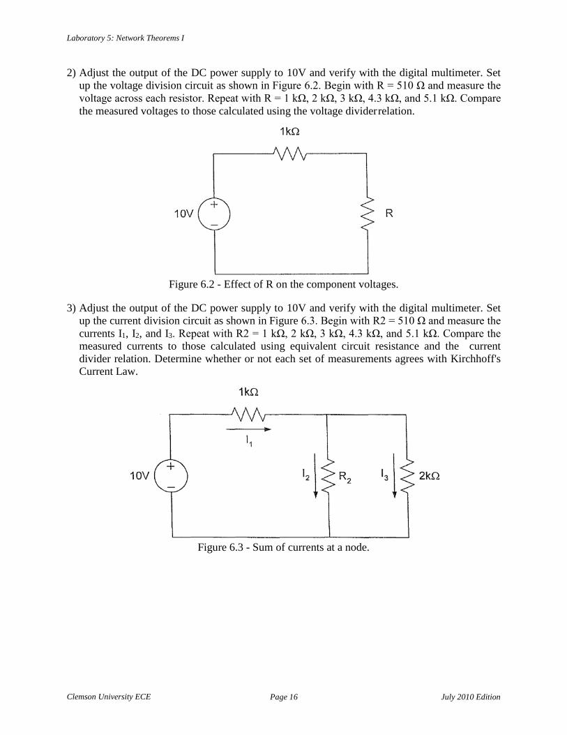
2) Adjust the output of the DC power supply to 10V and verify with the digital multimeter. Set up the voltage division circuit as shown in Figure 6.2. Begin with R = 510 Ω and measure the voltage across each resistor. Repeat with R = 1 kΩ, 2 kΩ, 3 kΩ, 4.3 kΩ, and 5.1 kΩ. Compare the measured voltages to those calculated using the voltage divider relation.
Figure 6.2 - Effect of R on the component voltages. 3) Adjust the output of the DC power supply to 10V and verify with the digital multimeter. Set
up the current division circuit as shown in Figure 6.3. Begin with R2 = 510 Ω and measure the currents I1, I2, and I3. Repeat with R2 = 1 kΩ, 2 kΩ, 3 kΩ, 4.3 kΩ, and 5.1 kΩ. Compare the measured currents to those calculated using equivalent circuit resistance and the current divider relation. Determine whether or not each set of measurements agrees with Kirchhoff's Current Law.
Figure 6.3 - Sum of currents at a node.

Clemson University ECE
Page 17 July 2010 Edition
Laboratory 5: Network Theorems I
4) Adjust the output of the DC power supply to 10V and verify with the digital multimeter. Set up the circuit as shown in Figure 6.4. Measure the voltage across each component. Compare the measured voltages to those calculated using the voltage divider relation. Determine whether or not your measurements agree with Kirchhoff's Voltage Law.
Figure 6.4 - Sum of voltages around a loop.
5) Adjust the output of the DC power supply to 10V and verify with the digital multimeter. Set up the circuit as shown in Figure 6.5. Measure the voltage across each component in loop 1. Repeat for loop 2 and loop 3. Compare your measured values with the terms in the KVL equation written for each loop. Determine whether or not your measurements agree with Kirchhoff's Voltage Law. Explain the reasons for any discrepancies found.
Figure 6.5 - Sum of voltages around different loops.

Clemson University ECE
Page 18 July 2010 Edition
Laboratory 5: Network Theorems I
Probing Further:
1) In part 2, what would the value of R have to be so that the voltage across R is 4/5 of the source voltage? Your answer should be quantitative (i.e. a number).
2) In part 3, what would the value of R2 have to be so that the current through R2 is 10 times the
current through R3? Your answer should be quantitative.
Report:
Your Laboratory Teaching Assistant will inform you when a report is due and on which experiment you will report. Make sure that you have recorded all necessary information and data in your laboratory notebook to enable you to prepare a report on this experiment, if so directed, at some time in the future.

Clemson University ECE
Page 19 July 2010 Edition
Laboratory 6: Network Theorems II
Introduction:
Laboratory 6 Network Theorems II
This lab focuses on the Thévenin equivalent and maximum power transfer theorems. Complex circuits are often replaced with their Thévenin equivalent to simplify analysis. For example, in the analysis of large industrial power systems the Thévenin equivalent is used in short circuit studies. Maximum power transfer is also an important concept which allows the designer to determine an optimal design when power is a constraint.
Objective: By the end of this lab, the student should be able to verify Thévenin's equivalence theorem and the concept of maximum power transfer.
Preparation: Read the material in the textbook that describes Thévenin's equivalence theorem and maximum power transfer.
Equipment Needed: NI-ELVIS workstation. Individual resistors as required. Resistance substitution box.
Procedure:
1) This part of the lab illustrates the use of Thévenin's theorem. Adjust the output of the DC power supply to 10V and verify with the digital multimeter. Set up the circuit as shown in Figure 7.1. Measure the open circuit voltage between nodes A and B. Measure the short circuit current between nodes A and B (i.e. connect the ammeter between nodes A and B). Using these measurements, determine the Thévenin equivalent circuit. Set up the newly determined Thévenin equivalent circuit and verify that this circuit has the same open circuit voltage and short circuit current as the previous circuit. Save this circuit for Part 2.
Figure 7.1 - Determining the Thévenin equivalent circuit.

Clemson University ECE
Page 20 July 2010 Edition
Laboratory 6: Network Theorems II
2) This part of the lab is to illustrate maximum power transfer. Use the Thévenin equivalent circuit developed in Part 1. For a resistance substitution box R between nodes A and B, measure the current through and voltage across R if R = 0Ω. Repeat for R = 100Ω, 120Ω, ..., 500Ω (in 20Ω increments). Determine the power dissipated by the resistor for each value of R. Plot power vs. resistance. At which value is the power a maximum?
Probing Further:
1) Use LT Spice to determine the Thévenin equivalent for the circuit in Part 1. First, enter the circuit shown in Figure 7.1 using node B as the reference or "ground" node. The voltage at node A is then the open circuit voltage. To measure the short-circuit current between points A and B, place an ammeter between the points. Determine the Thévenin equivalent and compare to your experimentally obtained equivalent circuit in Part 1. Record your LT Spice programs and the data obtained from the simulation in your laboratory notebook by pasting in the printouts. Highlight the open-circuit voltage value and short-circuit current value obtained from the simulation.
2) Use LT Spice to simulate the circuit of Part 2. Start with the value of R = Rmax_pwr that you
determined experimentally to give maximum power transfer and find, from the LT Spice simulation, the power delivered to this resistance. Then repeat with 20Ω increments through 100Ω (i.e. for Rmax_pwr – 100Ω < R < Rmax_pwr + 100Ω). Compare the values of power obtained by simulation with those you obtained experimentally. Record your LT Spice programs and the data obtained from them in your laboratory notebook.
Report: Your Laboratory Teaching Assistant will inform you when a report is due, and on which experiment you will report. Make sure that you have recorded all necessary information and data in your laboratory notebook to enable you to prepare a report on this experiment, if so directed, at some time in the future.

Clemson University ECE
Page 21 July 2010 Edition
Laboratory 7: The Oscilloscope
Introduction:
Laboratory 7 The Oscilloscope
The digital oscilloscope allows the engineer to examine time varying waveforms in order to determine the magnitude, frequency, phase angle, and other waveform characteristics which depend upon the interaction of circuit elements with the sources driving them.
Objective: By the end of the lab the student should be familiar with the controls of a digital oscilloscope and be able to use the instrument to observe periodic waveforms.
Preparation: Review 'XYZs of Oscilloscopes', available at: www.tek.com (60+ pages). Be familiar with the following: voltage scaling (Volts/division), time base (seconds/division), input coupling, triggering, and measurement probes.
Equipment Needed: NI-ELVIS workstation. Individual resistors as required.
Procedure:
0) At the beginning of class, your LTA will review the virtual oscilloscope software used with the NI-ELVIS workstation.
1) Basic setup. Connect a cable with BNC fitting to the BNC jack for CH 0 of the oscilloscope
on the left side of the NI-ELVIS II. Connect the cable’s red lead to the FGEN output; connect the cable’s black lead to GROUND. (Important note: Internally the oscilloscope’s ground is connected to the NI-ELVIS circuit ground, therefore, the oscilloscope can only measure voltages across components that are connected to ground. Avoid grounding errors!)
Set the function generator to output a 100Hz sine wave with amplitude = 3.0 VPP and DC offset = 0V. Open the oscilloscope window in the NI-ELVIS software. “ENABLE” the display for Channel 0. “RUN” the function generator and the oscilloscope. Turn on the measurement function for Channel 0 and record the measured values for RMS voltage, peak-to-peak voltage, and waveform frequency. Sketch the displayed waveform in your laboratory notebook. Compare your measurements with the expected values based on the function generator output.
2) Source control. Connect CH 0 to “SYNC” (adjacent to FGEN). Sketch this waveform in your
laboratory notebook. Reconnect CH 0 to FGEN. Change the function generator output to a square wave, record the displayed waveform in your laboratory notebook, and measure the peak-to peak output voltage. Repeat this measurement for a triangular wave.
Clemson University ECE
Page 22 July 2010 Edition
Laboratory 7: The Oscilloscope
3) Voltage scaling. Reset the function generator to output a sine wave. Vary the vertical scale control for Channel 0 using either the control knob or pull-down menu. Record the effect that this control has on the displayed waveform. Set the control to 500mV/div and measure the peak-to-peak magnitude of the displayed waveform by counting (estimate) the number of peak-to-peak divisions and multiplying by the vertical scale. Compare this result with the measurement given by the oscilloscope.
4) Voltage offset manipulation. Vary the vertical position control in the oscilloscope and record
the effects in your laboratory notebook, noting any changes in the measured RMS voltage. Return the offset to zero and add a DC offset of 0.5V to the function generator output. Record the effects in your laboratory notebook, noting any changes in the measured RMS voltage.
5) Time scaling. Return the DC offset in the function generator to 0V. Using either the timebase
dial or pulldown menu, adjust the timebase of the oscilloscope display to the fastest setting (5μS/div). Record the effect that this setting has on the displayed measurements for the waveform. Gradually increase the timebase through each available setting until the slowest setting has been reached (200mS/div). Record the effect that this control has on the measurement of voltage and frequency. Return the timebase to a setting where 1-3 full cycles of the output sine wave is viewable. Set the Acquisition Mode to ‘RUN ONCE’ and press ‘RUN’ to capture a single sweep of the output waveform and measure the period of the waveform by counting (estimate) the number of time divisions for a single cycle and multiplying by the time scale. Compare this measurement to the inverse of the frequency measured by the oscilloscope.
6) Triggering / synch function. Return the screen update to 'RUN'. Adjust the triggering pull-
down menu tο 'Edge' and record the oscilloscope response. Vary the function generator peak amplitude to verify that the oscilloscope is continuing to update the display in this mode of operation.
7) Cursor function. Set the function generator to output a 100Hz sine wave with peak amplitude
= 3.0 VPP and DC offset = 0V. Return the triggering function to 'Immediate'. Display a single screen update of between 1-3 cycles of the output function. Switch the cursors function on and drag the cursors to appropriate points on the waveform to measure the period of the sine wave. Then adjust the cursors to measure the peak-to-peak voltage of the sine wave. Compare these measurements to those expected based on the function generator's output settings.
8) Connect the voltage divider circuit shown in Figure 8.1. Set the function generator to output a
1kHz sine wave with amplitude = 2VPP and DC offset = 0. Display the function generator output on Channel 0 of the oscilloscope and the voltage across the 100Ω resistor on Channel 1. Be careful to avoid grounding errors. Display and measure these voltages simul- taneously. Measure the period of both waveforms using the cursor function. Sketch the waveforms in your laboratory notebook and record your settings for Volts/div and seconds/div. Compare your voltage measurements with theoretical calculations based on the voltage divider equation. Compare your waveform period measurement with the theoretical value obtained from the input frequency.

Clemson University ECE
Page 23 July 2010 Edition
Laboratory 7: The Oscilloscope
Figure 8-1. Voltage divider circuit used in Parts 8 and 9.
9) Reverse the polarity for the output voltage measurement on Channel 1. Repeat your voltage
and period measurements as in Part 8, sketch the resulting waveforms in your laboratory notebook, and record your settings for Volts/div and seconds/div.
Probing Further:
1) What purpose does the FGEN’s ‘SYNC’ serve? 2) Why does the RMS voltage measurement vary when an offset is added in the function
generator but not when changed in the oscilloscope? 3) In Part 9, what effect did reversing the polarity of the output voltage measurement have on the
oscilloscope display and the oscilloscope voltage measurements? 4) How is the accuracy of your measurements affected by adjustment of the volts/division
control? Seconds/division control? 5) How would the peak-to-peak and RMS voltage measurements be affected by the presence of
noise in a displayed waveform? Would this be a clear representation of the actual signals in a circuit? What steps would you take to determine if noise is an issue in your oscilloscope measurements and how would you mitigate it, if necessary?
Report: Your Laboratory Teaching Assistant will inform you when a report is due, and on which experiment you will report. Make sure that you have recorded all necessary information and data in your laboratory notebook to enable you to prepare a report on this experiment, if so directed, at some time in the future.

Clemson University ECE
Page 24 July 2010 Edition
Laboratory 8: RC and RL Circuits
Introduction:
Laboratory 8 RC and RL Circuits
This lab deals with RC and RL circuits. RC and RL circuits are used in many configurations for a large variety of design purposes. In addition, real components can be modeled in a given frequency range by a combination of R and C or R and L, as appropriate. For example, a wirewound resistor can be modeled as a "pure" resistor, R, at DC or very low frequencies, but as the frequency of operation increases, the inductive effects of the winding must be taken into account. This lab illustrates some of the basic features of the transient response of circuits in which resistance and capacitance or resistance and inductance are both present.
Objective: By the end of this lab, the student should know how to measure the time constants of RC and RL circuits.
Preparation: Review the material in the textbook on RC and RL circuits. Before coming to the lab, determine the theoretical time constants of the circuits used in the lab. Be sure to account for the 150Ω output impedance of the function generator in your calculations.
Equipment Needed: NI-ELVIS workstation. Resistance substitution box Capacitance substitution box Inductance substitution box
Procedure:
1) Set up the RC circuit shown in Figure 9.1. Set the function generator to give a square wave output with magnitude equal to 500mV. Measure both the source voltage and the voltage across the capacitor with the digital oscilloscope. (Avoid grounding errors!) Adjust the frequency of the function generator so that the waveform shown has definite flat sections at the top and bottom. Using the oscilloscope cursors function, determine when the voltage reaches 0.632 times its final value. Sketch the waveform for a complete cycle in your notebook, recording the voltage scale and time scale values. Clearly label the sketched waveforms, including initial and final values. Repeat these steps using C = 0.047 μF and C = 0.1 μF. For each circuit the frequency of the waveform generator may have to be changed to achieve the flat sections at top and bottom of the waveforms.

Clemson University ECE
Page 25 July 2010 Edition
Laboratory 8: RC and RL Circuits
Figure 9.1 - RC circuit. 2) Now modify the circuit of Figure 9.1 by swapping the positions of the resistor and capacitor.
Repeat the measurements in Part 1 using C = 0.01μF, 0.047μF, and 0.1μF while observing the voltage across the resistor. Find the time when the voltage reaches 0.368 times its initial value (the voltage decays here). Compare your measured values of the RC circuit time constant in Parts 1 and 2 with the theoretical values.
3) Set up the RL circuit shown in Figure 9.2. The function generator should be set up as in Part
1. Use an inductance substitution box for the inductor. Measure both the source voltage and the voltage across the resistor with the digital oscilloscope. Adjust the frequency of the function generator so that the waveform has definite flat sections at the top and bottom. Using the oscilloscope cursors function, determine when the voltage reaches 0.632 times its final value. Sketch the waveforms for a complete cycle in your notebook, recording the voltage scale and time scale values. Clearly label the sketched waveform, including initial and final values. Repeat these steps using L = 400mΗ, 600mΗ, and 800mH. For each circuit the frequency of the function generator may have to be changed.
Figure 9.2 - RL circuit. 4) Now modify the circuit of Figure 9.2 by swapping the positions of the resistor and inductor.
Repeat the measurements in Part 3 using L = 200mΗ, 400mΗ, 600mH, and 800mΗ while observing the voltage across the inductor. Find the time when the voltage reaches 0.368 times its initial value (the voltage decays here). Compare your measured values of the RL circuit time constant in Parts 3 and 4 with the theoretical values.

Clemson University ECE
Page 26 July 2010 Edition
Laboratory 8: RC and RL Circuits
Probing Further:
1) Use LT Spice to simulate the RC circuit response for the circuit of Figure 9.1. Repeat for the RL circuit response for the circuit of Figure 9.2. For both, use LT Spice’s Transient Sweep simulation to obtain waveforms and compare these waveforms to those you sketched from your experiments.
2) Explain the significance of the 0.632 and 0.368 multipliers and why they are used in the lab.
Report: Your LTA will inform you when a lab report is due.

Clemson University ECE
Page 27 July 2010 Edition
Laboratory 9: Series RLC Circuits
R2 1 4L2 LC
−
1 LC
2 − 2 0
0
0
0
0
d d
Introduction:
Laboratory 9 Series RLC Circuits
This lab illustrates some of the properties of RLC circuits. The circuit response is given by
s , s = − R ± ,
1 2 2L
where s1 and s2 are the poles of the characteristic equation. Define = R
2L
and 0 = .
Depending on the component values, series RLC circuits are overdamped, critically damped, or underdamped. The conditions for the three cases are as follows:
Overdamped: 2 > 2
Critically damped: 2 = 2
Underdamped: 2 < 2
For the component values used in this experiment, 2 < 2 , so the circuit is underdamped. Thus, the roots of the characteristic equation are complex. If we define
d = = = 2 T
where T = period, then the circuit’s current may be written
i(t) = e−t ( A cos t + B sin t) .
Objective: By the end of this lab, the student should be able to relate the nature of the physical response of a series RLC circuit to the parameter values α and ωd determined by the component values.
1 R 2
LC 4L2
−
Clemson University ECE
Page 28 July 2010 Edition
Laboratory 9: Series RLC Circuits
Preparation: Review the material in the textbook on the RLC circuit response. Review the concepts of overdamped, underdamped, and critically damped response. Before coming to the lab, calculate the theoretical parameter values of s1, s2, α, ωd, and T for the circuit used in the lab (i.e., do Part 0 of the Procedure).
Equipment Needed: NI-ELVIS workstation Resistance substitution box Capacitance substitution box Inductance substitution box
Procedure:
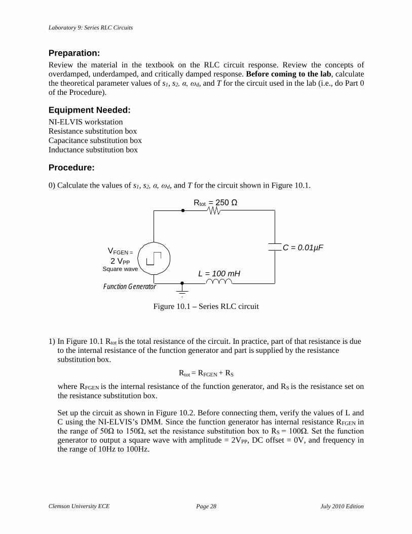
0) Calculate the values of s1, s2, α, ωd, and T for the circuit shown in Figure 10.1.
Rtot = 250 Ω
VFGEN =
2 VPP Square wave
Function Generator
L = 100 mH
C = 0.01µF
Figure 10.1 – Series RLC circuit
1) In Figure 10.1 Rtot is the total resistance of the circuit. In practice, part of that resistance is due to the internal resistance of the function generator and part is supplied by the resistance substitution box.
Rtot = RFGEN + RS
where RFGEN is the internal resistance of the function generator, and RS is the resistance set on the resistance substitution box.
Set up the circuit as shown in Figure 10.2. Before connecting them, verify the values of L and C using the NI-ELVIS’s DMM. Since the function generator has internal resistance RFGEN in the range of 50Ω to 150Ω, set the resistance substitution box to RS = 100Ω. Set the function generator to output a square wave with amplitude = 2VPP, DC offset = 0V, and frequency in the range of 10Hz to 100Hz.

Clemson University ECE
Page 29 July 2010 Edition
Laboratory 9: Series RLC Circuits
RFGEN
VFGEN =
2 VPP Square wave
L = 100 mH Function Generator
= V e .
RS = 100 Ω
C = 0.01µF
Figure 10.2 – Series RLC circuit to measure voltage on inductor
a) Connect CH 0 of the oscilloscope to display the voltage across the inductor. To avoid a grounding error, the inductor must have one lead connected to ground.
b) To get a stable image of the circuit oscillations, connect a lead from the FGEN output to CH1 of the oscilloscope. Then set the scope’s trigger to EDGE, CH 1, rising slope.
c) Adjust the period of the square wave, if necessary, so that the damped sinusoidal waveform decreases to a negligible value (i.e., dampens out) before the next square-wave pulse occurs. Something in the range of 10 Hz to 100 Hz probably will be adequate.
d) Draw an accurate representation of the transient sinusoidal waveform (the damped oscillations) in your laboratory notebook. If you have a USB flash drive, you can use the oscilloscope’s LOG button to download a log file of the waveform data for later analysis in a spreadsheet. To do so, you must first stop the acquisition by pressing STOP or by using the “RUN ONCE” mode.
2) Expand the time scale of the oscilloscope to show 3 to 6 peaks of the damped sinusoidal
oscillation. Using the CURSORS function of the oscilloscope, measure the period of the damped sinusoidal waveform. Compare this value to T obtained in Part 0.
3) Measure the peak height of the first full peak of the damped sinusoidal waveform and the peak
height at the next peak (+1 cycle). Measure the time difference Δt between these two peaks.
a) Determine the Neper frequency (damping coefficient), α, using your measurements and the equation
Vpeak 2 − ⋅∆t
peak1
b) Compare your measured α to the value you calculated in Part 0.
c) For your experimental α, calculate the total resistance Rtot in the circuit. (α = Rtot/2L)
d) Calculate the function generator’s internal resistance RFGEN = Rtot – RS.
4) Now knowing RFGEN, adjust RS so that Rtot = 250 Ω. Again measure the damping coefficient, α, and compare the new measured value to your calculated value from Part 0.

Clemson University ECE
Page 30 July 2010 Edition
Laboratory 9: Series RLC Circuits
RFGEN
VFGEN =
2 VPP Square wave C = 0.01µF
Function Generator
5) Swap the positions of the inductor and the capacitor, as shown in Figure 10.3.
RS = 100 Ω
L = 100 mH
Figure 10.3 – Series RLC circuit to measure voltage on capacitor
Connect CH0 of the oscilloscope to measure the voltage across the capacitor, being careful to avoid grounding errors. Continue to trigger the scope using the FGEN signal on CH1, as before. In your laboratory notebook, sketch the waveform of the voltage across the capacitor.
Notice that if you were to perform the calculation for α using these data, you would need to subtract from the peak heights the 1-volt offset provided by the pulse from the function generator. Doing so, you could again calculate α as in Part 3.
Critical damping: For the values of L and C used in this circuit, calculate the value of total series resistance Rtot that gives critical damping. Change the resistance RS so that Rtot equals this value. Again observe the voltage drop across the capacitor and sketch the resulting waveform in your laboratory notebook.
Overdamped: Change RS so that Rtot is 10 times the value you calculated for critical damping. Observe and record the capacitor voltage response.
Probing Further: 1) Describe the differences between the underdamped, overdamped, and critically damped
responses in the capacitor voltage, VC. What are the potential advantages or disadvantages of an electrical system behaving in each mode of operation? What is the functional form of the transient response (be specific) if the circuit is critically damped?
2) Explain why the inductor voltage, VL, is greater than the amplitude of the incoming square
wave at the time of a square wave transition (initial condition).
Report: Your Laboratory Teaching Assistant will inform you when a report is due, and on which experiment you will report. Make sure that you have recorded all necessary information and data in your laboratory notebook to enable you to prepare a report on this experiment, if so directed, at some time in the future.

Clemson University ECE
Page 31 July 2010 Edition
Laboratory 10: Statistical Analysis
Introduction:
Laboratory 10 Statistical Analysis
The student is already aware of some error introduced by assuming ideal meters in the measurement process. Another uncertainty lies in the use of the circuit components themselves. While a component is designed to have a particular value (its "nominal" value), which is marked on the outside covering (the "case" or "encapsulation"), random fluctuations in materials and production processes will result in some range of values for the manufactured devices. Thus, components are usually specified by a nominal value and a range, called the tolerance, in which the actual value is expected to lie. For example, resistors are specified as being within a stated tolerance of the given (nominal) value. This tolerance can be as small as 1% for "precision" resistors to as large as 20%. The tolerance may be indicated by a color band or by a percentage value printed on the body of the resistor. It is important to know how to identify the tolerance of the resistors used in a particular circuit and to understand what the specified nominal value and tolerance for a component means statistically.
Objective: By the end of this lab, the student should know how to apply statistical methods to obtain the best estimate of the true value of a circuit component.
Preparation: Read Appendix C, Fundamentals of Statistical Analysis. Become familiar with the concepts of mean, standard deviation, and variance and the formulas used for calculating these quantities.
Equipment Needed: NI-ELVIS II workstation.
Procedure:
0) The lab instructor will provide each team with a group of five resistors. Each group of resistors should be labeled GROUP A, GROUP B, GROUP C, etc. These will be passed in turn from lab team to lab team.
1) For each group of resistors, measure the resistance of each component using the NI-ELVIS
digital multimeter. Make a table for each group, recording the resistances. 2) For the resistors in each group, calculate the mean, the standard deviation, and the variance.
Make a table showing these values for each of the groups. When you make this table, include a row, labeled "TOTAL", and calculate the mean, standard deviation, and variance for all of the resistance values that you measured.

Clemson University ECE
Page 32 July 2010 Edition
Laboratory 10: Statistical Analysis
3) Make another table with rows labeled "TEAM 1", "TEAM 2", etc. and record the values of mean, standard deviation, and variance for each resistor group and for the total determined by other lab teams in Part 2. Why do the values differ?
4) Using the information in Parts 2 and 3, what would be the best estimate of the resistance of
each group? What would be the best estimate of the resistance for all groups of resistors combined? Why?
Probing Further:
1) Is it reasonable to assume the resistors have a normal distribution? Why? 2) How does the mean value of resistance for the total, obtained by your lab team, compare to the
nominal value of resistance marked on the resistor’s body? 3) How does the standard deviation obtained by your team compare to the tolerance marked on
the resistor case?
Report: Your Laboratory Teaching Assistant will inform you when a report is due, and on which experiment you will report. Make sure that you have recorded all necessary information and data in your laboratory notebook to enable you to prepare a report on this experiment, if so directed, at some time in the future.

Clemson University ECE
Page 33 July 2010 Edition
Laboratory 11: Design Lab
Introduction:
Laboratory 11 Design Lab
In this lab you will design and build a circuit to meet certain criteria. In calling for a circuit design, two fundamental questions must be answered: 1) "What function is the circuit to perform?", and 2) "How well is the circuit expected to perform this function?". The detailed answers to these questions are usually called the functional requirement and the specifications, respectively.
Objective: The objective of this laboratory exercise is to introduce you to the nature of the engineering design process, i.e., the process of selecting combinations of components to perform a given function with a given degree of precision.
Preparation: Review the material in your circuits textbook on voltage dividers. Before you come to lab, you should have your circuit design completed, with the design procedure and the resulting circuit recorded in your laboratory notebook. This is not a team exercise. Each individual will be required to have a design completed in the notebook prior to coming to lab class.
Equipment Needed:
? (you specify).
Procedure:
1) You are to design a voltage regulator circuit that will provide 7.00V across a load resistance, RL, which may vary anywhere between 1000Ω and 1500Ω. The supply voltage source is to be 10.00V. You are to use resistors R1 and R2 between the 10V source and RL in a voltage divider network. You must select the values of these resistors to obtain no more than a +5% variation about 7.00V as the value of RL ranges from 1000Ω to 1500Ω. Initially, you can assume that the selected values of resistances R1 and R2 are precise (i.e. 0% tolerance). In your laboratory notebook show your design procedure and your calculations to determine values of R1 and R2.
2) After discussing the circuit design with the lab instructor, connect the circuit and test it. When you have met the specifications, demonstrate the performance of your regulator circuit to your LTA.
3) Suppose that the specifications had included the additional requirement that the voltage
divider was to dissipate the minimum possible power while meeting the 7.00V ± 5% specification. How would this have changed your design?
Clemson University ECE
Page 34 July 2010 Edition
Laboratory 11: Design Lab
Probing Further:
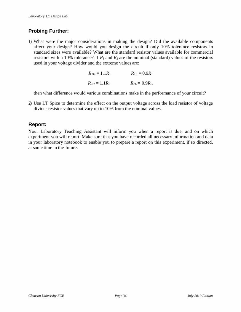
1) What were the major considerations in making the design? Did the available components affect your design? How would you design the circuit if only 10% tolerance resistors in standard sizes were available? What are the standard resistor values available for commercial resistors with a 10% tolerance? If R1 and R2 are the nominal (standard) values of the resistors used in your voltage divider and the extreme values are:
R1H = 1.1R1 R1L = 0.9R1
R2H = 1.1R2 R2L = 0.9R2,
then what difference would various combinations make in the performance of your circuit? 2) Use LT Spice to determine the effect on the output voltage across the load resistor of voltage
divider resistor values that vary up to 10% from the nominal values.
Report: Your Laboratory Teaching Assistant will inform you when a report is due, and on which experiment you will report. Make sure that you have recorded all necessary information and data in your laboratory notebook to enable you to prepare a report on this experiment, if so directed, at some time in the future.

Clemson University ECE
Page 35 July 2010 Edition
Laboratory 12: Final Exam
Introduction:
Laboratory 12 Final Exam
This has been your first engineering laboratory. Although you have been provided with a "cookbook" (this manual), hopefully you have not just blindly followed instructions in order to get a good grade. If you have, you have cheated only yourself. The theory which you have learned from your textbook and lectures is a way of looking at reality and thinking about how to organize experience, i.e., dealing with real, physical things. It is only through combining practical experience with theory that you can begin to develop the necessary analytical skills to aid you in "taking things apart and putting them together in new ways" that is the essence of the practice of real engineering.
Objective: This examination is designed to help you and your LTA determine how much you have developed your knowledge, skills, and self confidence.
Preparation: Review your lab manual. Think carefully of the procedures which you have followed and what you have learned from them. How do you measure voltage, current, resistance, frequency, etc.? How accurate are your measurements? When your measurements do not agree with those of your peers, what is the cause? How do your measuring instruments affect the circuit in which you are trying to make measurements?
Equipment Needed: Pencil Calculator
Procedure: 1) The final exam will consist of a written exam and a practical exam. The practical exam involves performing a lab procedure to obtain a desired result. The written exam will cover the application of theory to understand circuit behavior, based upon your laboratory experiences in this course.
Probing Further: 1) This has been your first in a series of four (4) laboratory courses. What have you done to develop your expertise and skills? What will you do differently in the next course? What have you learned from your experience?
Report: No report is due for this experiment. Laboratory notebooks are to be turned in to the LTA for evaluation.

Clemson University ECE
Page 36 July 2010 Edition
Part III Appendices

Clemson University ECE
Page 37 July 2010 Edition
Appendix A: Safety
Appendix A: Safety
Electricity, when improperly used, is very dangerous to people and to equipment. This is especially true in an industrial environment where large amounts of power are used, and where high voltages are present [A-1]; in environments where people are especially susceptible to electric shock such as maintenance of a high voltage system (while in operation) or in hospitals where electrical equipment is used to test or control physiological functions [Α-2, Α-3]; and in an experimental or teaching laboratory where inexperienced personnel may use electrical equipment in experimental or nonstandard configuration.
Engineers play a vital role in eliminating or alleviating the danger in all three types of environments mentioned above. For conditions where standard equipment is used in standard configurations, governmental agencies and insurance underwriters impose strict laws and regulations on the operation and use of electrical equipment including switchgear, power lines, safety devices, etc. As a result, corporations and other organizations in turn impose strict rules and methods of operation on their employees and contractors. Engineers who are involved in using electrical equipment, in supervising others who use it, and in designing such systems, have a great responsibility to learn safety rules and practices, to observe them, and to see that a safe environment is maintained for those they supervise. In any working environment there is always pressure to "get the job done" and take short cuts. The engineer, as one who is capable of recognizing hazardous conditions, is in a responsible position both as an engineer and as a supervisor or manager and must maintain conditions to protect personnel and avoid damage to equipment.
Because of their non-standard activities, experimental laboratories are exempt from many of these rules and regulations. This puts more responsibility on the engineer in this environment to know and enforce the safest working procedures.
The knowledge and habit-forming experience to work safely around electrical equipment and the ability to design safe electrical equipment begins with the first student laboratory experience and continues through life. This includes learning the types of electrical injuries and damage, how they can be prevented, the physiology of electrical injuries, and steps to take when accidents occur.
Physiology of Electrical Injuries:
There are three main types of electrical injuries: electrical shock, electrical burns, and falls caused by electrical shock. A fourth type, 'sunburned' eyes from looking at electric arcs, such as arc-welding, is very painful and may cause loss of work time but is usually of a temporary nature. Other injuries may be indirectly caused by electrical accidents, e.g., burns from exploding oil-immersed switch gear or transformers.
Although electric shock is normally associated with high-voltage AC contact, under some circumstances death can occur from voltages from substantially less than the nominal 120 Volts

Clemson University ECE
Page 38 July 2010 Edition
Appendix A: Safety
AC found in residential systems. Electric shock is caused by an electric current passing through a part of the human body. The human body normally has a high resistance to electric currents so that a high voltage is usually required to cause lethal currents. This resistance is almost all in the skin, but when the skin is wet its resistance is much lower. When a person is hot and sweaty or is standing in water, contact with 120 Volts or less is likely to cause a fatal shock.
Electric shock is not a single phenomenon but is a disturbance of the nerves that is caused by electric current. A current through a part of the body such as the arm or leg will cause pain and muscle contraction. If a victim receives an electric shock from grasping a live conductor, a current of greater than 15 to 30mA through the arm will cause muscle contractions so severe that the victim cannot let go. Similar currents through leg muscles may cause sudden contractions causing the victim to jump or fall, resulting in possible injuries or death. It is also possible for a prolonged period of contact of more than a minute or so to cause chest muscles to be contracted, preventing breathing and resulting in suffocation or brain damage from lack of oxygen.
The predominant cause of death by electric shock is generally attributed to ventricular fibrillation, which is an uncontrolled twitching or beating of the heart that produces no pumping action and therefore no blood circulation. Unless corrective action is taken, death follows quickly from lack of oxygen to the brain. While the amount of current that will cause fibrillation depends on several variables, 0.5 to 5A through the body will normally cause the very small current through the heart that causes fibrillation in most people. Larger currents than this through the heart causes contraction or clamping of the heart muscle and resulting death unless corrective action is taken.
Burns from electric currents may be caused by electric currents flowing in or near parts of the body. Such burns, if caused by high frequency sources, are deeper than burns from other sources and take longer to heal but otherwise are not different from normal heat burns.
Source of Electric Shock:
Since electric shock is caused by an electric current through a part of the body, it is prevented by not allowing the body to become part of any electric circuit. From this viewpoint, electric circuits may be classified as either grounded or ungrounded.
Grounded circuits are safer for most conditions, since they result in known voltages at other points in the circuit and provide easier and better protection against faulty conditions in the circuit. The disadvantage is that a person standing on a non-insulated floor can receive a shock by touching only one conductor.
Almost all electric power generation, transmission, and distribution systems are grounded to protect people and equipment against fall conditions caused by windstorms, lightning, etc. Residential, commercial, and industrial systems such as lighting and heating are always grounded for greater safety. Communication, computer, and similar systems are grounded for safety reasons and to prevent or reduce noise, crosstalk, static, etc. Many electronic equipments or instruments are grounded for safety and noise prevention, also. Common examples are DC power supplies, oscilloscopes, oscillators, and analog and digital multimeters.

Clemson University ECE
Page 39 July 2010 Edition
Appendix A: Safety
Ungrounded circuits are used in systems where isolation from other systems is necessary, where low voltages and low power are used, and in other instances where obtaining a ground connection is difficult or impractical. In the ungrounded circuit, contact with two points in the circuit that are at different potentials is required to produce an electrical shock. The difficulty is that with no known ground, a hidden fault can occur, causing some unknown point to be grounded. Thus, touching a supposedly safe conductor while standing on the ground would result in an electric shock.
Prevention of Shock in the Laboratory:
Prevention of electric shock to individuals and damage to equipment in the laboratory can be done by strict adherence to several common-sense rules summarized below:
1) When hooking up a circuit, connect to the power source last, while power is off.
2) Before making changes in a circuit, turn off or disconnect the power first, if possible.
3) Never work alone where the potential of electric shock exists.
4) When changing an energized connection, use only one hand. Never touch two points in the
circuit that are at different potentials.
5) Know that the circuit and connections are correct before applying power to the circuit.
6) Avoid touching capacitors that may have a residual charge. The stored energy can cause a severe shock even after a long period of time.
7) Insulate yourself from ground by standing on an insulating mat where available.
After Accident Action:
Since accidents do happen despite all efforts to prevent them, plans for appropriate reaction to an accident can save time and lives. Such a plan should include immediate availability of first aid material suitable for minor injuries or for injuries that are likely because of the nature of the work. Knowledge of how to obtain trained assistance such as Emergency Medical Services (EMS) should be readily available for everyone.
Treating victims for electrical shock includes four basic steps that should be taken immediately. Step two requires qualification in CPR and step three requires knowledge of mouth-to-mouth resuscitation. Everyone who works around voltages that can cause dangerous electrical shock should take advantage of the many opportunities available to become qualified in CPR and artificial respiration.
Immediate Steps After Electric Shock:
1) Shut off all power and remove victim from the electric circuit. If the power cannot be shut off immediately, use an insulator of some sort, such as a wooden pole, to remove victim from
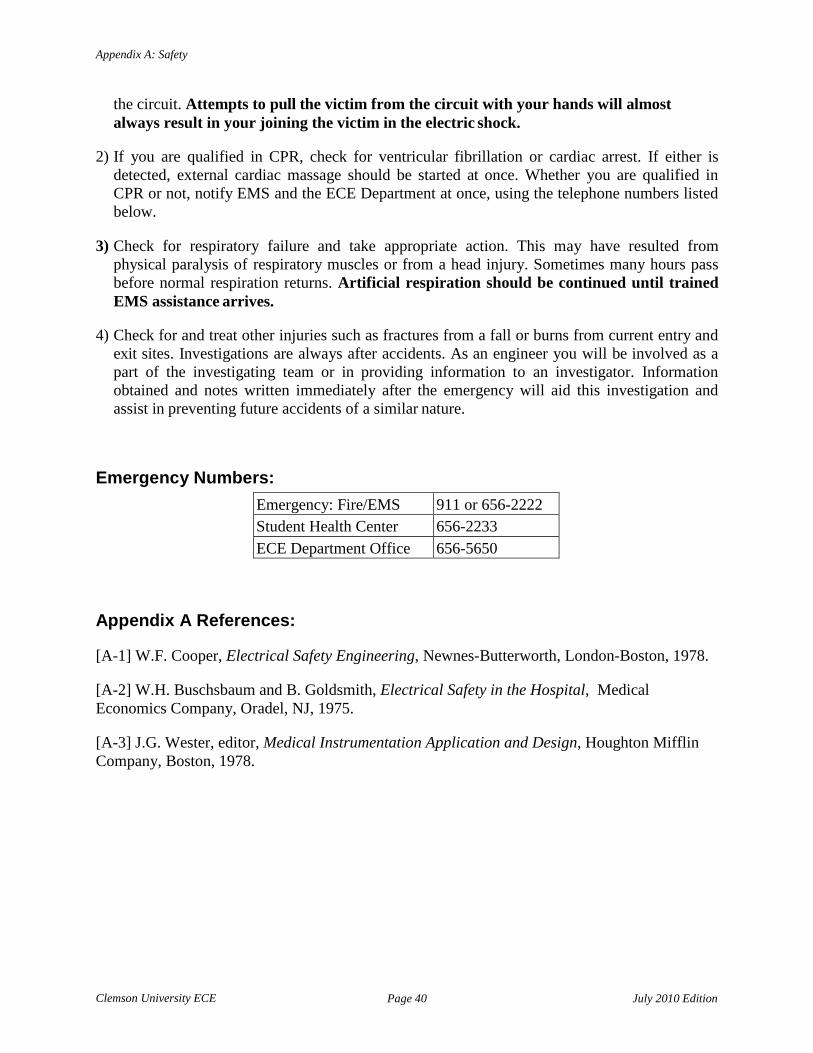
Clemson University ECE
Page 40 July 2010 Edition
Appendix A: Safety
the circuit. Attempts to pull the victim from the circuit with your hands will almost always result in your joining the victim in the electric shock.
2) If you are qualified in CPR, check for ventricular fibrillation or cardiac arrest. If either is
detected, external cardiac massage should be started at once. Whether you are qualified in CPR or not, notify EMS and the ECE Department at once, using the telephone numbers listed below.
3) Check for respiratory failure and take appropriate action. This may have resulted from
physical paralysis of respiratory muscles or from a head injury. Sometimes many hours pass before normal respiration returns. Artificial respiration should be continued until trained EMS assistance arrives.
4) Check for and treat other injuries such as fractures from a fall or burns from current entry and
exit sites. Investigations are always after accidents. As an engineer you will be involved as a part of the investigating team or in providing information to an investigator. Information obtained and notes written immediately after the emergency will aid this investigation and assist in preventing future accidents of a similar nature.
Emergency Numbers:
Emergency: Fire/EMS 911 or 656-2222 Student Health Center 656-2233 ECE Department Office 656-5650
Appendix A References:
[A-1] W.F. Cooper, Electrical Safety Engineering, Newnes-Butterworth, London-Boston, 1978. [A-2] W.H. Buschsbaum and B. Goldsmith, Electrical Safety in the Hospital, Medical Economics Company, Oradel, NJ, 1975.
[A-3] J.G. Wester, editor, Medical Instrumentation Application and Design, Houghton Mifflin Company, Boston, 1978.

Clemson University ECE
Page 41 July 2010 Edition
Appendix B: Fundamentals of Electrical Measurements
Appendix B: Fundamentals of Electrical Measurements
Electrical engineers make and use a wide variety of measurements of electrical circuit variables, such as voltage, current, frequency, power, and energy, as well as of electrical circuit parameters such as resistance, capacitance, and inductance. Even though many instruments which can be used to make such measurements are commercially available, the proper use and interpretation of these measurements depend on a fundamental understanding of how these measuring instruments work, their capabilities, and their limitations.
This appendix provides a brief overview of the fundamentals of electrical measurements. There are many textbooks on the subject. See References [B-1] through [B-6] of this appendix, for example. As your exposure to various types of electrical measuring instruments increases in this and subsequent laboratory courses, you will find some of these books, or similar books that you can find, useful in developing your understanding and measurement skills. In addition, many commercial instrument manufacturers publish handbooks and applications notes that provide more information on specific measurement techniques.
Measurement of Current and Voltage:
The basic electrical circuit variables of current and voltage are measured with ammeters (for current) and voltmeters (for voltage). These instruments may use either analog (or continuous) or digital (or numerical) indicators (or "readouts").
Analog Meter Instruments
The analog instruments were those developed early in the history of electrical science and technology. Most are based on the d'Arsonval galvanometer movement. A brief description of this meter movement and its use in ammeters and voltmeters is given in the textbook ELECTRIC CIRCUITS, Fifth Edition by J.W. Nilsson [B-7]. More information is available in References [B- 1] and [B-2]. In the d'Arsonval galvanometer, current through a coil of fine wire develops a magnetic field which opposes that of a permanent magnet to rotate a needle across a scale which is calibrated (marked off) in units of the measured variable.
Current Measurement:
The basic meter movement can be modeled as a resistance, RM, which represents the resistance of the fine wire coil, in series with an ideal (zero resistance) meter movement, M, as shown in Figure B.1. The important parameters for this meter are the full-scale current, IMFS, and RM. The full-scale current is the value of current that rotates the indicating needle through its maximum arc. Note that a larger current may damage the meter movement permanently, rendering it useless.

Clemson University ECE
Page 42 July 2010 Edition
Appendix B: Fundamentals of Electrical Measurements
Rsh
Figure B.1 - Electrical circuit model for d'Arsonval meter movement.
The voltage drop across the meter movement will be
VM = IRM (B-1)
and the maximum rated voltage drop for the meter will be
VMFS = IMFSRM. (Β-2)
When it is necessary to measure currents larger than IMFS, a resistor with a value of resistance, Rsh, smaller than that of the meter, RM, is placed in parallel with the meter movement. The parallel resistor is usually called the shunt resistor. Figure Β.2 shows a circuit diagram for this arrangement.
Figure B.2 - Electrical circuit model for d’Arsonval meter movement with a shunt resistance.
From Figure Β.2, it is obvious that I = I + I
= VM + VM
(B-3)
M sh
RM Rsh
and that the full scale current IFS for this metering arrangement will be

Clemson University ECE
Page 43 July 2010 Edition
Appendix B: Fundamentals of Electrical Measurements
I = I R 1+ M
(B-4) FS MFS R
sh
Below, in Figure Β.3 is the circuit diagram symbol for an ammeter compared to the equivalent circuit model for the analog ammeter which uses a d'Arsonval galvanometer.
Figure Β.3 - Electrical circuit model for ammeter using a d'Arsonval meter movement with a shunt resistance and the circuit diagram symbol for the ammeter.
Example B-1: Consider a d'Arsonval meter movement with the following characteristics:
IMFS = 50μΑ RΜ = 5kΩ
VMFS = 250mV. Find the value of shunt resistance that will enable the measurement of up to 1mA of current.
⇒ From Equation Β-4,
1+ RM
Rsh
or
= IFS
IMFS = 1mA
50µA = 20
R = RM = 5000 Ω = 263.16 Ω
sh 19 19
Exercise B-1: What value of Rsh is required to make a meter that would measure 100mA full scale?
Rsh

Clemson University ECE
Page 44 July 2010 Edition
Appendix B: Fundamentals of Electrical Measurements
Voltage Measurement: A d'Arsonval galvanometer movement can also be used to make a voltmeter. Instead of placing a resistor in shunt, a resistor is placed is series with the meter movement. Figure B.4 shows the equivalent circuit for such an arrangement, connected in series with a voltage source, VX, which has an internal resistance, RX, associated with it. Also shown is the circuit symbol used to indicate the presence of such a voltmeter in a circuit.
Figure B.4 - Equivalent circuit for voltmeter circuit using d’Arsonval galvanometer with series resistance and the circuit symbol used for a voltmeter.
The maximum voltage, VFS, that can be applied will depend upon the size of the series resistor, RS. By applying Kirchhoff's voltage law to the circuit of Figure B.4 we have
VFS = IMFS (RS + RM + RX ). (B-5)
Example B-2: Using the meter movement previously used, suppose that it is desired to make a voltmeter with a 100V full-scale rating. From Equation (B-5)

Clemson University ECE
Page 45 July 2010 Edition
Appendix B: Fundamentals of Electrical Measurements
R = VFS − R
− R ,
and
S
RS =
IMFS
100 50 ⋅10−6
M X
− 5000 − RX ,
RS = 1.995 MΩ – RX.
Often RX is not precisely known, or is inconvenient to determine. If RX is small enough compared to RS to be considered negligible, it will have a small effect on the accuracy of the voltage measurement. If not, the "loading effect" of the voltmeter on the voltage source must be taken into account. A procedure for doing this will be used in Laboratory Experiment Number 2.
Exercise B-2: Assuming that RX is small, say 100Ω, what value of RS would be required to make a voltmeter with 10V full scale rating using the same meter movement as in the example above?
Analog Electronic Instruments
From the circuit diagram of Figure B.4 it can be seen that if the unknown voltage source, VX, has an internal resistance associated with it that approaches or exceeds that of the voltmeter circuit, the reading will be in error due to the voltage drop across the internal resistance of the source. The analog electronic instruments were developed to provide a high input impedance for the voltmeter in order to minimize such a "loading effect" of the measuring instrument on the circuit being measured.
The early versions of such electronic voltmeters used vacuum tube amplifiers and were consequently known as "vacuum tube voltmeters" or VTVMs. More recent instruments use the high impedance offered by field-effect transistors in operational amplifiers (FET-input op-amps). The output voltage of the op-amp can then be used to drive a d’Arsonval galvanometer to provide a continuous (analog) indication. However, the advent of digital circuits and indicating devices has enabled the development of digital meters, which will be briefly reviewed in the next section.
Digital Instruments
Figure Β.5 shows a block diagram of an electronic ammeter with a digital readout. Figure Β.6 shows a block diagram of an electronic voltmeter with a digital readout. Except for the input circuitry, both instruments are similar in design and construction.

Clemson University ECE
Page 46 July 2010 Edition
Appendix B: Fundamentals of Electrical Measurements
Figure Β.5 - Block diagram of electronic ammeter with a digital display readout.
Figure Β.6 - Block diagram of electronic voltmeter with a digital display readout. The input module of the digital electronic ammeter in Figure Β.5 and that of the digital electronic voltmeter in Figure Β.6 is usually built around an operational amplifier and other transistor devices. You will learn more about these in ECE 320 and ECE 321. The A/D (spoken as "A to D") converter and other digital circuit devices you will learn more about in ECE 371.
The input resistance of the digital electronic ammeter is designed to be as low as possible (ideally zero), whereas the input resistance of the digital electronic voltmeter is designed to be as high as possible (ideally infinite).
How Good Are Your Measurements?
In engineering practice, although qualitative words like "good" and "bad" are used, more often than not quantitative descriptions are used, i.e. how good or bad, in numerical terms. When making measurements, three attributes are of interest: accuracy, precision, and resolution.
Accuracy is usually expressed as a percentage, and represents the difference, in percent, of the readout value of the measuring instrument compared to the actual, or true, value. Usually the accuracy specification of an instrument is expressed as a percentage of the full-scale value on a given range. For example, if you are using a voltmeter with an accuracy of 2% of full scale on the 0-10V range and you obtain a scale reading of 4.8V, you would expect the actual voltage to be within the range of 4.8 ± 0.2V.
For digital display instruments, the accuracy specification is usually given as a percentage of full scale on the range being used plus one digit (the lowest-order digit). Thus, for example, if a digital voltmeter with 4 digits is being used on the 0–20V range and the accuracy specification is ± (0.1% + 1 digit), a reading of 13.42V will indicate an actual input voltage in the range 13.42 ± 0.03V.
Precision is used to indicate how closely the readout can be read. For example, an ammeter using a d'Arsonval meter movement for readout with a scale calibrated in units of 0.2 of each major subdivision can provide an estimate down to about 0.1 of a major subdivision. That is, an ammeter with a scale subdivided into 10 major subdivisions (0.1 mA per major subdivision) with these major subdivisions further partitioned into 5 minor subdivisions (of 0.02 mA each) might

Clemson University ECE
Page 47 July 2010 Edition
Appendix B: Fundamentals of Electrical Measurements
allow and estimate of 0.01 mA (or 10 μΑ) if the indicating needle is backed with a mirror that allows the observer to carefully align the needle with the scale.
For a digital readout, the precision is determined by the number of digits available in the display. For example, a readout that has 4 digits on a voltmeter being used on the 0-20V range would have a precision of 0.01V and on the 0-200V range would have a precision of 0.1V. Note that the precision of an instrument will usually be better than its accuracy.
Resolution is used to indicate the smallest change of the input variable to which the instrument (sensibly, through its readout) can respond.
Just because the original specifications for a given instrument state a given accuracy doesn't mean that the instrument is guaranteed to retain that accuracy indefinitely. Measuring instruments, like all manufactured items, are subject to "wear and tear". An instrument which is being used within its ratings – i.e. hasn't been abused electrically or mechanically (like being dropped on a workbench or onto the floor) – still requires periodic maintenance and recalibration. The procedure for re-calibration is usually specified in the instruction manual for the instrument, provided by the manufacturer. It is the usual (good) practice for the person performing the recalibration to place a "sticker" on the outside of the instrument giving the date of servicing and the name (or initials) of the person responsible. In industrial plants, where accurate measurements are important, the calibration procedures are usually performed in an instrument shop which is equipped with "secondary standards" of voltage, current, resistance, etc. traceable to the National Institute of Standards and Technology (NIST – formerly known as NBS, the National Bureau of Standards).
When using an instrument, refer to the instruction manual for correct usage and for specifications on the accuracy and resolution of the instrument. Also check to see what the last date of calibration was. The longer the interval between calibration and your date of using the instrument, the more suspect is the accuracy of your measurements. It is good practice to have a "known" voltage source (such as a "fresh" 1.5V battery) to quickly check a voltmeter or current source (such as a 1.5V battery in series with a 1.5 kΩ resistor to provide 1 mA) to obtain a quick check of an ammeter. If several instruments are available, they can be used with the same source to obtain a comparison of readings. The best rule of measurement is "check it out before you believe the readings".
How Good Are Their Measurements Compared To Mine?
Often the measurements made by two engineers, or two different groups of engineers, under ostensibly similar conditions, using ostensibly similar sets of instruments and equipment will result in different values, sometimes what appear to be significantly different value. The consequences may range from a "friendly dispute" to lawsuits.
Various engineering organizations, such as the American Society for Testing Materials (ASTM), go to great lengths to standardize measurement procedures and then to compare the results obtained by various people in different organizations using these procedures. One method of doing this is the so-called "round-robin" method.

Clemson University ECE
Page 48 July 2010 Edition
Appendix B: Fundamentals of Electrical Measurements
In the "round-robin" method, a set of objects to be measured – for example, a set of standard voltage cells – will be sent from laboratory to laboratory for measurements to be made. Then each group making the measurements will report them to a central group, the referee, for comparison. Following a statistical analysis of the individual and pooled measurements, the results are reported back to all of the participants. This method helps to establish the practical limits on repeatability of the measurements made using the procedure.
In general, there are many types of errors that can interfere with an accurate measurement of a variable such as a voltage value. These can be partitioned [B-1, B-2] into three categories: human errors, systematic errors, and random errors.
Human errors are caused by a loss of concentration, ignorance, or laziness on the part of the human being making and/or recording the measurement(s). Such errors include: choosing the wrong scale or even instrument, misreading the scale, transposing numbers when recording, etc. For this reason, it is helpful to have one or more lab partners observing or repeating the measurements in order to catch such errors before they become a problem.
Systematic errors may be due to equipment (instrument) errors or to environmental conditions. An example of the instrument error is the use of an instrument that is out of calibration, or one for which the zero has not been properly adjusted. Many instruments are temperature sensitive, and will give erroneous readings when used out of their specified ambient temperature range. They may also be sensitive to the presence of large magnetic fields or sensitive to high humidity. In some cases, the effects of environmental conditions may be accounted for if known, but quite often either an accurate measurement of actual instrument temperature or its local humidity are not known, so correction is not possible.
Random errors are those errors which are due to unknown causes and which are operative when the human errors and the systematic errors have been brought under control or otherwise accounted for. These random errors can be minimized or accounted for by the use of multiple measurements and statistical analysis. Statistical analysis terminology and methodology are discussed in Appendix C of this manual.
Appendix B References:
[B-1] F. Spitzer and B. Howard, Principles of Modern Instrumentation. New York: Holt, Rinehart and Winston, 1972.
[B-2] T.L. Zapf. "Accuracy and Precision". pp 4-1 through 4-20 in C.F. Coombs, Jr. (ed.). Basic Electronic Instrument Handbook. New York, NY: McGraw-Hill. 1972.
[B-3] S. Wolf. Guide to Electronic Instrument and Laboratory Practice. Englewood Cliffs, NJ: Prentice-Hall. 1973.
[B-4] H.V. Malmstadt, C.G. Enke, S.R. Crouch, and G. Horlick. Electronic Measurement for Scientists. Menlo Park, CA: W.A. Benjamin, Inc. 1974.
[B-5] H.H. Chiang. Electrical and Electronic Instrumentation. New York, NY: John Wiley and Sons. 1984.

Clemson University ECE
Page 49 July 2010 Edition
Appendix B: Fundamentals of Electrical Measurements
[B-6] F.F. Mazda. Electronic Instruments and Measurement Techniques. Cambridge (U.K.): Cambridge University Press, 1987.
[B-7] J.W. Nilsson. Electric Circuits, Fifth Edition. Reading, MΑ: Addison-Wesley, 1996.

Clemson University ECE
Page 50 July 2010 Edition
Appendix C: Fundamentals of Statistical Analysis
Appendix C: Fundamentals of Statistical Analysis
When the human errors and systematic errors associated with a measurement procedure have been eliminated or brought under control, there will still be some variability in the measurements when they are repeated, or when some other person, presumably equally skilled, makes the measurement. These are called random errors. They are characterized by irregularity, which may appear to be a source of potential disagreement or confusion. However, the use of statistical analysis methods makes possible the extraction of essential information. Two characteristics of the measurements are of special interest: the average (arithmetic mean) value of a series of measurements and some measure of the spread, or dispersion, i.e., the degree of variability about the mean.
Consider a series of measurements: x1, x2, x3, ..., xn of some quantity. For example, 6 measurements of a voltage source over a period of an hour, repeated for 5 consecutive hours. Table C-1 provides values for each of these measurements.
Measurement Νο. Hour 1 Hour 2 Hour 3 Hour 4 Hour 5
1 5.043 5.048 5.040 5.044 5.047 2 5.038 5.043 5.044 5.044 5.041 3 5.036 5.046 5.042 5.039 5.040 4 5.035 5.042 5.039 5.036 5.042 5 5.040 5.040 5.043 5.045 5.037 6 5.043 5.038 5.041 5.400 5.039
Table C.1 - Voltage measurements of a source over a 5-hour interval. For each sample of n measurements one can calculate an average or arithmetic mean value from
(C-1) and a variance
(C-2) More often, the square root of the variance, called the standard deviation, s, is used rather than the variance. As can be seen from Equation (C-2), the variance is the mean-square deviation of each measurement from the average value. Therefore, the standard deviation is the root-mean- square deviation of the set of measurements.

Clemson University ECE
Page 51 July 2010 Edition
Appendix C: Fundamentals of Statistical Analysis
Equations (C-1) and (C-2) have been used to calculate the average voltage, variance, and standard deviation for each of the sets of voltage measurements in Table C-1. The results are shown in Table C-2.
Parameter Hour 1 Hour 2 Hour 3 Hour 4 Hour 5
Vav 5.039 5.043 5.042 5.041 5.041
s2 1.18•10-5 1.38•10-5
0.35•10-5 1.27•10-5
1.16•10-5
s 0.0034 0.0037 0.0019 0.0036 0.0034 All Hours
(Vαν)αν 5.041
(s)αν 0.0015
Table C.2 – Statistics for voltage measurements of a source over a 5-hour interval. Also calculated and shown in Table C-2 is the average of the sample averages and the standard deviation of these averages. It can be seen that the sample averages are more tightly grouped about the average of the averages (or the "grand mean") than are the individual measurements grouped about their respective sample mean values.
Why would one go through such calculations? What is the interpretation of the results? From the original data tabulations in Table C-1 it can be seen that the maximum voltage measured was 5.047V and the minimum was 5.035V. This corresponds to a difference of 12mV, which compared to the grand mean value of 5.041V is only 0.24% for the range (Max-Min) and only ±0.12% about the grand mean. On a percentage basis, these results look very good. However, there are situations when the ability to resolve a few millivolts might be important, so it is important to characterize the ability of the voltmeter to make precise measurements. Another item of interest is to estimate how much of a deviation might be expected over a longer period of time.
Again looking at Table C-1, it can be seen that over any of the one hour periods the readings fluctuated up and down around the grand mean value. Only twice in a 5-hour period was the grand mean value obtained (2 out of 30 readings). This wandering back and forth is characteristic of the variation expected from the random interplay of various, uncontrolled, physical factors. The average value of a measurement might be thought about as "information" and the random fluctuations as "noise" that interferes (in this case rather slightly) with the process of obtaining the information.
We only took 5 samples (one per hour) of 6 readings each. What would we expect from, say, 20 readings per hour taken over the period of a month? Or perhaps, through automation, 1200 readings per hour, taken over a month. What information would we gain by greatly increasing the number of observations, and of course, greatly increasing the work of analyzing the data? In other words, how good are our inferences made from a few samples about the "true" values of mean and variance (or standard deviation)?

Clemson University ECE
Page 52 July 2010 Edition
Appendix C: Fundamentals of Statistical Analysis
The theory of measurement errors and their determination is based on the following observations [C-1]:
1) The most probable value that can be assigned to a measured magnitude, on the basis
of equally trustworthy direct measurements, is the arithmetic mean.
2) In any large number of measurements positive and negative errors of the same magnitude are equally likely to occur.
3) Small errors are much more likely to occur than large ones.
4) All of the errors of measurement in a given series lie between equal positive and
negative limits. These observations have led to the use of the normal distribution function to model the expected error distribution of a large (approaching infinity) series of measurements of the same kind. This large (infinite) reference group is called the population. The average value of the population (of measurements) is given the symbol μ. Its variance is symbolized as σ2 and its standard deviation is σ. In terms of these parameters, the normal distribution function is
Figure C.1 shows a plot of this distribution function in terms of a normalized variable.
or
to give a "universal curve". A related curve is that of the integral of (C-5), or
(C-3)
(C-4) (C-5)
(C-6)

Clemson University ECE
Page 53 July 2010 Edition
Appendix C: Fundamentals of Statistical Analysis
Figure C.1 - Normal distribution function versus z.
Figure C.2 – Cumulative normal distribution function versus z.
The integral in (C-6) is known as the cumulative normal distribution function. Values of this integral for positive values of z (i.e. for x > μ) are given in Table C.3. Values of the integral for z < 0 (i.e. for x < μ) are obtained from the relation
P(-z) = 1 – P(z). (C-7)
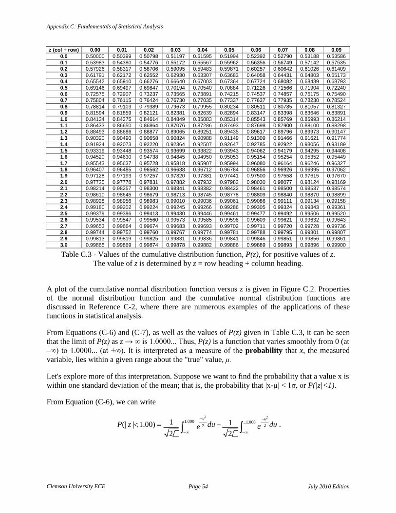
Clemson University ECE
Page 54 July 2010 Edition
Appendix C: Fundamentals of Statistical Analysis
2 ∫ 1.000 1 −
z (col + row) 0.00 0.01 0.02 0.03 0.04 0.05 0.06 0.07 0.08 0.09 0.0 0.50000 0.50399 0.50798 0.51197 0.51595 0.51994 0.52392 0.52790 0.53188 0.53586 0.1 0.53983 0.54380 0.54776 0.55172 0.55567 0.55962 0.56356 0.56749 0.57142 0.57535 0.2 0.57926 0.58317 0.58706 0.59095 0.59483 0.59871 0.60257 0.60642 0.61026 0.61409 0.3 0.61791 0.62172 0.62552 0.62930 0.63307 0.63683 0.64058 0.64431 0.64803 0.65173 0.4 0.65542 0.65910 0.66276 0.66640 0.67003 0.67364 0.67724 0.68082 0.68439 0.68793 0.5 0.69146 0.69497 0.69847 0.70194 0.70540 0.70884 0.71226 0.71566 0.71904 0.72240 0.6 0.72575 0.72907 0.73237 0.73565 0.73891 0.74215 0.74537 0.74857 0.75175 0.75490 0.7 0.75804 0.76115 0.76424 0.76730 0.77035 0.77337 0.77637 0.77935 0.78230 0.78524 0.8 0.78814 0.79103 0.79389 0.79673 0.79955 0.80234 0.80511 0.80785 0.81057 0.81327 0.9 0.81594 0.81859 0.82121 0.82381 0.82639 0.82894 0.83147 0.83398 0.83646 0.83891 1.0 0.84134 0.84375 0.84614 0.84849 0.85083 0.85314 0.85543 0.85769 0.85993 0.86214 1.1 0.86433 0.86650 0.86864 0.87076 0.87286 0.87493 0.87698 0.87900 0.88100 0.88298 1.2 0.88493 0.88686 0.88877 0.89065 0.89251 0.89435 0.89617 0.89796 0.89973 0.90147 1.3 0.90320 0.90490 0.90658 0.90824 0.90988 0.91149 0.91309 0.91466 0.91621 0.91774 1.4 0.91924 0.92073 0.92220 0.92364 0.92507 0.92647 0.92785 0.92922 0.93056 0.93189 1.5 0.93319 0.93448 0.93574 0.93699 0.93822 0.93943 0.94062 0.94179 0.94295 0.94408 1.6 0.94520 0.94630 0.94738 0.94845 0.94950 0.95053 0.95154 0.95254 0.95352 0.95449 1.7 0.95543 0.95637 0.95728 0.95818 0.95907 0.95994 0.96080 0.96164 0.96246 0.96327 1.8 0.96407 0.96485 0.96562 0.96638 0.96712 0.96784 0.96856 0.96926 0.96995 0.97062 1.9 0.97128 0.97193 0.97257 0.97320 0.97381 0.97441 0.97500 0.97558 0.97615 0.97670 2.0 0.97725 0.97778 0.97831 0.97882 0.97932 0.97982 0.98030 0.98077 0.98124 0.98169 2.1 0.98214 0.98257 0.98300 0.98341 0.98382 0.98422 0.98461 0.98500 0.98537 0.98574 2.2 0.98610 0.98645 0.98679 0.98713 0.98745 0.98778 0.98809 0.98840 0.98870 0.98899 2.3 0.98928 0.98956 0.98983 0.99010 0.99036 0.99061 0.99086 0.99111 0.99134 0.99158 2.4 0.99180 0.99202
0.99224 0.99245 0.99266 0.99286 0.99305 0.99324 0.99343 0.99361
2.5 0.99379 0.99396 0.99413 0.99430 0.99446 0.99461 0.99477 0.99492 0.99506 0.99520 2.6 0.99534 0.99547 0.99560 0.99573 0.99585 0.99598 0.99609 0.99621 0.99632 0.99643 2.7 0.99653 0.99664 0.99674 0.99683 0.99693 0.99702 0.99711 0.99720 0.99728 0.99736 2.8 0.99744 0.99752 0.99760 0.99767 0.99774 0.99781 0.99788 0.99795 0.99801 0.99807 2.9 0.99813 0.99819 0.99825 0.99831 0.99836 0.99841 0.99846 0.99851 0.99856 0.99861 3.0 0.99865 0.99869 0.99874 0.99878 0.99882 0.99886 0.99889 0.99893 0.99896 0.99900
Table C.3 - Values of the cumulative distribution function, P(z), for positive values of z. The value of z is determined by z = row heading + column heading.
A plot of the cumulative normal distribution function versus z is given in Figure C.2. Properties of the normal distribution function and the cumulative normal distribution functions are discussed in Reference C-2, where there are numerous examples of the applications of these functions in statistical analysis.
From Equations (C-6) and (C-7), as well as the values of P(z) given in Table C.3, it can be seen that the limit of P(z) as z → ∞ is 1.0000... Thus, P(z) is a function that varies smoothly from 0 (at –∞) to 1.0000... (at +∞). It is interpreted as a measure of the probability that x, the measured variable, lies within a given range about the "true" value, μ.
Let's explore more of this interpretation. Suppose we want to find the probability that a value x is within one standard deviation of the mean; that is, the probability that |x-µ| < 1σ, or P(|z|<1).
From Equation (C-6), we can write
P(| z |< 1.00) = −u2
1.000 e 2 du −
−u2
∫ e 2 du .
−∞ −∞ 2 1

Clemson University ECE
Page 55 July 2010 Edition
Appendix C: Fundamentals of Statistical Analysis
which is simply
P(| z |< 1.00) = P(1.00) − P(−1.00)
From Equation (C-7), P(| z |< 1.00) = P(1.00) − (1− P (1.00)) = 2 ⋅ P(1.00) −1
Table C.3 shows values of P(z) for z >= 0. Looking at the values in Table C.3, we find that at z = 1.00, P(z) = 0.84134. Therefore, the probability the |z| < 1, or equivalently, that |x-µ| < 1σ, is
P(| z|<1.00) = 2 ⋅ (0.84134) - 1 = 0.68268
Thus, about 68% of the time, we expect the measured value x to lie within ±1σ of μ. By the same reasoning, we expect the measurement to lie within ±2σ about 95.5% of the time and within ±3σ about 99.7% of the time. Since we assume the difference between x and µ is due to random error, the same probabilities also apply to the errors |x-µ|.
This is all well and good, but when we really don't know µ and σ, how can we make any predictions about the expected error of our readings? It happens that both of these statistical parameters that are sufficient to describe the population (from Equations (C–5) and (C–6)) can be estimated from our samples. Of course, you realize that as we went from 6 samples/hour to 20 samples/hour to 1200 samples/hour to "infinity", we came into the all-encompassing knowledge of how to calculate, very precisely, the expected error. Thus, it would seem, the smaller our sample is, the less precise will be our estimate of the population statistical parameters μ and σ.
It happens that the equations used to calculate the arithmetic mean, Equation (C–1), and the variance, Equation (C–2), which are repeated below for convenience of reference:
(C-1) and
(C-2)
give a "maximum likelihood estimator" of μ and a "maximum likelihood estimator" of σ2. How good are these estimates? It depends upon the number of measurements, n, used to obtain the estimates. The "goodness" of the estimate is usually expressed in terms of "confidence intervals". The details of doing this are discussed in Reference C-2 in Chapter 11, "Small Sampling Theory". Figure C.3 shows the effect of sample size on the percentage error in the estimation of µ. In this figure the difference between the estimate obtained by using Equation (C-1) and μ is compared to the estimate of σ obtained by using Equation (C-2) to obtain a "universal curve":

Clemson University ECE
Page 56 July 2010 Edition
Appendix C: Fundamentals of Statistical Analysis
(C-8) Thus, for a given value of s and sample size n, the value of the true mean μ is expected to lie within the range xav ± y(n) · s. This expectation is expressed as probability. For the example shown in Figure C.3, a probability of 90% has been selected. The resulting limiting values represented by the curves are called the "90% confidence limits" and may be interpreted as meaning that 9 times out of 10 the estimate of μ lies within the limits shown.
Figure C.3 - 90% confidence limit, y(n), on the error in estimating μ using xaν
versus sample size n. Figure C.4 shows the effect of sample size on the error in the estimation of σ using the value of s calculated from Equation (C-2). Thus, σ lies between the limits
s · rl(n) < σ < s · ru(n) (C-9)
where rl(n) is obtained from the lower curve of Figure C.4 and ru(n) is obtained from the upper curve of Figure C.4. The curves shown in Figure C.4 are calculated using the 90-percent confidence limits.
Let us now reexamine the data of Table C.1. Since the hour-to-hour averages appear to behave randomly, we will combine all of the measurements to get a "pooled" sample size of 30 measurements. For the pooled sample, Vav = 5.041 and s2 = (0.00326)2. Using the curve in Figure C.3, for n = 30, y(n) = 0.316 and the "population mean value" of the measurements, Vµ, is expected, 9 times out of 10, to lie within the limits
Vav – y(n) · s < Vµ < Vav + y(n) · s

Clemson University ECE
Page 57 July 2010 Edition
Appendix C: Fundamentals of Statistical Analysis
or
5.040 V < Vµ < 5.042 V.
The standard deviation of measurements in the sample population is expected to lie in the range defined by Equation C-9. Thus,
0.00274 V < σ < 0.00424 V. It can also be seen that if we had used only 6 measurements (one hour's worth) for our calculations, the uncertainty in both the mean value and the standard deviation would have been much larger.
Figure C.4 - 90% confidence limits rl(n) and ru(n) on the estimate of σ using s, versus sample size, n.
Appendix C References
[C-1] A. de F. Palmer. The Theory of Measurements. New York, NY: McGraw-Hill Publishing Co. 1912. See Chapter IV.
[C-2] M. R. Spiegel. Statistics, 2nd Edition. New York, NY: Schaum's Outline Series (Mc- Grave-Hill), 1988.

Clemson University ECE
Page 58 July 2010 Edition
Appendix D: Resistor Identification
Appendix D: Resistor Identification
Table A.1 - Standard resistor values.
10 18 33 56 11†
20† 36†
62 12 22 39 68 13†‡ 24†
43 75 15 27 47 82 16†
30† 51 91
†: Value unavailable for 10-1 multiplier. ‡: Value unavailable for 100 multiplier.
Table A.2 - Resistor color code.
Color Value Multiplier Tolerance Black 0 1 - Brown 1 10 -
Red 2 100 - Orange 3 1000 - Yellow 4 10,000 - Green 5 105
- Blue 6 106
- Violet 7 107
- Gray 8 108
- White 9 109
- Gold - 10-1 5% Silver - 10-2 10% None - - 20%