ece 2305: introduction to communications and …spinlab.wpi.edu/courses/ece2305_2014/hw4.pdfpacket...
TRANSCRIPT

ECE 2305: Introduction to Communications and Networks D-term 2014Homework+Lab 4: Due at start of class on 15-Apr.Please complete all eleven homework problems, and the ten lab problems.
Homework Problems
1. Stallings Problem 5.5.
2. For the bit stream 0100001110, sketch the waveforms for each of the codes in Table 5.2(pg 142). Assume that: the signal level for the preceding bit for NRZI was high; the mostrecent preceding 1 bit (AMI) has a negative voltage; and the most recent preceding 0 bit(pseudoternary) has a negative voltage.
3. Stallings Problem 5.9.
4. Stallings Problem 5.11.
5. Stallings Problem 5.14. You may need to refer back to Chapter 3 to understand the meaningof the ratio Eb/No and its relationship to SNR.
6. You have a communication link that uses a 3-bit CRC for error detection. The transmitterand receiver both use the binary pattern P = 1011 for FCS generation and error checking.At the receier, suppose you receive the bit sequence T ′ = 11100011. Should this packet beaccepted or rejected? Explain and show your work.
7. The Bell 103 modem was developed by AT&T in 1962. It used binary frequency shift keying(BFSK) to achieve a data rate of 300 bits per second over regular telephone lines. Modernmodem standards, e.g. V.90 and V.92 give up to 56,000 bits per second over the same telephonelines.
(a) Explain why modern modems do not use BFSK.
(b) Does BFSK have any useful modern applications?
8. Would you expect that the inclusion of a parity bit with each k-bit sequence would changethe probability of receiving a correct message? Why or why not?
9. Stallings Problem 6.8.
10. Stallings Problem 6.13.
11. Stallings Problem 6.14. Note that P = 10011.
1

Lab 4: Transport Layer – TCP
[adapted from J. Kurose and K.W. Ross]In this lab, we’ll conduct a preliminary investigation into the behavior of TCP. While we will coverthe “why” of TCP in more detail during the lectures later in the course, you will explore TCP onyour own first by using a live network to familarize yourself with some of the features of TCP. Beforebeginning this lab, please skim section 15.2 in the text; you will want to pay particular attentionto the section called “TCP Mechanisms”.
We’ll conduct this lab by analyzing a trace of the TCP segments sent and received in transferringa 150KB file (containing the text of Lewis Carrol’s Alice’s Adventures in Wonderland) from yourcomputer to a remote server. We’ll study TCP’s use of sequence and acknowledgement numbersfor providing reliable data transfer; we’ll also briefly consider TCP connection setup and we’llinvestigate the performance (throughput and round-trip time) of the TCP connection between yourcomputer and the server.
Part I: Capturing a bulk TCP transfer from your computer to a remote server
Before beginning our exploration of TCP, we’ll need to use Wireshark to obtain a packet trace of theTCP transfer of a file from your computer to a remote server. You’ll do so by accessing a Web pagethat will allow you to enter the name of a file stored on your computer (which contains the ASCIItext of Alice in Wonderland), and then transfer the file to a Web server using the HTTP POSTmethod (recall this from the last lab). Of course, we’ll be running Wireshark during this time toobtain the trace of the TCP segments sent and received from your computer. Do the following:
• Start up your web browser. Go http://spinlab.wpi.edu/wireshark/alice.txt and re-trieve an ASCII copy of Alice in Wonderland. Store this file somewhere on your computer.
• Next go to http://spinlab.wpi.edu/wireshark/lab4.html.
• Your web browser should show a web page which permits you to upload a file. Use the Browsebutton in this form to enter the name of the file (full path name) on your computer containingAlice in Wonderland (or do so manually). Don’t yet press the “Upload alice.txt file” button.
• Now start up Wireshark and begin packet capture (Capture→Options). Select the correctinterface (usually it’s the network interface card of your computer) and then press START onthe Wireshark Packet Capture Options screen. Before starting, it’s best to close the webpagetabs other than the upload page.
• Returning to your browser, press the “Upload alice.txt file” button to upload the file to thespinlab.wpi.edu server. Once the file has been uploaded, a short congratulations messagewill be displayed in your browser window.
• Stop Wireshark packet capture. In order to analyze the trace, you can filter the packetsdisplayed in the Wireshark window by entering “tcp” (lowercase, no quotes, and press returnafter entering) into the display filter specification window towards the top of the Wiresharkwindow. Then you should be able to see both TCP and HTTP packets, and should now seea Wireshark window that looks like that shown in Fig. 1.
• Export and save the trace file for further analysis.
2

Figure 1: Example trace
Part II: A first look at the captured trace
Before analyzing the behavior of the TCP connection in detail, let’s take a high level view of thetrace. First, filter the packets displayed in the Wireshark window by entering “tcp” (lowercase, noquotes, and don’t forget to press return after entering) into the display filter specification windowtowards the top of the Wireshark window. What you should see is series of TCP and HTTPmessages between your computer and spinlab.wpi.edu. You should see the initial three-wayhandshake containing a SYN message. You should see an HTTP POST message and a series of“HTTP Continuation” messages being sent from your computer to spinlab.wpi.edu. Recall fromour discussion in the earlier HTTP Wireshark lab, there is no such thing as an HTTP Continuationmessage – this is Wireshark’s way of indicating that there are multiple TCP segments being usedto carry a single HTTP message. You should also see TCP ACK segments being returned fromspinlab.wpi.edu to your computer.
Whenever possible, when answering a question you should hand in a printout of the packet(s)within the trace that you used to answer the question asked. Annotate the printout to explain youranswer. To print a packet, use File→Print, choose Selected packet only, choose Packet summaryline, and select the minimum amount of packet detail that you need to answer the question.
1. What is the IP address and TCP port number used by your client computer (source) totransfer the file to spinlab.wpi.edu?
2. What is the IP address of spinlab.wpi.edu? On what port number is it sending and receivingTCP segments for this connection?
Note: To answer these questions, it’s probably easiest to select an HTTP message and explore thedetails of the TCP packet used to carry this HTTP message, using the “details of the selected
3

packet header window” (refer to Figure 2 in the “Getting Started with Wireshark” Lab if you’reuncertain about the Wireshark windows).
Since this lab is about TCP rather than HTTP, let’s change Wireshark’s “listing of capturedpackets” window so that it shows information about the TCP segments containing the HTTP mes-sages, rather than about the HTTP messages. To have Wireshark do this, select Analyze→EnabledProtocols. Then uncheck the HTTP box and select OK. You should now see a Wireshark windowthat looks like that shown in Fig. 2.
Figure 2: Example trace showing a series of TCP exchanges
This is what we’re looking for – a series of TCP segments sent between your computer andspinlab.wpi.edu.
Part III: TCP Basics
Answer the following questions for the TCP segments:
3. What is the sequence number of the TCP SYN segment that is used to initiate the TCPconnection between the client computer and spinlab.wpi.edu? What is it in the segmentthat identifies the segment as a SYN segment?
4. What is the sequence number of the SYNACK segment sent by spinlab.wpi.edu to theclient computer in reply to the SYN? What is the acknowledgement number (Ack=?) inthe SYNACK segment? How did spinlab.wpi.edu determine that value? What is it in thesegment that identifies the segment as a SYNACK segment?
5. What is the sequence number of the TCP segment containing the HTTP POST command?Note that in order to find the POST command; you’ll either need to dig into the packetcontent field at the bottom of the Wireshark window, looking for a segment with a “POST”within its DATA field or prevent Wireshark from reassembling the packets and displayingthem as one response, rather than as multiple continuation packets. This can be disabled by
4

going to Edit→ Preferences → Protocols → HTTP and unchecking the “Reassemble HTTPbodies spanning multiple TCP segments” box.
6. Consider the TCP segment containing the HTTP POST as the first segment in the TCPconnection. Calculate the Round Trip Time (RTT). Note that the RTT time is the timedifference between the time of the POST message and the corresponding ACK.
(a) What are the sequence numbers of the first six segments in the TCP connection (includingthe segment containing the HTTP POST)? At what time was each segment sent? Whenwas the ACK for each segment received? Note: you may want to re-enable “ReassembleHTTP bodies spanning multiple TCP segments” if you disabled this setting previously.Also note that there may be multiple ACKs associated with each TCP segment. Youshould list the time of the final ACK for each segment. The Statistics→ Flow Graph→TCP flow view can also be useful.
(b) Given the difference between when each TCP segment was sent, and when its acknowl-edgement was received, what is the RTT value for each of the six segments?
(c) Plot the Round Trip Time Graph.
Note: Wireshark has a nice feature that allows you to plot the RTT for each of the TCPsegments sent. Select a TCP segment in the “listing of captured packets” window that isbeing sent from the client to the spinlab.wpi.edu server. Then select: Statistics→TCPStream Graph→Round Trip Time Graph.
For (a) and (b), fill in this table for 6 segments. For (c), hand in the graph.
Segment Seq. # Sent time ACK Receive Time Actual RTT
7. What is the length of each of the first six TCP segments?
Note: Generally, the TCP segments will all be less that 1460 bytes. This is because mostcomputers have an Ethernet card that limits the length of the maximum IP packet to 1500bytes (40 bytes of TCP/IP header data and 1460 bytes of TCP payload). This 1500 bytevalue is the standard maximum length allowed by Ethernet. If your trace indicates a TCPlength greater than 1500 bytes, and your computer is using an Ethernet connection, thenWireshark is reporting the wrong TCP segment length; it will likely also show only one largeTCP segment rather than multiple smaller segments. Your computer is indeed probablysending multiple smaller segments, as indicated by the ACKs it receives. This inconsistencyin reported segment lengths is due to the interaction between the Ethernet driver and theWireshark software.
8. Are there any retransmitted segments in the trace file? What did you check for (in the trace)in order to answer this question? (hint: plot the time sequence graph from the statisticsmenu)
Note: Select a TCP segment sent from your computer to the server in the Wireshark’s “listingof captured-packets” window. Then select the menu: Statistics→TCP Stream Graph→Time-Sequence- Graph (Stevens). You should see a plot that looks similar to the plot in Figure 3.Each dot represents a TCP segment sent, plotting the sequence number of the segment versusthe time at which it was sent. Note that a set of dots stacked above each other represents aseries of packets that were sent back-to-back by the sender.
5
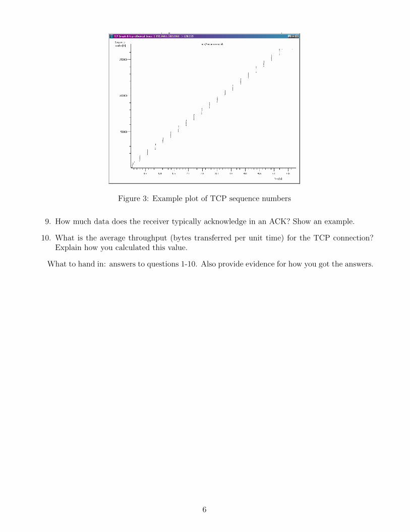
Figure 3: Example plot of TCP sequence numbers
9. How much data does the receiver typically acknowledge in an ACK? Show an example.
10. What is the average throughput (bytes transferred per unit time) for the TCP connection?Explain how you calculated this value.
What to hand in: answers to questions 1-10. Also provide evidence for how you got the answers.
6