ece597 special problems - upv/ehu
TRANSCRIPT

Due date: Saturday, July 28th, 2018
ECE597 – SPECIAL PROBLEMS
“COMPUTER VISION BASED TWO-WHEEL SELF-BALANCING
ROVER FEATURING ARDUINO AND RASPBERRY PI”
By Beñat Azkargorta
Under the supervision of Jafar Saniie and Boyang Wang
Signed:
Beñat Azkargorta
Contents ECE597 – SPECIAL PROBLEMS .......................................................................................................... 1
“COMPUTER VISION BASED TWO-WHEEL SELF-BALANCING ROVER FEATURING ARDUINO AND RASPBERRY
PI” .................................................................................................................................................. 1
Abstract: .................................................................................................................................... 3
Introduction: ............................................................................................................................. 3
Background: .............................................................................................................................. 4
Project Description: .................................................................................................................. 5
MPU-6050 ............................................................................................................................. 5
Decoder and Filter: Conversion of raw data into gesture information .............................. 9
PID Controller ....................................................................................................................... 9
Raspberry Pi® ...................................................................................................................... 14
Web Cam ............................................................................................................................. 14
Keyboard Commands .......................................................................................................... 15
PWM Controller .................................................................................................................. 17
Physical Structure ............................................................................................................... 18
Challenges: .............................................................................................................................. 22
Results: .................................................................................................................................... 23
Conclusion and Future Work: ................................................................................................. 23
References .......................................................................................................................... 25
Attachments: .......................................................................................................................... 26
Acknowledgements: ............................................................................................................... 26

Abstract: This project aims to design and implement a holistic control system to
build a portable self-balancing robot with two wheels that can have several
functionalities added to it, based on software implemented on the Arduino and
Raspberry Pi® processing units. Two of the functionalities added to this system are a PC
terminal remote control and a computer vision based algorithm, which is able to detect,
track, and chase objects. The system is highly scalable and has room for many other
ideas so that almost anybody can pick up where I left off and improve the existing
algorithms or implement new ideas on it. The focus of this project is mainly on the
control systems and algorithms, and not so much on the final robot product, which is
just a way to show how neatly the controls and algorithms work. The object of the
research was also understanding the inter-dependability and connections of several
different systems and being able to make them compatible under the same system.
Introduction: The original idea behind this project is based on an existing off-
the-shelf product developed by SainSmart. Hence, although the existing technology has
been enhanced and modified for our own purposes, some recognition must be delivered
to SainSmart, as part of the software and hardware were developed by them. The
product, available to the general public, goes under the name of “InstaBots Remote
Control Self-Balancing Robot” [1].
Figure 1: Final aspect of the rover, standing
The research was carried out in the Electrical & Computer Engineering
Department of the Illinois Institute of Technology, in Chicago, as the main task of the
course ECE597: Special Problems, and under the supervision of Dr. Jafar Saniie. In
particular, the research was done in collaboration and as part of the ECASP (Embedded
Computing and Signal Processing) Research Laboratory, tutored by one of its members,
Boyang Wang, to whom I owe the praise for being able to develop this project.

Needless to stay, the project would not have been possible without the
laboratory equipment and funding from the ECASP Research Team and the ECE
Department, or without the help of the professors and researchers involved in this
space.
The main duty this student had to accomplish for the first part of this course was
to become familiarized with the environment, tools, and knowledge necessary to be
able to manage such a complex and diverse system. For the first three months, during
the Spring semester, the work was only focused on documentation and developing
laboratory assignments of courses related to computing algorithms and FPGA design. In
fact, the original idea was to develop this same project based on an FPGA controller
instead of using the Arduino board for balancing control, but as will be explained later
on, the idea had to be dropped due to several difficulties. In the first report related to
this course, this student submitted the set of laboratory assignments designed for the
course ECE446 – Advanced Logic Design, which consisted of a set of assignments related
to hardware design.
Along with this report, several files will be submitted, such as the slides for a
presentation, the file for the AutoCAD designs comprising the physical structure, the
Arduino source code that governs the motor motion, and the two Python codes used by
the Raspberry Pi® to implement the functionalities of the remote keyboard controller
and the computer vision based algorithm for object tracking and chasing.
Some potential future work will be discussed at the end of this report too, to give
a few pointers of how this project could be continued or improved in the future.
Background: In a world where everything is becoming automatized, and
communication systems are implemented in more and more objects, like we see in the
IoT example, understanding and being able to make a wide variety of systems
compatible has become of utmost importance. Starting from the physics and
mathematics of the balancing, to the more advanced software used in a board with an
operating system such like the Raspberry Pi®, this project involves a rather deep
understanding of several fields, including hardware electronics.
This section was also intended to provide some background information about
the parts that comprise this project, such as the Arduino system, the Raspberry Pi®
single-board computer, the MPU-6050 accelerometer, or the PWM motor driver.
However, due to the already detailed explanations given in the following chapter,
Project Description, details will be omitted and the reader will be referred to said section
for further detailed descriptions.

Project Description: The project consists of a holistic system including different parts that
communicate with each other and are dependent on one another’s performance. The
following block diagram could illustrate the main scheme of the parts involved in the
project.
Figure 2: Block diagram of the project
MPU-6050
The MPU-6050 is the device in charge of the physical sensors utilized to balance
the system. This block’s only purpose is to sense the acceleration, inclination, and
rotation of the rover and provide an input of information to the Arduino processor so
that a real-time adjustment can be made thus keeping the robot from falling down.
The device is the world’s first integrated 6-axis MotionTracking device, and it
combines a 3-axis gyroscope, 3-axis accelerometer and a Digital Motion Processor™
(DMP) all in a small 4x4x0.9 mm package. The number of sensor inputs in an IMU are
referred to as DOF or Degrees of Freedom, so a chip with a 3-axis gyroscope and a 3-axis
accelerometer such as this one would be a 6-DOF IMU. For communication, it uses a
standard I2C bus for serial data transmission. [2]

An accelerometer is a device that is able to sense three-dimensional motion and
provide a numerical output to compute it. Proof of mass deflection is measured as a
change in capacitance between the proof mass and sensing plates, as shown in Figure 3:
Accelerometer circuitry. The internal circuitry converts the tiny capacitance to a voltage
signal, which can be digitized and output. Each accelerometer has a zero-g voltage level,
which should be found on spec, and computing orientation relies on a constant
gravitational pull of 1g (~9.81 m/s2) downwards. Besides that, each device usually also
has a sensitivity value, expressed in mV/g, and digital accelerometers such as this one
use a serial protocol like I2C, SPI or USART to communicate with the rest of the system.
In this particular project, as mentioned, we will use the MPU-6050 as a slave of a I2C
system controlled by the master located in the Arduino chip.
A gyroscope measures angular velocity, i.e. the rate of change in orientation
angle, but not angular orientation itself. For this, one must first initialize the sensor
position with a known value (possibly from the accelerometer), and then measure the
angular velocity (ω)around the x, y, and z axes measured at intervals (Δt). Hence:
ω x Δt = change in angle
The new orientation angle is the original angle plus this change
However, because this is obtained by integrating (adding up many small
computed intervals) to find orientation, repeatedly adding up increments of ω x Δt
results in small systematic errors becoming magnified over time. This phenomenon is
called Gyroscopic drift and it makes the gyroscope data increasingly inaccurate over long
timescales.
As Figure 5 shows, gyroscopes use the Coriolis effect to transform an angular
velocity into a displacement. The Coriolis Force acts perpendicular to the rotation axis
and to the velocity of the body in the rotating frame.
Figure 3: Accelerometer circuitry [10]
Figure 4: MPU-6050 and its three-dimensional axes

Fc = -2m Ω x v
The displacement induces a change in capacitance between the mass and the
housing, thus transforming the angular rate input to the gyroscope into an electrical
output.
One of the methods to deal with systematic errors in both of these devices is
called Sensor Fusion. An accelerometer measures inertial force, such as gravity, but it
might also be caused by acceleration (movement) of the device. Even if the
accelerometer is relatively stable, it is very sensitive to vibration and mechanical noise.
A gyroscope, on the other hand, is less sensitive to linear mechanical movements (the
type of noise that the accelerometer suffers from), but has other types of problems like
drift: not coming back to zero-rate value after rotation stops. Averaging the data that
comes from both can produce a better estimate of orientation than using accelerometer
data alone. For that, several algorithms exist, such as the Kalman Filter or the
Complementary Filter, that provide a weighted average, which results in more accurate
outputs. Figure 6 shows a graphic example of how the combination of the data from both
devices contributes to a better Pitch & Roll accuracy.
Figure 6: Sensor Fusion accuracy depending on vibration frequency [3]
Figure 5: Coriolis Forces on a Gyroscope [11]

As for the communication, we mentioned the device MPU-6050 uses the
protocol I2C to communicate between the master (Arduino) and the slaves (in this case
the accelerometer and the gyroscope). As Figure 7 shows, an I2C system may have
several devices. Generally, there will be multiple slaves, but there will only be one
master, who is in charge of driving the clock and initiating all transfers both ways. Both
master and slave can transfer data over the I2C bus, but the transfer is always controlled
by the master.
Figure 7: I2C block diagram [4]
There are two wires: SCL is the clock line, and is used to synchronize all data
transfers. SDA is the data line. Both lines are “open drain” drivers, which means they can
only be driven low, and a pull-up resistor attached to the voltage supply is necessary for
the line to go high. Figure 8 shows an example of this.
Figure 8: An "open drain" driver
Without getting too deep into explaining the procedures of the I2C protocol, it is worth
mentioning that the data is transferred in sequences of 8 bits, sent with the most significant bit
first, and the protocol possesses control mechanisms such as the start bit and the stop bit
(signaling the beginning and end of a transaction), and the acknowledge bit. The acknowledge
bit is sent by the slave right after each 8 bits transfer, therefore it takes 9 SCL clock pulses to
transfer each 8 bytes of data.
Each device on the bus has a unique I2C address, that is usually 7 bits long, allowing up
to 128 devices on the I2C bus. Addresses are sent in 8 bits, where the extra bit (the last one)
indicates read or write operations:
Zero the master is writing to the slave
One the master is reading from the slave
The standard SCL clock speed for I2C is up to 100 kHz.

Decoder and Filter: Conversion of raw data into gesture information The next block of our system consists of a processing unit inside Arduino that is
responsible for receiving the raw data coming from the MPU-6050, and converting it into useful
gesture information that we can utilize for decision-making. For this, it is necessary to convert
and filter the signals from the accelerometer and gyroscope.
The code for this block, as with the rest of the source codes, will be attached on a
separate file along with this document, in the Arduino source code. It is a set of mathematical
operations, written in a language similar to C++, that filters the serial data to raw angles and
values first, and then gives a filtered angle converted to degrees and acceleration and rotation
values for all 3 axes x, y, and z. This gesture information can then be used to infer the position
of the rover and adjust the power and direction of the motors driving the wheels to make the
machine stand upright.
In essence, the input of this block is serial data coming from the MPU-6050, and the
output should be the x,y, and z co-ordinates of the accelerometer and gyroscope, as seen on
Figure 4, and ultimately a filtered angle that will indicate the inclination of the rover. Then this
output can be used as an input of the PID controller, which, compared to the desired setpoint,
will give us an error signal e(t) with which we will be able to compute the calculations for self-
balancing and gesture correction.
PID Controller While the original project developed by SainSmart already had a fairly simple but
working PID controller written on the Arduino processor, our goal was to improve that one to
end up with an efficient, robust algorithm. The following lines will be used to explain what a PID
controller is and how we were able to devise an advanced PID starting from the simplest form.
In order to fulfill this goal, we will make use of the updated PID library for Arduino, available for
free on Arduino’s official website [5], and we will explain the advantages that this standardized
library has over the basic PID designed originally by SainSmart.
PID stands for proportional-integral-derivative, and it is a control loop feedback
mechanism widely used in industrial control systems and a variety of other applications
requiring continuously modulated control. A PID controller continuously calculates and error
value e(t) as the difference between a desired setpoint (SP) and a measured process variable
(PV), and it applies a correction based on the proportional, integral, and derivative terms of the
error (denoted P, I, and D respectively). In practical terms, it automatically applies accurate and
responsive correction to a control function.
Each terms has a weighted coefficient, so that the arithmetic of the continuous
operation would look like the following formula expressed in Figure 9.
Figure 9: PID arithmetic

Developing a code based only on this operation could give satisfactory results, but there
are a few factors to take into account when developing a robust and reliable industrial control
system: [6]
Sample time: The PID algorithm functions best if it is evaluated at a regular interval. If
the algorithm is aware of this interval, it is also possible to simplify some of the internal
math.
In the case of the original algorithm, we can see by observing the code that this issue is
already taken care of, as the reading of the values from the MPU-6050 happens exactly
every 1,000 cycles.
Derivative Kick: This is a phenomenon caused by the spikes in the signal of derivative
error, which result in spikes in the output signal also. It happens often, for instance,
when the setpoint is modified by the user, as we can see in Figure 10.
Figure 10: Derivative Kick [6]
In order to ameliorate this, we change the equation of the derivative error from this:
𝑑 𝑒(𝑡)
𝑑𝑡 =
𝑑 𝑆𝑒𝑡𝑝𝑜𝑖𝑛𝑡
𝑑𝑡 -
𝑑 𝐼𝑛𝑝𝑢𝑡
𝑑𝑡 to this:
𝑑 𝑒(𝑡)
𝑑𝑡 = -
𝑑 𝐼𝑛𝑝𝑢𝑡
𝑑𝑡
which is the equivalent of the equation when the setpoint is constant. This means the
derivative of the error is equal to the negative derivative of the Input except when the
setpoint is changing. Taking the setpoint out of the equation, we get rid of the spikes
from the changes of setpoint, as we can see in Figure 11. That way, the PID will work just
as well, but will rely on the value of the previous input instead of the previous error.

Figure 11: Derivative Error without the setpoint component [6]
This technique is known as using “Derivative on Measurement”.
On-The-Fly Tuning Changes: A good PID algorithm is one where tuning parameters can
be changed without jolting the internal workings. In our system, although we do not
plan to interactively change the PID coefficients while running, it seems a good feature
to add just in case for a well-thought PID algorithm.
However, when doing so, we can observe the integral component suffers a significant
bump, due to the fact that Ki is multiplying the entire error sum accumulated so far (all
the previous components), so when Ki changes the difference is amplified by the
accumulated error. Ideally, when changing parameters, the goal would be to only affect
things going forward, and not previous values.
To fix this, we can create a temporary variable for the values of “Ki * error” and add this
to the error sum. This way, the sum of errors will have already included the current
coefficient into account and we won’t have to multiply the whole error sum by the later
coefficient, as we did before. In other words, the equation goes from being equation a)
from REFERENCE to equation b) from REFERENCE. At first sight, it seems like nothing
changes because the equations are equivalent, but it makes a big difference. In equation
b) the momentary coefficients are multiplied by each term end the error is stored in the
sum, in equation a) all errors are summed up and then multiplied by the latest
coefficient. With a changing coefficient, the difference is obvious.
Figure 12: Integrating errors to obtain error sum, two different approaches
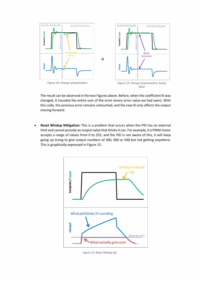
The result can be observed in the two Figures above. Before, when the coefficient Ki was
changed, it rescaled the entire sum of the error (every error value we had seen). With
this code, the previous error remains untouched, and the new Ki only affects the output
moving forward.
Reset Windup Mitigation: This is a problem that occurs when the PID has an external
limit and cannot provide an output value that thinks it can. For example, it a PWM motor
accepts a range of values from 0 to 255, and the PID is not aware of this, it will keep
going up trying to give output numbers of 300, 400 or 500 but not getting anywhere.
This is graphically expressed in Figure 15.
Figure 15: Reset Windup [6]
Figure 14: Change of parameters Figure 13: Change of parameters, bump fixed

One effective method to solve this could be to establish the limits for the PID output so
that the system is aware of the usable range and the computed values are always
proportional and within range. In our case, the PID code was improved by adding a
function named “SetOutputLimits”, which is in charge of performing the desired task.
With this enhancement, the value of the output pin would resemble the one that can be
seen in the bottom image of Figure 16.
Figure 16: Reset Windup fixed [6]
On/Off (Auto/Manual): In most applications, there might be times where it is desirable
to turn off the PID controller and adjust the output by hand, without the controller
interfering. This might be useful for calibrating or testing purposes. This functionality
was added by adding a section of code which allows the PID to be on (Automatic mode)
or Off (Manual mode). In the latter, the Output can be manually set regardless of the
input value or the previously computed output value of the PID.
Initialization: When the controller first turns on, ideally a ‘bumpless’ transfer should be
obtained. This is, the output should not suddenly jerk to a new value. This is already
done successfully in the original code developed by SainSmart, by simply running a
couple hundred of cycles previous to starting the program’s regular routine. This way,
before the output is enabled, a few input values from the sensor are computed and the
output signal is stabilized. When it is already stable, the output can be activated and the
user will only see a steady signal without any violent jerks.

Controller direction: PID processes will have two ways of acting upon the output
devices, in this case, the motors: direct acting and reverse acting. Making sure the
parameters, such as the coefficients, are operated with the correct sign is of vital
importance. This can be an easy fix, just be using absolute values for the parameters and
clearly stating the sign of the operations.
This measure is already taken in the original code, but it was our job to double-check
the operations were properly executed.
Adaptive tunings: One of the benefits of the updated PID library is that the tuning
parameters can be changed accordingly in real time. This can be helpful if one wants the
controller to be more aggressive at some times, and more conservative at others. For
instance, in our example we set the K coefficients to be more conservative when the
input value is near setpoint and more aggressive when it is further away.
As we can see in the attached code, we established different coefficients for different
situations, having three aggressive Kp, Ki, and Kd, with a bigger absolute value than the
conservative Kp, Ki, and Kd. This improves the balancing performance significantly.
Raspberry Pi® The Raspberry Pi® is a small single-board computer that can be connected to several
peripherals such as a keyboard, a monitor, and a Wi-Fi router thus making it a perfect candidate
for us to implement more sophisticated code from a distance while having a very simplistic
model installed on our rover.
The main purpose of this board is to receive and process input signals coming from the
Web Cam and/or the command terminal from a PC, and to communicate those to the Arduino
board via USB in order to govern the motion of the rover. The block diagram of Figure 2 displays
this idea.
Web Cam The Web Cam is connected via USB cable to the Raspberry Pi®, and through a few simple
existing algorithms we are able to implement object tracking or obstacle avoidance features to
our rover. This code is written in Python and also attached with this document.
The main functionality of the camera is going to be recognizing and tracking an object
(for instance a red foam ball) and to send commands to the Arduino board so that the rover
follows it. Existing libraries on OpenCV make perfect candidates for this use, so this student
analyzed them, adapted them to our own system, and debugged them in order to obtain an
efficient algorithm that is able to keep up with the objective.
In this case, unlike in the next chapter, we will connect a PC to the Raspberry Pi® via
Remote Desktop. The reason being that the libraries that detect object allow us to display the
images of the camera with the tracking objects being highlighted by colorful signs; but none of
this is useful if we do not have a monitor where we can see the display of the Raspberry Pi®.
Since the board will be independent and wireless (so that it can move freely), we will use Wi-Fi
connection to access the Remote Desktop and that way we’ll be able to monitor the object
tracking and make sure it is doing its job properly.

The object tracking algorithm chosen for this task is based on the Hough Transform, and
it is free and available for everyone to obtain online on the OpenCV library. This algorithm only
detects shape and color, so it is nowhere near perfect, but it does a good enough of a job to
keep track of objects such as a red ball, for demonstration purposes.
As for the object chasing algorithm, it was created from scratch by this student on the
lab, by implementing a series of orders based on the position of the detected object on the
screen. Basically, if the center of the object detected is on the left side or right side of the screen,
the rover will turn to the opposite side until the object is centered on the screen. Only then,
when the object is centered, will the rover decide to move forward and approach the object. If
the object’s radius on the screen is small enough (meaning that the object is far enough), the
tracking pointer will appear in green, and if the object is centered, the rover will move forward
towards it. On the contrary, if the object is close (its radius is bigger), the tracking sign will appear
in red and the rover will not move forward. However, if the object is on one side or another of
the screen, even if it is close and it appears in red, the rover will turn to face it directly, but it will
not move forward to get any closer to it.
In order for the Raspberry Pi® to allow Remote Desktop access to our PC, we will have
to previously install the xrdp library, by typing the following command on the terminal, while
having a working Internet connection, of course:
sudo apt-get install xrdp
The following figure shows the display of the object detection algorithm as the camera
captures footage of myself holding a red frisbee. As we can see, the algorithm does a pretty
good job recognizing and tracking the red, round object.
Figure 17: Object tracking software on Raspberry Pi® using Remote Desktop
Keyboard Commands Another feature that the Raspberry Pi® board allows us to do is to be able to control the
motion of the rover by inputting commands from the terminal of any PC. In order to do this, we
connect any PC to the Raspberry Pi® board via ssh communication over a Wi-Fi router (although
this could be done by direct Wi-Fi connection), and we execute a Python code which was

developed from scratch to intake commands from the user and send them serially to the motor
controller board. The ssh communication can be done by using an application such as PuTTY or
simply by typing ssh commands from the terminal. After that, the commands are sent to the
Arduino board, which is continuously listening to the serial connection. The Arduino board
should contain some functions in its code that are responsible for receiving and processing this
data and govern the PWM controller accordingly. The physical connection between the
Raspberry Pi® and the Arduino board is made by an USB cable and the parameters of it are as
follows:
Port: ttyACM0 (important to set the correct USB port)
Baudrate : 115200 symbols/s
Parity bits: none
Stopbits: one
Bytelength: eight bits
These parameters, although they seem very basic, are very relevant, because this is the
format of serial communication the Arduino board will be expecting, and it is of the uttermost
important that both boards ‘speak the same language’.
As for the commands, this design includes a set of eight commands that are activated
by inputting a character from the keyboard and function as follows.
‘I’: move forward
‘K’: move backwards
‘J’: turn left
‘L’: turn right
‘N’: spin left
‘M’: spin right
‘S’: stop spinning
‘X’: stop displacement
The Python code used in the Raspberry Pi®, as well as the C++ code used in the Arduino
will both be attached for a deeper comprehension of the communication algorithms.
Figure 18: Raspberry Pi® board

PWM Controller The PWM controller is the block in charge of controlling the direction and power of the
motors by asserting them signals modulated with Pulse Width Modulation (PWM). In essence,
this modulation controls the power of the motor by means of the Duty Cycle, which is the
percentage of time for which the signal that drives the motor is asserted. This is shown
graphically in Figure 19, where a 0% duty cycle shows the driving signal low all the time, thus
not moving the motor, and a 100% duty cycle has the input signal asserted at all times, hence
running the motor at full speed. In our case, the duty cycle is a value between 0 and 255, an 8-
bit value.
Figure 19: Pulse Width Modulation [7]
The output value of the duty cycle is dependent not only on the input values obtained
from the accelerometer and the gyroscope, but also on the values of the ‘speed’, ‘turn speed’,
which can be manually adjusted by the user by using commands coming from the Raspberry Pi®,
or by the information gotten from the Web Cam. Id est, the motors are governed according to
the PID controller in order for the rover to stand upright, but that only controls the balance of
the device, whereas the orders for the rover to move back and forth or turn would have to come
from the Raspberry Pi® (whether they are obtained from the Web Cam or input manually by the
user). The block diagram seen at Figure 2 shows a global picture of the system which could help
understand the flow of information of the project.

Therefore, any type of information relevant for the rover to move, has to come through
this block, because this block is what ultimately tells the motor what to do; that is, which motor
to activate (left or right), with how much power, and in what direction.
It is worth mentioning that, the electronic chip that was chosen for the purpose of
driving the motor is the microchip TB6612, commercialized by SparkFun and, in our case,
delivered by Digi-Key Electronics USA.
Physical Structure The physical structure of the project is based on the original idea developed by
SainSmart but was further developed and enhanced to meet our own goals. The design consists
of four layers, one more than the original, and the following paragraphs contain a description of
what could be found in each of these layers.
The PVC boards that separate each layer were redesigned to better fit our demands and
replaced with a thicker, stronger, PVC material to prevent the bending or cracking of the
structure due to the weight that it supports. Design changes include the following:
The bottom board had to be stretched out in order to fit the new motors, which were
bought to replace the old, worn out motors of the original SainSmart system, and were
larger than the originals.
The drill holes designed for the motor holders were also slightly misaligned and were
redesigned to perfectly fit the measures of the real units.
The holes designed for the motor wirings were shrunk, so that the wirings are barely
able to pass through, but the overall resistance of the board is greatly enhanced.
A top board was added on top of the battery to sustain both the Raspberry Pi® and the
Microsoft® Web Cam.
The graphic designs of these boards were designed using AUTODESK® AutoCAD® 2016
and brought to reality by the use of a laser cutter on campus. All the files containing the designs
are also attached along with this report.
Figure 20: AutoCAD design of the PVC boards
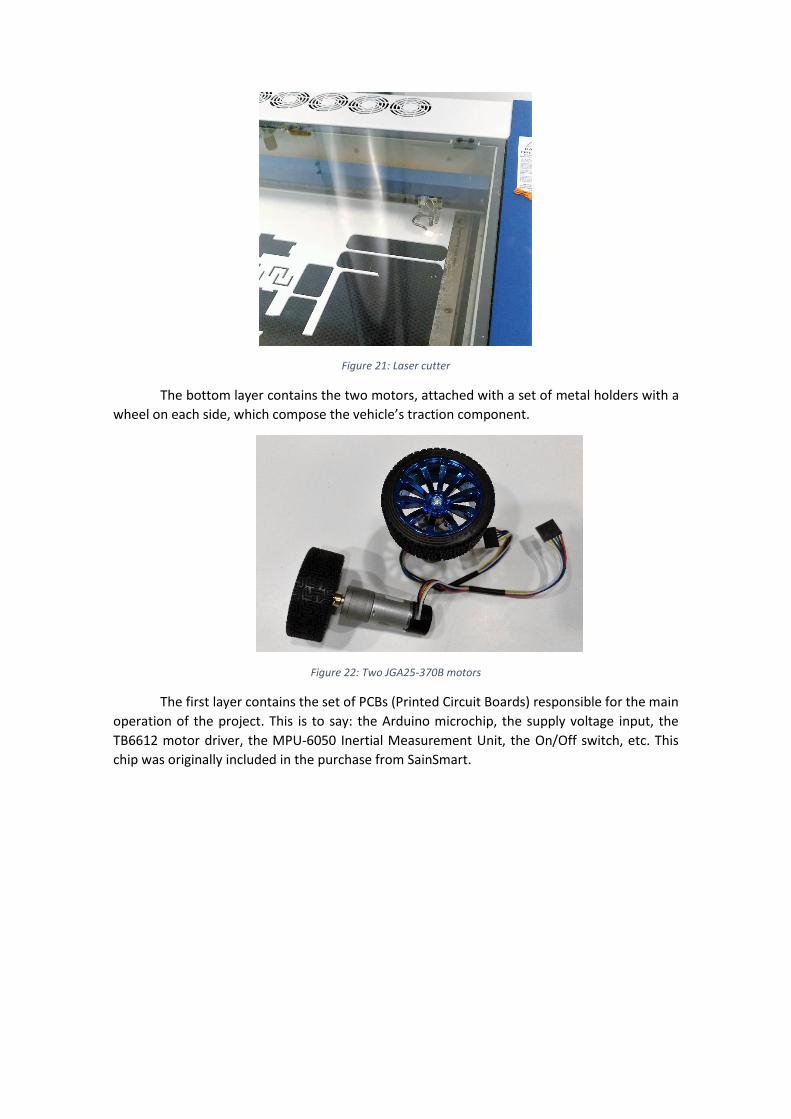
Figure 21: Laser cutter
The bottom layer contains the two motors, attached with a set of metal holders with a
wheel on each side, which compose the vehicle’s traction component.
Figure 22: Two JGA25-370B motors
The first layer contains the set of PCBs (Printed Circuit Boards) responsible for the main
operation of the project. This is to say: the Arduino microchip, the supply voltage input, the
TB6612 motor driver, the MPU-6050 Inertial Measurement Unit, the On/Off switch, etc. This
chip was originally included in the purchase from SainSmart.

Figure 23: Main board with Arduino, MPU-6050, TB6612, etc.
This board, however, was designed with a faulty layout and a security adjustment had
to be made. The LB-Link connector underlying the pins for the motor was in contact with those
pins, and since it had a metal surface, it created a short-circuit between all of the pins for Motor
1. In order to fix this, this student used a caulk gun and covered all the pins with silicon with the
intention of avoiding any non-desired contact which would lead to potentially burning some of
the components of the board. The final result is visible in Figure 24.
Figure 24: Caulk gun being used to cover motor pins
The second contains a 11.1 V battery, responsible for supplying the power for the entire
system, attached with a couple of Velcro strips to the PVC structure.

Figure 25: Battery with 11.1 V DC output
And the top layer is comprised by the Raspberry Pi® board and the Microsoft® Web Cam,
which is at the same time connected to the Raspberry Pi® as an input sensor.
The layers are assembled together in a structure made possible by using the PVC boards
as bases and a set of several nuts and bolts as connectors. Figure 26 shows the final aspect of
the project.
Figure 26: Physical structure of rover

Challenges: A few challenges were encountered in the realization of this project, which led to
changes in plans, goals, and even deadlines. The original idea was to develop the project in VHDL
language using an FPGA system based on the board PYNQ™-Z1 by Xilinx, seen in Figure 27.
Figure 27: PYNQ™-Z1 by Xilinx
However, due to the difficulty of the project, the time constraints, and frankly the lack
of expertise of this student in FPGA areas as specialized as this, the idea had to be dropped, after
consulting with Mr. Wang, the most proficient instructor in the FPGA area.
The preparation work for this project carried out in the Spring semester was all directed
towards FPGA preparation, as can be inferred by the report submitted for ECE597 in Spring.
Nevertheless, after the student encountered more problems than expected, a change of plans
seemed inevitable.
Even after that, a few more problems came up. This student in particular burnt one of
the motors and a TB6612 motor driver due to the incorrect connection of pins, so the lab had to
spend extra revenue in new material for the realization of this project.
More hardware problems were also noted, such as the output voltage of the battery,
which seemed to be worn out by use, and did not give anywhere near the desired 12 V (in fact
it ranged between 7.12 V and 7.58 V, depending on the charge). This students suspects that the
reason behind the deterioration of the battery might have been the faulty physical design by
SainSmart mentioned in the physical structure description, which created a short circuit
between the motor pins and thus was demanding an enormous amount of current continuously
from the battery. This problem’s solution was shown in Figure 24.

The older, worn out hardware created a relatively critical problem when carrying out
the testing of the codes, because the student was not sure if the incorrect functioning of the
system was due to the hardware (apparent lack of power when driving the motor) or the Arduino
code was just not good enough for balancing the system. This gave the student more than one
headache.
Results: The result is essentially a self-sufficient wireless balancing robot, which is controllable
through instructions from another PC, and able to detect, track, and chase objects automatically.
As mentioned before, Wi-Fi connection is necessary for the communication between the PC and
the Raspberry Pi® (via ssh or Remote Desktop) and the communication between the latter and
the Arduino board is done serially over a USB cable.
The project is easily scalable by adding or improving the Python algorithms on the
Raspberrry Pi®, meaning that it has potential continuity.
The final aspect of the project can be seen in Figure 26, but it is somewhat difficult to
show the proper functioning of it in a report. Hence, the university of IIT, through Dr. Saniie,
scheduled an official demonstration carried out on the 26th of July of 2018 on the Illinois Institute
of Technology campus, Electrical and Computer Engineering Department. That will provide
proof of the performance of the project for the record. The demonstration, as well as the
presentation carried out by this student to explain the project in detail, will be recorded on video
and posted on the ECASP Research Team’s website for anyone to see.
Conclusion and Future Work: The project offers a final working product, but more importantly, a research of
several control systems and codes, and a holistic system integrating several peripherals.
It is important to note that the object of a research project is not to sell a product, but
to learn about a particular subject, so even if the result of this project was inconclusive,
and it was not possible to make the robot work; or furthermore, even if the conclusion
of this research was that it is not possible to make such different systems compatible;
we could consider this a satisfactory research, due to the amount of information learnt
and the diverse nature of the environments that this student had to get familiarized
with.
As mentioned above, none of this would have been possible without the
inestimable help of the members of ECASP and the ECE Department, and of course the
funding and equipment provided by them.
As for the future works, there is a particular proposal that I started working on,
but could not present due to time constraints: A set of algorithms called ARUCO and
developed by a group of researchers from Cordoba, southern Spain. It consists of an
OpenSource library for camera pose estimation using squared markers. ARUCO is
written in C++, but can be converted to Python, and is extremely fast. An example of a
functionality that could be implemented with ARUCO is the detection of several shapes
such as the ones seen on Figure 28, in which each of the shapes could represent a
command, and make the motors of the rovers act accordingly, depending on the shape
they see. This objects is also able to detect rotation, semi-covered objects, etc.

Figure 28: shape codes for the ARUCO library

References
[1] Sainsmart. [Online]. Available: https://www.sainsmart.com/products/instabots-remote-
control-self-balancing-robot.
[2] U. o. N. C. Asheville, "Using the MPU-6050. Inertia measurement systems," [Online].
Available: www.cs.unca.edu/~bruce/Fall13/360/IMU_Wk8.pptx.
[3] Memscentral. [Online]. Available:
http://memscentral.com/Secondlayer/mems_motion_sensor_perspectives-sensor-
susion-high-res.htm.
[4] Robot-electronics. [Online]. Available: http://www.robot-
electronics.co.uk/acatalog/I2C_Tutorial.html.
[5] Arduino, "Arduino Playground PID," [Online]. Available:
https://playground.arduino.cc/Code/PIDLibrary.
[6] B. Beauregard, "Improving the beginner's PID," [Online]. Available:
http://brettbeauregard.com/blog/2011/04/improving-the-beginners-pid-introduction/.
[7] Arduino, "Arduino Playground PWM," [Online]. Available:
https://www.arduino.cc/en/Tutorial/PWM.
[8] N. H. W. a. D. M. Harris, CMOS VLSI Design. A Circuits and Systems perspective,
Pearson/Addison-Wesley, 2005.
[9] J. Charles H. Roth, Digital Systems Using VHDL, Cengage Learning, 2008.
[10] Freescale. [Online]. Available:
http://www.freescale.com/files/sensors/doc/app_note/AN3461.pdf.
[11] Digikey. [Online]. Available:
http://www.digikey.com/us/en/techzone/sensors/resources/articles/MEMS-
Accelerometers.html.

Attachments: Attached along with this document, on separate files, are:
Source code for the Arduino controller
Python codes used on the Raspberry Pi® for:
o Keyboard commands and serial communication
o Object tracking and following algorithm
AutoCAD® footprints of the boards used for assembling the rover
Presentation slides summarizing this report
Acknowledgements: I feel obliged to send a special thank you to Boyang Wang for his help and patience,
without which I would never be able to fulfill any part of this project. Another thank you goes to
Dr. Jafar Saniie, for making sure progress was being made at all times, and for providing us with
certain flexibility, thus making it easy for us to meet the deadlines. Thank you also to the ECASP
Research Group and the Electrical & Computer Engineering Department for funding this project
and providing with the laboratory equipment necessary to carry it out.
I also feel the need to mention Mr. Craig Johnson, Head of Machine Shop & Coordinator
of the Student Fabrication and Design Studio, without whom I would not be able to print or cut
any of the PVC boards that comprise the structure. And Alejandro Vazquez, for giving me a hand
with his coding vision to improve the Python algorithms.
And last, but not least, to my mother for pushing me forward on a daily basis and giving
me the strength to keep working.