ecet senior design project report - iupui
TRANSCRIPT

Indianapolis Motor Speedway Display Project 1
Xtrac
ECET SENIOR DESIGN PROJECT REPORT
Indianapolis Motor Speedway (IMS) Display Project
Submitted to
Professor Robert Weissbach
Professor William Lin
Electrical Engineering Technology Program
Engineering Technology Department
by
Charleston Shi and Cristobal Ibanez
December 10, 2019

Indianapolis Motor Speedway Display Project 2
Xtrac
Document Information
Title: IMS Display Qualification Testing
Author: Charleston Shi and Cristobal Ibanez
File Name: FINAL REPORT
Revision History
Date Initials Version Section Updated Notes
9/17/19 C.S 1.0 Document Created
8/1/19 C.S 2.0 Updated signatures
11/15/19 C.S 3.0 FINAL REPORT Pre-Final Presentation
12/5 C.S 4.0 FINAL REPORT Post-Final Presentation

Indianapolis Motor Speedway Display Project 3
Xtrac
Table of Contents
Document Information ........................................................................................... 2
Revision History ......................................................................................................................... 2
Definitions ................................................................................................................................... 5
Executive Summary .................................................... Error! Bookmark not defined.
Introduction ........................................................................................................... 7
Specification Requirements ..................................................................................... 8
Out of Scope ............................................................................................................................... 8
Assumptions ............................................................................................................................... 8
Related Projects ......................................................................................................................... 8
User Roles and Responsibilities ................................................................................................ 9
Process Overview .................................................................................................. 10
Current Process (System) ........................................................................................................ 10
High-Level Design ................................................................................................ 11
System Components ................................................................................................................. 11
Concept of Execution ............................................................................................................... 12
Interface Design ....................................................................................................................... 23
Low Level Design ................................................................................................. 24
Hardware .................................................................................................................................. 24
Interface .................................................................................................................................... 26
Setup and Operation ............................................................................................. 27
Qualification Testing ............................................................................................ 28
Test Plans ............................................................................................................ 30
Conclusion ........................................................................................................... 36
Recommendations ................................................................................................. 36
References ........................................................................................................... 37

Indianapolis Motor Speedway Display Project 4
Xtrac
Table 1 - Definitions .......................................................................................................... 5
Table 2 - User roles and responsibilities ............................................................................ 9
Table 3 – Board Selection Matrix ..................................................................................... 24
Table 4 – Power Supply Selection Matrix......................................................................... 25
Table 5 – Coding Language Selection Matrix .................................................................. 25
Table 6 – Standards and Related Documents ................................................................... 37

Indianapolis Motor Speedway Display Project 5
Xtrac
Definitions
The following definitions, acronyms, and abbreviations are found in this document:
Table 1 - Definitions
Term Definition
CAN Bus Standard designed to allow microcontrollers and
devices to communicate with each other in
applications without a host computer
IMS Indianapolis Motor Speedway; referring to the
museum
PLC Programmable Logic Controls
LCD Liquid Crystal Display; referring to the display
screen on the steering wheel
Xtrac Referring to the sponsor
IndyCar Premier level of open-wheel racing in North America

Indianapolis Motor Speedway Display Project 6
Xtrac
Abstract
The Indianapolis Motor Speedway Museum and Xtrac want an interactive display of a racecar
transmission and allows people of all ages to witness learn. Xtrac has commissioned IUPUI
engineers to create a control box that correlates to other functions of a racecar and then
correspond said box to a steering wheel, with additional features specified by the sponsor. Since
a transmission has mostly a mechanical aspect, Mechanical Engineering Technology (MET)
students are paired with a team of EET/CPET students. Any mounting and specification
requirements are a part of the MET students’ project requirements. Details regarding electrical
power, circuit design, and electromechanical integration will be generated by the EET students.
Keywords: ECET, Python, Xtrac, PLC, code, museum, transmission box, microcontroller,
steering wheel, testing, IMS, IndyCar, Captstone

Indianapolis Motor Speedway Display Project 7
Xtrac
Introduction
The Indianapolis Motor Speedway (IMS) Museum has a display transmission that is still actively
used in IndyCar today. The museum desires to create an interactive display that incorporates this
transmission so visitors of all ages can see internal gears spin as well as see the transmission shift
between its gears. The transmission will have a user-friendly interface of an actual racecar
steering wheel that will send signals to and fro the transmission, allowing museum guests of all
ages to shift gears, change speed, and turn the transmission on and off. The outcome of this
project is a failsafe and robust system that will operate within specifications set by the IMS
Museum while being continuously updated.
Xtrac has commissioned IUPUI engineers to create a museum-quality interactive simulation of a
racecar to be put on exhibit for the Indianapolis Motor Speedway Museum. For this project, we
will be primarily focused on corresponding a racecar steering wheel to the control box, with
additional features specified by the sponsor. Both steering wheel and engine control box are
materials that have been donated for our project. It should be noted that we are also inheriting
projects from previous engineer teams, and thus are trying to simultaneously reconcile various
design choices in order to better the already existing project. By the end of the Fall 2019
semester, we are expecting the project to be completed and be placed on display at the IMS
Museum.
The overall objective of the IMS Project is to develop or redesign an interface of a racecar
steering wheel with an engine control box. The resulting connection should send signals back
and forth between steering wheel and engine. Critical information should be displayed on the
screen and the LED lights. Certain aspects of the scope will include integrating the steering
wheel with the control box utilizing CAN Bus. The expected supply voltage and supply current
for the steering wheel is 10-18 V and 230 mA, respectively. You will shift gears using 6 steering
wheel buttons and/or 2 paddle and display information on the steering wheel (using screen
controls to shift gears and LED indicators to determine when to shift gears). This process will be
done by connecting the information from the gearbox and sending it through a Raspberry Pi 3B
to do necessary calculations then converting the information into CAN bus for the steering wheel
to read.

Indianapolis Motor Speedway Display Project 8
Xtrac
Specification Requirements
The objective of the IMS Project is to develop or redesign programmed interface of the donated
steering wheel in order to interface with a control box that manipulates a motor display and
displays critical information by the end of Fall 2019 semester. Certain aspects of the scope will
include:
Integrating the steering wheel with the control box utilizing CAN Bus. The expected
supply voltage and supply current for the steering wheel is 10-18 V and 230 mA,
respectively.
Shift gears using 6 steering wheel buttons and/or 2 paddles.
Display information on the steering wheel
o Using screen controls to shift gears
o LED indicators to determine when to shift gears
Out of Scope
The following items are outside the scope of this effort:
Design of the screen on the steering wheel
Identification/color of buttons
As of 2019, the current engineering technology design students have since inherited the project
left behind by the previous electrical design group.
The task will now be to correct the actuator that influences the gearbox before interfacing with
the microcontroller. This task is not considered
Assumptions
The final setup will be as a simulated display of a racecar engine on a museum that will see
communication between a steering wheel and a gearbox transmission. Regular maintenance and
supervision will be done.
Gentle usage of the display per museum rules to prolong the life of the display is suggested for
all operators and users.
Related Projects
Mechanical engineer technology design students are in charge of three main points:
redesigning/modifying the linkage between the actuator and the gear shift, designing the safety
box, and the steering wheel mount.
Another group of electrical engineer technology design students are in charge with the entirety of
the project and are in the process of designing ladder logic in connected components workbench
primarily.

Indianapolis Motor Speedway Display Project 9
Xtrac
User Roles and Responsibilities
Table 2 - User roles and responsibilities
Role Responsibility
Programmer Responsible for researching and programming
code
Researcher Compile and compose all data for
documentation and presentation
Tester Take measurements and data from
experimentations

Indianapolis Motor Speedway Display Project 10
Xtrac
Process Overview
Current Process (System)
The display is separated into three projects. It begins with the engine, within the engine a device
will be added to shift the gears mechanically. Next a control box will be added to the display to
control the engine’s gears with the added device as well as take information from the engine i.e
(rpm, temperature, current gear shifted). Lastly, the part of the project currently being address is
to take the information from the control box and display it to a donated steering wheel from
Cosworth. This steering wheel will also send information to the control box to change gears on
the engine and control the rpm.
This process will be done by connecting the information from the gearbox and sending it through
a Raspberry Pi 3B to do necessary calculations then converting the information into CAN bus for
the steering wheel to read. To shift gears, 2 pins will be used to output signals from the paddle
shifters to the Raspberry Pi or directly to the control box if possible to then shift the gear up or
down.

Indianapolis Motor Speedway Display Project 11
Xtrac
High-Level Design
System Components
As represented in Figure 1, the engine will send signals through the PLC in the control box,
which will direct said signals to a microcontroller. Through CAN communications, the
microcontroller interfaces with the steering wheel and display any measurements analyzed from
the signals on the LCD screen and LEDs. Interacting with the push buttons and the paddles on
said steering wheel will send signals to the steering wheel display and sent signals back through
the microcontroller with CAN communications to the control box to the engine.
Figure 1: Hardware Flow Diagram

Indianapolis Motor Speedway Display Project 12
Xtrac
Concept of Execution
As displayed in Figure 2, when the engine starts, the LCD display will showcase elements (RPM,
speed, gear shift, etc...). Through event handlers and interrupts, the program will send data to the
control box and update the LCD display per the button chosen.
Figure 2 – Software Flow Diagram

Indianapolis Motor Speedway Display Project 13
Xtrac
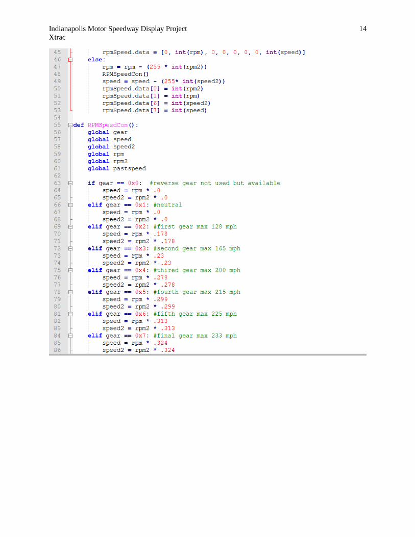
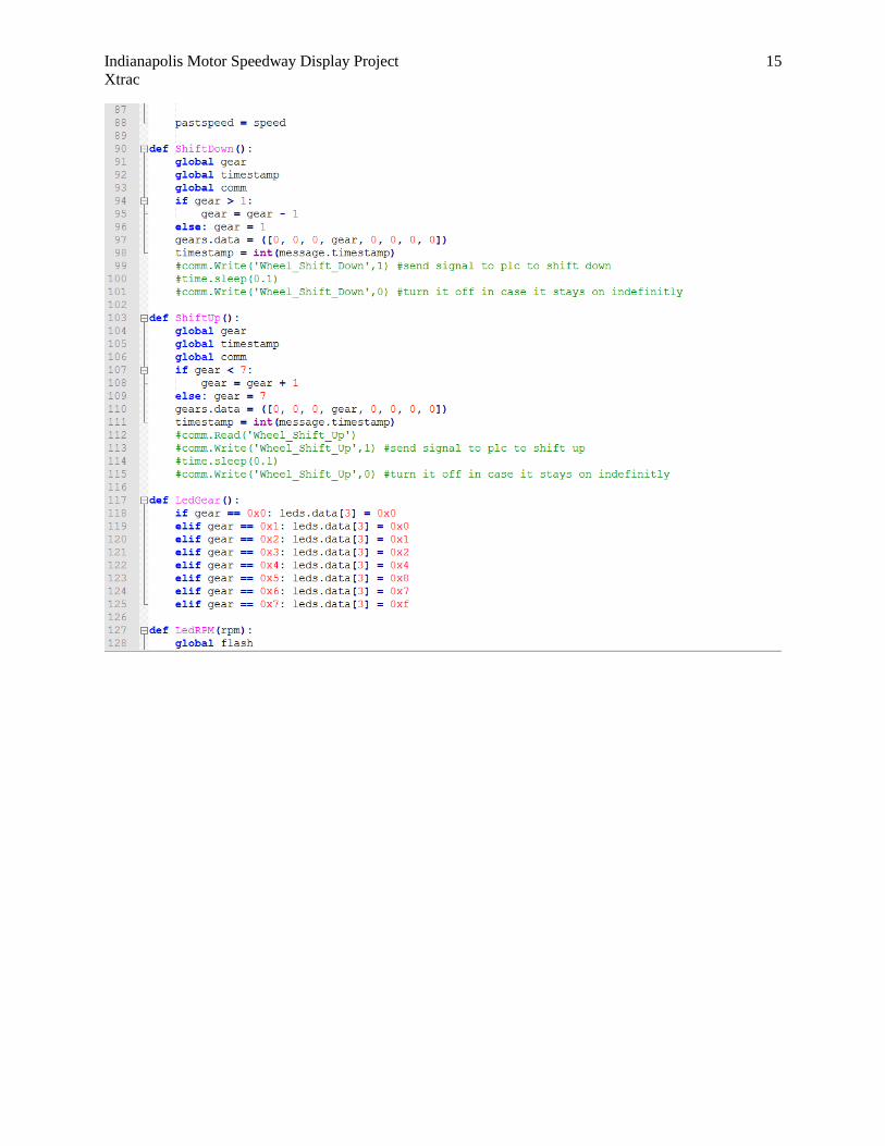
Fig 3- Python code for Steering Wheel and CAN interface
Indianapolis Motor Speedway Display Project 14
Xtrac
Indianapolis Motor Speedway Display Project 15
Xtrac

Indianapolis Motor Speedway Display Project 16
Xtrac

Indianapolis Motor Speedway Display Project 17
Xtrac

Indianapolis Motor Speedway Display Project 18
Xtrac
Figure 4- Connected Components Workbench Software (CCW)

Indianapolis Motor Speedway Display Project 19
Xtrac
Figure 5- PLC Input/Output

Indianapolis Motor Speedway Display Project 20
Xtrac
Figure 6: Control Box Schematic – Power and Inputs

Indianapolis Motor Speedway Display Project 21
Xtrac

Indianapolis Motor Speedway Display Project 22
Xtrac

Indianapolis Motor Speedway Display Project 23
Xtrac
Interface Design Below showcases the interface of the steering wheel with the respective inputs and outputs per the
schematic.
Figure 7 – Schematic of Steering Wheel Display
The steering wheel has eight separate digital switch inputs (6 buttons on the front and 2 paddles
on the back) as displayed in Figure 1:
Both Button 1 (S1) and Paddle 1 (P1) will shift the gears down
Button 2 (S2) starts/stops the motor
Button 3 (S3) changes pages on the display
Both Button 4 (S4) and Paddle 2 (P2) shifts the gear up
Button 5 (S5) LEDs from RPM to gear
Button 6 (S6) simulate acceleration.
There are 8 shift light LED’s at the top of the wheel which configure into 4 pairs (SL1-SL4)
LED 1 and 2 GREEN (SL1) represents when gears are in first shift
LED 3 and 4 GREEN (SL2) ) represents when gears are in second shift
LED 5 and 6 ORANGE (SL3) ) represents when gears are in third shift
LED 7 and 8 ORANGE (SL4) ) represents when gears are in fourth shift
When SL1 and SL2 are on, the gears are in fifth shift
When SL3 and Sl4 are on, the gears are in sixth shift
When all LEDs are on, the gears are in neutral shift.

Indianapolis Motor Speedway Display Project 24
Xtrac
Low Level Design
Hardware
As displayed on the Board Selection Matrix below, the hardware interface was chosen based on
the factors of price, built-in CAN interface, CAN peripheral, library supported CAN chip,
operating environment robustness, and the time it takes to implement code. The Raspberry Pi
was chosen over the other options due to its cost-effectiveness.
Table 3 – Board Selection Matrix
Board Selection Matrix
Choices Price Built in
Can
Interface
Can
Peripheral
Library
Supported
CAN Chip
Operating
Environment
Robustness
Time to
implement
Total
Criteria
Raspberry
Pi 3+
1
$38.10
0 1
PiCAN2 -
$49.95
1
MCP2515
0.5 1 4.5
Pine A64 1
$32.00
0 0 0 0.5 0 1.5
Arduino
Uno Rev3
1
$22.00
0 1
CAN
Shield -
$33.90
1
MCP2515
0.5 0.5 4
Zebra VL-
EPC-2701-
EAK-005
0.5
$196.00
1 1 0.5
Custom API
by
Manufacturer
1 0.5 4.5
Commission
Custom
Board
0
Quoted
Price
1 1 1
1 0 4

Indianapolis Motor Speedway Display Project 25
Xtrac
Table 4 – Power Supply Selection Matrix
Power Supply Selection Matrix
Choices Price Compatible
Connectivity
Designed to
Specifications
IEC Safety
Standards
Time to
implement
Total Criteria
Custom Built
Power Supply
0.5 1 1 0.5 0.5 3.5
Pre-Built
Power Supply
1 0.5 0.5 0.5 1 3.5
Commissioned
Power Supply
0 1 1 1 0 3
Table 5 – Coding Language Selection Matrix
Coding Language Selection Matrix
Choices CAN
Library
Availability
Platform
Restrictions
Level of
abstraction
Strongly
Typed
Speed Time to
implement
Total Criteria
C# 1 1
Windows
IOT
0.5
High
1 0.5 0.5 4.5
C++ 1 1
Windows
IOT
Raspbian
1
Low
1 1 0.5 5.5
C 1 0.5
Raspbian
1
Low
1 1 1 5.5
Java 1 0.5
Linux
Raspbian
0.5
High
1 0.5 0.5 4

Indianapolis Motor Speedway Display Project 26
Xtrac
Python 1 0.5
Linux
Raspbian
0.5
High
0 0 0.5 2.5
Interface
Below is the low-level design interface in which the PLC will interface with a Raspberry Pi
through an Ethernet cable. Through PICAN2, it will communicate to the CAN formula wheel.
Figure 8: Original Interface
However, upon the new release of the PI-Hat, a more energy efficient and cost effective interface
was devised. Instead of utilizing the PICAN2, which required an additional AC adapter and a
modified sub cable, the Raspberry PI will connect with the PI-Hat and interface with the CAN
formula wheel.
Figure 9: Current Interface

Indianapolis Motor Speedway Display Project 27
Xtrac
Setup and Operation Before we begin, check the metal tray beneath the transmission display. There should be a red
rotary switch mounted on the side.
Figure 10: Switch On/Off
Make sure that the switch is in an upright position so that the system is off (as displayed in
Figure 1).
The first step is to plug in the transmission’s power supply into an electrical outlet.
Once the power supply has been secured into position, turn the system on by turning the rotary
switch to the right (as displayed in Figure 1).
There should be a 1-2 minute delay as the steering wheel attached to the display turns on.
Once the steering wheel displays is on (as seen in Figure 2), the simulation is ready for launch:
Figure 11: Steering Wheel Display

Indianapolis Motor Speedway Display Project 28
Xtrac
Qualification Testing
Market
Req.
Engineering Req. Compliance
Determined
Accept/Reject
Criteria
Test Required
Interface
wheel with
control box
Secure connection
between steering
wheel and control box
Adheres to CAN
communication
SAE J1939 and
IEEE 29119-1-
2013
Pass the
requirements of
SAE J1939 and
IEEE 29119-1-
2013
Pass
Yes
SAE J1939 and
IEEE 29119-1-
2013
Change
gears
through
display and
paddles
Shift gears using the
paddles on the wheel
Adheres to
IEEE 15026-1-
2014 and
ISA108
Pass the
requirements of
IEEE 15026-1-
2014 and
ISA108
Pass
Yes
IEEE 15026-1-
2014 and
ISA108
Change
gears
through
display and
paddles
Shift gears using on
screen controls
Adheres to
IEEE 15026-1-
2014 and
ISA108
Pass the
requirements of
IEEE 15026-1-
2014 and
ISA108
Pass
Yes
IEEE 15026-1-
2014 and
ISA108
LED
indicators
LEDs reflects the
current gear shifted
Adheres to
IEEE 29119-1-
2013
Pass the
requirements of
IEEE 29119-1-
2013
Pass
Yes
IEEE 29119-1-
2013
LED
indicators,
Display
RPM
LEDs reflect current
RPM of engine
Adheres to
IEEE 29119-1-
2013
Pass the
requirements of
IEEE 29119-1-
2013
Pass
Yes
IEEE 29119-1-
2013
Display
which gears
are shifted
Screen reflects current
gear shifted
Adheres to
IEEE 29119-1-
2013
Pass the
requirements of
IEEE 29119-1-
2013
Pass
Yes
IEEE 29119-1-
2013
Interface
wheel with
control box
Screen reflects
approximate speed
Adheres to
IEEE 29119-1-
2013
Pass the
requirements of
Yes
IEEE 29119-1-
2013

Indianapolis Motor Speedway Display Project 29
Xtrac
IEEE 29119-1-
2013
Pass
Interface
wheel with
control box
Push Button 1
simulates acceleration
Adheres to
IEEE 29119-1-
2013
Pass the
requirements of
IEEE 29119-1-
2013
Pass
Yes
IEEE 29119-1-
2013
Interface
wheel with
control box
Push button 3 changes
MPH to KPH on
display
Adheres to
IEEE 29119-1-
2013
Pass the
requirements of
IEEE 29119-1-
2013
Pass
Yes
IEEE 29119-1-
2013
Interface
wheel with
control box,
Display
RPM, LED
indicators
Push Button 2 shift
LEDs from RPM to
gear
Adheres to
IEEE 29119-1-
2013
Pass the
requirements of
IEEE 29119-1-
2013
Pass
Yes
IEEE 29119-1-
2013
Interface
wheel with
control box
Secure connection
from microcontrollers
to PLC
Adheres to
IEEE 15026-1-
2014 and
ISA108
Pass the
requirements of
IEEE 15026-1-
2014 and
ISA108
Pass
Yes
IEEE 15026-1-
2014 and
ISA108
Indianapolis Motor Speedway Display Project 30
Xtrac
Test Plans
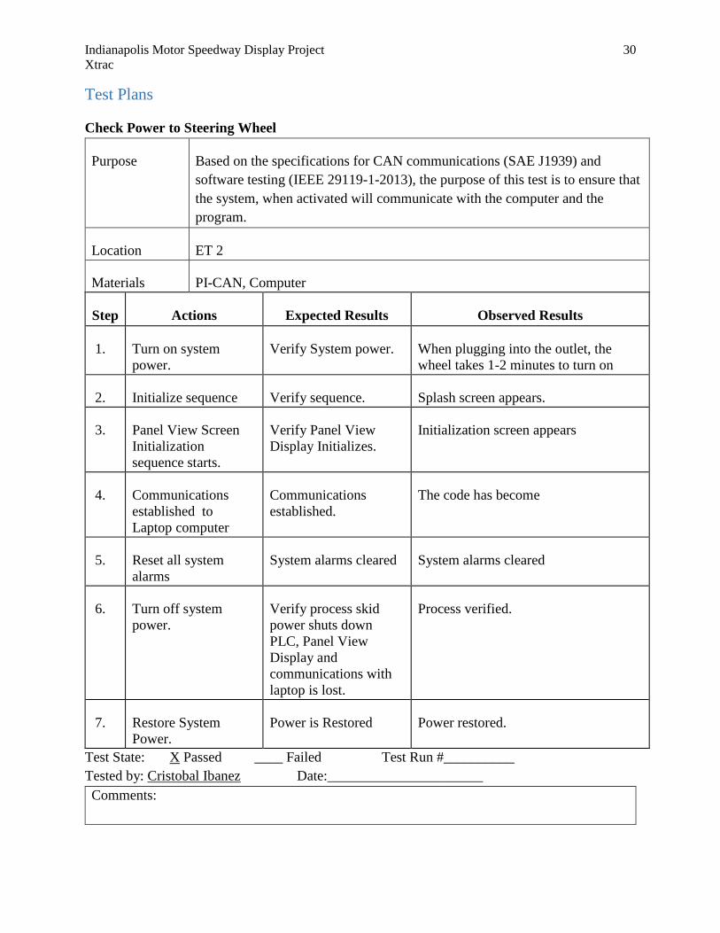
Check Power to Steering Wheel
Purpose Based on the specifications for CAN communications (SAE J1939) and
software testing (IEEE 29119-1-2013), the purpose of this test is to ensure that
the system, when activated will communicate with the computer and the
program.
Location ET 2
Materials PI-CAN, Computer
Step Actions Expected Results Observed Results
1. Turn on system
power.
Verify System power. When plugging into the outlet, the
wheel takes 1-2 minutes to turn on
2. Initialize sequence Verify sequence. Splash screen appears.
3. Panel View Screen
Initialization
sequence starts.
Verify Panel View
Display Initializes.
Initialization screen appears
4. Communications
established to
Laptop computer
Communications
established.
The code has become
5. Reset all system
alarms
System alarms cleared System alarms cleared
6. Turn off system
power.
Verify process skid
power shuts down
PLC, Panel View
Display and
communications with
laptop is lost.
Process verified.
7. Restore System
Power.
Power is Restored Power restored.
Test State: X Passed ____ Failed Test Run #__________
Tested by: Cristobal Ibanez Date:______________________
Comments:

Indianapolis Motor Speedway Display Project 31
Xtrac
Checking Button
Purpose Based on the specifications for CAN communications (SAE J1939), software
testing (IEEE 29119-1-2013) and PLC involvement (IEC 1131-3), the purpose
of this test is to ensure that the steering wheel and the control box send signals
back and forth to one another.
Location ET 2
Materials Control Box, PI-CAN, Computer
Step Actions Expected Results Observed Results
1. Press Button 1 Shift gear down The screen shows that the simulation
has shifted down
2. Press Button 2 Acceleration The acceleration box shows the
numbers increasing the longer the
button is held
3. Press Button 3 Shift LED from RPM
to gear display
The display changes when button is
pressed
4. Press Button 4 Shift Gear Up The screen shows that the simulation
has shifted up
5. Press Button 5 Stop Confirmed stop. Must test for
integration
6. Press Button 6 Change display from
KPH to MPH
Display changes from KPH to MPH
and vice versa
7. Press Paddle 1 Shift gear down The screen shows that the simulation
has shifted down
8. Press Paddle 2 Shift Gear Up The screen shows that the simulation
has shifted up
Test State: X Passed ____ Failed Test Run #__________
Tested by: Cristobal Ibanez Date:______________________
Comments:

Indianapolis Motor Speedway Display Project 32
Xtrac
Checking Actuator
Purpose Following IEC 1131-3, this test is to ensure that the actuator will extend and
retract correctly and separately from the transmission, thereby influencing the
movement of the ratchet and shift up and down the gears.
Location ET 220
Materials Gearbox, computer, Ethernet cable, micro820 Allen Bradley programmable
controls
Step Actions Expected Results Observed Results
1. When “start”
activates
The system turns on There is a click in the PLC that
indicates the system has turned on.
2. When “stop”
activates
The system turns off There is a click in the PLC that
indicates the system has turned on.
Testing the other wires reveals that the
act was successful
3. When “shift up”
activates
Actuator extends
before returning to
home
The actuator extends then returns to
home. However, when the shift
up/down activates whilst the actuator is
returning to home, the process is
interrupted and continues with the new
process
4. When “shift down”
activates
Actuator retract before
returning to home
The actuator extends then returns to
home. However, when the shift
up/down activates whilst the actuator is
returning to home, the process is
interrupted and continues with the new
process
Test State: X Passed ____ Failed Test Run #__________
Tested by: Charleston Shi and Cristobal Ibanez Date:______________________
Comments:
Indianapolis Motor Speedway Display Project 33
Xtrac
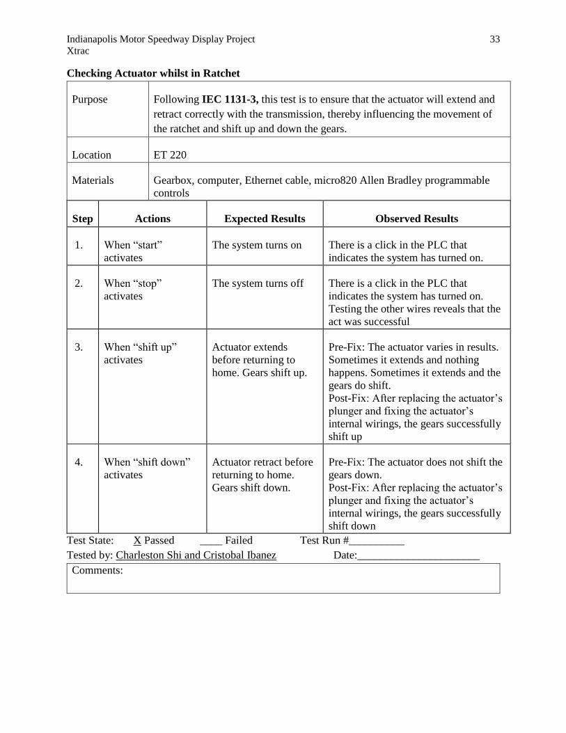
Checking Actuator whilst in Ratchet
Purpose Following IEC 1131-3, this test is to ensure that the actuator will extend and
retract correctly with the transmission, thereby influencing the movement of
the ratchet and shift up and down the gears.
Location ET 220
Materials Gearbox, computer, Ethernet cable, micro820 Allen Bradley programmable
controls
Step Actions Expected Results Observed Results
1. When “start”
activates
The system turns on There is a click in the PLC that
indicates the system has turned on.
2. When “stop”
activates
The system turns off There is a click in the PLC that
indicates the system has turned on.
Testing the other wires reveals that the
act was successful
3. When “shift up”
activates
Actuator extends
before returning to
home. Gears shift up.
Pre-Fix: The actuator varies in results.
Sometimes it extends and nothing
happens. Sometimes it extends and the
gears do shift.
Post-Fix: After replacing the actuator’s
plunger and fixing the actuator’s
internal wirings, the gears successfully
shift up
4. When “shift down”
activates
Actuator retract before
returning to home.
Gears shift down.
Pre-Fix: The actuator does not shift the
gears down.
Post-Fix: After replacing the actuator’s
plunger and fixing the actuator’s
internal wirings, the gears successfully
shift down
Test State: X Passed ____ Failed Test Run #__________
Tested by: Charleston Shi and Cristobal Ibanez Date:______________________
Comments:

Indianapolis Motor Speedway Display Project 34
Xtrac
Checking Shift Up/Down While Motor is implemented
Purpose Following IEC 1131-3, this test is to ensure that the actuator will extend and
retract correctly with the transmission when the motor has been implemented,
thereby influencing the movement of the ratchet and shift up and down the
gears.
Location ET 220
Materials Gearbox, computer, Ethernet cable, micro820 Allen Bradley programmable
controls
Step Actions Expected Results Observed Results
1. When “start”
activates
The system turns on There is a click in the PLC that
indicates the system has turned on.
2. When “stop”
activates
The system turns off There is a click in the PLC that
indicates the system has turned on.
Testing the other wires reveals that the
act was successful
3. Motor load test The motor spins when
wires are connected
The motor spins while wires are
connected
4. Motor
implementation
The motor spins the
gears
The motor spins the gears
5. When “shift up”
activates
Actuator extends
before returning to
home. Gears shift up.
Pre-Fix: The actuator varies in results.
Sometimes it extends and nothing
happens. Sometimes it extends and the
gears do shift.
Post-Fix: After replacing the actuator’s
plunger and fixing the actuator’s
internal wirings, the gears successfully
shift up
6. When “shift down”
activates
Actuator retract before
returning to home.
Gears shift down.
Pre-Fix: The actuator does not shift the
gears down.
Post-Fix: After replacing the actuator’s
plunger and fixing the actuator’s
internal wirings, the gears successfully
shift down
Test State: X Passed ____ Failed Test Run #__________
Tested by: Charleston Shi and Cristobal Ibanez Date:______________________
Indianapolis Motor Speedway Display Project 35
Xtrac
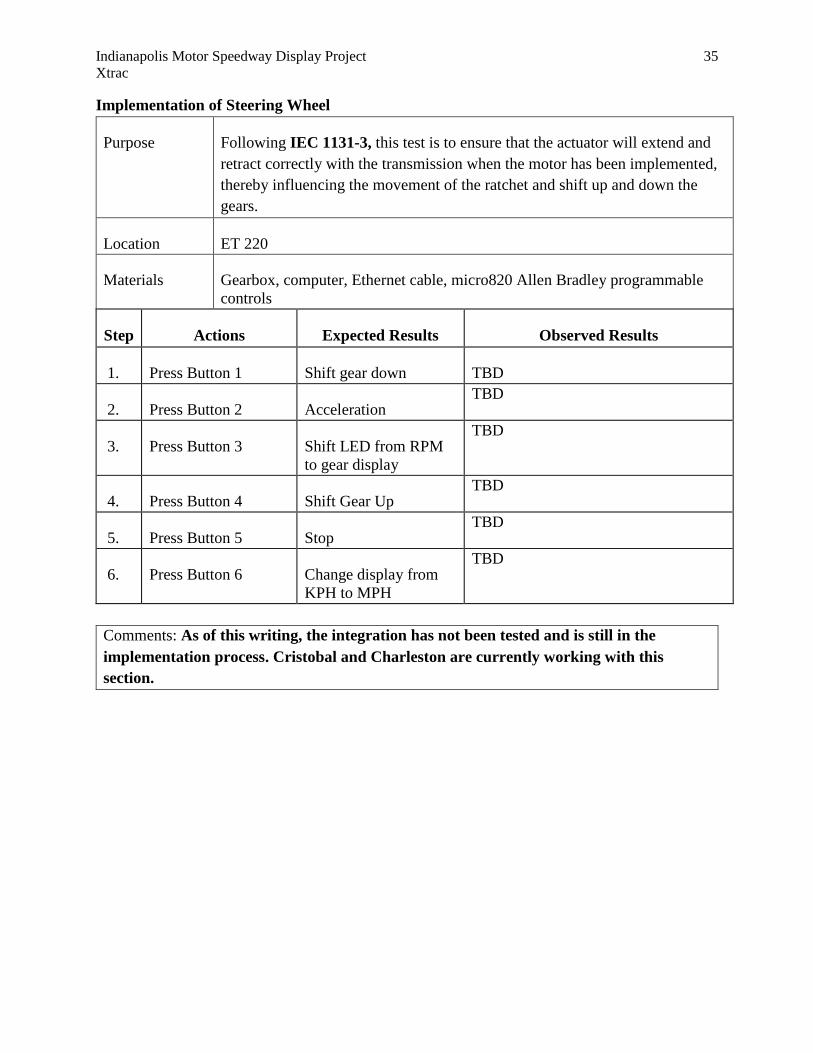
Implementation of Steering Wheel
Purpose Following IEC 1131-3, this test is to ensure that the actuator will extend and
retract correctly with the transmission when the motor has been implemented,
thereby influencing the movement of the ratchet and shift up and down the
gears.
Location ET 220
Materials Gearbox, computer, Ethernet cable, micro820 Allen Bradley programmable
controls
Step Actions Expected Results Observed Results
1. Press Button 1 Shift gear down TBD
2. Press Button 2 Acceleration TBD
3. Press Button 3 Shift LED from RPM
to gear display
TBD
4. Press Button 4 Shift Gear Up TBD
5. Press Button 5 Stop TBD
6. Press Button 6 Change display from
KPH to MPH
TBD
Comments: As of this writing, the integration has not been tested and is still in the
implementation process. Cristobal and Charleston are currently working with this
section.

Indianapolis Motor Speedway Display Project 36
Xtrac
Conclusion
Through his project IMS is allowing engineering students the opportunity to gain experience and
be involved with the racing community as well as have experience in a high-profile project. As
such, the purpose of this to interface a racecar steering wheel with engine transmission box in
order to send signals back and forth upon activation.
Recommendations
In the event that the interface will not be complete by December 20, 2019, the necessary actions need to
be taken are as such per the current and/or future specifications of the sponsor:
The interface is the communication of the steering wheel to the Micro 820 Controller. All
controls will have to be transferred to the steering wheel and must be able to directly
communicate with the current program downloaded to the controller

Indianapolis Motor Speedway Display Project 37
Xtrac
References
Table 6 – Standards and Related Documents
Title Source Comment
IEEE 15026-1-2014 https://standard
s.ieee.org/stand
ard/15026-1-
2014.html
Potential code case structures
and contents
IEC 1131-3 http://isa.uniov
i.es/genia/engli
sh/publicacion
es/IEC%20%2
01131-3.pdf
Possible PLC involvement in
the process
ISO/IEC/IEEE 29119-1-2013 http://www.sof
twaretestingsta
ndard.org/
Software testing
ISA Standards https://www.is
a.org/standards
-publications/
Recognized automation
standards
NFPA 79-2018 https://www.nf
pa.org/codes-
and-
standards/all-
codes-and-
standards/list-
of-codes-and-
standards/detai
l?code=79
provides safeguards for
industrial machinery to protect
operators, equipment,
facilities, and work-in-progress
from fire and electrical hazards
29D-032985-U www.cosworth
.com
Wheel Specifications and
diagrams