echolife hg8240&hg8245&hg8247 gpon terminal quick startmanuals.zedt.eu/echolife...
TRANSCRIPT

Quick Start
EchoLife HG8240&HG8245&HG8247 GPON Terminal

Huawei Proprietary and ConfidentialCopyright © Huawei Technologies Co., Ltd.
EchoLife HG8240&HG8245&HG8247 GPON Terminal
V100R002C00&C01
Quick Start
Issue 04
Date 2011-02-15
Part Number 31504933

Huawei Technologies Co., Ltd. provides customers with comprehensive technical support and service. For any assistance, please contact our local office or company headquarters.
Huawei Technologies Co., Ltd.
Address:
Huawei Industrial BaseBantian, LonggangShenzhen 518129People's Republic of China
Website: http://www.huawei.com
Email: [email protected]
Copyright © Huawei Technologies Co., Ltd. 2011. All rights reserved.No part of this document may be reproduced or transmitted in any form or by any means without prior written consent of Huawei Technologies Co., Ltd.
Trademarks and Permissions
and other Huawei trademarks are the property of Huawei Technologies Co., Ltd.All other trademarks and trade names mentioned in this document are the property of their respective holders.
NoticeThe information in this document is subject to change without notice. Every effort has been made in the preparation of this document to ensure accuracy of the contents, but the statements, information, and recommendations in this document do not constitute a warranty of any kind, express or implied.
Huawei Proprietary and ConfidentialCopyright © Huawei Technologies Co., Ltd.

Precautions
Basic Requirements
� Keep the device dry during storage, transportation, and running of the device.
� Prevent the device from colliding with other objects during storage, transportation, and running of the device.
� Install the device in strict compliance with the vendor requirements.
� Do not uninstall the device without permission. Contact the specified service center when a fault occurs on the device.
� No enterprise or personnel should modify the structure, and security and performance design of the device without authorization.
� Abide by the local laws and regulations and respect the legal rights of others when using the device.
Environmental Requirements
� Install the device in a well-ventilated place that is not directly exposed to sunlight.
� Keep the device clean.
� Keep the device away from water sources or wet places.
� Do not place any objects on the device to prevent the device from being damaged by heat or weight of the object placed on the device.
� Leave a space of at least 10 cm around the device for heat dissipation.
� Keep the device away from heat sources or bare fire sources, such as electrical heaters and candles.
� Keep the device away from the electrical appliances with strong magnetic fields or strong electric fields, such as microwave ovens, refrigerators, and mobile phones.
Instructions for Cleaning
� Before cleaning the device, stop running it, switch off the power, and remove all cables, including the power cable, optical fibers, and network cables, from the device.
� Do not use cleaning fluid or spray-on detergent to clean the case of the device. Use a soft cloth instead.
For safety purposes, before operating the device, read the safety precautions carefully.
1

Precautions
Instruction for Use � Use the accessories delivered with the device, or use those recommended by the vendor, such as the power adapter and battery.
� The power supply voltage of the device must meet the requirements on the input voltage of the device.
� Keep the power plug clean and dry to avoid electric shocks or any other hazard.
� Dry your hands before removing or inserting cables.
� Stop the device and switch off the power before removing or inserting cables.
� Switch off the power and remove all cables, including the power cable, optical fibers, and network cables, from the device during stormy days.
� Switch off the power and remove the power plug if the device is shut down for a long term.
� Keep the device free of contact with water or other liquid. If such an accident occurs, switch off the power immediately and remove all cables, including the power cable, optical fibers, and network cables, from the device. Contact the specified service center in case of a device failure.
� Do not stamp, pull, drag, or excessively bend the cables because they may get damaged, thus leading to a device failure.
� Do not use cables that are damaged or aged.
� Do not look directly into the optical port on the device without eye protection as the infrared may injure your eyes.
� In case of any abnormalities, such as smoke, abnormal sound, or odor, immediately stop the device, switch off the power, and remove all cables, including the power cable, optical fibers, and network cables, from the device. Contact the specified service center in case of a device failure.
� Prevent foreign objects such as metal objects from dropping into the device through the heat dissipation holes.
� Prevent the outer case of the device from being scratched as the paint that falls into the device may cause a short circuit. In addition, it can cause an allergic reaction to human body.
� Keep the device out of the reach of children as the components or accessories may be swallowed.
Instructions for Environmental Protection � Dispose of the obsolete device and batteries to the specified recycle place.
� Abide by the local laws and regulations to handle the packaging materials, run-out batteries and obsolete device.
2

3
Introduction
Product Name Appearance
HG8240
HG8245
HG8247
The appearance of GPON terminals HG8240, HG8245 and HG8247 is as follows:
The HG8240, HG8245 and HG8247 have slightly differ in appearance, ports, LEDs, and technical specifications. For details, see "Connecting Cables", "Description of LEDs", and "Technical Specifications"
The figures shown in this document may differ from the actual GPON Terminal, but the difference does not affect the functions of the GPON Terminal.
4
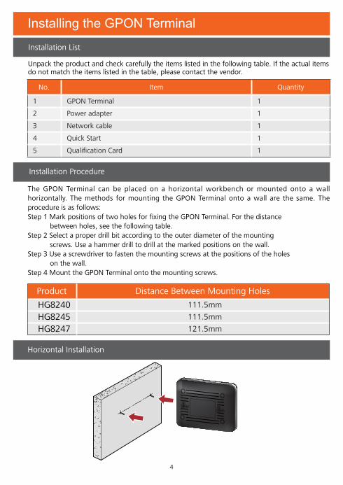
Installing the GPON Terminal
Installation List
Product Distance Between Mounting Holes
HG8240 111.5mm
HG8245 111.5mm
HG8247 121.5mm
No. Item Quantity
1 GPON Terminal 1
2 Power adapter 1
3 Network cable 1
4 Quick Start 1
5 Qualification Card 1
Horizontal Installation
Unpack the product and check carefully the items listed in the following table. If the actual items do not match the items listed in the table, please contact the vendor.
Installation Procedure
The GPON Terminal can be placed on a horizontal workbench or mounted onto a wall horizontally. The methods for mounting the GPON Terminal onto a wall are the same. The procedure is as follows:Step 1 Mark positions of two holes for fixing the GPON Terminal. For the distance between holes, see the following table.Step 2 Select a proper drill bit according to the outer diameter of the mounting screws. Use a hammer drill to drill at the marked positions on the wall.Step 3 Use a screwdriver to fasten the mounting screws at the positions of the holes on the wall.Step 4 Mount the GPON Terminal onto the mounting screws.
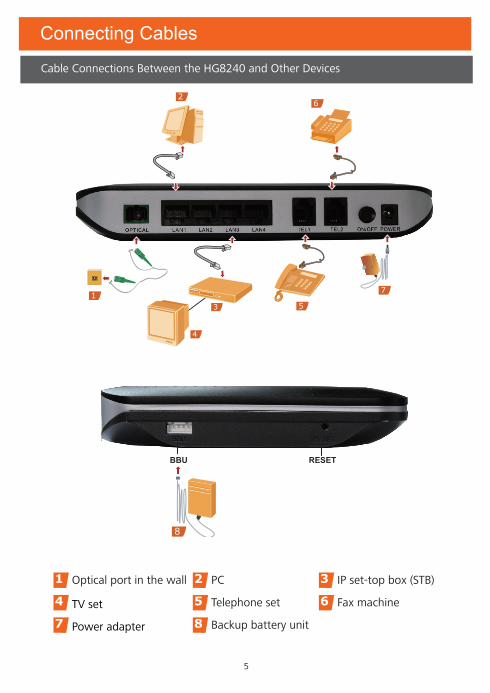
Connecting Cables
5
Cable Connections Between the HG8240 and Other Devices
4
3
6
5
7
2
1
1 Optical port in the wall 2 PC 3 IP set-top box (STB)
4 TV set 5 Telephone set 6 Fax machine
7 Power adapter 8 Backup battery unit
BBU RESET
8

6
Cable Connections Between the HG8245 and Other Devices
Connecting Cables
5
4
73
6
8
2
1
BBU WLAN WPS RESETUSB
109
1 Optical port in the wall 2 PC 3 Wi-Fi terminal
4 IP set-top box (STB) 5 TV set 6 Telephone set
7 Fax machine 8 Power adapter 9 Backup battery unit
10 USB storage device

7
Connecting Cables
Cable Connections Between the HG8247 and Other Devices
1 Optical port in the wall 2 PC 3 Wi-Fi terminal
4 IP set-top box (STB) 5 TV set 6 Telephone set
7 Fax machine 8 Power adapter 9 Backup battery unit
10 USB storage device
BBU WLAN WPS RESETUSB
109
5
4
73
6
8
2
1
5

8
Step 1 Use an optical fiber to connect the OPTICAL port on the GPON Terminal to the optical port in the wall.
Step 2 Use a coaxial cable to connect the CATV port to the TV set or STB.Step 3 Use a network cable to connect the LAN port to the Ethernet port of the PC or IP STB.Step 4 Use a telephone cable to connect the TEL port to the telephone set or fax machine.Step 5 Use a power cable to connect the POWER port to the power adapter or backup battery unit.
Step 6 Use a USB data cable to connect the USB port to the USB storage device.Step 7 Press the ON/OFF power button.Step 8 Press the WLAN switch to enable the Wi-Fi access function. By default, this function is enabled.Step 9 Press the WPS switch to enable the WPS encryption function.
Connecting CablesRefer to the preceding cable connections of each product and select the following corresponding steps to connect the GPON terminal.
The optical connector connected to the optical port is SC/APC, and the type of the optical connector connected to the optical port in the wall is determined according to actual conditions.
The preceding figure considers connecting of the power adapter as an example. When the backup battery is used, it is recommended that you use a power monitoring cable to connect the BBU port to the monitoring port of the backup battery. In this way, the function of monitoring the backup battery on the GPON terminal is available. For details on how to use the backup battery, see the backup battery usage guide.
Before enabling the WPS encryption function of the GPON Terminal by pressing the WPS switch, make sure that the function is configured on the system software
beforehand.
9
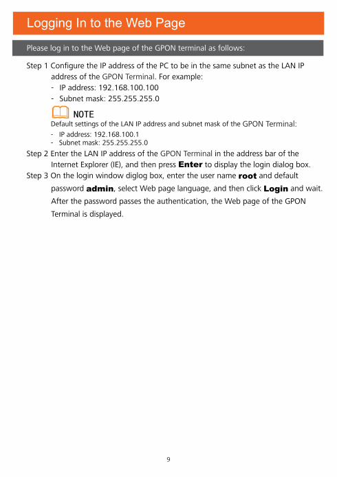
Step 1 Configure the IP address of the PC to be in the same subnet as the LAN IP address of the GPON Terminal. For example: - IP address: 192.168.100.100 - Subnet mask: 255.255.255.0
Step 2 Enter the LAN IP address of the GPON Terminal in the address bar of the Internet Explorer (IE), and then press Enter to display the login dialog box.Step 3 On the login window diglog box, enter the user name root and default
password admin, select Web page language, and then click Login and wait.
After the password passes the authentication, the Web page of the GPON
Terminal is displayed.
Logging In to the Web Page
Please log in to the Web page of the GPON terminal as follows:
Default settings of the LAN IP address and subnet mask of the GPON Terminal:- IP address: 192.168.100.1- Subnet mask: 255.255.255.0

Description of LEDs
LEDs of the HG8245
10
LEDs of the HG8240

Description of LEDs
LEDs of the HG8247
11

12
Description of LEDs
LED Status Description
CATVOn The CATV function is enabled and CATV signals are
received.
Off The CATV function is disabled or CATV signals are not received.
WPS
On The WPS function is enabled.
Blinking At least one Wi-Fi terminal is accessing the system.
Off The WPS function is disabled.
WLAN
On The WLAN function is enabled.
Blinking Data is being transmitted.
Off The WLAN function is disabled..
USB
On The USB port is connected and is working in the host mode, but no data is transmitted.
Fast blinking
(Twice per second)Data is being transmitted.
Off The system is not powered on or the USB port is not connected.
TEL1 - TEL2
On The connection between the TEL port and the voice server has been set up.
Fast blinking
(Twice per second)The voice service of the TEL port is established and is in the off-hook or ringing state.
Slow blinking
(Once two seconds)The voice service of the TEL port is registering.
Off The connection between the TEL port and the voice server is not set up.
LAN1 - LAN4
On Ethernet connection is normal.
Blinking Data is being transmitted through the Ethernet port.
Off Ethernet connection is not set up.
LOS/PON See Table 2.
POWER
Green The GPON Terminal is powered on.
Orange The backup battery is supplying power.
Off The GPON Terminal is powered off.
Read the following description of LEDs by referring to the preceding figures of LEDs.
Table 1 LED status indications 1
In the preceding table, if the LED status is marked "Blinking" but the frequency is not specified, it indicates that the blinking frequency of the LED is determined by the data traffic transmitted.

13
Description of LEDsPON and LOS are GPON LEDs. The status of PON and LOS reflects the connection between GPON terminal and the optical line terminal (OLT). The following table describes the status of the PON and LOS LEDs.
Table 2 LED status indications 2
No.Status
DescriptionPON LOS
1 Off Off The ONT is disabled by the OLT.
2 Fast blinking
(Twice per second)
Off The ONT tries to create a connection to the OLT.
3 On Off A connection is created between the ONT and the OLT.
4 Off Slow blinking
(Once two seconds)
The receive optical power of the ONT is lower than the receiver sensitivity.
5 Fast blinking
(Twice per second)
Fast blinking
(Twice per second)
The OLT detects that the device is a rogue ONT.
When the LEDs are in the states as described in No. 5, that is, the OLT detects that the device is a rogue ONT, rectify the fault in time and replace the rogue ONT.

14
FAQsThe POWER LED is off.
� Check whether the ON/OFF button on the rear panel is pressed. � Check whether the power adapter matches the GPON Terminal. � Check whether the power connection is correct.
The LOS LED is blinking. � When the LOS LED blinks slowly, check whether the pigtail fiber is connected normally and whether the optical connector is contaminated.
� When the LOS LED blinks quickly, check whether the GPON Terminal transmits optical signals normally.
The PON LED is off. � Check whether the optical fiber is properly connected to the OPTICAL port.
� The GPON Terminal fails to register with the OLT. Contact the service provider for help.
The CATV LED is off. � Contact the service provider to confirm that you have subscribed to the CATV function or received the CATV signal..
The LAN LED is off. � Check whether the network cable delivered with the device is used. � Check whether the network cable is connected properly. � Check whether the LED of the network adapter is on. � Check whether the network adapter works normally.
The TEL LED is off. � Check whether a voice user is configured and enabled.
The WPS LED is off. � Check whether the WPS service is started.
The WLAN LED is off. � Check whether the WLAN service is started.
The USB LED is off. � Check whether the connection of the USB device is correct.
The phone does not ring when it receives a call, but the communication is normal when the phone is in the offhook state.
� The ONT provides a maximum ringing current voltage of 60 V AC. Please check that the ringing current voltage of the phone does not exceed 60 V AC; otherwise, change another phone.
How to reset the GPON Terminal? � Press the RESET button by using a sharp-ended object and then release the button. Press the button to reset the device; press and hold the button (longer than 10s) to restore the device to the default settings and reset the device. If the LED is off and then on again, it indicates that the system is reset successfully.

15
Item HG8240 HG8245 HG8247Dimensions
(L x W x H)
195 mm x 155 mm
x 34 mm
195 mm x 174 mm
x 34 mm
268 mm x 213 mm
x 34 mm
Weight (including the
power adapter)About 500 g About 550 g About 800 g
Power supply 11 - 14 V DC, 1 A 11 - 14 V DC, 2 A 11 - 14V DC, 2 A
Power
adapter input
100 - 240 V AC
50 - 60 Hz
100 - 240 V AC
50 - 60 Hz
100 - 240 V AC
50 - 60 Hzmaximum
consumption12 W 17 W 19.5 W
Working
temperature0 - 40 oC 0 - 40 oC 0 - 40 oC
Working humidity5 - 95 % (non-
condensing)
5 - 95 % (non-
condensing)
5 - 95 % (non-
condensing)
Technical Specifications

User Information
Personal or Company Full Name:__________________________________________________
Address/Postal Code:____________________________________________________________
Telephone Number:______________________________________________________________
Email:_________________________________________________________________________
Product Type:___________________________________________________________________
Product Serial Number:___________________________________________________________
Purchase Date:_________________________________________________________________
Invoice Number:________________________________________________________________
Dealer's Name:_________________________________________________________________
Dealer's Address:________________________________________________________________
Dealer's Telephone:______________________________________________________________
Warranty Card
Thank you for choosing Huawei Technologies Co., Ltd. – a leading telecom solution provider. To get better services, please read this warranty card carefully, fill in the required information, and preserve this card in good condition.
Preserve well. No reissue.
Dealer's Seal:

Limited Warranty
Huawei Technologies Co., Ltd.
Address: Huawei Industrial BaseBantian, LonggangShenzhen 518129People's Republic of ChinaWebsite: http://www.huawei.com
Subject to the exclusions contained below, Huawei Technologies Co., Ltd. (hereinafter referred to as Huawei) warrants its access terminals (“Products”) to be free from defects in materials and workmanship under normal consumer usage for one year from the date of purchase of the product ("Warranty period"). During the warranty period, a Huawei authorized service partner shall remedy defects in materials and workmanship free of charge.Special Notice:(1) The warranty card shall be applicable only after being stamped by the dealer.(2) The warranty card must be preserved in good condition and free of any scratch or alteration.(3) To claim such service for defects that are not included in the following exclusion terms, the warranty card and the invoice that records the product serial number shall be presented to a Huawei authorized service partner.Exclusions:
In any of the following cases, the warranty card becomes unenforceable or inapplicable without prior notice:(1) The defects are caused by improper handling in transportation and assembly.(2) The defects are caused by the fact that the product is dismantled or altered by anyone that is not from a Huawei authorized service partner.(3) The defects are caused by the fact that the product is used in a harsh environment that is not suitable for the operation of the product.(4) The defects are caused by any force majeure including but not limited to fire, earthquake, lightning and tsunami.(5) The defects are caused by the fact that the product is used or handled improperly, roughly or not as instructed in the applicable User Guide.(6) The normal wear and tear, including but not limited to the normal wear and tear of the shell and the power module, shall not be covered by the limited warranty.(7) The warranty card is altered or illegible, or the product serial number recorded on the warranty card is inconsistent with the actual one imprinted or labeled on the product.
In any case that is not covered by this limited warranty or should the warranty expire, Huawei shall charge for the service(s) claimed for the products if the product is still remediable. Huawei preserves the right for interpretation of this limited warranty.

Huawei Technologies Co., Ltd.Huawei Industrial Base
Bantian, LonggangShenzhen 518129
People's Republic of China
www.huawei.com