echosonix u71-u73 ultrasonic transmitter gi1034 - sor … · integral terminal block diagram ........
TRANSCRIPT

Form 1034 (05.13) ©SOR Inc. 1/40
echOsonix is a non-contact, ultrasonic level sensing device. It provides several product-handling functions in one device.
Isolated 4-20 mA reversible analog output scaled over the range entered by the user Modbus digital communications Switch - Two (model U71 integral mount) or four (model U73 remote mount) programmable Form C SPDT relays Switch function choices of energize on high or low level, fail-safe or disabled Switch settings fully independent of level transmitter range and other relays All values entered in engineering units Push-button setup, no ranging or calibration required Field selected application type from liquid, slurry or solid Simulate mode to test parameter settings and relay/analog outputs Automated false echo handling Diagnostics - Features to aid installation/setup and provide testing and diagnostic functions
General Instructions
Registered Quality System to ISO 9001
Design and specifications are subject to change
without notice.
For latest revision, go to www.sorinc.com
NOTE: If you suspect that a product is
defective, contact the factory or the
SOR® Representative in your area for
a return authorization number (RMA).
This product should only be installed
by trained and competent personnel.
Table of ContentsSafety .............................................3 Quick Start Installation Guide .................4Mounting the Transducer ......................6Focusing Cone and Flange Assembly ...... 10Electronic Housing Installation ............. 11Transducer Cable Installation ............... 12Integral Electronics Wiring .................. 12Wiring Diagram ............................... 14Integral Terminal Block Diagram ........... 16Remote Terminal Block Diagram ........... 16Modbus Wiring Diagram ..................... 17Modbus Network .............................. 18Keypad Interface .............................. 20LCD Display .................................... 21Field Programming ........................... 22User Defi ned Values .......................... 23Menu Structure ................................ 26Dimensions .................................... 28Product Specifi cations ....................... 33Troubleshooting ............................... 34
U71-U73 Ultrasonic Transmitter
ensing device. It provides several
U73
U71

2/40 Form 1034 (05.13) ©SOR Inc.
These instructions provide information for Mounting, Process and Electrical connections and Field Programming of the echOsonix transmitter.
The echOsonix incorporates a transducer for sending and receiving an ultrasonic signal and an electronics processing package. The ultrasonic signal is very powerful and may cause hearing damage - refer to the safety instructions on page 3. The electronics package is either mounted on top of the transducer or in a remote location connected by a shielded cable.Prior to installation, review these instructions entirely. Transducer mounting location is critical to proper operation. Most settings can be programmed prior to installation.
The PC boards are serialized to each unit and should not be removed except by the factory. Removing the PC board will render the warranty null and void.
Form 1034 (05.13) ©SOR Inc. 3/40
Safety
Electrical Safety
The echOsonix is an electrically powered transmitter. Common electrical safety procedures must be followed when working with this equipment. All wiring should be per local and national standards. Do not remove the enclosure cover unless the area is known to be non-hazardous. Do not handle circuit boards when energized.
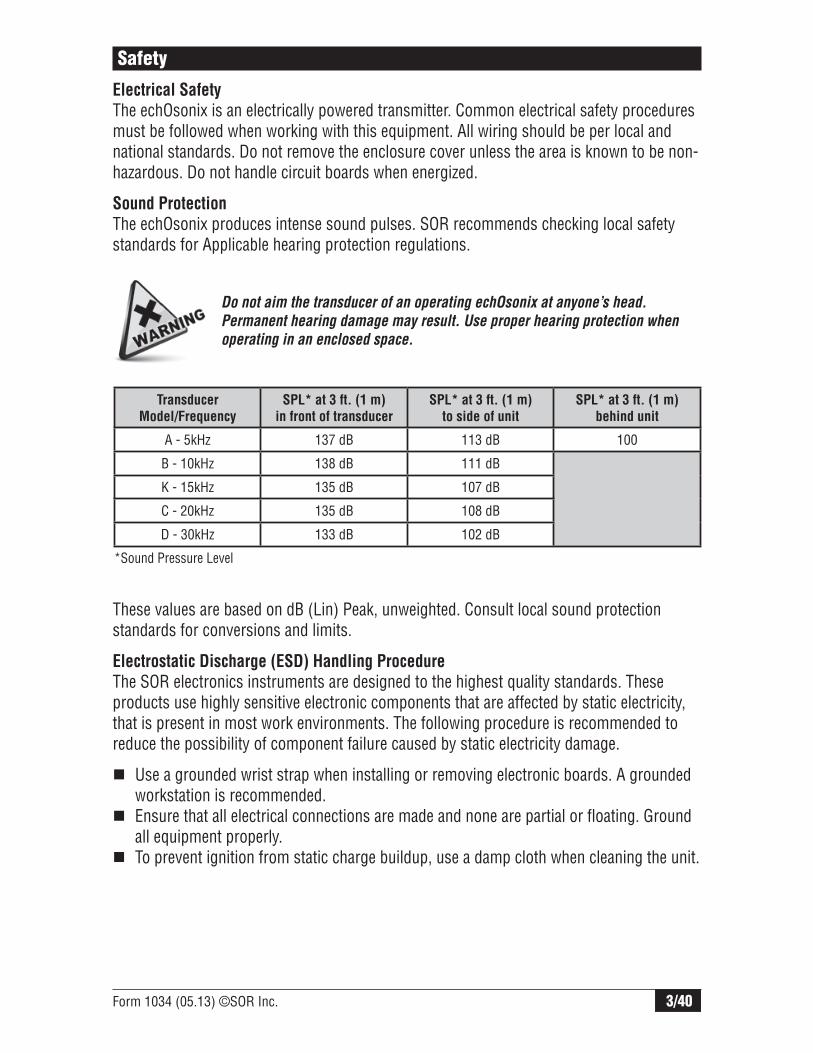
Sound Protection
The echOsonix produces intense sound pulses. SOR recommends checking local safety standards for Applicable hearing protection regulations.
Do not aim the transducer of an operating echOsonix at anyone’s head.
Permanent hearing damage may result. Use proper hearing protection when
operating in an enclosed space.
These values are based on dB (Lin) Peak, unweighted. Consult local sound protection standards for conversions and limits.
Electrostatic Discharge (ESD) Handling Procedure
The SOR electronics instruments are designed to the highest quality standards. These products use highly sensitive electronic components that are affected by static electricity, that is present in most work environments. The following procedure is recommended to reduce the possibility of component failure caused by static electricity damage.
Use a grounded wrist strap when installing or removing electronic boards. A grounded workstation is recommended.
Ensure that all electrical connections are made and none are partial or floating. Ground all equipment properly.
To prevent ignition from static charge buildup, use a damp cloth when cleaning the unit.
*Sound Pressure Level
Transducer
Model/Frequency
SPL* at 3 ft. (1 m)
in front of transducer
SPL* at 3 ft. (1 m)
to side of unit
SPL* at 3 ft. (1 m)
behind unit
A - 5kHz 137 dB 113 dB 100
B - 10kHz 138 dB 111 dB
K - 15kHz 135 dB 107 dB
C - 20kHz 135 dB 108 dB
D - 30kHz 133 dB 102 dB

4/40 Form 1034 (05.13) ©SOR Inc.
Quick Start Installation Guide
This guide is intended to be a quick reference only. Please refer to each section of this form for details on installation, wiring, set-up and operation. Contact the factory or your local representative if you have any questions or concerns.
Install the transducer away from obstructions. Do not mount in the center of domed or conical roof tanks. See page 6 for minimum mounting distance from tank walls.
Wire the unit according to local and national safety codes. Power and signal wiring must be run as a minimum. Refer to pages 11-17 for more wiring details.
NOTE: Proper earth grounding of electronics is critical!
Flanged Mounting
Avoid mounting end of transducer assembly inside standpipe.
Use a shorter standoff so end of transducer assembly
is inside vessel, or...
Extend standpipe into the vessel and cut the
end at a 45o angle.
Use a threaded coupling directly on top of the
vessel, or...
Extend standpipe into the vessel and cut the
end at a 45o angle.
See page 9 for standoff details.
Inlet Pipe
Test
GND
+DC
GND
Neut
ral
Activ
e
RL1N
O
RL1C
RL1N
C
RL2N
O
RL2C
RL2N
C
GND
l+ l- ICOM
BA
22-27 VDCPower Supply
100-126 VAC or200-230 VACPower Supply
PLC/DCSor Indicator
PLC/DCSPowered Card
++- - 250250
And/Or Or
Threaded Mounting
Avoid mounting end of transducer assembly inside standpipe.

Form 1034 (05.13) ©SOR Inc. 5/40
Black
Red
White
Blue
Green
Yellow
Black
***RedWhiteBlueGreenYellow
Black
***RedWhiteBlueGreenYellow
Wire Shield (Drain)
CableInsulation
White & Black
If supplied, cut this wire – do not use
Black
***RedWhite BlueGreenYellow
Wire Shield (Drain)
CableInsulation
White & Black
To splice remote transducer cables, follow the diagram below. See page 12 for details.
*** Brown or Red/Black, depending on cable. * Yellow or Orange
***
*
Relay Point
Highest Level
High Level
100%
Relay Point
Lowest Level
Low Level
0%
Blanking (No detection)
High Level
(20 mA)
L1 Level
(Any relay)
L2 Level
(Any relay)
Lo Level
(4mA)
Calculate the level distances for the vessel. These will be entered when programming the unit. All values are measured from the transducer face down to the desired level. See pages 23-24 for details of each value.
NOTE: All values are measured
from the transducer face down.
Hi Level will be a smaller number
than Lo Level.
Program the basic parameters in the setup menu. Press CAL to access the menu. Enter the Application Type, Hi Level, Lo Level and relay settings using the values calculated in the above step. See pages 26 and 27 for menu structure and description.
NOTE: Push-button interface is the
same for integral and remote units.
To change number values fast,
hold down the arrow key and
press CAL.
This guide is intended to be a quick reference only. Please refer to each section of this form for details on installation, wiring, set up and operation. Contact the factory or your local representative if you have any questions or concerns.
Return to normal operation Enter menus, change menu selection, accept changes
Change numeric values and move between menu options
{
Distance12.34 ft.DistanceDistance
12.34 ft.12.34 ft.calrun
NOTE: Do not exceed loft of cable added or taken off
6/40 Form 1034 (05.13) ©SOR Inc.
Mounting the Transducer
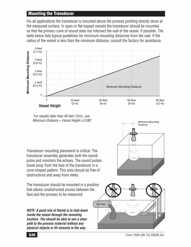
For all applications the transducer is mounted above the process pointing directly down at the measured surface. In open or flat topped vessels the transducer should be mounted so that the primary cone of sound does not intersect the wall of the vessel, if possible. The table below lists typical guidelines for minimum mounting distances from the wall. If the radius of the vessel is less than the minimum distance, consult the factory for assistance.
Vessel Height
For vessels taller than 40 feet (12m), use: Minimum Distance = Vessel Height x 0.087
0
1 foot (0.3 m)
2 feet (0.6 m)
3 feet (0.9 m)
4 feet (1.2 m)
10 feet (3 m)
20 feet (6 m)
30 feet (9 m)
40 feet (12 m)
0
Minimum Mounting Distance
Minimum Mounting Distance
Transducer mounting placement is critical. The transducer assembly generates both the sound pulse and monitors the echoes. The sound pulses travel away from the face of the transducer in a cone-shaped pattern. This area should be free of obstructions and away from inlets.
The transducer should be mounted in a position that allows unobstructed access between the face and the process to be measured.
Inlet Pipe
NOTE: A good rule of thumb is to look down
inside the vessel through the mounting
location. You should be able to see a clear
path to the process material without any
physical objects or fi ll streams in the way.

Form 1034 (05.13) ©SOR Inc. 7/40
Alternative Mounting
echOsonix units may be mounted inside a stilling well or bridle to avoid excessive obstructions or turbulence in the process. Follow the guidelines shown below for the stilling well or bridle, then see page 38 for special instructions.
Bridle
Stilling Well
Inlet Pipe
Min. 2”
Min. 4” Diameter
Min. 4” Diameter
MinimumHoles
echOsonix units are designed to read solids materials and ignore the angle of repose. The angle of repose is the angle between horizontal and the side of the pile of material. For processes where the angle of repose is greater than 45 degrees, the echOsonix may require some special tuning or setup. Contact the factory for these situations.
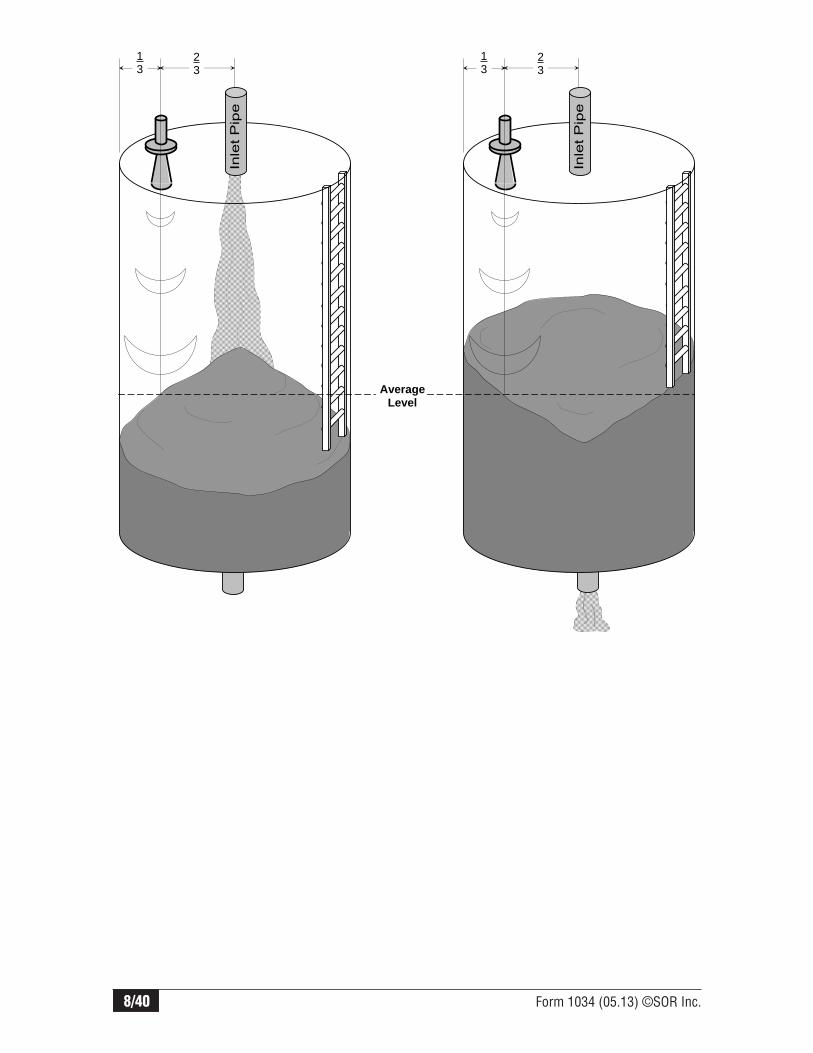
For solids installations, the echOsonix should be mounted in a vertical position according to the diagram below. Do not “aim” the transducer to the angle of repose, this is not necessary. Mount the transducer 1/3 of the distance from the vessel wall to the vessel centerline, away from any internal obstructions.
For vessels that fill and discharge from the center, this mounting location will provide a good average level measurement. As solids pile up they form a cone, and as they discharge they form a conical pit. By measuring the level at the 1/3 radius position shown, an average level is obtained for both situations. For vessels that do not fill and/or discharge from the center, a mounting location should be chosen that will provide the best possible average level.
8/40 Form 1034 (05.13) ©SOR Inc.
13
23
13
23
Average Level

Form 1034 (05.13) ©SOR Inc. 9/40
echOsonix transducers may be mounted using a threaded connection or a flanged connection. Some units require flange mounting. There are two options for thread mounting which are detailed below. In all cases, the transducer should be installed in a stable, permanent mounting fixture.
Focusing Cones
All units are supplied with some form of focusing cone to be mounted on the transmitting end of the transducer. These cones should always be installed according to the instructions in this manual. If the mounting method inhibits this cone, the mounting should be modified to account for it. The cones are vital to proper performance and should not be modified or removed.
Thread Mounting
Short-range transducers (30, 20 and 15kHz) may be supplied with a 3” NPT mounting thread. All remote transducers are also supplied with a 1” NPT/BSP cable nipple that can be used for either conduit connection or mounting.
Flange Mounting
When mounting a unit with a flange, we recommend using non-metallic bolts. The mounting bolts should be hand-tight only. Do not over-tighten the bolts, this can affect performance of the echOsonix transducer.
Most flange mounts use a standpipe. It is important to follow the guidelines below for standpipe design. Methods are shown in order of preference - Method 1 preferred, etc.
Method 1 Method 2 Method 3
End of transducer assembly extends past
end of standpipe
End of standpipe is cut at a 45°
angle, transducer is inside pipe End of transducer is
inside standpipe.
Ratio of H / D = 1 or less D is Minimum 4”
H
D

10/40 Form 1034 (05.13) ©SOR Inc.
Focusing Cone and Flange Assembly
Units supplied with focusing cones and flanges are shipped disassembled. Follow the directions below to assemble these units prior to installation.
Transducer (Sensor)
MountingFlange
Focusing Cone
Locking Ring
For 10kHz (BBP, RBP, BEP), screw locking ring
down tight onto top of focusing coneOr
For 5kHz (BAP, RAP) locking ring is not moveable, screw transducer down until locking
ring is tight onto top of focusing cone
Mount transducer
into flange assembly.
Thread focusing cone into mounting flange.
NOTE: All threaded connections
should be sealed with either Tefl on
tape or a thread sealer that is
compatible with Polypropylene.
Install mounting flange / focusing
cone assembly into process.
NOTE:
Mount fl ange
as shown; small
threaded fl ange
MUST be pointing up.
Form 1034 (05.13) ©SOR Inc. 11/40
Electronic Housing Installation
For integral units, the electronic housing assembly is permanently attached to the transducer and mounted at the same time. This design unit is not considered here.
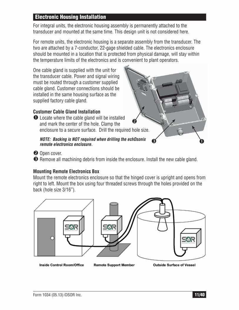
For remote units, the electronic housing is a separate assembly from the transducer. The two are attached by a 7-conductor, 22-gage shielded cable. The electronics enclosure should be mounted in a location that is protected from physical damage, will stay within the temperature limits of the electronics and is convenient to plant operators.
One cable gland is supplied with the unit for the transducer cable. Power and signal wiring must be routed through a customer supplied cable gland. Customer connections should be installed in the same housing surface as the supplied factory cable gland.
Customer Cable Gland Installation
Locate where the cable gland will be installed and mark the center of the hole. Clamp the enclosure to a secure surface. Drill the required hole size.
NOTE: Backing is NOT required when drilling the echOsonix remote electronics enclosure.
Open cover.Remove all machining debris from inside the enclosure. Install the new cable gland.
Mounting Remote Electronics Box
Mount the remote electronics enclosure so that the hinged cover is upright and opens from right to left. Mount the box using four threaded screws through the holes provided on the back (hole size 3/16”).
12/40 Form 1034 (05.13) ©SOR Inc.
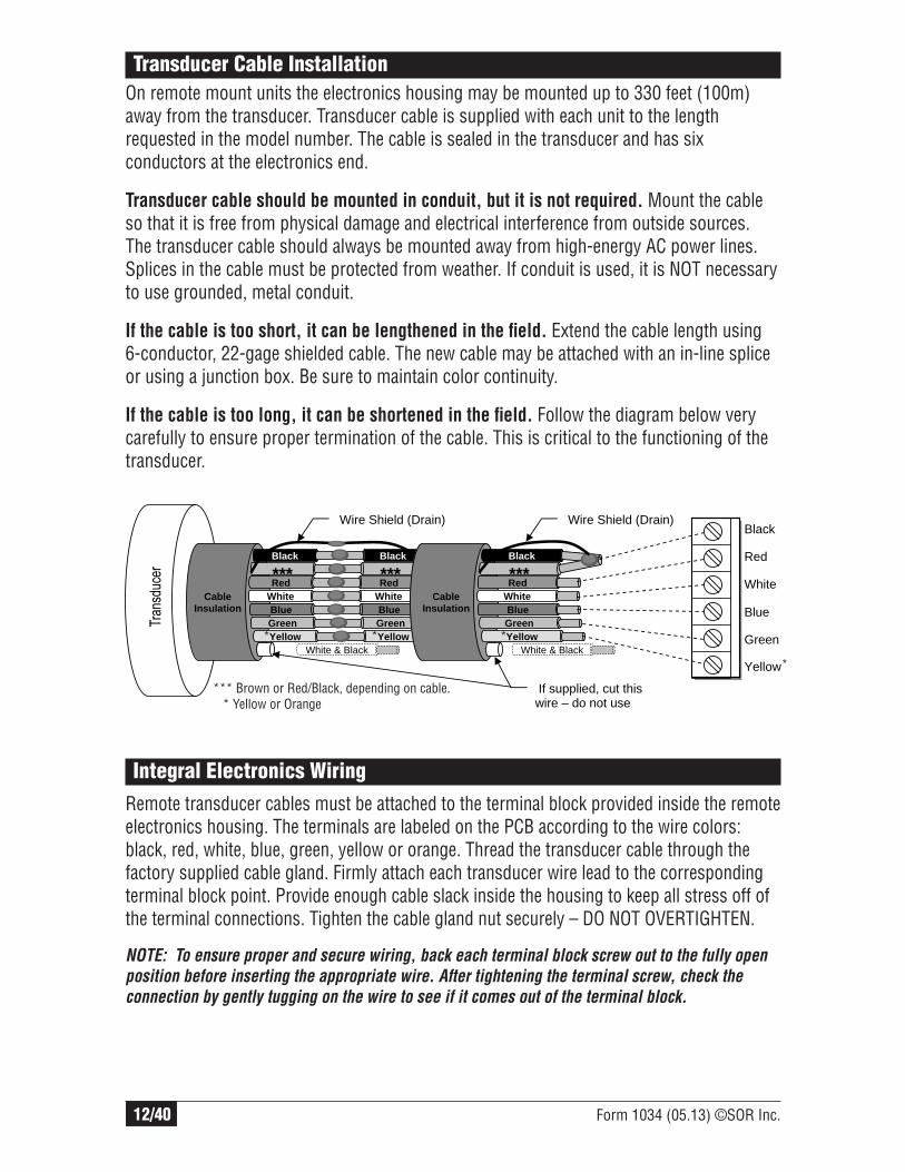
Transducer Cable Installation
On remote mount units the electronics housing may be mounted up to 330 feet (100m) away from the transducer. Transducer cable is supplied with each unit to the length requested in the model number. The cable is sealed in the transducer and has six conductors at the electronics end.
Transducer cable should be mounted in conduit, but it is not required. Mount the cable so that it is free from physical damage and electrical interference from outside sources. The transducer cable should always be mounted away from high-energy AC power lines. Splices in the cable must be protected from weather. If conduit is used, it is NOT necessary to use grounded, metal conduit.
If the cable is too short, it can be lengthened in the fi eld. Extend the cable length using 6-conductor, 22-gage shielded cable. The new cable may be attached with an in-line splice or using a junction box. Be sure to maintain color continuity.
If the cable is too long, it can be shortened in the fi eld. Follow the diagram below very carefully to ensure proper termination of the cable. This is critical to the functioning of the transducer.
Black
Red
White
Blue
Green
Yellow
Black
***RedWhiteBlueGreenYellow
Black
***RedWhiteBlueGreenYellow
Wire Shield (Drain)
CableInsulation
White & Black
If supplied, cut this wire – do not use
Black
***RedWhite BlueGreenYellow
Wire Shield (Drain)
CableInsulation
White & Black
*** Brown or Red/Black, depending on cable. * Yellow or Orange
***
*
Integral Electronics Wiring
Remote transducer cables must be attached to the terminal block provided inside the remote electronics housing. The terminals are labeled on the PCB according to the wire colors: black, red, white, blue, green, yellow or orange. Thread the transducer cable through the factory supplied cable gland. Firmly attach each transducer wire lead to the corresponding terminal block point. Provide enough cable slack inside the housing to keep all stress off of the terminal connections. Tighten the cable gland nut securely – DO NOT OVERTIGHTEN.
NOTE: To ensure proper and secure wiring, back each terminal block screw out to the fully open
position before inserting the appropriate wire. After tightening the terminal screw, check the
connection by gently tugging on the wire to see if it comes out of the terminal block.
Form 1034 (05.13) ©SOR Inc. 13/40
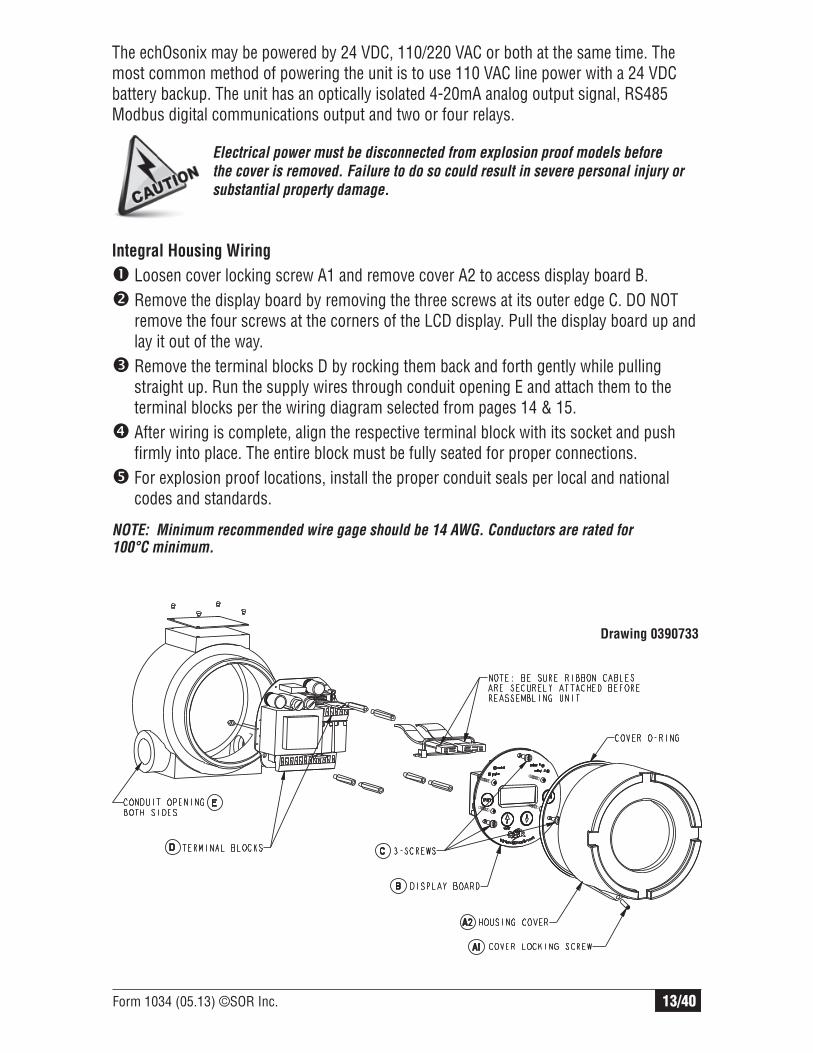
Integral Housing Wiring
Loosen cover locking screw A1 and remove cover A2 to access display board B.Remove the display board by removing the three screws at its outer edge C. DO NOT
remove the four screws at the corners of the LCD display. Pull the display board up and lay it out of the way.
Remove the terminal blocks D by rocking them back and forth gently while pulling straight up. Run the supply wires through conduit opening E and attach them to the terminal blocks per the wiring diagram selected from pages 14 & 15.
After wiring is complete, align the respective terminal block with its socket and push firmly into place. The entire block must be fully seated for proper connections.
For explosion proof locations, install the proper conduit seals per local and national codes and standards.
Electrical power must be disconnected from explosion proof models before
the cover is removed. Failure to do so could result in severe personal injury or
substantial property damage.
Drawing 0390733
NOTE: Minimum recommended wire gage should be 14 AWG. Conductors are rated for 100°C minimum.
The echOsonix may be powered by 24 VDC, 110/220 VAC or both at the same time. The most common method of powering the unit is to use 110 VAC line power with a 24 VDC battery backup. The unit has an optically isolated 4-20mA analog output signal, RS485 Modbus digital communications output and two or four relays.

14/40 Form 1034 (05.13) ©SOR Inc.
Wiring Diagram
All echOsonix units may be powered by either AC or DC external supplies. The analog 4-20mA circuit may either be powered from the echOsonix internally or by a user-supplied external DC power supply. The wiring diagrams below specify the wiring options for either 3-wire DC, 4-wire DC or AC external power supplies.
The analog 4-20mA circuit is a self-powered, optically isolated negative side current control loop. The current is actually controlled between the “I COM” and “I-” terminals of the unit. The “I+” terminal is the internally regulated voltage source for self powering the current loop. The loop is approximately +17V above the output common “I COM”.
Terminal Connections for DC Supply
a) 3-Wire DC – 4-20mA driven from Common User Supply (RL to +DC)
b) 3-Wire DC – 4-20mA driven from Common User Supply (RL to GND)
c) 4-Wire DC – 4-20mA driven from Internal Isolated Supply (I+)

Form 1034 (05.13) ©SOR Inc. 15/40
Terminal Connections for AC Supply
d) 4-20mA driven from User’s External DC Supply (RL to Pos.)
e) 4-20mA driven from User’s External DC Supply (RL to Neg.)
f) 4-20mA driven from Internal Isolated Supply (I+)
16/40 Form 1034 (05.13) ©SOR Inc.
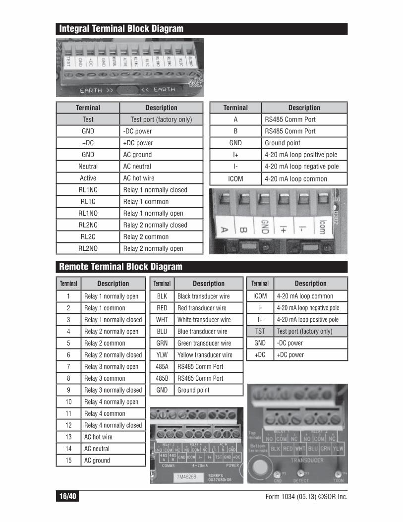
Integral Terminal Block Diagram
Terminal Description
Test Test port (factory only)
GND -DC power
+DC +DC power
GND AC ground
Neutral AC neutral
Active AC hot wire
RL1NC Relay 1 normally closed
RL1C Relay 1 common
RL1NO Relay 1 normally open
RL2NC Relay 2 normally closed
RL2C Relay 2 common
RL2NO Relay 2 normally open
Terminal Description
A RS485 Comm Port
B RS485 Comm Port
GND Ground point
I+ 4-20 mA loop positive pole
I- 4-20 mA loop negative pole
ICOM 4-20 mA loop common
Terminal Description
1 Relay 1 normally open
2 Relay 1 common
3 Relay 1 normally closed
4 Relay 2 normally open
5 Relay 2 common
6 Relay 2 normally closed
7 Relay 3 normally open
8 Relay 3 common
9 Relay 3 normally closed
10 Relay 4 normally open
11 Relay 4 common
12 Relay 4 normally closed
13 AC hot wire
14 AC neutral
15 AC ground
Remote Terminal Block Diagram
Terminal Description
BLK Black transducer wire
RED Red transducer wire
WHT White transducer wire
BLU Blue transducer wire
GRN Green transducer wire
YLW Yellow transducer wire
485A RS485 Comm Port
485B RS485 Comm Port
GND Ground point
Terminal Description
ICOM 4-20 mA loop common
I- 4-20 mA loop negative pole
I+ 4-20 mA loop positive pole
TST Test port (factory only)
GND -DC power
+DC +DC power
Form 1034 (05.13) ©SOR Inc. 17/40
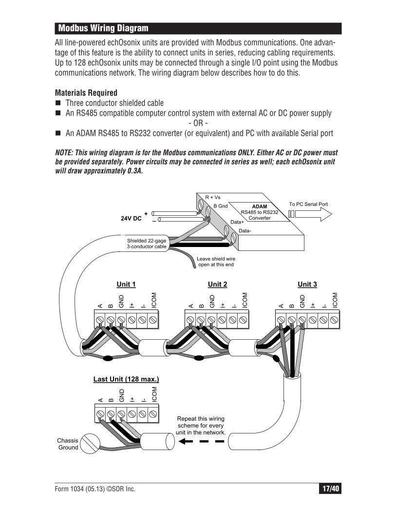
Modbus Wiring Diagram
All line-powered echOsonix units are provided with Modbus communications. One advan-tage of this feature is the ability to connect units in series, reducing cabling requirements. Up to 128 echOsonix units may be connected through a single I/O point using the Modbus communications network. The wiring diagram below describes how to do this.
Materials Required
Three conductor shielded cable An RS485 compatible computer control system with external AC or DC power supply
- OR - An ADAM RS485 to RS232 converter (or equivalent) and PC with available Serial port
NOTE: This wiring diagram is for the Modbus communications ONLY. Either AC or DC power must
be provided separately. Power circuits may be connected in series as well; each echOsonix unit
will draw approximately 0.3A.
A B GN
D
I+ I- ICO
M
24V DC
A B GN
D
I+ I- ICO
M
A B GN
D
I+ I- ICO
M
A B GN
D
I+ I- ICO
M
Leave shield wire open at this end
Unit 1 Unit 2 Unit 3
Last Unit (128 max.)
Repeat this wiring scheme for every
unit in the network.
ChassisGround
Shielded 22-gage 3-conductor cable
ADAM RS485 to RS232
Converter
R + Vs
B Gnd
Data+
Data-
+
–
To PC Serial Port

18/40 Form 1034 (05.13) ©SOR Inc.
Modbus Network
Each echOsonix has a communications address that must be unique. The Modbus protocol uses this address to identify each unit. The default address “1” must be changed before connecting more than one unit to the network. This can be done either through the on-board menus or the Modbus interface. Follow one of the procedures below to address each unit before connecting them all to the network.
On-Board Menu Procedure
Provide power to the unit. At the normal operations screen on the LCD, press CAL once. The screen will change to
“UnLock: 0”. Use the up arrow to enter “195” for the unlock code. Press CAL once. The screen will
change to “Setup”. Press the up arrow twice to change the screen to “Tracking”. Press CAL once. Press CAL until the screen says “CommAdds: 1”. This is the communications address value. Press the up arrow to enter the unique communications address for this unit – range is 1 to 255.
NOTE: Do not use addresses 3 or 6.
Press RUN to save the communications address. Repeat this procedure for every unit in the network, making sure each one has a unique address.
Modbus Interface Procedure
Connect one unit to both the power supply and the Modbus network per the prior wiring diagram. Set up the controlling computer software to write to the Comms Address parameter per
the chart on page 19. Write a unique communications address to this unit. This address must be between “2” and “255”. Connect one more unit to both the power supply and the Modbus network. Repeat steps 3 and 4 until all units have been connected to the network and given a
unique address.
Modbus Address Defi nitions
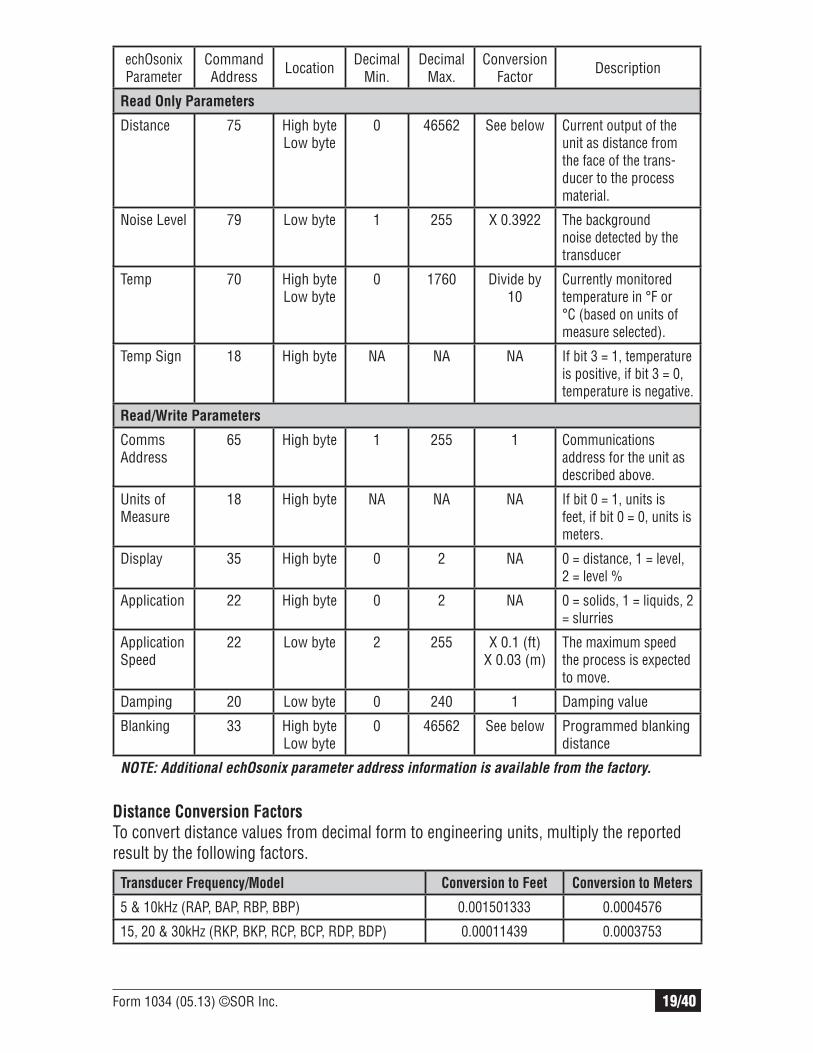
Many users will want to connect echOsonix units to their pre-existing Modbus compatible control system. To do this, they must know what information is available over the Modbus network, where it is located, and how to manipulate it. The chart below defines the most commonly used addresses on the echOsonix unit. It is not the intention of this documentto educate users on the fundamentals of Modbus protocols. More information can be found at www.modbus.org.
Form 1034 (05.13) ©SOR Inc. 19/40
echOsonix Parameter
Command Address Location Decimal
Min.Decimal
Max.Conversion
Factor Description
Read Only Parameters
Distance 75 High byteLow byte
0 46562 See below Current output of the unit as distance from the face of the trans-ducer to the process material.
Noise Level 79 Low byte 1 255 X 0.3922 The background noise detected by the transducer
Temp 70 High byteLow byte
0 1760 Divide by 10
Currently monitored temperature in °F or °C (based on units of measure selected).
Temp Sign 18 High byte NA NA NA If bit 3 = 1, temperature is positive, if bit 3 = 0, temperature is negative.
Read/Write Parameters
Comms Address
65 High byte 1 255 1 Communications address for the unit as described above.
Units of Measure
18 High byte NA NA NA If bit 0 = 1, units is feet, if bit 0 = 0, units is meters.
Display 35 High byte 0 2 NA 0 = distance, 1 = level, 2 = level %
Application 22 High byte 0 2 NA 0 = solids, 1 = liquids, 2 = slurries
Application Speed
22 Low byte 2 255 X 0.1 (ft)X 0.03 (m)
The maximum speed the process is expected to move.
Damping 20 Low byte 0 240 1 Damping value
Blanking 33 High byteLow byte
0 46562 See below Programmed blanking distance
NOTE: Additional echOsonix parameter address information is available from the factory.
Distance Conversion Factors
To convert distance values from decimal form to engineering units, multiply the reported result by the following factors.
Transducer Frequency/Model Conversion to Feet Conversion to Meters
5 & 10kHz (RAP, BAP, RBP, BBP) 0.001501333 0.0004576
15, 20 & 30kHz (RKP, BKP, RCP, BCP, RDP, BDP) 0.00011439 0.0003753

20/40 Form 1034 (05.13) ©SOR Inc.
Keypad Interface
The echOsonix requires a minimal amount of parameter setup. The units, display, process type and range must be set for each application. All other parameters should be set as required or desired. The large picture below shows the setup interface for an integral unit. The remote unit controls are shown in the inset. The next section shows the menu choices as well as a brief description of each feature.
NOTE: When changing numerical values, hold down the arrow but-
ton and push the CAL button to make the numbers change faster.
But be careful – if you let go of the arrow while pushing the CAL
button the display will move to the next programming step.
LCD Display
RUN button- used to exit menus and return to normal operation
CAL button - used to enter menus and select/save menu choices
UP and DOWN arrow buttons - used to move between menu options and change values
Pulse indicator light
Echo Indicator LED– Readable Echo Received
Relay Indicator LEDs – Status of Relays (LED on, relay is energized)
Remote Unit Controls

Form 1034 (05.13) ©SOR Inc. 21/40
LevelLevel26.83f26.83f
LevelLevel28,70f28,70f
EngUnitsEngUnitsFeetFeet
Gn 9%Gn 9%26.80ft26.80ft
LCD Display
Normal Operation
In normal operation the top line of the LCD shows the Material Display Mode selected in the menu setup - Space or Material %. The second line displays the actual level status. The unit can always be returned to normal operation by pressing the RUN button.
Normal Operation screen - display type on top line, level reading on bottom line.
When the decimal changes to a comma, the U71/U73 has lost echo and is trying to recover it.
Programming Mode
In programming mode the top line of the display indicates what feature is being pro-grammed. The bottom line shows the current choice for that feature. Move from feature to feature using the arrow keys and press CAL to select and change that feature.
Programming feature shown on top line, user choices/values shown on bottom line.
Troubleshooting Mode
When the unit is in normal operation, troubleshooting information is displayed by pressing the up arrow key. The top line of the LCD changes to the troubleshooting information, the lower line continues to display the level reading.
Troubleshooting data displayed on top line, level reading on bottom line.
Every U71/U73 comes with 2-line 16-character LCD display. This serves as a display of process level and an interface for setting up the unit. There are three LCD display modes: normal operation, troubleshooting and programming.
INDICATOR MEANING
. (Decimal) Normal operation, (Comma) Recover mode – echo lost: (Colon) Hold Mode – false echo found outside of window

22/40 Form 1034 (05.13) ©SOR Inc.
“CAL” Button
The CAL button is used to enter the menus and select menu options to change. Press CAL from normal operation to enter the password screen. Enter the password using the arrow keys (factory default is 0) and press CAL to go to the menus. When the proper menu item is selected using the arrow buttons, press CAL again to access that feature and make changes.
Field Programming
The U71/U73 menus are accessible through the four-button keypad on the display board. Information is displayed on the 2-line LCD, with the program feature shown on the top line and the current setting displayed on the bottom line. All button functions are consistent for all models and menus.
Units in Hazardous Locations – Prior to programming, make sure that the
work area is declassifi ed before removing the explosion proof cover to
program the unit. Failure to do so could result in severe personal injury or
substantial property damage.
The and arrow buttons are used to change user values and move between menu items. When changing numeric values, hold the arrow button down and the values will change faster the longer it is held. When the button is released and pressed again the numbers will change at a slower rate.
cal
run“RUN” Button
The RUN button returns the unit to normal operation mode. This button will exit the menus at any point, saving the current selected options and entering normal operation using all changes made in the menus.

Form 1034 (05.13) ©SOR Inc. 23/40
User Defi ned Values
Several user-defined values must be entered for each application. The figure belowillustrates these values and how they should be determined. It is important to remember that all distance values are measured from the sensor down.
Blanking Every ultrasonic transmitter has a dead zone near the transducer where it cannot measure level. In the U71/U73 this is called the Blanking. The blanking is normally auto-matic but may be set to a specific value if required for the application. If the user defined blanking is shorter than the distance required by the automatic blanking, the U71/U73 defaults to the automatic value.
4 or 20mA Endpoints The range of the U71/U73 is determined by setting the distance from the transducer to the 4 and 20mA endpoints. An output of 20-4mA can be obtained by set-ting the 4mA point at the top and the 20mA point at the bottom. These values are entered in engineering units (feet or meters).
Distance The Echo Elimination* feature requires a Distance value to be entered. This is the maximum distance to eliminate false echoes. When used, this value should be set slightly higher than the low level of the process so that it does not eliminate the bottom of the range. *USE THIS FEATURE ONLY WHEN REQUIRED!
Empty Distance (EmpyDst) The empty distance defines the farthest echo the U71/U73 will accept. This eliminates the possibility of reading a secondary echo that appears to be below the bottom of the vessel. The Emptdst value should be set slightly farther than the end of the measured range so it will not blank out the bottom of the process.

24/40 Form 1034 (05.13) ©SOR Inc.
Blanking (No detection)
Hi Level(20 mA)*
L1 Level**(Any Relay)
L2 Level**(Any Relay)
Lo Level(4 mA)*
Hi Level(100%)
Relay PointHighest Level
Relay PointLowest Level
Low Level0%
* The 4-20 mA output can be reversed to 20-4 mA in the Trim menu. See page 23.
**L1 and L2 relay settings can be set outside of the range of the Hi Level and Lo Level.
Form 1034 (05.13) ©SOR Inc. 25/40
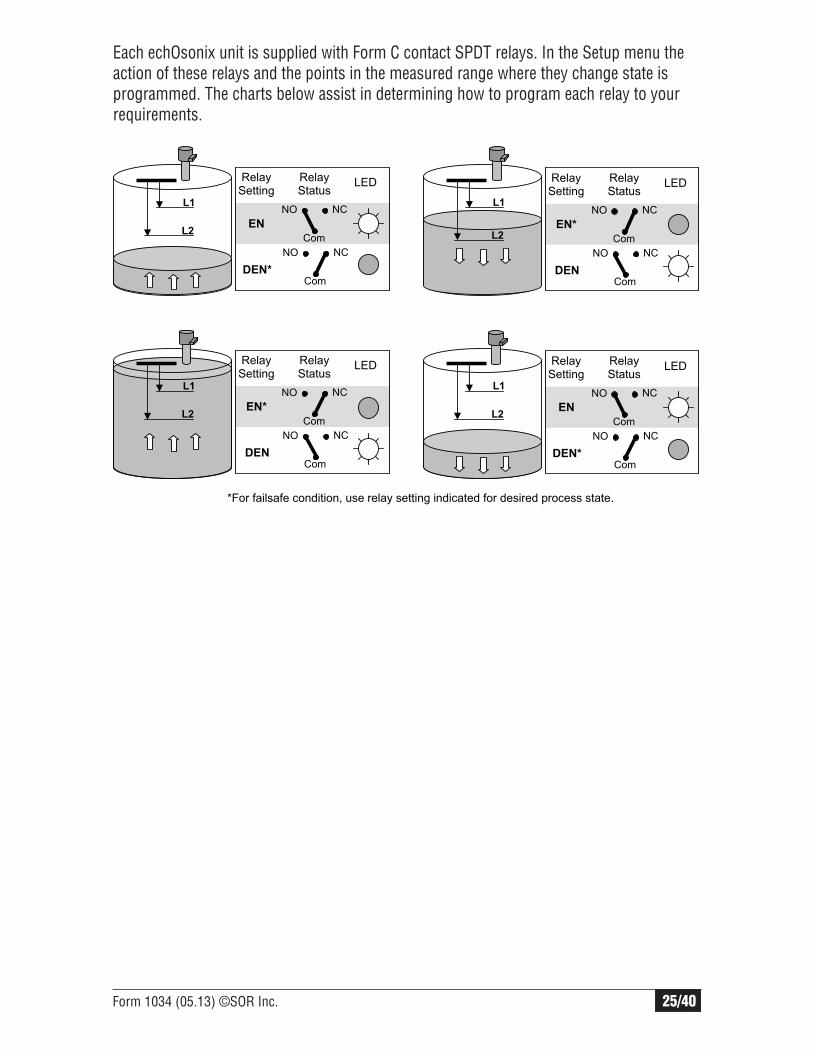
Each echOsonix unit is supplied with Form C contact SPDT relays. In the Setup menu the action of these relays and the points in the measured range where they change state is programmed. The charts below assist in determining how to program each relay to your requirements.
L1
L2
L1
L2
L1
L2
L1
L2
Relay Setting
EN
DEN*
RelayStatus
LED
NO
Com
NC
NO
Com
NC
Relay Setting
EN*
DEN
RelayStatus
LED
NO
Com
NC
NO
Com
NC
Relay Setting
EN*
DEN
RelayStatus
LED
NO
Com
NC
NO
Com
NC
Relay Setting
EN
DEN*
RelayStatus
LED
NO
Com
NC
NO
Com
NC
*For failsafe condition, use relay setting indicated for desired process state.

26/40 Form 1034 (05.13) ©SOR Inc.
Menu Structure
The echOsonix is programmed and tested through two menus. A third menu is used to alter the automated features - consult the factory for access to this menu.
Level L1 is the switching point closest to the transducer. L2 is the farthest switching point. Relay action and levels L1/L2 are repeated for each relay in the unit.
DistanceLevelLevel %
SolidsLiquidsSlurries
Yes/No (Yes to change)
Set to the maximum speed the process is expected to move. This setting is critical to allow the unit to keep proper track of the media. The units are feet per minute (f/M) or meters per minute (m/M).
Blanking is the dead zone in front of the transducer that the unit ignores. This value should not be decreased from default values, but may be increased as required.
4.00 mA20.00 mAHold Last Value>20.00 mA<4.00 mA
Set the rate for damping turbulent processes. The display reading and analog output are damped by an average of the last X readings, where X is the damping value entered here.
Lower numbers provide faster reaction, higher numbers provide more damping.
OffFail SafeEn Den
Setup
Setup Menu
User-defined values are entered in the setup menu. The transmitter is programmed for the specific application it will be used in, including process levels.
Normal Operation
Trim Menu
Tracking Menu(Consult the factory)
Setup Menu
Normal Operation
Unlock
Setup
continued next column
Setup (continued)
A password may be entered here to protect the unit from unauthorized reprogramming. Consult the factory if the password is lost. Factory default is “Ø”.
CAL
CAL
UnitsCAL
FeetMeters
Display ModeCAL
Application TypeCAL
Speed (display only)CAL
CAL
Damping XCAL
Lo Level X.XX ftCAL
Hi Level X.XX ftCAL
Blanking X.XX ftCAL
Fail OutputCAL
Relay Number 1 ActionCAL
Relay 1 L1 X.XX ftCAL
Relay 1 L2 X.XX ftCAL
Password XXXCALSpeed Adjust?

Form 1034 (05.13) ©SOR Inc. 27/40
Trim Menu
Many applications require the instrument to be fine-tuned for the existing conditions. The Trim menu allows adjustment of output signals, process condition parameters and signal processing for difficult conditions.
Trim
Yes / No (Yes to adjust)
Yes / No (Yes to adjust)
Actual output value of the 4 mA and 20 mA can be adjusted as required. A current meter will be necessary to monitor actual output during adjustment.
4-20 mA20-4 mA
X.XX ft.
Exercises all outputs as though the distances shown were from the transducer down to process. The 4-20 mA output and all relays will respond according to the distance measurement shown as adjusted by the keypad arrow.
X.XX ft.
This is used to account for an installation offset. The display and outputs will be offset by this value from -0.65 ft. to 23.83 ft. (-0.2m to 7.26m).
1.0000
If the vapor in a process has a different speed of sound than air, correct for it here. 1.0000 = air, enter other values as percent of air (95% = 0.9500).
Gain Trim Yes / No
Gain (GN) XX.X%
Gain Step (GS) XX.X%
Distance (DS) X.XX ft.
These values alter how the echOsonix processes signal echoes. See page 34-37 for troubleshooting details.
Forces the unit into FAIL mode when the level reaches the blanking distance.
Thld X.XX
When you believe this parameter is necessary, use the following formula: Velocity = Actual Measured Distance echOsonix Distance Reading
Fail Blank Yes / NoCAL
CAL
CAL
4 mA AdjustCAL
20 mA AdjustCAL
AnalogCAL
Simulate Yes / NoCAL
Offset Yes / No
Velocity Yes / NoCAL

28/40 Form 1034 (05.13) ©SOR Inc.
Dimensions
Remote Electronics
30 kHz TransducerFC Option
Dimensions are for reference only. Contact the factory for certified drawings for a particular model number.
Linear = mm/inches
Drawing 0390625
Remote Electronics
20 kHz TransducerFC Option
Linear = mm/inches
Drawing 0390626

Form 1034 (05.13) ©SOR Inc. 29/40
Remote Electronics
15 kHz Transducer
Linear = mm/inches
Drawing 0390647
Remote Electronics
10 kHz Transducer
Linear = mm/inches
Drawing 0390627

30/40 Form 1034 (05.13) ©SOR Inc.
Remote Electronics
5 kHz Transducer
Linear = mm/inches
Drawing 0390628
Form 1034 (05.13) ©SOR Inc. 31/40
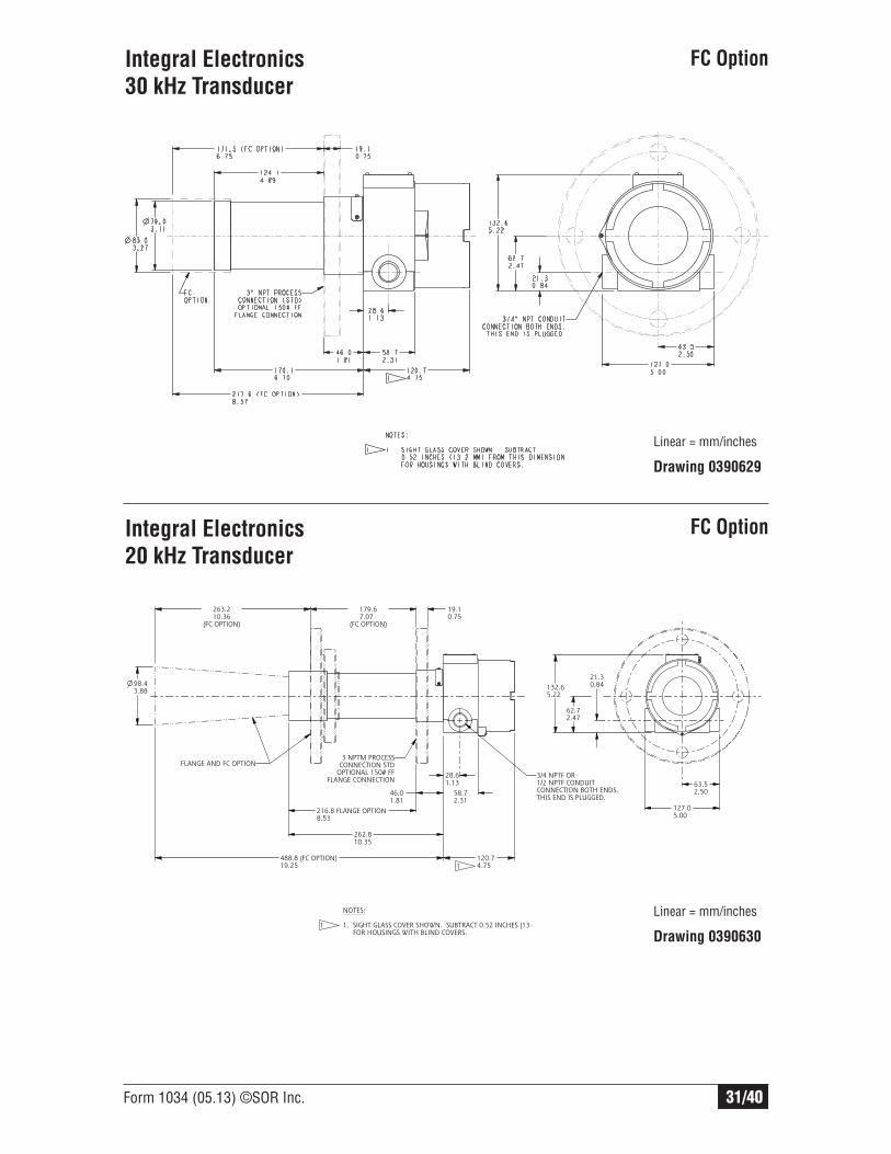
Integral Electronics
30 kHz Transducer
Linear = mm/inches
Drawing 0390629
Integral Electronics
20 kHz Transducer
Linear = mm/inches
Drawing 0390630
ISO-9001
14685 W 105TH ST LENEXA, KS 66215 USA913-888-2630SORINC.COM
21.30.84
62.72.47
132.65.22
63.52.50
127.05.00
28.61.13
120.74.75
58.72.31
262.810.35
488.8 (FC OPTION)19.25
216.8 FLANGE OPTION8.53
263.210.36
(FC OPTION)
179.67.07
(FC OPTION)
46.01.81
19.10.75
98.43.88
PRODUCT CERTIFICATION DRAWINGALL DIMENSIONS ARE ±1/16 IN
DRAWN BY
K MITCHELLCHECKED BY
3/4 NPTF OR1/2 NPTF CONDUITCONNECTION BOTH ENDS.THIS END IS PLUGGED.
3 NPTM PROCESSCONNECTION STD
OPTIONAL 150# FFFLANGE CONNECTION
FLANGE AND FC OPTION
1
FC Option
FC Option
NOTES: 1. SIGHT GLASS COVER SHOWN. SUBTRACT 0.52 INCHES (13 FOR HOUSINGS WITH BLIND COVERS.
1

32/40 Form 1034 (05.13) ©SOR Inc.
Integral Electronics
15 kHz Transducer
Integral Electronics
10 kHz Transducer
Linear = mm/inches
Drawing 0390631
15 kHzA B C D
289.911.77
255.310.05
252.79.95
534.721.05
Linear = mm/inches
Drawing 0390646
Integral Electronics
5 kHz Transducer
Linear = mm/inches
Drawing 0390632
FC Option

Form 1034 (05.13) ©SOR Inc. 33/40
Electronics
Operating voltage 110 VAC version ......................... 22 – 27 VDC and/or 100 – 126 VAC 220 VAC version ........................ 22 – 27 VDC and/or 200 – 230 VACPower consumption 24 VDC power supply................. <10 W 110/220 VAC power supply ........ <10 VARelay output Integral version .......................... 2 Form ‘C’ (SPDT) Contacts Rated 10A @ 240 VAC Remote version .......................... 4 Form ‘C’ (SPDT) Contacts Rated 10A @ 240 VAC All relays have independently adjustable deadbands.
Analog output ............................................................... 4 – 20 mA or 20 – 4 mA (700 ohm Loop resistance)Digital output ................................................................ ModbusElectronic accuracy ....................................................... ±0.25% of Maximum RangeRemote cable length ..................................................... <100m (334 ft.)Remote cable type ........................................................ TYCAB DMC 71402 or Carol Cable CO764 7 conductor, 22 Ga. shielded cableDisplay .......................................................................... 2 Line 8 Character LCD DisplayMemory ........................................................................ Non-Volatile with >10 Years RetentionElectrical connections ................................................... 2 x ¾” NPT(F) on Integral UnitsHazardous area classification ........................................ EEx md IIB + H2 (Integral only)
* These values are based on dB (Lin) Peak, unweighted. Consult local sound protection standards for conversions and limits.
Design and specifications are subject to change without notice. For latest revision, see sorinc.com
Transducers
Transducer
Model/FrequencyBlanking Distance
Maximum Liquid/
Slurry Range
Maximum Solid/
Power Range
A - 5kHz 60 in. (1.52m) 260 ft. (80m) 260 ft. (80m)
B - 10kHz 48 in. (1.22m) 260 ft. (80m) 100 ft. (30m)
K - 15kHz 24 in. (0.61m) 65 ft. (20m) 33 ft. (10m)
C - 20kHz 24 in. (0.61m) 65 ft. (20m) 33 ft. (10m)
D - 30kHz 18 in. (0.46m) 33 ft. (10m) 10 ft. (3m)
Transducer
Model/Frequency
SPL* at 3 ft. (1 m)
in front of transducer
SPL* at 3 ft. (1 m)
to side of unit
SPL* at 3 ft. (1 m)
behind unit
A - 5kHz 137 dB 113 dB 100
B - 10kHz 138 dB 105 dB
K - 15kHz 135 dB 107 dB
C - 20kHz 132 dB 108 dB
D - 30kHz 129 dB 102 dB
Product Specifi cations

34/40 Form 1034 (05.13) ©SOR Inc.
Maximum operating pressure ...........................................................15 psig (1.0 BAR)
Operating temperatureIntegral Unit Display ................................................-40°F (-20°C) to 140°F (60°C)Integral Unit Electronics ...........................................-40°F (-40°C) to 140°F (60°C)Remote Display .......................................................+14°F (-10°C) to 140°F (60°C) Remote Electronics ..................................................-40°F (-40°C) to 140°F (60°C)Remote Transducer ..................................................-40°F (-40°C) to 140°F (60°C)
When the unit is in normal operation, several diagnostic features can be accessed by pressing the button. The top line of the display will scroll through five items detailed here as the button is pushed. The bottom line of the display will continue to show the normal output. Accessing the diagnostic feature will not affect analog or relay outputs.
Datum Description
GN Gain being currently applied to the received echo. (Includes GR below.)
GR Amount of recover gain currently being added to the normal gain curve.
NL Background or electrical noise detected by the transducer. If the unit is behaving erratically, noise may be the problem.
TTemperature detected at the face of the transducer. This is displayed in Fahrenheit or Celsius depending on the units of measurement selected (feet or meters).
E The actual distance currently being detected, regardless of damping or window location.
Troubleshooting
echOsonix units use an increasing gain curve, or sensitivity curve, to detect echoes. As an echo comes from a target at a longer distance from the transducer, the gain applied to that echo increases. This allows the unit to compensate for sound strength losses from distance. Some of the values that define this gain curve are constant in all but the most challenging applications and should only be adjusted by factory-trained personnel. Other values can be adjusted as needed to solve minor problems. These values are found in the “Trim” menu under the “Gain Trim” section as seen on page 27.
Form 1034 (05.13) ©SOR Inc. 35/40
Consult Factory
Gain Applied to Echoes (%)
0% 100% GS GN
DS
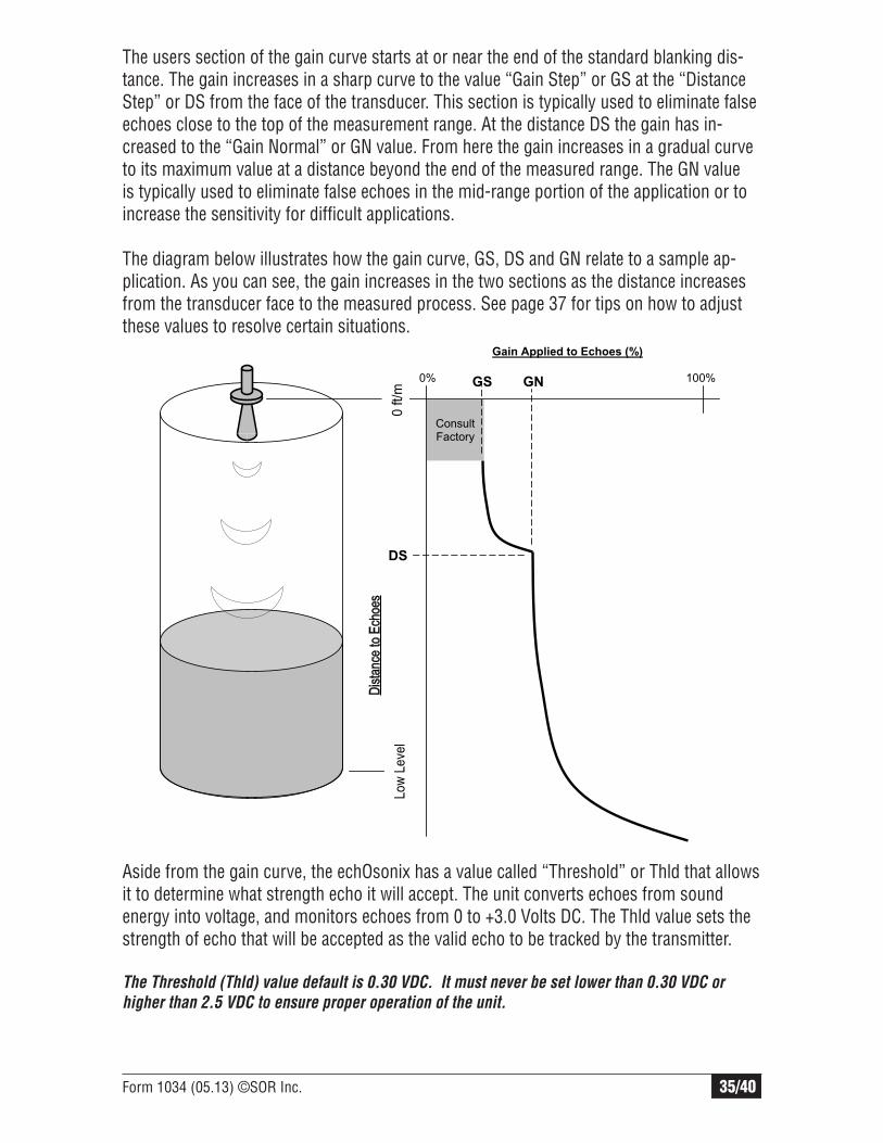
The users section of the gain curve starts at or near the end of the standard blanking dis-tance. The gain increases in a sharp curve to the value “Gain Step” or GS at the “Distance Step” or DS from the face of the transducer. This section is typically used to eliminate false echoes close to the top of the measurement range. At the distance DS the gain has in-creased to the “Gain Normal” or GN value. From here the gain increases in a gradual curve to its maximum value at a distance beyond the end of the measured range. The GN value is typically used to eliminate false echoes in the mid-range portion of the application or to increase the sensitivity for difficult applications.
The diagram below illustrates how the gain curve, GS, DS and GN relate to a sample ap-plication. As you can see, the gain increases in the two sections as the distance increases from the transducer face to the measured process. See page 37 for tips on how to adjust these values to resolve certain situations.
Aside from the gain curve, the echOsonix has a value called “Threshold” or Thld that allows it to determine what strength echo it will accept. The unit converts echoes from sound energy into voltage, and monitors echoes from 0 to +3.0 Volts DC. The Thld value sets the strength of echo that will be accepted as the valid echo to be tracked by the transmitter.
The Threshold (Thld) value default is 0.30 VDC. It must never be set lower than 0.30 VDC or
higher than 2.5 VDC to ensure proper operation of the unit.

36/40 Form 1034 (05.13) ©SOR Inc.
0.50 VDC 2.30 VDC
Echo Signal Strength (VDC)
0.00 VDC +3.00 VDC
Inlet Pipe
Thld = 1.00 VDC
Transmitter monitors this echo only
The gain curve and threshold settings previously discussed can be used to modify the echOsonix for difficult installations, to eliminate false echoes and to increase sensitivity in tough applications. There are many other potential situations that can be corrected by other means. Pages 37 and 38 cover some ideas on how to troubleshoot problems and some suggested ways to correct them.
The flowcharts below give suggested ways to correct specific problems using the values found in the “Trim” menu under the “Gain Trim” section as seen on page 27. In many instances the values in that menu must be changed in combinations of two or more to get the desired effect. The charts below are intended to be guidelines for doing this, not hard and fast rules. Each installation and application is unique and may require a unique combination of parameter settings to solve a problem.
If your application is working properly and track the process correctly, do not modify these settings.
When making changes to these parameters, the top line of the display shows the actual value, and the bottom line show the distance from the sensor face to the echo the unit is currently reading. It is important to know the correct distance you are trying to obtain while troubleshooting so that you know when the changes you are making have the desired effect.
If the suggestions here do not solve the problem, contact a factory technician for assistance.
The diagram below is an example of echoes received in the tank shown as seen on an oscilloscope. In this case, a threshold value of 1.00 VDC will ignore the inlet pipe but will read the process echo. Consult the Troubleshooting guidelines on page 34 before making adjustments to this value.

Form 1034 (05.13) ©SOR Inc. 37/40
Problem: When the process level is high, the unit seems to keep jumping down to a lower level reading.
Problem: The unit loses track of the process during filling/emptying only.
Problem: The unit keeps reading the end of my flange standpipe, not the process.
Decrease GS by 2 – 3%
Increase DS to false echo distance
Increase THLD until correct echo is read
Working? Press RUN
Yes
No Yes
No
Working?Press RUN
Increase GS by 3 – 5%
Decrease DS by 1 foot (0.3m)
Decrease THLD to 0.30 VDC
Working? Press RUN
Yes
No Yes
No
Working?Press RUN
Increase GN by 5 – 10%
Decrease DS by 1 foot (0.3m)
Decrease THLD to 0.30 VDC
Working? Press RUN
Yes
No Yes
No
Working?Press RUN
Decrease GS by 2 – 3%
Increase DS to 1 foot (0.3m) past end of standpipe
Increase THLD until correct echo is read
Working? Press RUN
Yes
No Yes
No
Working? Press RUN
Press RUN
Press RUN
Press RUN
Press RUN
Problem: The unit keeps reading the end of my flange standpipe, not the process.
Problem: The unit loses track of the process during filling/emptying only.
Problem: When the process level is high, the unit seems to keep jumping down to a lower level reading.
Problem: When the process level is low, the unit seems to keep jumping up to a higher level reading.
The following is a collection of tips gathered from experience to help ensure optimal performance in a variety of situations. Consider them all and use them as necessary since some may not apply to every circumstance.
General Installation
Installation is the key to performance in all cases. Improper installation or failure to follow the installation instructions accounts for the vast majority of performance problems. The echOsonix is designed to adapt to various situations and proper installation will significantly improve the performance.
When mounting the unit to the mating nozzle flange, it is recommended that a plastic flange with plastic bolts be used and, if possible, a rubber gasket. The bolts should only be tightened enough to keep the unit in place.
The echOsonix will not read through solid surfaces such as a window. Neither can it read a solids level through a liquid level (e.g. a sludge settling basin).
If there is no display upon wiring, check the following: - Is there power to the unit? - Is the unit properly wired? Are the wires secure (check by gently tugging on them with pliers)? - If using a DC power supply, is at least 24VDC supplied at the terminal block? - Are the fuses both good (AC and DC fuses)? They can be checked with an ohmmeter.

38/40 Form 1034 (05.13) ©SOR Inc.
Special Installations
The echOsonix can be mounted above a grating or decking. There are certain mounting requirements and parameter changes to make:
- The unit should not physically touch the grating. Mount the unit above the deck at least 6” (300mm). This will prevent excessive noise caused by interference with the grating.
- The “Blanking” distance should be extended past the lower surface of the grating. - Make sure the decking is not a solid surface – it must have at least 50% of its surface
area as open holes.
When the echOsonix is mounted inside a stilling well or bridle, there are some parameter changes that must be made to allow proper performance. These devices
provide intense focusing of echoes and it is very easy to overwhelm the transmitter if these changes are not made:
- Decrease GS to approximately 3 – 5%. - Increase DS to approximately 1 foot (300mm) longer than the stilling well or bridle. - If having difficulty with erratic readings after making the two changes above, increase
the THLD to 1.0 VDC.
Note: Stilling wells and bridles should be minimum 4” (100mm) inside diameter and
maximum 20 feet (6m) long.
If the output is erratic due to turbulence, intermittent obstructions, etc., decrease the “Speed” setting to the maximum possible rate of level increase, then increase the “Damping” parameter until acceptable stability is achieved.
Programming
Remember that all distance values are measured downward from the sensor face in all menus. This means that even if you are displaying Level or Level %, the Hi Level,
Lo Level and relay settings are still input and displayed as distance from the sensor face down.
In most cases the “Blanking” distance should be increased to a value slightly less then “Hi Level”. This will eliminate the possibility of false echoes above the measured range. Do not use a blanking value less than the stated minimum.

Form 1034 (05.13) ©SOR Inc. 39/40

40/40 Form 1034 (05.13) ©SOR Inc.
14685 West 105th Street, Lenexa, KS 66215 913-888-2630 800-676-6794 USA Fax 913-888-0767
Registered Quality System to ISO 9001
Printed in USA sorinc.com