efficiency enhancement of wireless power transfer system using...
TRANSCRIPT

Progress In Electromagnetics Research C, Vol. 68, 11–19, 2016
Efficiency Enhancement of Wireless Power Transfer SystemUsing MNZ Metamaterials
Tarakeswar Shaw*, Aritra Roy, and Debasis Mitra
Abstract—In this paper, a simple approach for efficiency enhancement of a wireless power transfersystem by using mu near zero (MNZ) type of metamaterial is proposed. A single slab containing one-sided periodic structures of 3×3 array of meander-line unit cell has been placed between transmittingand receiving coils in the wireless power transfer system. The presented metamaterial structure is lesscomplex than other reported metamaterial structures in the area of wireless power transfer system.The simulation and measurement have been performed with and without the metamaterial slab. Usingthe metamaterial slab, the maximum efficiency has been obtained about 55.3%, i.e., an improvementof efficiency around 15.7% is obtained compared to a wireless power transfer system without themetamaterials. Interestingly, the proposed wireless power transfer system shows a steady improvementof efficiency even if the distance between the transmitting and receiving coil is increased.
1. INTRODUCTION
Wireless Power Transfer (WPT) is an efficient approach for the transmission of electric power from oneplace to another through atmosphere without any physical link or contact. The concept of WPT wasfirst proposed and demonstrated by Nikola Tesla in his pioneer work [1]. There has been increasinginterest in the research and development of WPT, due to its wide applications in portable devices suchas mobile phone charging [2], laptop charging [3], automatic guided vehicles and robots [4], etc. Also,in the sector of biomedical applications, WPT is in very high demand such as data telemetry for retinalprosthesis [5], micro-robot endoscopy [6], magnetic resonance imaging (MRI) [7], etc. Therefore, WPThas a promising future in several fronts having different power level operations varying from milliwattin the case of biomedical applications to kilowatt units in the case of automobiles. WPT has also beenapplied over different distances ranging from millimetre to as large as metres.
Depending upon the application requirement, a WPT system can be divided into three possiblecategories: inductive coupling, resonant coupling and microwave power transmission. Inductive couplingand resonant coupling are used in short-range applications, and microwave power transmission systemfor long-range applications. In inductive coupling [2, 4–6], good mutual inductances among the coilsare required, which depend upon quality factor (Q) and coupling coefficient (k) among the coils. Ahigh value of coupling coefficient (k > 0.9) and precise orientation of the coils are necessary for efficientpower transfer [8]. In this system, the efficiency is limited by the quality factor of the coils and themutual coupling between the coils. The mutual coupling decreases rapidly due to increasing distancebetween the coils. In [9], it was first reported that magnetic resonant coupling using a non-radiativemid-range field was used for wireless power transfer, and the authors of [9] were able to transfer highefficiency power over the distance of two meters. After that, power transfer using magnetic resonancehas drawn great attention by several authors [3, 7], mainly due to its ability of transmitting power with
Received 11 August 2016, Accepted 19 September 2016, Scheduled 3 October 2016* Corresponding author: Tarakeswar Shaw ([email protected]).The authors are with the Department of Electronics & Telecommunication Engineering, Indian Institute of Engineering Science andTechnology, Shibpur, Howrah-711103, West Bengal, India.

12 Shaw, Roy, and Mitra
significant misalignment between coils, i.e., with low coupling coefficient (k < 0.2) [8]. For maximumpower transmission, high Q-factors and essentially same resonant frequencies are required for both thetransmitting (Tx) and receiving (Rx) coils. However, the main problems of this system are short rangepower transmission and low efficiency. In [10], a technique was reported to achieve higher efficiency andbetter range for WPT by connecting a parallel capacitor in both Tx and Rx ends of the coils.
In recent times, due to the unusual properties such as negative permittivity and/or negativepermeability, metamaterial (MTM) has been widely used for performance enhancement of the WPTsystem. There are various literatures by several authors in the context of the WPT using metamaterialto increase the efficiency and range [11–18]. In [11], for the first time, the use of MTM in the field of theWPT was introduced by using negative index MTM for the enhancement of the coupling coefficient andthe transfer efficiency. In [12], a rigorous theoretical analysis was presented for enhancement of WPT byusing metamaterial slab. In [13], Wang et al. proposed the use of magnetic metamaterials to enhance theevanescent wave coupling and improve the transfer efficiency of the wireless power transfer system basedon coupled resonators. Also, an efficient wireless power transfer system by using highly sub-wavelengthnegative refractive index (NRI) and negative permeability (MNG) metamaterial has been designed in[14]. Another technique for improving power transfer efficiency of a short-range telemetry system usingcompact magnetic metamaterial has been reported in [15]. In [16], an efficient wireless power transferhas been achieved by using modified mu-zero resonator (MZR), which provides stronger coupling thanthe other modes. In [17], with the help of zero refractive index property of the MTM, a highly efficientWPT system has also been reported. Very recently in [18], a ferrite loaded solenoid three-dimensional(3-D) MTM unit cell at low-frequency was designed for efficiency enhancement of WPT system. In[13, 18], the efficiency enhancement of WPT system has been achieved, but the proposed MTM unitcell structures are 3-D, and as a result, the system becomes complex and bulky. In [14], two differentMTM unit cell structures were printed on the both sides of the dielectric to obtain negative refractiveindex property of MTM, which is a little bit complicated to design. In [15], multilayer metamaterialslabs have been placed between Tx and Rx coils, which increases the overall size of the WPT system.In [16, 17], both sides with printed MTM unit cell has been used for WPT system, which increases thedesign complexity.
In this paper, we propose a simple technique for efficiency enhancement of WPT system by usingMNZ type of metamaterial. Here the MTM slab is designed from electric (ELC) resonator. The MTMunit cell is composed of a meander-line structure designed on a single side of dielectric instead of adouble-sided structure. A single slab of an array of 3×3 one-sided periodic structures of a meander-line unit cell has been placed between the transmitting and receiving coils in the WPT set up forefficiency enhancement. The MNZ as well as low loss behaviour of the MTM structure results inthe enhancement of power transfer efficiency by providing strong coupling between the coils. Thesimulation and measurement have been done with and without the MTM structure. With the help ofthe metamaterial placed in between Tx and Rx coils, the maximum efficiency is obtained about 55.3%.An improvement of efficiency around 15.7% is achieved.
2. CONFIGURATION AND CHARACTERIZATION OF METAMATERIAL SLAB
In the proposed WPT system, we use the MNZ property of the metamaterial, which is obtained froma MTM resonator having ELC behaviour. The MTM unit cell consists with the help of meander-linestructure designed on the single side of dielectric which eliminates the fabrication difficulties as requiredin the case of double-sided structures. The schematic configuration of the MTM unit cell is shown inFigure 1. The MTM unit cell consists of a meander-line structure on single side of an FR4 dielectricwhich has a dielectric constant of 4.4, dielectric thickness of 1.6 mm, and loss tangent of 0.02. Thepresented MTM structure is mainly inspired from [19]. The dimension of the MTM unit cell (Ls×Ws)is 60 × 60 mm2.
A normal incident plane wave having a polarized electric field in the x direction is considered for thecalculation of the scattering parameters of the MTM unit cell structure. The reflection and transmissioncoefficients are obtained from a single unit cell with the use of periodic boundary conditions. Thesimulated S-parameter (S11 & S21) plots of the unit cell are shown in Figure 2. It can be observedfrom Figure 2 that over the range of 20 MHz to 30 MHz, the MTM unit cell structure provides better

Progress In Electromagnetics Research C, Vol. 68, 2016 13
Figure 1. Schematic configuration of metamaterial unit cell. The meander line dimensions shown ininset are Lm = 58.8 mm, Tm = 0.4 mm, Gm = 0.6 mm.
Figure 2. The simulated S11 and S21 plots of the MTM unit cell.
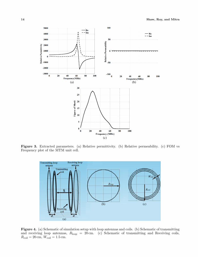
transmission of electromagnetic power and significantly low reflection coefficient. The extracted relativepermittivity and permeability plots of the unit cell structure are shown in Figures 3(a) and 3(b),respectively. The MNZ behaviour of the MTM structure is observed over the range of frequency fromFigure 3(b).
Generally, the loss in the metamaterial is represented by figure of merit (FOM). The FOM is definedas the ratio of the real and imaginary parts of refractive index (n), |Re(n)/Im(n)|, of a metamaterialunit cell. The FOM plot of the unit cell structure is shown in Figure 3(c). It is observed from thefigure that in frequency range of 20 MHz to 30 MHz the value of FOM is quite high, which means thata low loss behavior exist in this range. The retrieval method based on Kramers-Kronig relationship[20] has been used for parameter extraction. The simulation of MTM unit cell has been done using thehigh-frequency structure simulator (HFSS). The MTM slab has been designed by an array of 3× 3 unitcells with the dimension of 180×180 mm2, which is used for improving efficiency of the WPT system inthe next section.
3. SIMULATION AND EXPERIMENTAL SETUP OF PROPOSED WIRELESSPOWER TRANSFER SYSTEM
The simulation of the WPT system with and without metamaterial is performed by COMSOLMultiphysics. In this paper, a four-coil based structure is proposed to design the WPT system, becausemulti-coil system provides high Q-factor and strong coupling for maximum power transmission [21].This system consists of a transmitting loop antenna, a receiving loop antenna, a transmitting coil anda receiving coil. Power is directly fed to the transmitting loop antenna that has a radius (Rloop) of
14 Shaw, Roy, and Mitra
(a) (b)
(c)
Figure 3. Extracted parameters. (a) Relative permittivity. (b) Relative permeability. (c) FOM vsFrequency plot of the MTM unit cell.
(a)
(b) (c)
Figure 4. (a) Schematic of simulation setup with loop antennas and coils. (b) Schematic of transmittingand receiving loop antennas, Rloop = 20 cm. (c) Schematic of transmitting and Receiving coils,Rcoil = 20 cm, Wcoil = 1.5 cm.
Progress In Electromagnetics Research C, Vol. 68, 2016 15
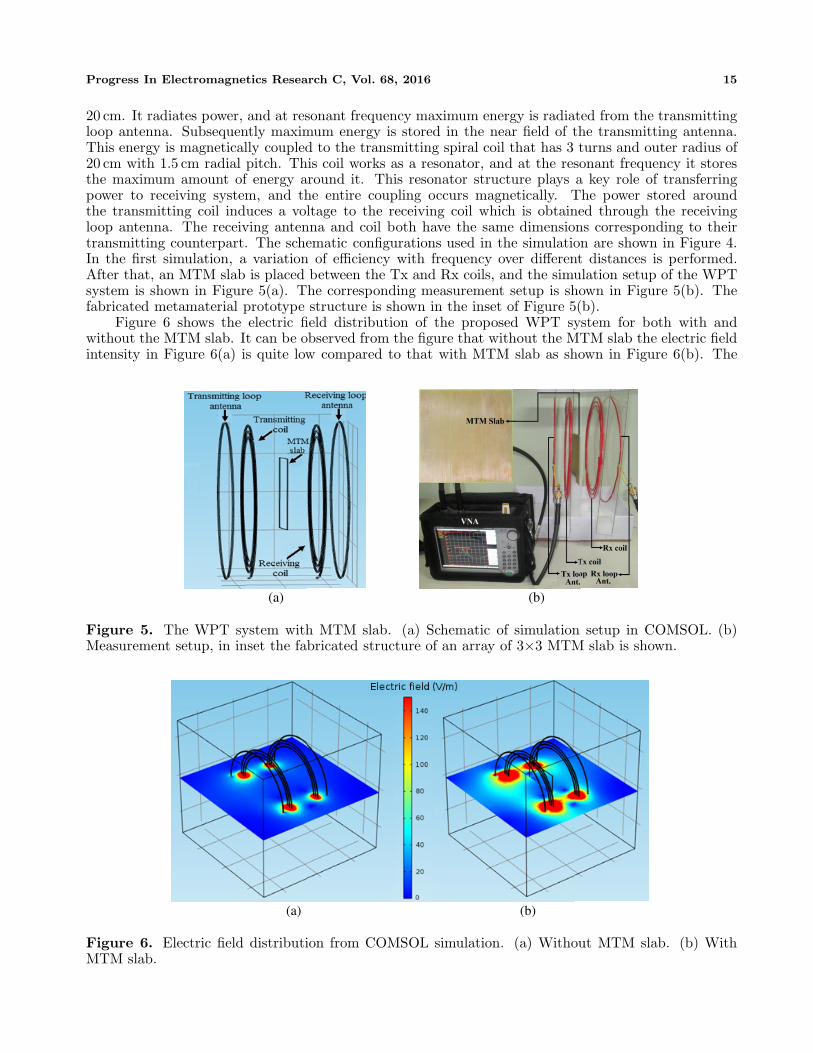
20 cm. It radiates power, and at resonant frequency maximum energy is radiated from the transmittingloop antenna. Subsequently maximum energy is stored in the near field of the transmitting antenna.This energy is magnetically coupled to the transmitting spiral coil that has 3 turns and outer radius of20 cm with 1.5 cm radial pitch. This coil works as a resonator, and at the resonant frequency it storesthe maximum amount of energy around it. This resonator structure plays a key role of transferringpower to receiving system, and the entire coupling occurs magnetically. The power stored aroundthe transmitting coil induces a voltage to the receiving coil which is obtained through the receivingloop antenna. The receiving antenna and coil both have the same dimensions corresponding to theirtransmitting counterpart. The schematic configurations used in the simulation are shown in Figure 4.In the first simulation, a variation of efficiency with frequency over different distances is performed.After that, an MTM slab is placed between the Tx and Rx coils, and the simulation setup of the WPTsystem is shown in Figure 5(a). The corresponding measurement setup is shown in Figure 5(b). Thefabricated metamaterial prototype structure is shown in the inset of Figure 5(b).
Figure 6 shows the electric field distribution of the proposed WPT system for both with andwithout the MTM slab. It can be observed from the figure that without the MTM slab the electric fieldintensity in Figure 6(a) is quite low compared to that with MTM slab as shown in Figure 6(b). The
(a) (b)
Figure 5. The WPT system with MTM slab. (a) Schematic of simulation setup in COMSOL. (b)Measurement setup, in inset the fabricated structure of an array of 3×3 MTM slab is shown.
(a) (b)
Figure 6. Electric field distribution from COMSOL simulation. (a) Without MTM slab. (b) WithMTM slab.

16 Shaw, Roy, and Mitra
field simulation shows that the coupling can be enhanced between Tx and Rx coils with the MNZ aswell as low loss MTM, and as a result of this the power transfer efficiency is improved.
The value of the transmission coefficient (S21) is measured as the efficiency of the WPT is expressedas |S21|2 in [10, 13]. The coils are made according to the specification mentioned earlier used insimulation. The distance (d) between the loop antenna and coil is optimized at 5 cm to obtain themaximum power transfer efficiency. The distance (S) between the Tx and Rx coils is varied at 5 cm,10 cm, 15 cm and 20 cm. For each measurement setup, the value of S21 is measured using AnritsuMS2025B vector network analyser (VNA) to obtain the efficiency of the system.
4. RESULTS AND DISCUSSIONS
Here, the simulated and measured efficiencies are observed over different frequencies and distances.Obviously, the efficiency will decrease with an increase in distance between the coils. However, theamount of improvement in efficiency with metamaterial slab for different distances is the major pointof our observation. So, the frequency is varied over a range of 20 MHz to 30 MHz, setting the distancesbetween the transmitting and receiving coils at 5 cm, 10 cm, 15 cm and 20 cm, respectively. Boththe transmitter and receiver sides, the distance between the loop antenna and coil are kept at 5 cm.The maximum efficiency is observed when both coils are at minimum distance, i.e., 5 cm apart inthis proposed design. Here without metamaterial, the maximum efficiencies of 42.3% and 39.6 % areobtained from simulation and measurement, respectively. After that, the metamaterial slab is placedbetween the coils and maximum efficiencies of 57.4% in the simulation and 55.3% in measurement areobtained. So, an improvement of efficiency around 15.7% is obtained using metamaterial in this case.Figures 7(a) and 7(b) show the simulated and measured efficiencies versus frequency plots for with andwithout MTM at 5 cm and 10 cm, respectively.
(b)(a)
Figure 7. Plot of efficiency vs frequency at different distances between Tx and Rx coils. (a) 5 cm. (b)10 cm.
Efficiency enhancement for different distances is obtained and summarised in Table 1. The graphicalplot of efficiency against distance between Tx and Rx coils of the WPT system is shown in Figure 8. Itcan be observed from Figure 8 that by using MTM slab, a significant amount of efficiency enhancementis achieved. It is also noticed that the efficiency improvement remains steady even if the distancebetween the Tx and Rx coils is varied.
A comparison between the present proposed work and other reported WPT systems using an MTMstructure is shown in Table 2. It can be pointed out from the table that the presented unit cell offerslow design complexity compared to all other MTM unit cell structures used to enhance the efficiency

Progress In Electromagnetics Research C, Vol. 68, 2016 17
Figure 8. Plot of efficiency vs distance between Tx and Rx coils of the WPT system.
Table 1. Comparison of the different results obtained from the measurement during distance variationbetween Tx and Rx coils.
Distance
between Tx
& Rx coils
(cm)
Operating
frequency
(MHz)
Efficiency
without
MTM (%)
Efficiency
with
MTM (%)
Efficiency
enhancement
(%)
5 24.3 39.6 55.3 15.7
10 25.0 36.4 51.6 15.2
15 26.2 32.8 45.7 12.9
20 27.4 30.5 41.2 10.7
Table 2. Comparison between the proposed work and other reported wireless power transfer systemusing metamaterial.
ReportedWPTsystem
MTM unitcell type
Designconfigurationof unit cell
Designcomplexityof unit cell
OperatingFrequency
(MHz)
DistanceBetweenTx & Rxcoils (cm)
MeasuredEfficiency
(%)
J. H. Park,et al.,
2014 [16]
Mu-zeroresonator
Both sidedstructure
Moderate 14.2510
69.319.7
H. Kim,et al.,
2014 [17]ZRI
Both sidedstructure
Moderate 6.781015
54.445.2
E. S. G.Rodriguez,
et al.,2016 [18]
Magneticresonator
Three-dimensional(3-D)
High 5.57 4.5 35
ProposedWork
MNZSingle sidedstructure
Low
24.325.026.227.4
5101520
55.351.645.741.2

18 Shaw, Roy, and Mitra
of a WPT system. It is also observed that the measured WPT efficiency is better than than in [18].Though in [16], the efficiency for shorter distance is better than the proposed work, but in the case oflonger distances the proposed work is much better.
5. CONCLUSION
A simple approach for efficiency enhancement of the WPT system by using MNZ as well as low lossmetamaterial is presented. The proposed setup has been built for WPT system using an MTM slab.In measurement, the efficiency is increased from 39.6% to 55.3% using an MTM slab, so around 15.7%improvement of efficiency is obtained compared to WPT without the MTM slab. It is noticed that theproposed WPT system shows a nearly steady improvement of efficiency even if the distance betweenthe Tx and Rx coil is increased. The discrepancies between measured and simulated results are due tothe conductive loss of wires and misalignment of coils in measurement setup.
ACKNOWLEDGMENT
For research support T. Shaw acknowledges the Visvesvaraya PhD scheme for Electronics & IT researchfellowship award and D. Mitra acknowledges the Visvesvaraya Young Faculty research fellowship award,under DeitY, Govt. of India.
REFERENCES
1. Tesla, N., “Apparatus for transmitting electrical energy,” US Patent, Serial No. 371817, 1–4, Dec.1914.
2. Olvitz, L., D. Vinko, and T. Svedek, “Wireless power transfer for mobile phone charging device,”MIPRO, Proc. of the 35th International Convention, 141–145, Opatija, Croatia, May 2012.
3. Nguyen, V. T., S. H. Kang, J. H. Choi, and C. W. Jung, “Magnetic resonance wireless powertransfer using three-coil system with single planar receiver for laptop applications,” IEEE Tran.Consum. Electron., Vol. 61, No. 2, 160–166, May 2015.
4. Elliott, G. A. J., R. Stefan, G. A. Covic, and J. T. Boys, “Multiphase pickups for large lateraltolerance contactless power-transfer system,” IEEE Tran. Ind. Electron., Vol. 57, No. 5, 1590–1598, May 2010.
5. Wang, G., W. Liu, M. Sivaprakasam, M. Zhou, J. D. Weiland, and M. S. Humayun, “A dual bandwireless power and data telemetry for retinal prosthesis,” Proc. IEEE EMBS Annual InternationalConference, 4392–4395, New York City, USA, Aug.–Sep. 2006.
6. Yan, G., D. Ye, P. Zan, K. Wang, and G. Ma, “Micro-robot for endoscope based on wireless powertransfer,” Proc. IEEE International Conference on Mechatron and Automat, 3577–3581, Harbin,China, Aug. 2007.
7. Freire, M. J., R. Marques, and L. Jelinek, “Experimental demonstration of a µ = −1 metamateriallens for magnetic resonance imaging,” Appl. Phys. Lett., Vol. 93, 231108, 1–3, Dec. 2008.
8. Wang, B., W. Yerazunis, and K. H. Teo, “Wireless power transfer: metamaterials and array ofcoupled resonators,” Proc. IEEE, Vol. 101, No. 6, 1359–1368, Jun. 2013.
9. Kurs, A., A. Karalis, R. Moffatt, J. D. Joannopoulos, P. Fisher, and M. Soljacic, “Wireless powertransfer via strongly coupled magnetic resonances,” Science, Vol. 317, 83–86, Jul. 2007.
10. Kim, Y. and S. Lim, “Compact magnetic coupled resonator with high efficiency during misalignedwireless power transmission,” Journal of Electromagnetic Waves and Applications, Vol. 27, No. 15,1942–1948, Aug. 2013.
11. Wang, B., T. Nishino, and K. H. Teo, “Wireless power transmission efficiency enhancement withmetamaterials,” Proc. IEEE International Conference on Wireless Information Technology andSystem (ICWITS), 1–4, Honululu, HI, USA, Sep. 2010.
12. Urzhumov, Y. and D. R. Smith, “Metamaterial-enhanced coupling between magnetic dipoles forefficient wireless power transfer,” Phys. Rev. B, Vol. 83, 205114, 1–10, May 2011.

Progress In Electromagnetics Research C, Vol. 68, 2016 19
13. Wang, B., K. H. Teo, T. Nishino, W. Yerazunis, J. Barnwell, and J. Zhang, “Experiments onwireless power transfer with metamaterials,” Appl. Phys. Lett., Vol. 98, 254101, 1–3, Jun. 2011.
14. Fan, Y., L. Li, S. Yu, C. Zhu, and C. Liang, “Experimental study of efficient wireless power transfersystem integrating with highly sub-wavelength metamaterials,” Progress In ElectromagneticsResearch, Vol. 141, 769–784, Aug. 2013.
15. Rajagopalan, A., A. K. RamRakhyani, D. Schurig, and G. Lazzi, “Improving power transferefficiency of a short-range telemetry system using compact metamaterials,” IEEE Tran. Microw.Theory Tech., Vol. 62, No. 4, 947–955, Apr. 2014.
16. Park, J. H., B. C. Park, Y. H. Ryu, E. S. Park, and J. H. Lee, “Modified mu-zero resonator forefficient wireless power transfer,” IET Microw. Ant. Propag., Vol. 8, No. 12, 912–920, Mar. 2014.
17. Kim, H. and C. Seo, “Highly efficient wireless power transfer using metamaterial slab with zerorefractive property,” Electronics Lett., Vol. 50, No. 16, 1158–1160, Jul. 2014.
18. Rodriguez, E. S. G., A. K. Ram Rakhyani, D. Schurig, and G. Lazzi, “Compact low frequencymetamaterial design for wireless power transfer efficiency enhancement,” IEEE Tran. Microw.Theory Techn., Vol. 64, No. 5, 1644–1654, May 2016.
19. Kolb, P. W., T. S. Salter, J. A. McGee, H. D. Drew, and W. J. Padilla, “Extreme subwave lengthelectric GHz metamaterials,” J. Appl. Phys., Vol. 110, 054906, 1–5, Sep. 2011.
20. Szabo, Z., G. H. Park, R. Hedge, and E. P. Li, “A unique extraction of metamaterial parametersbased on Kramers-Kronig relationship,” IEEE Trans. Microw. Theory Tech., Vol. 58, No. 10, 2646–2653, Oct. 2010.
21. RamRakhyani, A. K. and G. Lazzi, “On the design of efficient multi-coil telemetry system forbiomedical implant,” IEEE Tran. Biomedical Circuits Sys., Vol. 7, No. 1, 11–23, Feb. 2013.