eclipse sam iot 2020 security ai modelling
TRANSCRIPT

1st Eclipse Research International Conference on Security, Artificial Intelligence and Modelling
for the next generation Internet of Things
17-18 September, 2020
Eclipse SAM IoT 2020| |Security ModellingAI
Immagini @Shutterstock, Inc
PROCEEDINGS
Enrico Ferrera Philippe Krief
EDITORS
Eclipse Foundation, Germany LINKS Foundation, Italy
CO-ORGANIZED BY
BRAIN-IoT EU H2020 Project IoT European Security and Privacy Projects
SUPPORTED BY

SAM IoT 2020
Proceedings of the
1st Eclipse Research International Conference on Security, Artificial Intelligence
and Modelling for the next generation Internet of Things
Virtual Conference | September 17-18, 2020
CO-ORGANIZED BY
Eclipse Foundation, Germany
LINKS Foundation, Italy
SUPPORTED BY
BRAIN-IoT, EU H2020 Project, Grant agreement 780089

Copyright © 2020 for the individual papers by the papers' authors.
Copyright © 2020 for the volume as a collection by its editors.
This volume and its papers are published under the Creative Commons License Attribution 4.0 International
(CC BY 4.0).
Edited by Enrico Ferrera and Philippe Krief
Submitted by Enrico Ferrera
Published on ceur-ws.org
ISSN 1613-0073
https://events.eclipse.org/2020/sam-iot/

III
BRIEF CONTENTS
ORGANIZING COMMITTEES .................................................................................................................................IV
INVITED SPEAKERS .................................................................................................................................................IV
PROGRAM COMMITTEE .......................................................................................................................................... V
FOREWORD .............................................................................................................................................................. VII
CONTENTS ..................................................................................................................................................................IX

IV
ORGANIZING COMMITTEES
GENERAL CHAIRS
Enrico Ferrera, LINKS Foundation, Italy
Philippe Krief, Eclipse Foundation, Germany
PROGRAM COMMITTEE CHAIR
Rosaria Rossini, LINKS Foundation, Italy
LAYOUT DESIGNER
Ilaria Bosi, LINKS Foundation, Italy
PUBLICITY
Susan Iwai, Eclipse Foundation, Germany
INVITED SPEAKERS
Henrik Plate
SAP Security Research
Germany
Paul-Emmanuel Brun
Airbus Cybersecurity
France

V
PROGRAM COMMITTEE
Alessio Angius, ISI Foundation, Italy
Luca Anselma, University of Turin, Italy
Paolo Azzoni, Eurotech, Italy
Alessandra Bagnato, Softeam, France
Peter Bednár, Technical University of Kosice,
Slovakia
Ilaria Bosi, LINKS Foundation, Italy
Paolo Brizzi, Competence Center Industry
Manufacturing 4.0, Italy
Benoit Combemale, University of Toulouse INRIA,
France
Davide Conzon, LINKS Foundation, Italy
João Pedro Correia dos Reis, Faculty of
Engineering, University of Porto – FEUP, Portugal
Maria Teresa Delgado, Eclipse Foundation,
Germany
Frederic Desbiens, Eclipse Foundation, Germany
Charalampos Doukas, Amazon Web Services,
Germany
Juliver Gil, Universidad de Antioquia, Colombia
Laurent Gomez, SAP Security Research, Germany
Gil Gonçalves, Faculty of Engineering, University
of Porto – FEUP, Portugal
Marco Jahn, Eclipse Foundation, Germany
Prabhakaran Kasinathan, Siemens AG -
Cybersecurity Technologies, Germany
Thomas Krousarlis, INLECOM Innovation, Greece
Zakaria Laaroussi, Ericsson, Finland
Konstantinos Loupos, INLECOM Innovation,
Greece
Cesar Marin, Information Catalyst for Enterprise –
ICE, United Kingdom
Yod Samuel Martín, Universidad Politécnica de
Madrid, Spain
Claudio Pastrone, LINKS Foundation, Italy
Nikolaos Petroulakis, Foundation for Research and
Technology Institute of Computer Science, Greece
Virginia Pilloni, Università di Cagliari, Italy
Ivana Podnar Žarko, University of Zagreb, Faculty
of Electrical Engineering and Computing, Croatia
Mohammad Rifat Ahmmad Rashid, University of
Liberal Arts Bangladesh – ULAB, Bangladesh
Alejandra Ruiz Lopez, Tecnalia, Spain
Julian Schütte, Fraunhofer AISEC, Germany
Xu Tao, LINKS Foundation, Italy
Mark Vinkovits, Pasero, Hungary
Rui Zhao, LINKS Foundation, Italy

VI

VII
FOREWARD
The adoption of the Internet of Things (IoT) is drastically increasing in every application domain, contributing to the
rapid digitalization of contemporary society. Current IoT scenarios are characterized by constantly increasing demands
in terms of non-functional requirements, from low latency to high reliability, dependability, and dynamic resources
allocation. This paradigm shift, also considered as the next evolutionary phase of IoT, is expected to create numerous
opportunities for the technology market supporting applications in multiple areas, i.e. Smart Factories, Smart Cities,
Critical Infrastructures, Cooperative Service Robotics, etc. To cope with these demanding requirements, a multitude of
novel technologies - such as Edge Computing, Artificial Intelligence and Analytics, Digital Twin, as well as Security,
Privacy and Trust schemes – are being investigated in order to be adopted in current IoT architectures standards,
identifying efficient integration schemes with proper design patterns. Hence, designing and managing the next
generation of IoT-based systems is set to become even more complex.
This book contains the proceedings of the 1st Eclipse International Conference on Security, Artificial Intelligence and
Modeling for the next-generation Internet of Things (SAM IoT 2020).
SAM IoT 2020 is the first scientific conference organized by Eclipse Foundation with the aim of promoting the building
of a richer public domain culture within the research community, with special attention to applied research. SAM IoT
2020 has organized a call for papers to collect the latest research results in Europe and all around the world, with a
specific focus on the open issues related to Security, Artificial Intelligence and Modelling in the next-generation of
Internet of things applications. SAM IoT is also supported by the EU-funded H2020 BRAIN-IoT project. As a project
focused on the definition and implementation of novel architectures and methodologies for supporting the developers
and operators of modern IoT applications to deal with the increasing complexity and dynamicity of IoT systems in Smart
city, Industry and Robotics domains, BRAIN-IoT is among the pioneer projects on the Next-Generation IoT paradigm.
For this reason, LINKS Foundation, as coordinator of the BRAIN-IoT project, participates in the organization of SAM
IoT 2020 to promote the discussion around the Next-Generation IoT research topics, bringing together participants from
research and industry.
Submissions, with authors from 16 different countries spread across Europe, Asia and the United States have been
received. To evaluate each submission, a blind paper review was performed by the Technical Program Committee,
whose members are highly qualified researchers in SAM IoT topic areas. Each paper was reviewed by at least three
reviewers. Based on those reviews, papers that adequately balanced quality, originality and relevance to the conference
themes were selected. Based on the classifications provided, 11 papers have been selected.
The conference also featured 2 keynote lectures delivered by experts, namely Henrik Plate (SAP Security Research) and
Paul-Emmanuel Brun (AIRBUS CyberSecurity). These talks contributed to increasing the overall quality of the
conference and to provide a deeper understanding of the conference fields of interest.
The proceedings of SAM IoT 2020 will be submitted for publication to CEUR Workshop Proceedings (CEUR-WS.org),
which is a free open-access publication service at Sun SITE Central Europe operated under the umbrella of RWTH
Aachen University. CEUR-WS.org is a recognized ISSN publication series, ISSN 1613-0073.
We believe the proceedings published demonstrate new and innovative solutions, and highlight challenging technical
problems in each of the SAM IoT fields.
To recognize the best submission, an award based on the paper review scores, as assessed by the Technical Program
Committee was conferred at the closing session of the conference.
As a final point, we would like to express our thanks, first of all, to the authors of the technical papers, whose work and
dedication made it possible to put together a program that we believe is very exciting and of high technical quality.
Next, we would like to thank all the members of the program committee, who helped us with their expertise and time.

VIII
We would also like to thank the invited speakers for their invaluable contributions and for sharing their vision in their
talks. Finally, we acknowledge the professional support of the SAM IoT 2020 team for all organizational processes,
especially given the need to introduce online streaming, breakouts management, direct messaging facilitation and other
web-based activities in order to make it possible for SAM IoT 2020 authors to present their work and share ideas with
colleagues in spite of the logistic difficulties caused by the current pandemic situation.
Enrico Ferrera
LINKS Foundation, Italy
Philippe Krief
Eclipse Foundation, Germany
IX
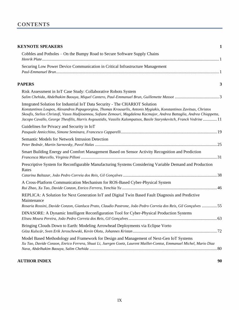
CONTENTS
KEYNOTE SPEAKERS 1
Cobbles and Potholes – On the Bumpy Road to Secure Software Supply Chains
Henrik Plate .................................................................................................................................................................... 1
Securing Low Power Device Communication in Critical Infrastructure Management
Paul-Emmanuel Brun ....................................................................................................................................................... 1
PAPERS 3
Risk Assessment in IoT Case Study: Collaborative Robots System
Salim Chehida, Abdelhakim Baouya, Miquel Cantero, Paul-Emmanuel Brun, Guillemette Massot ......................................... 3
Integrated Solution for Industrial IoT Data Security - The CHARIOT Solution
Konstantinos Loupos, Alexandros Papageorgiou, Thomas Krousarlis, Antonis Mygiakis, Konstantinos Zavitsas, Christos
Skoufis, Stelios Christofi, Vasos Hadjioannou, Sofiane Zemouri, Magdalena Kacmajor, Andrea Battaglia, Andrea Chiappetta,
Jacopo Cavallo, George Theofilis, Harris Avgoustidis, Vassilis Kalompatsos, Basile Starynkevitch, Franck Vedrine ............. 11
Guidelines for Privacy and Security in IoT
Pasquale Annicchino, Simone Seminara, Francesco Capparelli ......................................................................................... 19
Semantic Models for Network Intrusion Detection
Peter Bednár, Martin Sarnovsky, Pavol Halas ................................................................................................................. 25
Smart Building Energy and Comfort Management Based on Sensor Activity Recognition and Prediction
Francesca Marcello, Virginia Pilloni .............................................................................................................................. 31
Prescriptive System for Reconfigurable Manufacturing Systems Considering Variable Demand and Production
Rates
Catarina Baltazar, João Pedro Correia dos Reis, Gil Gonçalves ....................................................................................... 38
A Cross-Platform Communication Mechanism for ROS-Based Cyber-Physical System
Rui Zhao, Xu Tao, Davide Conzon, Enrico Ferrera, Yenchia Yu ........................................................................................ 46
REPLICA: A Solution for Next Generation IoT and Digital Twin Based Fault Diagnosis and Predictive
Maintenance
Rosaria Rossini, Davide Conzon, Gianluca Prato, Claudio Pastrone, João Pedro Correia dos Reis, Gil Gonçalves .............. 55
DINASORE: A Dynamic Intelligent Reconfiguration Tool for Cyber-Physical Production Systems
Eliseu Moura Pereira, João Pedro Correia dos Reis, Gil Gonçalves .................................................................................. 63
Bringing Clouds Down to Earth: Modeling Arrowhead Deployments via Eclipse Vorto
Géza Kulscár, Sven Erik Jeroschewski, Kevin Olotu, Johannes Kristan .............................................................................. 72
Model Based Methodology and Framework for Design and Management of Next-Gen IoT Systems
Xu Tao, Davide Conzon, Enrico Ferrera, Shuai Li, Juergen Goetz, Laurent Maillet-Contoz, Emmanuel Michel, Mario Diaz
Nava, Abdelhakim Baouya, Salim Chehida ...................................................................................................................... 80
AUTHOR INDEX 90

X

Copyright © 2020 for this paper by its authors. Use permitted under Creative Commons License Attribution 4.0 International (CC BY 4.0).
Cobbles and Potholes – On the Bumpy Road to
Secure Software Supply Chains
Henrik Plate
SAP Security Research, Germany
Abstract — Open source software is ubiquitous – all across the stack, in the cloud and on-premise, on all devices, in commercial
and non-commercial offerings. This success, the dependency of the software industry on open source, combined with recent data
breaches and attacks, puts security into the spotlight. This talk will provide an overview - for sure opinionated, hopefully
controversial – about the state of affairs and current trends regarding the security of software supply chains, both from consumer
and producer perspective.
Brief Biography — Henrik Plate is a senior researcher at SAP Security Research. He received his MSc in Computer Science and
Business Administration in 1999 from the University of Mannheim. His current research focusses on the security of software supply
chains, esp. the use of open source components with known vulnerabilities and supply chain attacks. He is a co-author of Eclipse
Steady [5], which supports the detection, assessment, and mitigation of vulnerable open source dependencies in Java and Python
applications.
Securing Low Power Device Communication in
Critical Infrastructure Management
Paul-Emmanuel Brun
Airbus Cybersecurity,France
Abstract — An overview of a secure IoT data transmission ecosystem will be completed with a concrete example of a water
management use case from the Brain-IoT project. In this use case, to ensure high trust in the device’s data, we integrated an end-to-
end security layer that is compatible with battery-less devices with high constraints in terms of energy, power computation and
bandwidth.
Brief Biography — Passionate about cybersecurity, IoT and identity management, Paul-Emmanuel Brun, is expert in IoT system
security, and leading the innovation activities within AIRBUS CyberSecurity France. As a former security and identity management
engineer, he was involved in several European initiatives and contributes to several projects for the French MoD, from secure
architecture definition to integration of cybersecurity solution. After applying several patents linked to the cybersecurity of IT and
IoT systems, he is now focus on innovation and IoT system security.
1

2

Risk Assessment in IoTCase Study: Collaborative Robots System
Salim Chehida, Abdelhakim BaouyaUniversity of Grenoble Alpes, CNRS, VERIMAG F-38000
Grenoble, France{name.surname}@univ-grenoble-alpes.fr
Miquel CanteroRobotnik Automation S.L.L
Valencia, [email protected]
Paul-Emmanuel Brun, Guillemette MassotAirbus CyberSecurity SAS
Elancourt, France{name.surname}@airbus.com
Abstract—Security is one of the crucial challenges in the designand development of IoT applications. This paper presents anapproach that focuses on existing security standards to evaluateand analyse the potential risks faced by IoT systems. It begins byidentifying system assets and their associated vulnerabilities andthreats. A list of security objectives and technical requirementsare then defined to mitigate the risks and build a secure andsafe system. We use our approach to assess risks in the roboticsystem for supporting the movement of loads in a warehouse.
Index Terms—Security Risk Assessment, IoT, Threats, SecurityRequirements.
I. INTRODUCTION
Internet of Things (IoT) is a promising technology thatoffers significant improvements to various domains such ashealth, commerce, construction, buildings management, en-ergy, and transport. It reduces management costs, automatesthe monitoring of infrastructures and equipment, saves energy,and more. An IoT system consists of a network of smartdevices that collaborate with users to accomplish intelligentservices. It generally groups a large number of devices thatinteract using multiple communication technologies and pro-tocols.
In the last decade, IoT systems are increasingly susceptibleto various security issues, such as malicious access to servicesand network attacks. These problems have caused considerabledamage and affected the secrecy, integrity, and availabilityof information. There are several surveys, such as [1]–[4],that discuss vulnerabilities that can be exploited by attackersto damage IoT systems. Taking into account these risks andtheir possible consequences constitute one of the principalchallenges for the designer and developer of these systems.
Security Risk Assessment (SRA) is the process that aimsto identify the most critical threats and provide the requiredmeasures to avoid these threats. It aims to mitigate the risksand build a secure system while covering its vulnerabilities.Several SRA methodologies [5]–[9] have been proposed toevaluate risks and enforce a common level of security. How-
ever, these methods are generic, and they do not consider thecomplexity and the dynamic of IoT systems.
In this work, we present a new approach that considersexisting methodologies and standards for risk assessment inIoT systems. It starts by identifying the assets that should beprotected and evaluating the threats they face. Then, a list ofsecurity objectives and requirements are defined to defend thesystem against potential threats. We apply our approach to thecollaborative robots system. Our approach is different fromall the generic approaches mentioned above and presented inSection II. It is dedicated to IoT systems and takes into accountthe relevant domain model and standards, as well as the needfor evolution of these systems.
This paper is organized as follows: Section II presents themain approaches and standards for security assessment. Wegive an overview of our risk assessment approach in sectionIII, then we describe its different stages and apply them toour case study in sections IV to VI. Finally, we give ourconclusions in Section VII.
II. STATE OF THE ART
We first present the main security standards, then theexisting methods for risk assessment.
A. Security Standards
Security standards guide an organization in best securitypractices in order to enforce a common level of security by en-suring availability, integrity, and confidentiality requirements.Many countries and organizations have established standardsfor risk assessment and analysis. In this section, we brieflypresent the relevant common and IoT security standards.(a) Common Standards
• ISO/IEC 27002 [10]: International standard that givesgeneral guidance on the commonly accepted goals ofinformation security management. It describes generalprinciples structured around 36 security objectives and133 controls.
Copyright © 2020 for this paper by its authors. Use permitted under Creative Commons License Attribution 4.0 International (CC BY 4.0).
3

• AS/NZS 4360 [11]: The joint Australian/New Zealandrisk management standard that provides a genericframework for identifying, analysing, evaluating, treat-ing, monitoring, and communicating risk.
• ISO/IEC 27005 [12]: International standard that pro-vides guidelines for managing information securityrisks in an organization. The standard describes the riskmanagement process, which includes context establish-ment, risk assessment, risk treatment, risk acceptance,risk communication, and risk monitoring and review.
• BS7799 (ISO17799) [13]: British Standard (Codeof Practice for Information Security Management),evolved into ISO17799 (The Information SecurityStandard). It gives a basis guide for risk assessmentand information security management.
• NIST SP 800-30 [14]: Special Publications Risk Man-agement Guide for Information Technology Systemsstandard that provides practitioners with practical guid-ance for carrying out each of the three steps in the riskassessment process (i.e., prepare for the assessment,conduct the assessment, and maintain the assessment).It also discusses how organizational risk managementprocesses complement and inform each other.
• NIST SP 800-82 [15]: This standard guides on im-proving security in Industrial Control Systems (ICS),including Supervisory Control and Data Acquisi-tion (SCADA) systems, Distributed Control Systems(DCS), and other control system configurations suchas Programmable Logic Controllers (PLC).
• IEEE 1686 [16]: Standard for Intelligent ElectronicDevices Cyber Security Capabilities’ that defines func-tions and features to be provided in Intelligent Elec-tronic Devices (IEDs). The document addresses access,operation, configuration, firmware revision, and dataretrieval of an IED.
(b) IoT Security StandardsThe authors in [17] analyse the existing regional andinternational standards for IoT security and indicate theirlimitations. Among international standards:• ITU-T standards1 :
– Y.2060 provides reference models of IoT and showsgeneric security capabilities on every layer.
– Y.2063 covers the authorization of heterogeneousdevices of WoT.
– Y.2066 defines common requirements of IoT andalso security and privacy protection requirementsrelated to all the IoT actors.
– Y.2067 covers gateway security mechanisms in-cluding authentication, data encryption, privacyprotection, etc.
– Y.2068 defines concepts of functional frameworkand capabilities of IoT, including service provisionsecurity, security integration, security audit, etc.
1https://www.itu.int/en/ITU-T/Pages/default.aspx
– Y.2075 specifies the security capabilities of EHM(e-health monitoring) with IoT.
– Y.4112/Y.2077 specifies the concept, purpose, andcomponents of plug and play (PnP) capability ofthe IoT, including security-related requirements.
– Y.4553 specifies the requirements of the smart-phone as a sink node for IoT applications, includingauthentication and data protection capabilities.
– Y.4702 provides common requirements and ca-pabilities of device management (DM) in IoT,including security management capabilities suchas security event detection and reporting, devicesecurity assurance, and device security control.
• ISO/IEC standards: ISO/IEC 30128 [18] covers IoTsecurity related to sensor network application interface.
Among regional standards, ETSI (standards organizationin the telecommunication industry in Europe) recentlyprovided “ETSI TS103645” [19] (Cyber Security forConsumer Internet of Thing) standard that gives securitypractices for consumer devices connected to the Internet.
According to [17], most of the IoT security standardspresented above are just specification-level standards anda few of them are involved in availability and non-repudiation.
B. Risk Assessment Methods
EBIOS [9] is used for the assessment and treatment ofrisks associated with an Information System (IS). Its steps are:definition of the context, identification and estimation of thesecurity needs and eventual sources of threats, identificationand analysis of threat scenarios, and finally specificationof security objectives and measures to be implemented forrisk treatment. The goal of the EBIOS method is to createa common ground for security discussion between variousstakeholders in order to support management-level decision-making. One of the main strengths of the EBIOS approach isits modularity; its knowledge bases can be tuned to complywith local standards and best practices, and to include externalrepositories of attack methods, entities or vulnerabilities [20].
CRAMM [7] (CCTA Risk Analysis and ManagementMethod) is a qualitative risk assessment methodology thatconsists of the following steps: collection of data and definitionof objectives, identification and evaluation of system assets,threat and vulnerability assessment, and finally determiningcountermeasures.
AURUM [5] (Automated Risk and Utility Management)supports the NIST SP 800-30 standard [14]. It consists ofthe following steps: identification of risks and their impacts,implementation of adequate countermeasures, and evaluationof the impact of countermeasures.
CORAS [6] allows risk assessment, documentation of in-termediate results, and presentation of conclusions. The mainsteps of the methodology are: definition of security goals,
4

description of threats, risk estimation by giving likelihoodvalues for identified unwanted incidents, and risk treatment.
MEHARI [8] (MEthod for Harmonized Analysis of RIsk)aims to provide a risk management model compliant to ISO-27005 [12]. The steps of MEHARI are: establishment of theorganization context, identification and classification of assets,identification and analysis of risks, and finally quantificationand management of risks. MEHARI allows the analysis of thesecurity stakes and the preliminary classification of the IS en-tities according to three basic security criteria (confidentiality,integrity, and availability).
OCTAVE [21] (Operationally Critical Threat, Asset, andVulnerability Evaluation) method allows to define a risk-based strategic assessment and planning technique for systemsecurity. It is based on process broken into three phases: development of initial security strategies, identification ofinfrastructure vulnerabilities, and development of final securitystrategy and plans.
IT-Grundschutz [22] provides methods, processes, proce-dures, and measures to establish a system for informationsecurity management. It describes a two-tier risk assessment:one is designed for reaching a standard level of security, whilea second supplementary risk analysis can be undertaken bycompanies that desire an approach customized to their specificneeds or sector or that have special security requirements.IT-Grundschutz also provides lists of relevant threats andrequired countermeasures that can be adapted to the needsof an organization.
III. AN OUTLINE OF OUR METHODOLOGY
Starting from standards and methods presented in the pre-vious section, we define the risk assessment methodologydepicted in Figure 1.
Our method consists of four steps:
1) The first step identifies the assets based on the IoT domainmodel.
2) The second step specifies threats on the assets based oncommon threats database proposed by the risk assess-ment methods presented in Section II. In this work, weconsider EBIOS database [9], which is compatible withall relevant ISO standards and provides a complete listof possible threats (42 threats) relative to informationsystems. EBIOS threats database is widely used in riskassessment. Some works like [23] have used it for riskanalysis of IoT systems.
3) In the third step, security objectives are derived from thethreats. In this step, we extract relevant objectives (13objectives) for IoT systems from ISO-27002 [10] thatprovides a set of generic security objectives supported bya set of controls that are an important part of informationsecurity management.
4) In the last step, security requirements are built in orderto implement the security objectives and provide coun-termeasures of the identified threats.
Fig. 1. IoT Risk Assessment Methodology.
Our approach is iterative, and security requirements can berevised after the system assets have been refined. The resultsof each step should be checked with the customer.
In this work, we apply our method to the service roboticssystem. As shown in Figure 2, our system consists of a fleetof robots installed in a warehouse to support the movement ofdifferent loads.
Fig. 2. Service Robotics System.
The flow of these loads does not require any operator tocommand the fleet. Robots are expected to empty continuouslyan “unload area” where different loads are put together. Atsome point, the system needs to identify the different itemsand then asks a specific robot to pick it and place it in aspecific storage area following some predefined rules. It is alsoforeseen that in order to perform such activity, the system willneed to actuate IoT devices, for example, an automated doorin the middle of the robot’s path to “storage areas”.
5

IV. IDENTIFICATION OF ASSETS
ISO-27001 [24] defines an asset as “any tangible or intangi-ble thing or characteristic that has value to an organization”.In our approach, we refer to IoT domain model proposed by[25] to facilitate the identification of the system assets. In thismodel, the main concepts are: thing, device, user and resource.
As shown in Figure 3, Thing is the combination of PE(Physical Entity) together with its digital representation VE(Virtual Entity).
Fig. 3. IoT Things.
VE can be of both types:• Passive Digital Artefact (PDA): a digital representation
of PE stored in a database or similar form.• Active Digital Artefact (ADA): any type of active code or
software program usually be some sort of software agentor embedded application.
Device is a hardware with computing and network capabil-ities that allows to monitor or interact with PE. As shown inFigure 4, device can be:
• Sensor : allows to monitor PE.• Actuator : allows to act on PE.• Tag : allows to identify PE and can be read by sensors.User represents who interacts with PE physically or through
software interfaces. Users can either be humans or ADA.Resource is software components that can provide infor-
mation about PE, allow the execution of actuation tasks, oranalyse data provided by multiple sensors. Resources may behosted on a Device, or they could be hosted anywhere in thenetwork.
Table I presents examples of 16 assets identified in our casestudy. The system includes different types of devices, such assensors (e.g., A3, A4, A5) and actuators (e.g., A13, A14, A15).
V. IDENTIFICATION OF THREATS AND VULNERABILITIES
ISO-27001 [24] defines a threat as “a potential cause of anunwanted incident, which may result in harm to a system ororganization” and considers vulnerability as “weakness thatis related to the organizations’ assets, which sometimes couldcause an unexpected incident”.
As mentioned in Section III, our method considers a list ofgeneric threats from EBIOS database. In Table II taken from
Fig. 4. IoT Devices.
Asset ID Asset Description
A1 Mobile Robot: Embedded Computer
A2 Mobile Robot: Motion Control (motor driver)
A3 Mobile Robot: Sensor 1, RGBD Camera
A4 Mobile Robot: Sensor 2, Lidar
A5 Mobile Robot: Sensor 3, Odometry
A6 Mobile Robot: Lift Mechanism
A7 Mobile Robot: Battery (LiFePo)
A8 Mobile Robot: Network (Card)
A9 System: User Computer
A10 System: Network (Router and infrastructure)
A11 System: Mission Command (Outwards)
A12 System: Robot State (Inwards)
A13 Door PLC
A14 PLC WiFi Gateway
A15 PLC: Opening order (Inwards)
A16 Operator HMI
TABLE IROBOTS SYSTEM ASSETS.
the EBIOS knowledge bases, threats are classified into eightmain categories:
• Physical damage: T-1010 to T-1050.• Natural events : T-2010 to T-2050.• Loss of essential services : T-3010 to T-3030.• Disturbance due to radiation : T-4010 to T-4030.• Compromise of information : T-5010 to T-5110.• Technical failures : T-6010 to T-6050.• Unauthorized actions : T-7010 to T-7050.
6

ID Threats Description A1 A2 A3 A4 A5 A6 A7 A8 A9 A10 A11 A12 A13 A14 A15 A16T-1010 Fire X X X X X X X X X X X XT-1020 Water damage X X X X X X X X X X X XT-1030 Pollution X X X X X X X X X X X XT-1040 Major Accident X X X X X X X X X X X XT-1050 Destruction of equip-
ment or mediaX X X X X X X X X X X X
T-2010 ClimaticPhenomenon
X X X X X X X X X X X X
T-2020 SeismicPhenomenon
X X X X X X X X X X X X
T-2030 VolcanicPhenomenon
X X X X X X X X X X X X
T-2040 Meteorological Phe-nomenon
X X X X X X X X X X X X
T-2050 Flood X X X X X X X X X X X XT-3010 Failure of air-
conditioningX X X X
T-3020 Loss of power sup-ply
X X X X X X X X X X X X
T-3030 Failure oftelecommunicationequipment
X X X X X X X X
T-4010 Electromagnetic ra-diation
X X X X X X X
T-4020 thermal radiation X X X X X X X X X X X XT-4030 Electromagnetic
pulsesX X X X X X X X X X X X
T-5010 Interception ofcompromisinginterference signals
X X X X X X
T-5020 remote spying X XT-5030 eavesdropping X X X X X X XT-5040 Theft of media or
documentsX X
T-5050 Theft of Equipment X X X X X X X X X X X XT-5060 Retrieval or recycled
or discarded mediaX
T-5070 disclosure XT-5080 data from untrust-
worthy sourcesX X X
T-5090 Tampering withhardware
X X X X X X X X X X X X
T-5100 Tampering with soft-ware
X X X X X X X X
T-5110 Position detection X XT-6010 Equipment failure X X X X X X X X X X X XT-6020 Equipment malfunc-
tionX X X X X X X X X X X X
T-6030 Saturation of the in-formation system
X X X
T-6040 Softwaremalfunction
X X X
T-6050 Breach of informa-tion system main-tainability
X X X X
T-7010 Unauthorised use orequipment
X X X
T-7020 Fraudulent copyingof software
X X X X
T-7030 use of counterfeit orcopied software
X X X X
T-7040 corruption of data X X X X X X XT-7050 Illegal processing of
dataX X X X X X X X
T-8010 Error in use X X X X X X XT-8020 Abuse of rights X X X X X X XT-8030 Forging of rights X X X X X X XT-8040 Denial of actions X X X XT-8050 Breach of personnel
availabilityX X X X
TABLE IITHREAT-ASSET MATRIX.
7

• Compromise of functions :T-8010 to T-8050.The threat factors can be divided into two categories:• Environment factors such as earthquakes or floods, cannot
be avoided. The risk manager should always considerenvironment threats according to their operating environ-ment, even if it is difficult to consider them.
• Human factors, which are more of our concern becausethey are vagrant regarding different people and differentsituations, and it is more difficult to predict human behav-ior than regular natural disasters. We distinguish personswho belong to the organization like different users of thesystem and persons from outside the organization suchas recipient, provider, and competitor.
In Table II, we show the threats associated to each asset
presented in Table I.
VI. SPECIFICATION OF SECURITY OBJECTIVES ANDREQUIREMENTS
In this step, we based on ISO-27002 [10] generic listto specify security objectives needed to protect the systemassets against the identified threats. We also map each securityobjective with the threat list. Table III gives an exampleof security objectives that cover the most potential threatspresented in the previous step.
After the specification of security objectives, we definesecurity requirements. In Table IV, each security objectivefrom Table III leads to the implementation of one or moretechnical requirements.
ID Security Objective Security Objective Description ThreatsO1010 Protection Against Malicious
CodePrevent and detect the allocation of any malicious code, as wellas connections of any unprivileged user to the robot network
T-50xx
O1020 Backup The data from the initial robot setup and the robot firmwarerequire regular backup
T-10XXT-20XX
O1030 Network SecurityManagement
Protect the information and communication in network from aclient to robot. Sending REST Command once authenticated inthe same network can modify the operations
T-5030T-5090T-7010T-7020T-7040
O1040 Exchange of information Secure the interaction between the platform and robot systemT-5070T-5080
O1050 Monitoring Logs and robot system state shall be secured to prevent a badusage (i.e. a door opened)
T-5030T-5040T-60xxT-70xxT-80xx
O2010 User Access Management Authentication and authorization of the robot and any user orsystem accessing the robot
T-7010T-7020T-7040T-8020T-8030
O2020 Network Access Control Prevent unauthorized use of robot network servicesT-6030T-70xx
O2030 Operating System AccessControl
Rely on the access control mechanism offered by UbuntuT-8020T-8030T-8040
O3010 Correct processing in applica-tions
Check any command received by the robot and the processingstatus of the robot. No robot shall accept commands out of reachby itself
T-60xx
O3020 Cryptographic controls Protect the sensible information in the robot network and also theauthentication operations of the users or systems accessing therobot
T-8020T-8030
O3030 Security of system files Rely on the security mechanisms and limitation rules offered byUbuntu to protect the system files
T-8020
O3040 Security in Development andsupport process
Control of information flow and integrity in robot systems
T-6040T-6050T-8040T-8050
O3050 Technical vulnerability man-agement
Detect and deal with the technical vulnerabilities to reduce therisks such as physical interfacing of robots.
T-6020T-6040
TABLE IIISECURITY OBJECTIVES OF SERVICE ROBOTICS SYSTEM
8

Objective ID Requirement ID Requirements Description
O-1010
R-1010-0010 REST API must detect malformed commands
R-1010-0020 Access to the REST API must be authenticated
R-1010-0030 Robot firewall should block all the connection except SSH
R-1010-0040 SSH connection should be restricted to unprivileged users
O-1020 R-1020-0010 Robot firmware should be stored in a non-erasable memory
O-1030R-1030-0010 Network access must require authentication
R-1030-0020 Network communication from a client with a robot must be authenticated andencrypted
O-1040 R-1040-0010 Communication from platform to robot must be authenticated and encrypted (e.g:using protocol like TLS1.2 minimum)
O-1050 R-1050-0010 Access to log information must be limited to authorized person only
O-2010R-2010-0010 System account management (right, password, creation, deletion, ...) should be
done in a central application (to avoid account / password duplication and error induplicated right management system)
R-2010-0020 User (or technical account) password should be at least 12 characters, with at leastone upper case, lower case, number and special character)
O-2020 R-2020-0010 Network equipment should implement network access control (e.g: 802.1.X)
O-2030R-2030-0010 Sudo account should be blocked
R-2030-0020 Sudoers rules should be set up according to the system privileged action to perform
O-3010R-3010-0010 Commands received by the robot should be parsed and checked using whitelist
approach
R-3010-0020 The robot should monitor its processing status (to avoid overprocessing)
O-3020R-3020-0010 Authentication operation should be performed using cryptographic signature (at
least SHA256 combined with RSA or ECC algorithms)
R-3020-0020 Operating system integrity should be guarantee using cryptographic proof (signa-ture) securely stored (e.g: TPM)
O-3030R-3030-0010 File systems access must be limited to authenticated and allowed users (or technical
account)
R-3030-0020 File systems should be encrypted
O-3040R-3040-0010 Source code and binaries should be signed to ensure their integrity
R-3040-0020 Binaries compilation should be done using hardening arguments (memory random-ization, . . . )
O-3050R-3050-0010 Software vulnerability should be managed
R-3050-0020 Outdated packaged should be upgradable
TABLE IVSECURITY REQUIREMENTS OF SERVICE ROBOTICS SYSTEM
VII. CONCLUSION
In this paper, we have tackled the highly vast subject of IoTsystems security while concentrating on risk assessment. Theproposed approach provides several advantages, including:
• It considers IoT domain model to identify all systemassets.
• It follows relevant security standards to define securityrequirements.
• It is an iterative approach and responds to the need forevolution of IoT systems.
We have applied this methodology to a robotic system thatsupports the movement of loads in the warehouse. We startedby identifying the critical assets and the potential threatsthat might compromise them. Then, we defined the technicalrequirements considering the identified threats and a list of
security objectives extracted from a common database. All thesteps of our approach was understandable and easy to followby the case study owners and several threats related to thetarget infrastructure not previously considered were discoveredin this study.
In the analysis performed in this paper, we have takeninto account all system assets and a complete list of possiblethreats taken from the standards, which allows us to identify allpotential risks and the requirements needed to mitigate thoserisks.
After the specification of security requirements, appropriatecountermeasures can be deployed to protect the system againstthe identified risks. There are also approaches such as [26] thathelps security experts to determinate impactful and adequatecountermeasures considering organization defense budget.
9

In future work, we plan to apply our method to othersystems. We also plan to support our approach with a toolthat automates the various analysis activities.
ACKNOWLEDGMENT
The research leading to these results has received fundingfrom the European Union through the BRAIN-IoT projectH2020-EU.2.1.1. Grant agreement ID: 780089.
REFERENCES
[1] S. Sicari, A. Rizzardi, L. Grieco, and A. Coen-Porisini, “Security,privacy and trust in Internet of Things: The road ahead,” ComputerNetworks, vol. 76, pp. 146–164, Jan. 2015.
[2] J. Lin, W. Yu, N. Zhang, X. Yang, H. Zhang, and W. Zhao, “A Surveyon Internet of Things: Architecture, Enabling Technologies, Securityand Privacy, and Applications,” IEEE Internet of Things Journal, vol. 4,no. 5, pp. 1125–1142, Oct. 2017.
[3] J. Sengupta, S. Ruj, and S. Das Bit, “A Comprehensive Survey onAttacks, Security Issues and Blockchain Solutions for IoT and IIoT,”Journal of Network and Computer Applications, vol. 149, p. 102481,Jan. 2020.
[4] P. I. Radoglou Grammatikis, P. G. Sarigiannidis, and I. D. Moscholios,“Securing the Internet of Things: Challenges, threats and solutions,”Internet of Things, vol. 5, pp. 41–70, Mar. 2019.
[5] A. Ekelhart, S. Fenz, and T. Neubauer, “Aurum: A framework for infor-mation security risk management,” in 2009 42nd Hawaii InternationalConference on System Sciences, 2009, pp. 1–10.
[6] F. den Braber, I. Hogganvik, M. S. Lund, K. Stølen, and F. Vraalsen,“Model-based security analysis in seven steps — a guided tour to theCORAS method,” BT Technology Journal, vol. 25, no. 1, pp. 101–117,Jan. 2007. [Online]. Available: http://link.springer.com/10.1007/s10550-007-0013-9
[7] Z. Yazar, “A qualitative risk analysis and management tool–CRAMM,”SANS InfoSec Reading Room White Paper, vol. 11, pp. 12–32, 2002.
[8] “MEHARI: MEthod for Harmonized Analysis of RIsk,” 2010. [Online].Available: https://en.wikipedia.org/wiki/MEHARI
[9] The National Cybersecurity Agency of France (ANSSI), EBIOS2010 - Expression of Needs and Identifiation of Security objectives.,2010. [Online]. Available: https://www.ssi.gouv.fr/guide/ebios-2010-expression-des-besoins-et-identification-des-objectifs-de-securite/
[10] ISO/IEC 27002:2013. (2013) Information technology — Securitytechniques — Code of practice for information security controls.[Online]. Available: https://www.iso.org/standard/54533.html
[11] AS/NZS 4360-2004. (2004) Risk management. [On-line]. Available: https://www.standards.org.au/standards-catalogue/sa-snz/publicsafety/ob-007/as-slash-nzs–4360-2004
[12] ISO/IEC 27005:2011. (2011) Information technology — Securitytechniques — Information security risk management. [Online].Available: https://www.iso.org/standard/56742.html
[13] ISO/IEC 17799:2005. (2005) Information technology — Securitytechniques — Code of practice for information security management.[Online]. Available: https://www.iso.org/standard/39612.html
[14] G. Stoneburner, A. Goguen, and A. Feringa, “Risk management guidefor information technology systems,” Nist special publication, vol. 800,no. 30, pp. 800–30, 2002.
[15] K. Stouffer, J. Falco, and K. Scarfone, “Nist special publication 800-82, guide to industrial control systems (ics) security,” NIST SpecialPublication, pp. 800–882, 01 2011.
[16] IEEE 1686. (2013) IEEE Standard for Intelligent ElectronicDevices Cyber Security Capabilities. [Online]. Available:https://standards.ieee.org/standard/1686-2013.html
[17] I. Hwang and Y. Kim, “Analysis of Security Standardization for theInternet of Things,” in 2017 International Conference on PlatformTechnology and Service (PlatCon), 2017, pp. 1–6.
[18] ISO/IEC 30128:2014. (2014) Information technology — Sensornetworks — Generic Sensor Network Application Interface . [Online].Available: https://www.iso.org/standard/53248.html
[19] ETSI TS 103 645. (2019) Cyber Security for Consumer Internet ofThings .
[20] European Network and Information Security Agency, Inventory ofrisk management/ risk assessment methods, 2013. [Online]. Avail-able: https://www.enisa.europa.eu/topics/threat-risk-management/risk-management/current-risk/risk-management-inventory/rm-ra-methods
[21] C. J. Alberts, S. G. Behrens, R. D. Pethia, and W. R. Wilson, “Opera-tionally Critical Threat, Asset, and Vulnerability Evaluation (OCTAVE)Framework, Version 1.0,” 6 1999.
[22] Federal Office for Information Security . (2005) IT Grundschutz.[Online]. Available: http://www.bsi.de/gshb/
[23] B. F. Zahra and B. Abdelhamid, “Risk analysis in Internet of thingsusing EBIOS,” in 2017 IEEE 7th Annual Computing and CommunicationWorkshop and Conference (CCWC). IEEE, 2017, pp. 1–7.
[24] ISO/IEC 27001:2013. (2013) Information technology — Security tech-niques — Information security management systems — Requirements.[Online]. Available: https://www.iso.org/standard/54534.html
[25] S. Haller, A. Serbanati, M. Bauer, and F. Carrez, “A Domain Modelfor the Internet of Things,” in 2013 IEEE International Conference onGreen Computing and Communications and IEEE Internet of Thingsand IEEE Cyber, Physical and Social Computing, 2013, pp. 411–417.
[26] S. Chehida, A. Baouya, M. Bozga, and S. Bensalem, “Exploration ofimpactful countermeasures on iot attacks,” in 2020 9th MediterraneanConference on Embedded Computing (MECO), 2020.
10

Copyright © 2020 for this paper by its authors. Use permitted under Creative Commons License Attribution 4.0 International (CC BY 4.0).
Integrated Solution for Industrial IoT Data Security –
The CHARIOT Solution
Konstantinos Loupos, Alexandros
Papageorgiou, Thomas Krousarlis, Antonis
Mygiakis
Inlecom Innovation,
Athens, Greece
{name.surname}@inlecomsystems.com
Christos Skoufis, Stelios Christofi, Vasos
Hadjioannou
EBOS Technologies Ltd,
Nicosia, Cyprus
{christoss, stelios, vasosh}@ebos.com.cy
Konstantinos Zavitsas
VLTN GCV,
Antwerpen, Belgium
Sofiane Zemouri, Magdalena Kacmajor
IBM Ireland Ltd,
Ballsbridge, Ireland
Andrea Battaglia, Andrea Chiappetta, Jacopo
Cavallo
ASPISEC Srl,
Rome, Italy
{a.battaglia, a.chiappetta,
j.cavallo}@aspisec.com
George Theofilis
CLMS Hellas,
Athens, Greece
Harris Avgoustidis, Vassileios Kalompatsos
TELCOSERV,
Agios Stefanos, Greece
{h.avg, vkal}@telcoserv.gr
Basile Starynkevitch, Franck Vedrine
CEA, LIST,
Gif-sur-Yvette, France
{name.surname}@cea.fr
Abstract— The CHARIOT H2020 (IoT) project (Cognitive
Heterogeneous Architecture for Industrial IoT), integrates a state-
of-the-art inclusive solution for the security, safety and privacy
assurance of data in industrial networks. The solution is based on
an integrated approach for IoT devices lifecycle management
(based on blockchain and public key infrastructure technologies),
IoT firmware development and deployment (source and binary
level vulnerability analyses), data analytics (privacy by design,
sensitive data detection, dynamic network configurations etc.) and
a set of user interfaces for management and control of the
network, devices and the CHARIOT platform. CHARIOT is
funded by the H2020 programme under the IoT topic, has a 3-year
duration and concludes its activities by the end of 2020.
Keywords— IoT, industrial data, security, privacy, safety
I. INTRODUCTION
The CHARIOT project is focusing its activities on an integrated solution towards recent risks and challenges of the industrial IoT domain. These include a wide span of cyber technological concerns and attacks that include: i) eavesdropping, interception and hijacking (man in the middle, protocol hijacking, network reconnaissance etc.), ii) Nefarious activities, abuse (malware, denial of service, software manipulation, targeted attacks, personal data abuse and brute force attacks), iii) unintentional damages (configuration changes, third party damages, erroneous usage etc.), iv) network failures and malfunctions (failure of sensor/device, software vulnerabilities, failure/malfunction of control systems) and v) legal (contractual requirements, violation of rules). The paper contribution is summarized to IoT Devices’ Lifecycle management, IoT Firmware Development and Deployment, Intelligent IoT Data Analytics and IPSE and Platform and User Interface as components of the CHARIOT solution.
II. INDUSTRIAL IOT SECURITY ORIENTATION
A. Industrial Requirements Overview
The requirements related to the CHARIOT project offerings are strongly related to recent challenges in modern IoT networks and mostly target sensing and monitoring systems in various industrial themes including smart buildings, airports and trains. All investigated scenarios require data exchanges in a safe, secure and private approach resulting into overall needs of trusting the actual sensors and information they convey in a complex network, guaranteeing thus the network devices accuracy and non-intrusion. These challenges have driven the CHARIOT solutions in placing the actual network devices as the ‘root of trust’ in these IoT networks [1] [2] [3].
CHARIOT central revolution and innovation over the current state of the art is oriented in placing the actual devices of an IoT network as the root of trust through its cohesive approach towards Privacy, Security and Safety (PSS) of industrial IoT Systems. This is achieved through a combination of Public Key Infrastructure (PKI) technologies coupled with pre-programmed private keys deployed to IoT devices with corresponding private keys in Blockchain for affirming/approving valid transactions, a blockchain ledger affirming various levels of operational/functional changes in the network (devices authorization, provisioning, status changes etc. as an audit log), a supervision engine combining supervision, analytics and predictive modelling over IoT data and a firmware development, validation and update approach (based on online and offline code/binary analyses) securing end-to-end code development and execution on the devices.
CHARIOT provides a series of unique and innovative management features for Industrial IoT and connected devices
11

including providing devices’ software and firmware level security and sensor visibility through a dashboard for, configuration, software updates management etc. By automating key sensor management functions using blockchain, PKI and automated workflows, CHARIOT provides a solution to coping with the fast pace growth of emerging IoT technologies whose pace of evolution is faster pace than skilled staffing and available resources while at the same time places the IoT devices as the root of trust (central innovation point in CHARIOT). In other words, CHARIOT automates key sensor management functions to improve their cost effectiveness. In this direction, CHARIOT, addresses the whole lifecycle of IoT devices and networks supporting various verticals.
B. Building Management Requirements and Challenges
In building management view, CHARIOT has investigated the IBM Technology campus (partner in CHARIOT) including thousands of sensors and actuators of varying types, functionalities and levels of sophistications deployed across six main buildings. These endpoints constantly monitor and report back to different systems such as safety and workplace management systems. The endpoints range from state-of-the-art fire detection sensors down to inexpensive heat sensors placed in computer racks in internal lab rooms by operations staff. These systems perform monitoring and control functions in an isolated manner. Each system is an IoT silo that has visibility over a limited area and has actionability to perform a constrained set of functionalities only. In addition, these heterogeneous systems contain different user interfaces, which makes it difficult for administrators to get used to and use them to their full potential. This makes the enforcement of campus wide safety and security policies extremely difficult to realise. In fact, in the best of cases, these systems only allow for basic analysis of aggregated and historical data collected through some datapoints spread across multiple silos on the campus. Visualization and reporting of intrusions, out of boundary behaviour as well as end to end devices lifetime monitoring (software upgrades etc.) are of primal importance and need.
C. Airport Environment Requirements and Challenges
In airport situations, as analyzed from the Athens International Airport (partner in CHARIOT), the primal importance of the operators is focusing on evacuation cases, passengers’ comfort and maintaining smooth conditions in both cases. For this, monitoring/sensing systems are spread in various places of the airport infrastructure and continuously monitor the infrastructure sensor measurement to ensure in bounds behaviour. However, tampering (software or hardware) of these devices remains practically impossible (or very difficult), airport operators remain seriously alert in keeping up with modern IoT cyber security solutions and standards to avoid this. For this, recent cyber security implementations ensuring the data safety, security and privacy are of outmost importance in view of trusting the sensor data itself.
D. Train/Rail Environment Requirements and Challenges
Cooperation with TRENITALIA (as also a partner in CHARIOT), has revealed a different dimension also related to data security and privacy that relates to data collection for safety and predictive maintenance operations as well as efficiency management. This is seen usually in train (wagon) scenarios
where collected data are analysed in modern systems to perform continuous monitoring of traffic flows, prevention, early detection, diagnosis and mitigation of the data breaching effect controlling the IoT sensors data package that are delivered to Dynamic Maintenance Management Systems. In this case, train operators need a system that checks the IoT communications and collects status reports informing the operator of potential security violations detected.
III. OVERALL CHARIOT TECHNICAL ORIENTATION
In view of detailed analyses of the above requirements, CHARIOT is developing an innovative Privacy, Security and Safety (PSS) platform for IoT Systems, that places devices and hardware at the root of trust, in turn contributing to high security and integrity of industrial IoT.
The solution consists of a CHARIOT platform that integrates the various components and services of the solution integrated into a cohesive and dynamic approach. The main components consisting the CHARIOT solution include three run-time engines: i) privacy engine ii) security engine and iii) safety engine, each responsible for different layer of IoT data management and security. Machine Learning (ML) technologies are running in both the safety and privacy engines to ensure that data are inside the predictive boundaries and follow normal (and acceptable) operational behaviors inside the networks.
The solution also integrates recent research results on software level guarantees, including source code analysis (development time) and binary code analysis (execution time). These are strongly interconnected (via metadata interchanges into the security engine) to provide an end-to-end IoT devices lifecycle management and security at the firmware level.
A strong component of the solution includes a blockchain layer combining Public Key Infrastructure (PKI) technologies to affirm firmware or devices modifications storing the related information in a Distributed Ledger approach. This is used for both the devices’ network registration (and commissioning) and also for the firmware updates (guarantees of IoT device firmware) from source code development up to the firmware update at the device. Operational and management dashboards serve as the User Interface (UI) for the platform and system operators including IoT sensors/devices commissioning, network setup, management and control as well as zones’ definition and topology considerations.
As described above, a reference architecture integrates all above modules and technologies into a modern IoT solution span inside the cloud and fog layer of services. A high-level system description is included in the diagram below:
12

Fig. 1. High Level CHARIOT System Design
More details for the operation and capabilities of the developed modules are described in the following sections in this publication.
The table below summarizes the technical orientation of CHARIOT over modern IoT threats and the particular components of CHARIOT
IoT Threat CHARIOT Solution
▪ Man-in-the-
middle attack
▪ IoT protocol
high jacking
▪ Network
reconnaissance
▪ Ruggedized communication
protocol and encrypted
communications between devices
and controllers/gateways
supported by blockchain
▪ Provisioning of all sensors in an
IoT network through blockchain
registration/affirmation
▪ Blockchain-based PKI for sensor
and gateway authentication
▪ Four-eye-principle based sensor
provisioning in the IoT network
▪ Dashboard-based solutions for
sensor configuration,
management and alerting
▪ Malware
▪ Denial of service
▪ Software/hardw
are/
info
manipulation
▪ Targeted attacks
▪ Abuse of
personal data
▪ Brute force
▪ Firmware static analysis avoiding
software vulnerabilities (etc.) at
source code and existence of
backdoors, software scope
alteration etc.
▪ Firmware binary checking
against injected code at execution
level avoiding Ransomware,
viruses, Trojan horses and
spyware
▪ Firmware hashing and meta data
storage inside the binary (and
blockchain) for increased
software update assertion
▪ Orchestrating mechanism for
sensor data ingestion,
management, storage,
normalization and external API
▪ Registration of sensor status and
alerts in blockchain affirming
transactions and events
▪ Private data automated flagging
and reporting
▪ Safety engine managing
topology, sensors deployment,
commissioning and provisioning
▪ Data encryption policies based on
blockchain technologies to avoid
privacy breaches in IoT
▪ Dashboard-based solutions for
sensor configuration,
management and alerting
▪ Unintentional
configuration
changes
▪ Damages by
third parties
▪ Erroneous usage
by
administration
▪ Orchestrating mechanism for
sensor data ingestion,
management, storage,
normalization and external
connectivity API
▪ Machine learning anomaly
detection based on user-defined
models and neural networks
▪ IoTL (language) for dynamic
network configuration, access
control rules and network
topology definition
▪ Dashboard-based solutions for
sensor configuration,
management and alerting
▪ Failure of sensor
or device
▪ Software
vulnerabilities
exploitation
▪ Failure/malfunc
tion of control
system
▪ Machine learning anomaly
detection based on user-defined
models and neural networks
▪ Predictive analytics to highlight
out-of-bounds behaviors and
assess combined interdependent
risks
▪ Contractual
requirements
▪ Violation of
rules
▪ Machine learning anomaly
detection based on user-defined
models and neural networks
▪ Predictive analytics to highlight
out-of-bounds behaviors and
assess combined interdependent
risks
▪ Sabotage /
Vandalism
▪ Out of CHARIOT scope for
CHARIOT however support for
malfunctioning devices is
provided
IV. THE CHARIOT IOT ENGINES
CHARIOT integrates three (3) IoT data management layers responsible for performing operations on the data to verify and affirm their privacy, security and safety inside the IoT network. The components have been designed by taking into consideration the operation and scalability requirements of the three living labs participating in CHARIOT (rail, airport, smart buildings) into the IPSE (Integrated Privacy and Safety Engine). Safety here refers to Machine learning anomaly detection based
13

on user-defined models and neural networks. The IPSE can be scaled out by distributing the runtime across multiple nodes if needed. A CHARIOT simulation tool will also be used internally to test the platform and overall system scalability and elasticity through exhaustive testing using large series of data that may not be available in the CHARIOT LLs but still pose a significant challenge in IIoT systems and networks. These are described below:
A. Privacy Engine
The CHARIOT Privacy Engine employs and integrates modern security protocols and technologies (e.g. Blockchain) to provide the foundation layer for the trusted interchange of information between the different network actors (sensors, nodes, devices, gateways, controllers etc.). The Privacy engine utilizes the IoT topology described with the IoTL language to ensure that only data from well-known sensors are accepted into the system. The IoTL language itself was extended with new concepts that can fully describe access control rules and allow access to sensor data only to specific systems, users, roles, etc. These new concepts also add semantics relevant to privacy, such as explicitly flagging a sensor as a sensitive data sensor, that can later be used e.g. to obfuscate or anonymize some or all properties of the data [4]. When a system needs to receive sensor data it must register its public key with CHARIOT’s Blockchain-based PKI. The Privacy engine uses the PKI to get the public keys of the system that is allowed to receive sensor data and uses it to encrypt the data before sending them. This way only the owner of the private key can decrypt and access the raw data [4].
This component considers recent privacy issues in IoT systems including data being collected by individual sensors that should enter the system if only the sensor is known and registered in the topology and also if the data is from a known sensor, data encryption must be applied using a public key stored in a blockchain PKI. This module uses advanced cryptography in achieving protection towards confidential information stored in network and secure transmission over one network to another network. Cryptography is applied on the sensor data, immediately after, sensor data are verified over their receival from a (topology) well known sensor. CHARIOT has designed the encryption PKI engine so it can support multiple encryption algorithms and has initially adopted the RSA Cryptography algorithm for the first version of the Engine. The integrated blockchain layer provides valuable security features such as certificate revocation, elimination of central points-of-failure and a reliable transaction record that are otherwise unattainable by traditional PKI systems. Additionally, blockchain is applied as a public append-only log, naturally provides the certificate transparency (CT) property proposed by Google [5].
The CHARIOT Privacy engine ensures data privacy through encrypting data at the source, specifically at the southbound dispatcher through a PKI supported by CHARIOT blockchain infrastructure. Using CHARIOT Blockchain solution for handling PKI provides secure encryption for the multiple data streams handled by CHARIOT. Alert flags are raised in every case of sensitive data transfer through the fog-node; thus, the Network Administrator is informed in order to report accordingly.
To build the Privacy Engine, open source solutions and Python scripts have been used to develop this application. For encryption an RSA algorithm was used to complete the engine. The solution was packed as a docker container and it is available at GitLab Private Registry.
B. Security Engine
The CHARIOT security engine is responsible for the integrity and trust of the devices (sensors, gateways, controllers etc.) of the IoT network. This protects the devices (and network) against modern IoT attacks such as: i) reverse-engineer of the entire firmware (extract the file system and understand how the entire device works, knowing the possible use of known-to-be-vulnerable out-of-date API/libraries or unknown exploitable vulnerabilities), ii) insert a firmware backdoor (making the device covertly connected to a malicious Command & Control server), iii) change the device behaviour (altering its performance), iv) find hard-coded private symmetric-cryptography keys/passwords/user-names or private certificates (used to encrypt communications between the device and other systems and eavesdrop these communications) and v) roll-back the firmware to a previous legitimate version with known vulnerabilities he/she wants to exploit (verify if the pushed firmware is authentic, so it can easily survive most of the in-place controls, as usually, they tend to check just the firmware source and/or the firmware integrity) [6].
The CHARIOT security engine verifies the reliability of new issued firmware(s) during the tricky and demanding update phase using features detection and heuristic approach. The firmware verification analyses the firmware’s binary that will be flashed on the end-device (sensor or gateway). The firmware analysis is performed during the firmware update process, and its purpose is to highlight any vulnerabilities inside the firmware code that could potentially lead to cyber-attacks. A created hash (during the firmware development stage) of the firmware is stored in the blockchain after the validation of the Security Engine. The hashing of the binary file is performed by the CHARIOT platform along with the keypair and the registration of the hashing to the blockchain. When a potential security issue has been found inside the reversed binary code of the firmware, the Engine reports a security violation to the management for the subsequent actions and analysis.
The heuristic method treats the system as different sub-systems so that the sub-system's solution must spread widely at the solution space. This approach is more appropriate since we have to deal with types of firmwares that are often very different from each other (in architectures/CPUs/ characteristics). Heuristic method brings several benefits, giving us flexibility in analysis, in fact we can combine different features as well as news instructions and features could be added as new functions with new parameters for analysis. This allows an analysis addressed by considering different aspects of the characteristics of the firmware, the change of its behavior and possible vulnerabilities that could be exploited to tamper the firmware, leading to a more complete and reliable analysis.
The utility is designed to collect data by binaries, perform statistical analysis, compare two firmware images and checking for vulnerabilities and formal contracts. The analysis is performed on the assembler instructions level. Based on the
14
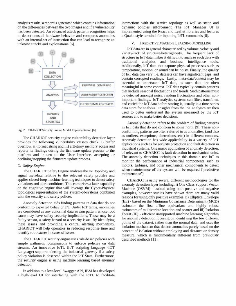
analysis results, a report is generated which contains information on the differences between the two images and if a vulnerability has been detected. An advanced attack pattern recognition helps to detect unusual hardware behavior and compares anomalies with an internal set of instruction that can lead to recognize an unknow attacks and exploitations [6].
Fig. 2. CHARIOT Security Engine Model Implementation [6]
The CHARIOT security engine vulnerability detection layer provides the following vulnerability classes check: i) buffer overflow, ii) format string and iii) artbitrary memory access and reports its findings during the firmware update process to the platform and in-turn to the User Interface, accepting or declining/stopping the firmware update process.
C. Safety Engine
The CHARIOT Safety Engine analyses the IoT topology and signal metadata relative to the relevant safety profiles and applies closed-loop machine-learning techniques to detect safety violations and alert conditions. This comprises a later capability on the cognitive engine that will leverage the Cyber-Physical topological representation of the system-of-systems combined with the security and safety polices.
Anomaly detection aids finding patterns in data that do not conform to expected behavior [7]. Under IoT terms, anomalies are considered as any abnormal data stream pattern whose root cause may have safety security implications. These may be a faulty sensor, a safety hazard or a security issue. By identifying these issues and providing a central alerting mechanism, CHARIOT will help operators in reducing response time and identify root causes in cases of issues.
The CHARIOT security engine uses rule-based policies with simple arithmetic comparisons to enforce policies on data streams. An innovative IoTL (IoT scripting language -IOT Language) supports alerting the industrial gateway if a safety policy violation is observed within the IoT State. Furthermore, the security engine is using machine learning based anomaly detection.
In addition to a low-level Swagger API, IBM has developed a high-level UI for interfacing with the IoTL to facilitate
interactions with the service topology as well as static and dynamic policies enforcement. The IoT Manager UI is implemented using the React and Leaflet libraries and features a Quake-style terminal for inputting IoTL commands [8].
V. PREDICTIVE MACHINE LEARNING MODELLING
IoT data are in general characterized by volume, velocity and variety-lack of structure/heterogeneity. The frequent lack of structure in IoT data makes it difficult to analyze such data with traditional analytics and business intelligence tools. Additionally, IoT data that capture physical processes such as temperature, motion, or sound can be noisy. Finally, the quality of IoT data can vary, i.e. datasets can have significant gaps, and contain corrupted readings. Lastly, meta-data/context may be essential to understand IoT data, as such data are often meaningful in some context. IoT data typically contain patterns that include seasonal fluctuations and trends. Such patterns must be detected amongst noise, random fluctuations and other non-important findings. IoT analytics systems can filter, transform, and enrich the IoT data before storing it, usually in a time-series data store for analysis. Insights from the IoT analytics are then used to better understand the system measured by the IoT sensors and to make better decisions.
Anomaly detection refers to the problem of finding patterns in IoT data that do not conform to some norm [9]. These non-conforming patterns are often referred to as anomalies, (and also as outliers, exceptions, aberrations, etc.) in different contexts. Anomaly detection has wide applicability in a variety of IoT applications such as for security protection and fault detection in industrial systems. One major application of anomaly detection, of relevant to CHARIOT is fault detection in mechanical units. The anomaly detection techniques in this domain use IoT to monitor the performance of industrial components such as motors, turbines, and other mechanical components to detect when maintenance of the system will be required (‘predictive maintenance’).
CHARIOT is using several different methodologies for the anomaly detection layer including: i) One Class Support Vector Machine (OSVM) - trained using both positive and negative examples, however studies have shown there are many valid reasons for using only positive examples, ii) Elliptical Envelope (EE) - based on the Minimum Covariance Determinant (MCD) estimator the first affine equivariant and highly robust estimators of multivariate location and scatter and iii) Isolation Forest (IF) - efficient unsupported machine learning algorithm for anomaly detection focusing on identifying the few different points of the dataset, rather than the normal data, and uses the isolation mechanism that detects anomalies purely based on the concept of isolation without employing and distance or density measure, which is fundamentally different from previously described methods [11].
15

Fig. 3. Example of Anomaly Detection Modelling
VI. SOFTWARE LIFE-CYCLE MANAGEMENT
The CHARIOT software analysis and lifecycle management includes a software source code verification analysis level (Bismon) that is strongly linked to the CHARIOT security engine (and the firmware update process). This, includes the source code analysis, creation of metadata and hashing of source code inside the binary file that are analysed during the firmware update process (via the security engine and together with the binary level warnings) to either accept or decline the software update process.
CHARIOT focuses mainly on a system of systems (e.g. networks of systems and systems of networks) approach, so [10] “aims to address how safety-critical-systems should be securely and appropriately managed and integrated with a fog network made up of heterogeneous IoT devices and gateways.”. Within CHARIOT, static analysis methods support its Open IoT Cloud Platform through its IoT Privacy, Security and Safety Supervision Engine. Some industrial CHARIOT partners, while being IoT network and hardware experts, acknowledge that their favourite IDE (provided by their main IoT hardware vendor) is running some GCC under the hoods during the build of their firmware. Nevertheless, these partners do not use static source code analysis tools.
The CHARIOT approach to static source analysis leverages on an existing recent GCC cross-compiler [11] so focuses on GCC-compiled languages [12]. Hence, the IoT software developer following the CHARIOT methodology would just add some additional flags to existing gcc or g++ cross-compilation commands, and needs simply to change slightly his/her build automation scripts (e.g. add a few lines to his Makefile). Such a gentle approach (see figure 1) has the advantage of not disturbing much the usual developer workflow and habit, and addresses also the junior IoT software developer. The compilation and linking processes are communicating -via some additional GCC plugins (cf. GCC Community [6] §24) doing inter-process communication- with our persistent
monitor, tentatively called bismon. It is preferable (see Free Software Foundation) to use free software GCC plugins (or free software generators for them) when compiling proprietary firmware with the help of these plugins; otherwise, there might be some licensing issues on the obtained proprietary binary firmware blob, if it was compiled with the help of some hypothetical proprietary GCC plugin.
CHARIOT static analysis tools will leverage on the mainstream GCC compiler (generally used as a cross-compiler for IoT firmware development). Current versions of GCC are capable of quite surprising optimizations (internally based upon some sophisticated static analysis techniques and advanced heuristics). But to provide such clever optimizations, the GCC compiler has to be quite a large software, of more than 5.28 million lines of source code (in gcc-8.2.0, measured by sloccount). This figure is an under-estimation, since GCC contains a dozen of domain specific languages and their transpilers to generated C++ code, which are not well recognized or measured by sloccount.
Since a single Bismon process is used by a small team of IoT developers, it provides some web interface: each IoT developer will interact with the persistent monitor through his/her web browser. In addition, a static analysis expert (which could perhaps be the very senior IoT developer of the team) will configure the static analysis (also through a web interface) [13].
VII. SUPPORTING BLOCKCHAIN AND PKI TECHNOLOGIES
The blockchain component of CHARIOT (based on a hyperledger Fabric implementation) is used at different engines and layers to affirm data, devices and network information. In this, the information stored in blockchain include sensor IDs, network states and firmware validation hashings. These are used by the privacy, security and safety engine as described before.
Blockchain-based PKI approach makes MITM attacks virtually impossible as when group of authorities publishes or revokes the public key of an identity on the blockchain, the information will be distributed across all nodes, so tampering the public-key will be (theoretically) out of the question. Traditional PKI resolves MITM risks by embedding Root CA certificates into browser installations, thus artificially expanding CA entrance barriers and increasing the time necessary for Root CA certificate revocation.
There are several advantages of using this PKI-based blockchain implementation including: i) The validation of a certificate is simple and fast with no form of CA certificate chain, ii) Blockchain-based PKI solves a longstanding problem of traditional PKIs by not requiring the use of a service that issues certificate revocation lists (CRLs) thanks to blockchain synchronization between network’s nodes where any modification to the state of a certificate will be instantaneously notified to the all nodes and iii) Blockchain-based PKI provides flexible protection against the man-in-the-middle (MITM) attacks. Traditionally, MITM is considered as a major security risk implying attacker to hijack a browser’s connection for a given website by presenting a valid certificate (i.e., forged public key) for that domain. For users and web browsers it is difficult to identify the replacement of certificate when the related CA has been hacked by the attacker [7] [8].
16

VIII. OPERATIONAL AND DEVICE MANAGEMENT
DASHBOARDS
User interfacing is considered as an important layer where two distinct interfaces (dashboards) are being developed (Device Management Dashboard: handling blockchain devices registration, firmware updates, engine management and IoTL interfacing and Operational Dashboard: providing Engines’ health and performance monitoring as well as alerts’ and sensor data visualization).
The device management dashboard is utilizing the latest state-of-the-art web technologies to deliver rich content information to the LL users and achieve cross-browser and multi-device compatibility. Further to that, the dashboard is designed as a user friendly and fully responsive web solution, based on the CHARIOT industrial needs, providing an easy access to the necessary information. Blockchain security and accessing controls are applied to secure the access to specific information and data by different users. Moreover, Dashboards focus not only to standard monitoring actions and providing a visibility on an industrial IoT topology, sensor values and alerts but also to secured (utilizing blockchain technology) managerial activities. Those activities such as authenticating and registering (or unregistering) a sensor in the IoT topology and updating the firmware (of a sensor or a gateway) can be performed by the security engineers and management. It is important to mentioned that during the “firmware update” there is a chain of actions and integration with a number of CHARIOT components.
Fig. 4. Example of Data Management Dashboard
The CHARIOT Operational Dashboard is providing Engines’ health and performance monitoring as well as alerts’ and sensor data visualization. CHARIOT has identified the need of a more sophisticated method for platform performance monitoring as designed following the micro-services software architecture paradigm. After research on the industry-standard of micro-service platform monitoring techniques, CHARIOT has decided to adopt CNCF best practices and deploy Jaeger. With Jaeger, we can trace every action trail at the CHARIOT platform. The analysis of the collected traces helps the developer to identify bottlenecks to improve system performance and find the cause of platform malfunction. In addition to this, we implement service to monitor health of every micro-services by sending a “magic-package” to it and then wait for its response,
in the end the system administrator has a dashboard to view all the collected information [14].
Fig. 5. Example of Operational Dashboard
IX. CHARIOT INDUSTRIAL VALIDATION
CHARIOT is by design driven by industrial IoT requirements following actual needs and paradigms of three sectors: rail, airports and smart buildings. These three industrial cases’ analysis has derived exhaustive sets of requirements, industrial scenarios and validation KPIs on which, CHARIOT, has based its technical implementations.
CHARIOT will be validated in the above three (3) industrial cases based on representative security related scenarios highlighting the value and integrated approach of CHARIOT in solving modern IoT security issues and challenges.
CHARIOT is currently through its deployment and validation phase, having deployed its whole platform in the three infrastructures and having performed its first round of technical recommendations from the end-users. In the next five months, and up to the end of 2020, CHARIOT is expected to finish its activities with the final feedback of recommendations and adaptations to the three industrial setups.
ACKNOWLEDGMENTS
This project has received funding from the European Union’s Horizon 2020 research and innovation program (No 780075). The authors acknowledge the research outcomes of this publication belonging to the CHARIOT consortium.
REFERENCES
[1] K. Loupos - INTEGRATED SOLUTION FOR PRIVACY AND
SECURITY OF IOT DEVICES IN CRITICAL INFRASTRUCTURES,
Critical Infrastructure Protection and Resilience Europe (CIPRE 2020), 6-8 October 2020, Bucharest, Romania.
[2] K. Loupos, A. Papageorgiou, A. Mygiakis, B. Caglayan, B. Karakostas, T. Krousarlis, F. Vedrine, C. Skoufis, S. Christofi, G. Theofilis, H.
Avgoustidis, G. Boulougouris, A. Battaglia, M. Villiani - COGNITIVE
PLATFORM FOR INDUSTRIAL IOT SYSTEM SECURITY, SAFETY AND PRIVACY, Embedded World 2020 Conference and Exhibition, 25 - 27 February 2020, Nuremberg, Germany.
[3] Adel S. Elmaghraby, Michael M. Losavio, “Cyber security challenges in
Smart Cities: Safety, security and privacy”, Journal of Advanced Research Volume 5, Issue 4, pp 491–497, 07/ 2014.
[4] CHARIOT – D3.2 – IoT Privacy Engine based on PKI and Blockchain technologies, CHARIOT 2019.
17

[5] L. Axon and M. Goldsmith, “PB-PKI: A privacy-aware blockchain based
PKI,” in Proceedings of the 14th International Joint Conference on e-
Business and Telecommunications (ICETE 2017) - Volume 4: SECRYPT, Madrid, Spain, July 24-26, 2017., 2017, pp. 311–318.
[6] CHARIOT - D3.8 – IoT Security Engine based on vulnerability checks, CHARIOT 2020.
[7] Chandola, Varun, Arindam Banerjee, and Vipin Kumar. "Anomaly detection: A survey." ACM computing surveys (CSUR) 41.3 (2009): 15.
[8] CHARIOT – D3.9 - IoT Safety Supervision Engine (ISSE) (final prototype) v1.0_FINAL, CHARIOT, 2020.
[9] Chandola, Varun, Arindam Banerjee, Vipin Kumar. Anomaly detection: a survey. ACM Computing Surveys, September 2009.
[10] Taken in October 2018 from https://www.chariotproject.eu/About, §Technical Approach.
[11] The actual version and the concrete configuation of GCC are important; we want to stick -when reasonably possible- to the latest GCC releases,
e.g. to GCC 8 in autumn 2018. In the usual case, that GCC is a cross-
compiler. In the rare case where the IoT system runs on an x86-64 device under Linux, that GCC is not a cross-, but a straight compiler.
[12] The 2019 Gnu Compiler Collection is able to compile code written in C, C++, Objective-C, Fortran, Ada, Go, and/or D.
[13] CHARIOT – D1.5 - Specialized Static Analysis tools for more secure and safer IoT software development (ver.2).
[14] CHARIOT – D6.9 – CHARIOT Rescoping Guideline
18

Copyright © 2020 for this paper by its authors. Use permitted under Creative Commons License Attribution 4.0 International (CC BY 4.0).
Guidelines for Privacy and Security in IoT
Pasquale Annicchino
Archimede Solutions
Geneva, Switzerland
Simone Seminara, Francesco Capparelli
Istituto Italiano per la Privacy e la Valorizzazione dei Dati
Rome, Italy
{s.seminara, f.capparelli}@ istitutoprivacy.eu
Abstract— Norms and standards define the ecosystem in which
IoT solutions are developed and deployed. It is often difficult for
people without a legal training or an understanding of
standardization dynamics to fully grasp the state of the art in this
very relevant field. This contribution aims at highlighting the most
relevant tools available and explaining their relevance.
Keywords— Data protection; privacy; security; Internet of
Things; guide-lines.
I. INTRODUCTION: MAPPING THE LANDSCAPE
A. Relevance of the exercise
The mapping of international security and data protection by
design guidelines is of paramount relevance in the identification
of best practices in the context of IoT. With regard to the
implementation and demonstration of appropriate technical and
organizational measures as referred in Articles 24(1)-(3), 25,
and 32(1)-(3) of the General Data Protection Regulation
(GDPR) [1], the literature on data protection is extensive,
ranging from regulations to privacy-enhancing technologies
and rules that are general. Without any objective of
completeness, which would be outside the scope of this
contribution, we briefly introduce below some of the best-
known approaches to data management and data protection
from a technical perspective (among those freely available
online) which might be useful also for researchers with no
previous legal training.
First of all, the European Union Agency for Cybersecurity
(ENISA) in the eminent document Privacy and Data Protection
by Design [2] declares eight general strategies for implementing
the principle of “privacy by design“ as defined in the GDPR:
minimise, hide, separate, aggregate, inform, control, enforce
and demonstrate.
Another important approach to formulate general principles for
the protection of personal data and cybersecurity is the one
developed by the Information & Privacy Commissioner of the
State of Ontario, Canada. This work [3] proposes seven general
principles: Proactive not Reactive (Preventative not Remedial);
Privacy as the Default Setting; Privacy Embedded into Design;
Full Functionality (Positive-Sum, not Zero-Sum); End-to-End
Security (Full Lifecycle Protection); Visibility and
Transparency (Keep it Open); Respect for User Privacy (Keep
it User-Centric).
It should also be noted that there are several non-legal
frameworks resulting from the application of international
cybersecurity standards and, therefore, the present document is
useful to provide a mapping of the actual international
standards, guidelines and best practices regarding IoT.
B. Regulations
Almost all the articles of the GDPR provide the European
interpretation of the concept of personal data protection,
specifying several rights for citizens with regard to the
processing of their personal data. Rights such as access and
limitation are well detailed in the Regulation, which therefore
gives control over the data primarily to the individual to whom
the data are related. To complement this, there are three articles
referring to cybersecurity, without which data protection would
inevitably be compromised. Article 32 outlines the security
measures, while Articles 33 and 34 the notification obligations
in case of data breach.
In relation to the focus on the IoT systems in this document,
however, it should be noted that the GDPR is not entirely
explicit on how an IoT device should protect data. The
manufacturers are therefore obliged to supply products that
comply with the Regulation and to ensure that the companies
that will (acquire and then) use them can operate in accordance
with the Regulation. Finally, Article 25 outlines provisions on
data protection by design and by default, i.e. already by design
and by default, taking over the concepts outlined in Articles 5
(on “data minimization”) and 32 (on security measures,
mentioning in particular “pseudonymization”). However, it is
completely implicit what characteristics an application must
have in order to be considered GDPR-compliant.
The processing of personal data within the IoT framework often
sees the interaction between the system and its operator, the
latter being authorised to the specific processing possible
through the use of the given IoT device. In particular, the
authorisation to the processing – as mandated by the GDPR –
details the areas of the processing itself, i.e. what and how the
authorised person is allowed to process personal data. There is
then a so-called ceremony between device and operator, i.e. a
protocol distributed and enacted between machines and human
beings. Sometimes such a protocol may involve several persons
or even none: the GDPR defines the latter case as automated
processing.
The articles of the GDPR can be interpreted as a set of
requirements, aimed at achieving the general objective of
personal data protection, for the participants in the
ceremony/protocol mentioned above.
This work has been partially supported by NGIoT [52], a Coordination and
Support Action funded by European Union’s Horizon 2020 research and innovation programme (H2020-EU.2.1.1.) under grant agreement ID
825082.
19

II. RELEVANT GUIDELINES
In this paragraph we detail general guidelines, reviews and
mappings which can be applied to the world of the Internet of
Things as a whole. Each subsection details one of the
organisations involved in such publications.
A. OWASP
The Open Web Application Security Project (OWASP) [4] is a
nonprofit foundation that works to improve the security of
software through its community-led open source software
projects. One of its flagship projects is the OWASP Top 10 [5],
a standard awareness document for developers and web
application security; it represents a broad consensus about the
most critical security risks to web applications.
Here are two of its publications about IoT.
1) OWASP IoT Top 10, 2018 (previous version in 2014)
Along the lines of the widely known Top 10 for web apps, the
OWASP IoT Top 10 [6] focuses on things to avoid when
building, deploying or managing IoT systems. The list is:
1) Weak, Guessable, or Hardcoded Passwords. Use of easily
brute forced, publicly available, or unchangeable
credentials, including backdoors in firmware or client
software that grants unauthorised access to deployed
systems.
2) Insecure Network Services. Unneeded or insecure network
services running on the device itself, especially those
exposed to the internet, that compromise the
confidentiality, integrity/authenticity, or availability of
information or allow unauthorised remote control.
3) Insecure Ecosystem Interfaces. Insecure web, backend API,
cloud, or mobile interfaces in the ecosystem outside of the
device that allows compromise of the device or its related
components. Common issues include a lack of
authentication/authorization, lacking or weak encryption,
and a lack of input and output filtering.
4) Lack of Secure Update Mechanism. Lack of ability to
securely update the device. This includes lack of firmware
validation on device, lack of secure delivery (un-encrypted
in transit), lack of anti-rollback mechanisms, and lack of
notifications of security changes due to updates.
5) Use of Insecure or Outdated Components. Use of
deprecated or insecure software components/libraries that
could allow the device to be compromised. This includes
insecure customization of operating system platforms, and
the use of third-party software or hardware components
from a compromised supply chain.
6) Insufficient Privacy Protection. User’s personal
information stored on the device or in the ecosystem that is
used insecurely, improperly, or without permission.
7) Insecure Data Transfer and Storage. Lack of encryption or
access control of sensitive data anywhere within the
ecosystem, including at rest, in transit, or during
processing.
8) Lack of Device Management. Lack of security support on
devices deployed in production, including asset
management, update management, secure
decommissioning, systems monitoring, and response
capabilities.
9) Insecure Default Settings. Devices or systems shipped with
insecure default settings or lack the ability to make the
system more secure by restricting operators from
modifying configurations.
10) Lack of Physical Hardening. Lack of physical hardening
measures, allowing potential attackers to gain sensitive
information that can help in a future remote attack or take
local control of the device.
2) OWASP IoT Top 10 2018 Mapping Project
This project [7] provides mappings of the OWASP IoT Top 10
2018 [6] to industry publications and sister projects, such as:
• OWASP IoT Top 10, previous version (2014) [8];
• GSMA IoT Security Assessment Checklist [9] (see also §
2.3.2);
• Department for Digital, Culture, Media & Sport (UK
Government), Code of Practice for Consumer IoT Security
[10] (see § 2.2.1);
• ENISA Baseline Security Recommendations for IoT in the
context of Critical Information Infrastructures, 20 November
2017 [11] (see § 2.4.1);
• CTIA Cyber-security Certification Test Plan for IoT Devices
[12][13] (see § 2.5);
• CSA IoT Security Controls Framework [14][15] (see § 2.5);
• ETSI Technical Specification (TS) 103 645 V1.1.1 (2019-
02), CYBER; Cyber Security for Consumer Internet of
Things [16].
Since this Mapping Project, ETSI published an updated version
of the above standard [17] and its European counterpart [18].
From this starting point, in the following subsections we will
explore these publications.
B. UK Government, Department for Digital, Culture, Media
& Sport
The Department for Digital, Culture, Media & Sport (DCMS)
[19] helps to drive growth, enrich lives and promote Britain
abroad. Among other activities, the DCMS commissioned the
PETRAS IoT Research Hub [20], a consortium of universities
and research institutions that work together to explore critical
issues in privacy, ethics, trust, reliability, acceptability and
security of the IoT to conduct two literature reviews: on
industry recommendations for government to improve IoT
security; on the current international developments around IoT
security. The two aims to these reviews, jointly published in
[21], were to identify the key themes emerging from the
literature and to identify international consensus around core
Security by Design principles for the IoT.
1) Code of Practice for Consumer IoT Security, 14 October
2018
The DCMS, in conjunction with the UK National Cyber
Security Centre (NCSC) [22] and following engagement with
industry, consumer associations and academia, has developed
this Code of Practice [10] (see § 2.1.2) to support all parties
involved in the development, manufacturing and retail of
20

consumer IoT with a set of guidelines to ensure that products
are secure by design and to make it easier for people to stay
secure in a digital world. The Code of Practice brings together,
in thirteen outcome-focused guidelines, what is widely
considered good practice in IoT security. The Code was first
published in draft in March 2018 as part of the Secure by Design
collection of reports [23].
An indication is given for each guideline as to which
stakeholder is primarily responsible for implementation.
Stakeholders are defined as Device Manufacturers, IoT Service
Providers, Mobile Application Developers and Retailers. The
thirteen guidelines are:
1) No default passwords. All IoT device passwords shall be
unique and not resettable to any universal factory default
value.
2) Implement a vulnerability disclosure policy. All companies
that provide internet-connected devices and services shall
provide a public point of contact as part of a vulnerability
disclosure policy in order that security researchers and
others are able to report issues. Disclosed vulnerabilities
should be acted on in a timely manner.
3) Keep software updated. Software components in internet-
connected devices should be securely updateable. Updates
shall be timely and should not impact on the functioning of
the device. An end-of-life policy shall be published for end-
point devices which explicitly states the minimum length of
time for which a device will receive software updates and
the reasons for the length of the support period. The need
for each update should be made clear to consumers and an
update should be easy to implement. For constrained
devices that cannot physically be updated, the product
should be isolatable and replaceable.
4) Securely store credentials and security-sensitive data. Any
credentials shall be stored securely within services and on
devices. Hard-coded credentials in device software are not
acceptable.
5) Communicate securely. Security-sensitive data, including
any remote management and control, should be encrypted
in transit, appropriate to the properties of the technology
and usage. All keys should be managed securely.
6) Minimise exposed attack surfaces. All devices and services
should operate on the ‘principle of least privilege’; unused
ports should be closed, hardware should not unnecessarily
expose access, services should not be available if they are
not used and code should be minimised to the functionality
necessary for the service to operate. Software should run
with appropriate privileges, taking account of both security
and functionality.
7) Ensure software integrity. Software on IoT devices should
be verified using secure boot mechanisms. If an
unauthorised change is detected, the device should alert the
consumer/administrator to an issue and should not connect
to wider networks than those necessary to perform the
alerting function.
8) Ensure that personal data is protected. Where devices
and/or services process personal data, they shall do so in
accordance with applicable data protection law, such as the
GDPR. Device manufacturers and IoT service providers
shall provide consumers with clear and transparent
information about how their data is being used, by whom,
and for what purposes, for each device and service. This
also applies to any third parties that may be involved
(including advertisers). Where personal data is processed
on the basis of consumers’ consent, this shall be validly and
lawfully obtained, with those consumers being given the
opportunity to withdraw it at any time.
9) Make systems resilient to outages. Resilience should be
built in to IoT devices and services where required by their
usage or by other relying systems, taking into account the
possibility of outages of data networks and power. As far
as reasonably possible, IoT services should remain
operating and locally functional in the case of a loss of
network and should recover cleanly in the case of
restoration of a loss of power. Devices should be able to
return to a network in a sensible state and in an orderly
fashion, rather than in a massive scale reconnect.
10) Monitor system telemetry data. If telemetry data is
collected from IoT devices and services, such as usage and
measurement data, it should be monitored for security
anomalies.
11) Make it easy for consumers to delete personal data.
Devices and services should be configured such that
personal data can easily be removed from them when there
is a transfer of ownership, when the consumer wishes to
delete it and/or when the consumer wishes to dispose of the
device. Consumers should be given clear instructions on
how to delete their personal data.
12) Make installation and maintenance of devices easy.
Installation and maintenance of IoT devices should employ
minimal steps and should follow security best practice on
usability. Consumers should also be provided with
guidance on how to securely set up their device.
13) Validate input data. Data input via user interfaces and
transferred via application programming interfaces (APIs)
or between networks in services and devices shall be
validated.
2) Mapping of IoT Security Recommendations, Guidance
and Standards to the UK’s Code of Practice for Consumer IoT
Security, 14 October 2018
This document [24], and the open data files and graphs provided
in its companion website [25], maps the Code of Practice for
Consumer IoT Security against published standards,
recommendations and guidance on IoT security and privacy
from around the world. Around 100 documents were reviewed
from nearly 50 organizations. Whilst not exhaustive, it
represents one of the largest collections of guidance available
to date in this area.
The purpose of the mapping is to serve as a reference and tool
for users of the Code of Practice. Manufacturers and other
organisations are already implementing a range of standards,
recommendations and guidance and will seek to understand the
relationship between the Code of Practice and existing material
from industry and other interested parties.
21

C. GSMA
The GSM Association (GSMA) [26] represents the interests of mobile operators worldwide, uniting more than 750 operators with almost 400 companies in the broader mobile ecosystem, including handset and device makers, software companies, equipment providers and internet companies, as well as organisations in adjacent industry sectors.
1) GSMA IoT Security Guidelines, version 2.2, 29 February
2020
The goal of the Internet of Things Security Guidelines
document set [27][28][29][30] is to provide the implementer of
an IoT technology or service with a set of design guidelines for
building a secure product. The set of guideline documents
promotes a methodology for developing secure IoT Services to
ensure security best practices are implemented throughout the
life cycle of the service. The documents provide
recommendations on how to mitigate common security threats
and weaknesses within IoT Services.
2) GSMA IoT Security Assessment
The GSMA IoT Security Assessment [31][32] (see § 2.1.2)
provides a flexible framework that addresses the diversity of the
IoT market, enabling companies to build secure IoT devices and
solutions as laid out in the GSMA IoT Security Guidelines (see
§ 2.3.1), a comprehensive set of best practices promoting the
secure end-to-end design, development and deployment of IoT
solutions.
D. ENISA
The European Union Agency for Cybersecurity [33] has been
working to make Europe cyber secure since 2004. The Agency
works closely together with Members States and other
stakeholders to deliver advice and solutions as well as
improving their cybersecurity capabilities. It also supports the
development of a cooperative response to large-scale cross-
border cybersecurity incidents or crises and since 2019, it has
been drawing up cybersecurity certification schemes.
1) ENISA Good practices for IoT and Smart Infrastructures
Tool
This website [34] intends to provide an aggregated view of the
ENISA Good Practices for IoT and Smart Infrastructure [35]
that have been published the last years. This link comprises the
above-mentioned Baseline Security Recommendations for IoT
in the context of Critical Information Infrastructures [11] (see
§ 2.1.2) and then other publications about cars, hospitals,
airports, public transport and Industry 4.0.
E. Other sources and references
In this subsection we mention other miscellaneous sources
about privacy and security in IoT.
CTIA [36] represents the U.S. wireless communications
industry and companies throughout the mobile ecosystem and
has organised a certification programme for the cybersecurity
of IoT devices [12, 13] (see § 2.1.2).
The Cloud Security Alliance (CSA) [37] is an organization
dedicated to defining and raising awareness of best practices to
help ensure a secure cloud computing environment, including
the Internet of Things with specific security controls [14, 15]
(see § 2.1.2).
The Internet of Things Security Foundation (IoTSF) [38] is a
collaborative, nonprofit, international response to the complex
challenges posed by cybersecurity in the expansive hyper-
connected IoT world. Among its publications, listed in [39], we
can cite [40][41].
The World Wide Web Consortium (W3C) [42] is an
international community that develops open standards to ensure
the long-term growth of the Web. It is led by Tim Berners-Lee,
the inventor of the Web. Its Web of Things (WoT) section [43]
seeks to counter the fragmentation of the IoT through standard
complementing building blocks (e.g. metadata and APIs) that
enable easy integration across IoT platforms and application
domains; to date, two W3C Recommendations have been
published about WoT [44][45].
Of course, international standards developing organisations
(SDOs) – whose members are governmental bodies, agencies or
committees, one per member economy – have published IoT-
related standards. We can cite the ITU-T Y.4000 series from the
International Telecommunication Union (ITU) [46][47] and a
few of those jointly published by the International Organization
for Standardization (ISO) and the International Electrotechnical
Commission (IEC) [48][49][50].
Lastly, we show a glimpse of other relevant international
standards, under development or just finished. This list is taken
from the outcome of the 2020-04-10 webinar Integrating
privacy in the IoT ecosystem [51], organised by the Horizon
2020 project Next Generation Internet of Things (NGIoT) [52],
with the participation of Antonio Kung:
• ISO/IEC TR 20547-1, Information technology — Big data
reference architecture — Part 1: Framework and
application process, first edition published August 2020
• ISO/IEC TR 20547-2:2018, Information technology — Big
data reference architecture — Part 2: Use cases and derived
requirements, first edition published January 2018
• ISO/IEC 20547-3:2020, Information technology — Big data
reference architecture — Part 3: Reference architecture,
first edition published March 2020
• ISO/IEC 20547-4, Information technology — Big data
reference architecture — Part 4: Security and privacy, first
edition published September 2020
• ISO/IEC TR 20547-5:2018, Information technology — Big
data reference architecture — Part 5: Standards roadmap,
first edition published February 2018
• ISO/IEC CD 23751, Information technology — Cloud
computing and distributed platforms — Data sharing
agreement (DSA) framework
• ISO/IEC CD 27400.2, Cybersecurity – IoT security and
privacy – Guidelines (formerly known as ISO/IEC CD
27030, Information technology — Security techniques —
Guidelines for security and privacy in Internet of Things
(IoT))
• ISO/IEC CD TS 27101, Information technology — Security
techniques — Cybersecurity — Framework development
guidelines
22

• ISO/IEC CD 27556, Information technology — User-centric
framework for the handling of personally identifiable
information (PII) based on privacy preferences
• ISO/IEC WD 27557, Organizational privacy risk
management
• ISO/IEC WD TS 27560, Privacy technologies — Consent
record information structure
• ISO/IEC AWI 30149, Internet of things (IoT) —
Trustworthiness framework
• ISO/AWI 31700, Consumer protection — Privacy by design
for consumer goods and services
III. CONCLUSION
Guidelines are important tools for different stakeholders involved in the deployment of IoT solutions. They offer key basic points and requirements to enhance the trust of end-users and facilitate deployment. The documents highlighted in this contribution show that an important amount of work has been already done by several organisations and deserves to be taken into account.
Following the recommendations provided by the mapped international standards, therefore, allows to respect the principles of the GDPR: for example, the international standards referred to the development phase are useful to respect the “privacy by design” principle set in Article 25 GDPR; the standards on the security of personal data processing are functional to the respect of Article 32 GDPR.
As a side note, the application of the principles of the GDPR is not sufficient in cases where such processing of personal data should concern Law Enforcement Agencies (LEAs). According to the provisions of Article 29 of Directive (EU) 2016/680 [53], in fact, the data controller may use an accountability mechanism in the evaluation and adoption of technical-organisational measures. In any case, the aforementioned measures must be suitable to guarantee an adequate level of security in order to avoid the risk of personal data violation.
In general, it is useful to use all international standards as guidelines and to deduce the best practices necessary to achieve a level of security that can generate trust in end-users and simultaneously achieve compliance with the main regulations. All the mapping efforts across different security controls and publications show that the amount of redundancies is very high: we can then state that a consensus, a “common sense” has emerged in the field of IoT cybersecurity and privacy. Moreover, from a broader perspective, we can say that IoT security measures overlap consistently with cybersecurity frameworks and standards already in place for “traditional computing”: consider, for instance, ISO/IEC 27001:2013 [54] and the Common Criteria for Information Technology Security Evaluation [55][56][57][58][59][60].
It is paramount at legislation level to properly address the need to go beyond what the GDPR and the NISD (Network and Information Security Directive) [61] today represent. With the progress of technology, is obvious that lawmakers have the duty to follow rapidly the new challenges that arise from the evolution in the societal and economic global landscape. In this sense, the integration of IoT in homes, cities and industries gives the
legislators the opportunity (or necessity?) to build a new legal framework to comply with ethical requirements, to better protect freedoms and rights of citizens, at an increasingly supranational and intergovernmental level. A “GDPR of Things” is therefore urgent, with an expanded scope from previous laws, in order to establish stricter rules and norms for information security and personal data protection in World that moves fast towards “ubiquitous computing” (IoT, 5G, wearables, etc.).
In parallel with new legislative frameworks, it would be preferable a consolidation of standards and best practices carried forward by SDOs and the private sector in an open and interoperable way, before the proliferation of “walled gardens” that may compromise freedoms and rights of citizens worldwide.
REFERENCES
[1] Regulation (EU) 2016/679 of the European Parliament and of the Council of 27 April 2016 on the protection of natural persons with regard to the processing of per-sonal data and on the free movement of such data, and repealing Directive 95/46/EC (General Data Protection Regulation) (Text with EEA relevance); current consoli-dated version (2016-05-04) available at https://eur-lex.europa.eu/eli/reg/2016/679/2016-05-04
[2] European Union Agency for Cybersecurity (ENISA), Privacy and Data Protection by Design – from policy to en-gineering, 12 January 2015; PDF available at https://www.enisa.europa.eu/publications/privacy-and-data-protection-by-design/
[3] Information & Privacy Commissioner (Ontario, Cana-da), Ann Cavoukian, The 7 Foundational Principles. Im-plementation and Mapping of Fair Information Practices; PDF available at https://www.ipc.on.ca/wp-content/uploads/Resources/pbd-implement-7found-principles.pdf
[4] OWASP Foundation, Inc.; https://owasp.org/
[5] OWASP Top 10; https://owasp.org/www-project-top-ten/
[6] OWASP IoT Top 10, 2018; https://wiki.owasp.org/index.php/OWASP_Internet_of_Things_Project#tab=IoT_Top_10
[7] OWASP IoT Top 10 2018 Mapping Project; https://scriptingxss.gitbook.io/owasp-iot-top-10-mapping-project/ and https://wiki.owasp.org/index.php/OWASP_Internet_of_Things_Project#tab=OWASP_IoT_Top_10_2018_Mapping_Project
[8] OWASP IoT Top 10, 2018; https://wiki.owasp.org/index.php/Top_10_IoT_Vulnerabilities_(2014)
[9] https://www.gsma.com/security/resources/clp-17-gsma-iot-security-assessment-checklist-v3-0/
[10] https://www.gov.uk/government/publications/code-of-practice-for-consumer-iot-security/
[11] https://www.enisa.europa.eu/publications/baseline-security-recommendations-for-iot/
[12] CTIA, IoT Cybersecurity Certification Program Manage-ment Document, version 1.1, May 2019; PDF available at https://api.ctia.org/wp-con-tent/uploads/2019/05/ctia_IoT_cybersecurity_pmd_ver-1_1.pdf
[13] CTIA, IoT Cybersecurity Certification FAQ, version 1.0, 28 March 2019; PDF available at https://api.ctia.org/wp-content/uploads/2019/03/CTIA-Certification-FAQ-Ver-1.0-28-March-2019.pdf
[14] CSA, IoT Security Controls Framework, 5 March 2019; https://cloudsecurityalliance.org/artifacts/iot-security-controls-framework/
[15] CSA, Guide to the IoT Security Controls Framework, 5 March 2019; https://cloudsecurityalliance.org/artifacts/guide-to-the-iot-security-controls-framework/
[16] https://www.etsi.org/deliver/etsi_ts/103600_103699/103645/01.01.01_60/ts_103645v010101p.pdf
[17] https://www.etsi.org/deliver/etsi_ts/103600_103699/103645/02.01.02_60/ts_103645v020102p.pdf
[18] ETSI European Standard (EN) 303 645 V2.1.1 (2020-06); https://www.etsi.org/deliver/etsi_en/303600_303699/303645/02.01.01_60/en_303645v020101p.pdf
23

[19] https://www.gov.uk/government/organisations/department-for-digital-culture-media-sport/
[20] https://petras-iot.org/
[21] PETRAS IoT Hub, Summary literature review of industry recommendations and international developments on IoT se-curity, 7 March 2018; https://www.gov.uk/government/publications/summary-literature-review-on-iot-security/
[22] https://www.ncsc.gov.uk/
[23] https://www.gov.uk/government/collections/secure-by-design/
[24] https://www.gov.uk/government/publications/mapping-of-iot-security-recommendations-guidance-and-standards/
[25] Copper Horse Ltd. on behalf of DCMS, Mapping Securi-ty & Privacy in the Internet of Things; https://iotsecuritymapping.uk/
[26] GSM Association; https://www.gsma.com/
[27] GSMA, IoT Security Guidelines Overview Document; https://www.gsma.com/iot/iot-security-guidelines-overview-document/
[28] GSMA, IoT Security Guidelines for IoT Service Ecosystem; https://www.gsma.com/iot/iot-security-guidelines-for-iot-service-ecosystem/
[29] GSMA, IoT Security Guidelines Endpoint Ecosystem; https://www.gsma.com/iot/iot-security-guidelines-for-endpoint-ecosystem/
[30] GSMA, IoT Security Guidelines for Network Operators; https://www.gsma.com/iot/iot-security-guidelines-for-network-operators/
[31] GSMA, IoT Security Assessment Checklist, version 3.0, 30 September 2018; .zip file available at https://www.gsma.com/iot/iot-security-assessment/
[32] GSMA, IoT Security Assessment Process, version 2.0, 30 September 2018; .zip file available at https://www.gsma.com/iot/iot-security-assessment/
[33] https://www.enisa.europa.eu/
[34] https://www.enisa.europa.eu/topics/iot-and-smart-infrastructures/iot/good-practices-for-iot-and-smart-infrastructures-tool/
[35] https://www.enisa.europa.eu/topics/iot-and-smart-infrastructures/
[36] https://www.ctia.org/
[37] https://cloudsecurityalliance.org/
[38] https://www.iotsecurityfoundation.org/
[39] https://www.iotsecurityfoundation.org/best-practice-guidelines/
[40] IoTSF, IoT Security Compliance Framework, Release 2.1, May 2020; .zip file available at https://www.iotsecurityfoundation.org/wp-content/uploads/2020/05/IoTSF-IoT-Security-Compliance-Framework-Questionnaire-Release-2.1.zip
[41] IoTSF, Mapping the IoT Security Foundation’s Compliance Framework to ETSI TS 103 645 Standard, February 2019; PDF available at https://www.iotsecurityfoundation.org/wp-content/uploads/2019/02/Mapping-the-IoTSF%E2%80%99s-Compliance-Framework-to-ETSI-TS-103-645-Standard.pdf
[42] https://www.w3.org/
[43] https://www.w3.org/WoT/
[44] W3C, Web of Things (WoT) Architecture, W3C Recom-mendation, 9 April 2020; https://www.w3.org/TR/wot-architecture/
[45] W3C, Web of Things (WoT) Thing Description, W3C Rec-ommendation, 9 April 2020 (link errors corrected 23 June 2020); https://www.w3.org/TR/wot-thing-description/
[46] ITU-T Recommendation Y.4000/Y.2060 (approved in 2012-06-15); SERIES Y: GLOBAL INFORMATION INFRASTRUCTURE, INTERNET PROTOCOL ASPECTS AND NEXT-GENERATION NETWORKS; Next Generation Networks – Frameworks and func-tional architecture models; Overview of the Internet of things (former ITU-T Y.2060 renumbered as ITU-T Y.4000 on 2016-02-05 without further modification and without being republished); https://www.itu.int/rec/T-REC-Y.4000
[47] https://www.itu.int/ITU-T/recommendations/index.aspx?ser=Y
[48] ISO/IEC 21823-1:2019, Internet of things (IoT) — Interop-erability for IoT systems — Part 1: Framework, February 2019; https://www.iso.org/standard/71885.html
[49] ISO/IEC 21823-2:2020, Internet of things (IoT) — Interop-erability for IoT systems — Part 2: Transport interoperabil-ity, April 2020; https://www.iso.org/standard/80986.html
[50] ISO/IEC 30141:2018, Internet of Things (loT) — Reference Architecture, first edition published August 2018 (sec-ond edition pending); https://www.iso.org/standard/65695.html
[51] https://www.ngiot.eu/event/ngiot-webinar-integrating-privacy-in-the-iot-ecosystem/
[52] https://cordis.europa.eu/project/id/825082
[53] Directive (EU) 2016/680 of the European Parliament and of the Council of 27 April 2016 on the protection of natural persons with regard to the processing of per-sonal data by competent authorities for the purposes of the prevention, investigation, detection or prosecution of criminal offences or the execution of criminal penal-ties, and on the free movement of such data, and re-pealing Council Framework Decision 2008/977/JHA; current consolidated version (2016-05-04) available at https://eur-lex.europa.eu/eli/dir/2016/680/2016-05-04
[54] ISO/IEC 27001:2013, Information technology — Security techniques — Information security management systems — Requirements; https://www.iso.org/standard/54534.html
[55] ISO/IEC 15408-1:2009, Information technology — Securi-ty techniques — Evaluation criteria for IT security — Part 1: Introduction and general model, December 2009 (cor-rected version January 2014); https://www.iso.org/standard/50341.html
[56] ISO/IEC 15408-2:2008, Information technology — Securi-ty techniques — Evaluation criteria for IT security — Part 2: Security functional components, August 2008 (corrected version May 2011); https://www.iso.org/standard/46414.html
[57] ISO/IEC 15408-3:2008, Information technology — Securi-ty techniques — Evaluation criteria for IT security — Part 3: Security assurance components, August 2008 (corrected version May 2011); https://www.iso.org/standard/46413.html
[58] ISO/IEC DIS 15408-4, Information security, cybersecurity and privacy protection — Evaluation criteria for IT security — Part 4: Framework for the specification of evaluation methods and activities, under development; https://www.iso.org/standard/72913.html
[59] ISO/IEC DIS 15408-5, Information security, cybersecurity and privacy protection — Evaluation criteria for IT security — Part 5: Pre-defined packages of security requirements, under development; https://www.iso.org/standard/72917.html
[60] ISO/IEC 18045:2008, Information technology — Security techniques — Methodology for IT security evaluation, Au-gust 2008 (corrected version January 2014); https://www.iso.org/standard/46412.html
[61] Directive (EU) 2016/1148 of the European Parliament and of the Council of 6 July 2016 concerning measures for a high common level of security of network and in-formation systems across the Union; https://eur-lex.europa.eu/eli/dir/2016/1148/oj
24

Copyright © 2020 for this paper by its authors. Use permitted under Creative Commons License Attribution 4.0 International (CC BY 4.0).
Semantic Models for Network Intrusion Detection
Peter Bednar, Martin Sarnovsky, Pavol Halas
Department of Artificial Inteligence and Cybernetics
Technical University of Kosice
Kosice, Slovakia
{name.surname}@tuke.sk
Abstract—The presented paper describes the design and
validation of the hierarchical intrusion detection system (IDS),
which combines machine learning approach with the knowledge-
based methods. As the knowledge model, we have proposed the
ontology of network attacks, which allow to us decompose
detection and classification of the existing types of attacks or
formalize detection rules for the new types. Designed IDS was
evaluated on a widely used KDD 99 dataset and compared to
similar approaches.
Keywords—ontologies, network security incidents, machine
learning
I. INTRODUCTION
With the extensive usage of the information and communication technologies the number and variety of the security attacks grow. This is also reflected in the growing of budget invested by companies or public institutions into the security. In order to cope with the current situation, the new and innovative techniques are applied in order to automatize the security management [1].
Recently, we can observe two main approaches to the security of the ICT: the first approach is data-oriented, and it is based on the application of machine learning techniques to proactively achieve the best possible prediction of the new attacks [2][3][4][5]. The second approach is more user-centric and it is based on the application of knowledge modelling techniques in order to model user behavior and ICT environment [8][9][10].
The presented article tries to combine these two approaches into a single system, where the domain knowledge about the types, effects and severity of the attacks is used to decompose intrusion detection task into the classification subtasks which can be handled more efficiently with less training data. The design of the proposed intrusion detection system is symmetrical in the sense that both approaches (machine learning and knowledge based) are equal and mutually contribute to address the challenges of the detection and prevention of the security threats.
The rest of this paper is organized as follows: in the following chapter we will present hierarchical knowledge model in the form of the ontology which will be used for the decomposition of the detection problem and which will provide additional contextual information. Subsequent part describes implemented machine learning models and how these models are combined with the knowledge in the ontology. Subsequent section then presents the experimental evaluation of the
proposed combined approach. In this chapter we at first define quantitative evaluation metrics and then summarize the performance of the system on the standard benchmark dataset from the KDD Cup competition.
II. HIERARCHICAL KNOWLEDGE-BASED INTRUSION DETECTION
SYSTEM
A. Overall system architecture
The main objective of the proposed architecture is to hierarchically decompose detection and classification of the intrusions according to the types of the attacks. For the decomposition we have proposed the Network Intrusion Ontology which main part is formalized as the taxonomy of attack types. This ontology allows to capture all knowledge related to the known types of the attacks, including the description of rare cases which are difficult to detect using the machine learning methods.
The main decomposition of the detection and classification process can be divided into the following phases:
1. Coarse attack/normal classification - this phase is implemented using the machine learning algorithm which distinguish normal traffic and attacks. If a network connection is labelled as a normal one, then an alarm is not raised. Otherwise, the suspicious connection is processed by a set of models to determine the class of attack during the phase 2.
2. Attack class and type prediction—this phase is guided by the taxonomy of the attacks from the Network Intrusion Ontology. The system hierarchically processes the taxonomy and selects the appropriate model to classify the instance on a particular level of a class hierarchy. The model can be a machine learning model statistically inferred from the training data, or rule-based model formalized using the classes and relations from the ontology.
3. When a class of attack is predicted, ontology is queried for all relevant sub-types of the attack type and to retrieve the suitable model to predict the particular sub-type. Knowledge model can also be used to extract specific domain-related information as a new attribute, which could be used either to improve the classifier’s performance or to provide context, domain-specific information which could complement the predictive model.
25

The details about the predictive models and their evaluation will be presented in the subsequent chapter.
B. Network Intrusion Ontology
The proposed knowledge model captures all essentials concepts required to describe network intrusion systems. We have designed our semantic model according to the methodology proposed by Grüninger and Fox and with some extensions from Methodology.
The designed ontology is formalized using the OWL 2 RL profile, which allows to formalize common constructs such as multiple hierarchies and at the same time provides compatibility with the rule languages for automatic reasoning. As the objective of the knowledge model was to use it in the data analytical tasks, the concepts and properties map directly to the data used in the process. Moreover, ontology was extended with the concepts related to the classification models, to create the relation between the particular classifier and its usability on the specific level of target attribute hierarchy. The main classes of ontology include:
• Connections - This class represents the status of each connection record. It specifies Attack connection or normal traffic. Attack connections are further conceptualized using the Attack hierarchy described below.
• Effects - This class contains subclasses that represent all possible consequences of individual attacks (e.g., slows down server response, execute commands as root, etc.).
• Mechanisms - The subclasses represent all possible causes of individual ontology attacks (poor environment sanitation, misconfiguration, etc.).
• Flags - The subclasses represent normal or error states of individual connections (Established, responder aborted, Connection attempt was rejected, etc.). Each of these subclasses has a 1 equivalent instance.
• Protocols - The class contains subclasses that represent the types of the communication protocols on which the connection is running (TCP, UDP, and ICMP).
• Services - The subclasses represent each type of connection service (http, telnet, etc. ...). Each of these subclasses has a 1 equivalent instance.
• Severities - This class represents the severity of the attack, its subclasses represent the severity level (weak, medium, and high).
• Targets - The subclasses represent possible targets of a given type of attack (user, network).
• Models concept covers the classification models used to predict the given target attribute.
The instances of the specified classes represent the network connections (e.g., connection records from the data set). Trained and serialized classification models are instantiated as the instances of the Model class. The models are represented as the web resources and they could be accessed by their URI property, which points to the location where the model is serialized in the
system. The main concepts and relations of the ontology are represented on the Figure 1.
The central part of the proposed semantic model is the taxonomy of Attacks which are summarized in the following figure. The taxonomy was extracted from the types of the attacks described in the KDD 99 datasets. Attacks are divided into the four main groups such as DOS, R2L, U2R and PROBE. The main types of the attacks are further specified on the additional level of the hierarchy.
Fig. 1. The main concepts of the proposed sematnic model.
Fig. 2. The hierarchy of Attacks.
C. Machine learning models
To evaluate the proposed approach, we used the KDD Cup 1999 competition dataset, which is a commonly accepted benchmark for the intrusion detection task. The dataset consists of the records from the device logs in a LAN network collected over nine weeks. For the evaluation, we have used 10% sample with the 494,021 records in total. Each record is labeled as the normal communication or it is assigned to the major attack class and specific attack types. There are 22 different attack types which corresponds to the classes in the proposed ontology.
The common problem with the diagnostic tasks such as intrusion detection systems is that the target attribute (i.e. in our case type of the attack) is highly unbalanced with the majority of normal communication. Table I presents the taxonomy of attack types together with the number of cases in the dataset. Some attack classes such as Probe are more balanced but generally for each attack class we can find some minor types with only the few training examples. The lack of cases is
26

problematic not only for the training of statistical models but also for the evaluation. On the other side, rare cases can be still very critical and can in overall a big impact on the security of the system.
TABLE I. ATTACK TYPES AND NUMBER OF SAMPLES
Attack Attack class # of samples
back
DoS
2203
land 21
neptune 107,201
pod 264
smurf 280,790
teardrop 979
satan
Probe
1589
ipsweap 1247
nmap 231
portsweep 1040
guess_passwd
R2L
53
ftp_write 8
imap 12
phf 4
multihop 7
warezmaster 20
warezclient 1020
spy 2
buffer_overflow
U2R
30
loadmodule 9
perl 3
rootkit 10
normal Normal 97,227
The records for each connection are described by set of features, which are represented in the ontology as the data attributes. The features can be divided into the basic features, content features and traffic features. Overall there are 32 features. The first group describes the type of the communication protocol, duration of the connection, service on the destination network node and other standard attributes describing the TCP connection. Content features are attributes that can be linked to the domain specific knowledge depending on the applications and environment in which communication occurs. The last group of features (traffic) describe the communication attributes captured during the 2 seconds time window, e.g. the number of hosts communicating with the target host etc. For the data preprocessing, we have selected only the most relevant features
for the classification which were identified in the work of [4]. The final list of features includes: service, src_bytes, dst_bytes, logged_in, num_file_creations, srv_diff_host_rate, dst_host_count, dst_host_diff_srv_rate, dst_host_srv_diff_host_rate, srv_count, serror_rate, rerror_rate,
Since the data of diagnostic tasks are commonly highly unbalanced towards the normal cases, the proposed approach is based on the decomposition of the diagnostic classification task into the hierarchy of classifiers. At the top level of the class hierarchy, an attack detection model is used for the prediction to distinguish between the attack connections and normal traffic. The classifier on this level was trained on the whole dataset and target attribute was transformed to the binary indicator. The main goal of this top-level classifier is to reliably separate normal connections from the attack ones.
If the top-level model detects an attack connection, the cases are further classified by the ensemble models into the one of the four types of the attack on the second level of the taxonomy (DoS, R2L, U2R, Probe). In this level, we use ensemble classifier with voting scheme trained on all attack instances (i.e. without the normal communication cases). We found that the proposed ensemble model is more efficient in the case of unbalanced target classes. The standard machine learning models proposed in the previous works were able to gain good accuracy, achieved mostly on the dominant class (in our case on KDD 99 dataset, on the most common DoS attack). However, the simple models struggled to predict minor classes such as U2R, which can be even more serious from the point of view of network security. For example, when training a decision tree model, the model has very good performance for the DoS and R2L classes but missed a significant amount of the Probe attacks and was not able to detect the U2R class at all.
Proposed weighting schema is based on the idea of complementing classifiers which is based on the performance of a particular model on the particular class. This weighting schema is presented on the Table II. The wi,j terms represent the weight associated with the i-th model and j-th class.
TABLE II. WEIGHTING SCHEME OF THE ENSEMBLE MODEL
Model DoS R2L U2R Probe
model 1 w1,1 w2,1 w3,1 w4,1
model 2 w1,2 w2,2 w3,2 w4,2
model 3 w1,3 w2,3 w3,3 w4,3
... ... ... ... ...
After the binary classification and classification of the attack class by ensemble weighted classifier, we have trained particular models to further classify specific type of the attack on the most specific level of the taxonomy. Four different models were trained using only the records of particular attack classes (i.e. models for DoS, R2L, U2R and Probe). The most problematic was minority U2R class, as the dataset contains very few records of that type. The final implemented classification schema is presented on the Figure 3. All models were implemented in the Python environment using the standard pandas and scikit-learn
27
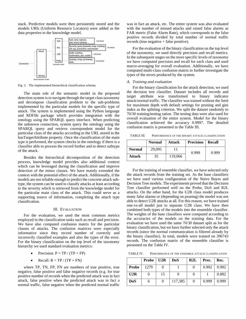
stack. Predictive models were then persistently stored and the models URIs (Uniform Resource Locators) were added as the data properties to the knowledge model.
Fig. 3. The implemented hierarchical classification schema.
The main role of the semantic model in the proposed detection system is to navigate through the target class taxonomy and decompose classification problem to the sub-problems implemented by the particular models for the specific type of attack. The system is implemented using the Python language and RDFlib package which provides integration with the ontology using the SPARQL query interface. When predicting the unknown connection, system query the ontology using the SPARQL query and retrieve correspondent model for the particular class of the attacks according to the URL stored in the hasTargetAttribute property. Once the classification of the main type is performed, the system checks in the ontology if there is a classifier able to process the record further and to detect subtype of the attack.
Besides the hierarchical decomposition of the detection process, knowledge model provides also additional context which can be leveraged during the classification and improve detection of the minor classes. We have mainly extended the context with the potential effect of the attack. Additionally, if the models are not reliable enough to predict the concrete attack sub-type, the system can be used to classify attacks at least according to the severity which is retrieved from the knowledge model for the particular main class of the attack. This could serve as a supporting source of information, completing the attach type classification.
III. EVALUATION
For the evaluation, we used the most common metrics employed in the classification tasks such as recall and precision. We have also computed confusion matrix for the particular classes of attacks. The confusion matrices were especially informative since they record number of correctly and incorrectly classified examples and also the types of the error. For the binary classification on the top level of the taxonomy hierarchy we used standard evaluation metrics:
• Precision: P = TP / (TP + FP)
• Recall: R = TP / (TP + FN)
where TP, TN, FP, FN are numbers of true positive, true negative, false positive and false negative records (e.g. for true positive number of records when the predicted attack was in fact attack, false positive when the predicted attack was in fact a normal traffic, false negative when the predicted normal traffic
was in fact an attack, etc. The entire system was also evaluated with the number of missed attacks and raised false alarms as FAR metric (False Alarm Rate), which corresponds to the false positive records divided by total number of normal traffic records (true negative + false positive).
For the evaluation of the binary classification on the top level of the taxonomy, we used directly precision and recall metrics. In the subsequent stages on the more specific levels of taxonomy we have computed precision and recall for each class and used macro-averaging for overall evaluation. Additionally, we have computed multi-class confusion matrix to further investigate the types of the errors produced by the system.
A. Training and evaluation
For the binary classification for the attack detection, we used the decision tree classifier. Dataset includes all records and target attribute was transformed to binary indicator attack/normal traffic. The classifier was trained without the limit for maximum depth with default settings for pruning and gini index as the splitting criterion. We split the dataset randomly to 70/30 training/testing ration. The testing data were also used for overall evaluation of the entire system. Model for the binary classification achieved the accuracy 0.9997. The detailed confusion matrix is presented in the Table III.
TABLE III. PERFORMANCE OF THE BINARY ATTACK CLASSIFICATION
Normal Attack Precision Recall
Normal 29,095 11 0.999 0.999
Attack 35 119,066
For the training of ensemble classifier, we have selected only the attack records from the training set. As the base classifiers we have used various configuration of the Naive Bayes and Decision Tree models. The experiments proved that the Decision Tree classifier performed well on the Probe, DoS and R2L attacks. On the other hand, for the U2R class model produces many false alarms or (depending on pruning) the model was not able to detect U2R attacks at all. For this reason, we have trained one-vs-all model just to separate U2R class. We have then combined both types of the models into the ensemble classifier. The weights of the base classifiers were computed according to the accuracies of the models on the training data. For the evaluation we have used the same 70/30 dataset split as for the binary classification, but we have further selected only the attack records (since the normal communication is filtered already by the binary classifier). In total, models were trained on 396743 records. The confusion matrix of the ensemble classifier is presented on the Table IV.
TABLE IV. PERFORMANCE OF THE ENSEMBLE ATTACK CLASSIFICATION
Probe U2R DoS R2L Prec. Rec.
Probe 1279 0 1 0 0.992 0.992
U2R 0 15 0 0 1 0.882
DoS 6 0 117,385 0 0.999 0.999
28

R2L 4 2 0 331 0.982 1
On the most specific level of the taxonomy, each major attack class has dedicated one model for the further classification of subtypes. The performance of each model was evaluated using the precision and recall macro-averaged for each subtype. The overall performance of the models is summarized in Table V.
TABLE V. PERFORMANCE OF THE SUBTYPE CLASSIFICATION
Probe U2R DoS R2L
Accuracy 0.991 0.937 0.999 0.989
Precision 0.989 0.927 0.999 0.879
Recall 0.989 0.875 0.999 0.833
The overall system with the hierarchical classification was evaluated using the standard precision, recall F-measure and FAR (False Alarm Rate) metrics. Comparison of the proposed system and models published in previous works [4][6][7][11] is presented in Table VI.
TABLE VI. OVERALL PREFORMANCE OF THE SYSTEM
Classifier Acc. Prec. F1 FAR
C4.5 0.969 0.947 0.970 0.005
Random forests 0.964 0.998 0.986 0.025
Forest PA 0.975 0.998 0.998 0.002
Ensemble model 0.976 0.998 0.998 0.001
Our approach 0.998 0.998 0.998 0.001
Additionally, we have computed confusion matrix, which summarizes the performance for each attack class. The confusion matrix is presented in the Table VII.
TABLE VII. CONFUSION MATRIX FOR THE OVERALL PREFORMANCE OF
THE SYSTEM
Probe U2R DoS R2L Normal
Probe 1176 0 5 0 7
U2R 0 15 0 0 5
DoS 4 0 117547 0 1
R2L 3 1 0 346 7
Normal 1 0 3 1 48454
Besides the classification of attack types, we have implemented and also evaluated the classification of the attack severity. To train the severity detector we have used 10 % of KDD 99 dataset with the 70/30 training/testing ratio. The severity classifier was applied complementary to the ensemble
model for the detection of the attack class. Overall achieved performance was 0.999 precision and recall with very good accuracy for the high and low severity. The Table VIII presents the confusion matrix for the severity detection in comparison for each class of the attack.
TABLE VIII. CONFUSION MATRIX FOR THE SEVERITY DETECTION
High Low Medium Prec. Recall
DoS 117695 0 0
0.999 0.999 Probe 443 0 779
R2L 0 346 6
U2R 0 0 20
Medium severity was biased by our model towards the high severity which has the similar effect like the higher false positive rate. Further details and information about the designed model were published in [9].
IV. CONCLUSION AND FUTURE WORK
In this paper we have proposed an approach based on the combination of knowledge based and machine learning methods for intrusion detection. The proposed knowledge model in the form of the ontology is used for the hierarchical decomposition of the detection process according to the types of the attack. This decomposition allows to overcome the problems with the unbalanced training data which are typical for the diagnostic machine learning tasks. By the leveraging of the domain knowledge, our combined approach also provides an additional context which includes for example the effects and severity of the attacks.
The performance of the proposed IDS is 0.998 in terms of precision as well as recall and 0.001 in terms of FAR metric, which on the standard benchmark dataset outperforms other state-of-the-art methods. Moreover, the proposed method has also potential to partially detect new emerging types of attacks in terms of the contextual information stored in the knowledge model.
In the future work we plan to extend the role of the knowledge model by introducing a rule-based classifier which will be based on the declarative rules and application of automatic reasoning technique and logical programming. We hope that this will allow to further improve accuracy for minor classes with the low number of training examples. Additionally, extended knowledge model will allow to create formalized knowledge base of the existing cases.
ACKNOWLEDGMENT
This work was supported by Slovak Research and Development Agency under the contract No. APVV-16-0213 and by the VEGA project under grant No. 1/0493/16.
29

REFERENCES
[1] Park, J. Advances in Future Internet and the Industrial Internet of Things.
Symmetry 2019, 11, 244.
[2] Javaid, A.; Niyaz, Q.; Sun, W.; Alam, M. A Deep Learning Approach for Network Intrusion Detection System. In Proceedings of the 9th EAI International Conference on Bio-inspired Information and Communications Technologies (formerly BIONETICS), New York, NY, USA, 3-5 December 2016.
[3] Khan, M.A.; Karim, M.d.R.; Kim, Y. A Scalable and Hybrid Intrusion Detection System Based on the Convolutional-LSTM Network. Symmetry 2019, 11, 583.
[4] Zhou, Y.; Cheng, G; Jiang, S.; dai, M. An efficient detection system based on feature selection and ensemble classifier. arXiv 2019, arXiv:190401352
[5] Aljawarneh, S.; Aldwairi, M.; Yassein, M.B. Anomaly-based intrusion detection system through feature selection analysis and building hybrid efficient model. J. Comput. Sci. 2018, 25, 152–160.
[6] Sharma, N.; Mukherjee, S. A Novel Multi-Classifier Layered Approach to Improve Minority Attack Detection in IDS. Procedia Technol. 2012, 6, 913–921.
[7] Ahmim, A.; Ghoualmi Zine, N. A new hierarchical intrusion detection system based on a binary tree of classifiers. Inf. Comput. Secur. 2015, 23, 31–57.
[8] Abdoli, F.; Kahani, M. Ontology-based distributed intrusion detection system. In Proceedings of the 2009 14th International CSI Computer Conference, Tehran, Iran, 20–21 October 2009; pp. 65–70.
[9] Sarnovsky, M.; Paralic, J. Hierarchical Intrusion Detection Using Machine Learning and Knowledge Model. Symmetry 2020, 12, 203.
[10] More, S.; Matthews, M.; Joshi, A.; Finin, T. A Knowledge-Based Approach to Intrusion Detection Modeling. In Proceedings of the 2012 IEEE Symposium on Security and Privacy Workshops, San Francisco, CA, USA, 24–25 May 2012; pp. 75–81.
[11] Ozgur, A.; Erdem, H. A review of KDD99 dataset usage in intrusion detection and machine learning between 2010 and 2015. PeerJ Preprints 2016, 4, e1954v1.
30

Smart Building Energy and Comfort ManagementBased on Sensor Activity Recognition and
PredictionFrancesca Marcello, Virginia Pilloni
Department of Electrical and Electronic Engineering - University of Cagliari - ItalyNational Telecommunication Inter University Consortium - Research Unit of Cagliari - Italy
Email: {francesca.marcello,virginia.pilloni}@unica.it
Abstract—Thanks to Building Energy and Comfort Man-agements (BECM) systems, it is possible monitor and controlbuildings with the aim to ease appliance management and at thesame time ensuring efficient use of them from the energetic pointof view. To develop such kind of systems, it is necessary to monitorusers’ habits, learning their preferences and predicting theirsequences of performed activities and appliance usage during theday. To this aim, in this paper a system capable of controllinghome appliances according to user preferences and trying toreduce energy consumption is proposed. The main objective ofthe system is to learn users’ daily behaviour and to be able topredict their future activities basing on statistical data about theactivities they usually perform. The system can then execute ascheduling algorithm of the appliances based on the expectedenergy consumption and user annoyance related with shiftingthe appliance starting time from their preferred one.
Experimental results demonstrate that thanks to the schedul-ing algorithm energy cost can be reduced of 50.43% and 49.2%depending on different tariffs, just by shifting the use of theappliance to time periods of non-peak hours. Scheduling based onprobability evaluation of preferred time of usage of the appliancesallows to still obtain evident energy savings even considering theerrors on predicted activities.
Index Terms—Activity Recognition; Activity Prediction; En-ergy Management; Comfort Management; Smart Building
I. INTRODUCTION
Smart buildings are characterised by the presence of sensors,actuators and smart devices that give the opportunity tomonitor and control, either manually or automatically, keyequipment within buildings [1]. This is the concept behindSmart Building Energy and Comfort Management (BECM)systems [2][3]. As a matter of fact, domestic electricity usageaccounts for about 40% of the global energy consumptionand contributes over 30% of total greenhouse gas emis-sions [4]. Nevertheless, user comfort is crucial when policiesof Demand-Side Management (DSM) are put in place [5].In such an intelligent scenario, one of the major goals is toprovide users with tools that support cost-effective solutionsto appliance management, which: i) demand the lowest effortin terms of training and management, dynamically adapting touser requirements, and ii) take into account user habits so thatappliance management decisions do not conflict with them,causing a disaffection that may lead the user to turn off thesystem [6].
Currently, most of the literature considers user comfort asa set of hard constraints on appliance usage, which are apriori set considering general statistics [7][8]. This approachneglects the fact that users are likely not only to have differentsubjective requirements with respect to the others, but they alsodynamically change over time.
In this paper, user preferences and habits about applianceusage are continuously monitored, recognised and predicted,by means of a BECM system based on sensors deployedinside the reference building. The system merges two pre-vious studies about activity recognition [9] and appliancescheduling [6], by including the crucial activity predictionfunctionality. Indeed, activity prediction enables appliancescheduling by predicting which appliances are likely to beused in the following hours and scheduling them in advance,so that their starting time is shifted to off-peak times whenelectricity tariffs are lower.
The main contributions provided by this paper can besummarised as follows:• an activity recognition algorithm used to model user
profiles, which was first proposed in [9] and whoseaccuracy is here improved;
• an activity prediction algorithm is proposed, along withstatistics about mutual correlation of activities. Accord-ingly, appliance usage is predicted for a specified timewindow (test were run for a time window of 6 hours);
• user profile and activity prediction are incorporated intothe user-annoyance-aware energy-cost-saving appliancescheduling algorithm proposed in [6].
To the best of the authors’ knowledge, this is the first com-prehensive system to use sensor-based activity prediction andoccupants’ preference inference, and integrate them into aBECM. Accordingly, based on simulations of the system ona real dataset, this paper further analyses how the proposedsystem affects energy-related costs.
The remainder of the paper is organised as follows. SectionII presents past works and the required background. In SectionIII an overview of the proposed system model is provided.Section IV describes the reference use case considered totest the performance of the system. Finally, in Section Va performance analysis is provided. Conclusions and finalremarks are drawn in Section VI.
Copyright © 2020 for this paper by its authors. Use permitted under Creative Commons License Attribution 4.0 International (CC BY 4.0).
31

II. RELATED WORKS
Smart technologies can be used in all kinds of differentbuildings (i.e., residential, office, and retail sectors) to improvethe comfort and the safety of people in their home, concerningvarious topics, from healthcare and providing living assistance,to environmental monitoring and ensuring energy saving.Accordingly, BECM systems have the objective of combiningpower consumption minimisation while preserving user com-fort [10][11]. This issue has been addressed by researchersfrom many different perspectives. The authors in [10], presenta review of control systems for energy management andcomfort in buildings, where the quality of the comfort is con-sidered mostly dependent on thermal comfort, indoor air qual-ity and visual comfort, explaining current and conventionalcontroller solutions and their disadvantages. Also in [12][13]two different solutions for building management consideringuser preference in terms of indoor environment comfort arepresented. In [14], an algorithm for thermostatically controlledhousehold loads based on price and consumption forecasts ofgrid energy is presented. The issue of scheduling appliancesaccording to user preferences was also addressed by [6], whereQuality of Experience (QoE) is measured as a function of theinterval between the preferred and proposed appliance startingtime for switching controlled loads (e.g., washing machinesand clothes dryers), and as a function of the interval betweenthe preferred and proposed temperature for thermostaticallycontrolled loads (e.g., conditioning systems and water heaters).
It is evident that user preferences and habits severely affectresults of BECM systems. For this reason, in recent years re-searchers have started to observe users’ behaviour, in order toinfer their habits and preferences. The monitoring of activitiesof people in their home can be done by analysing data thatcan be gathered with different technologies. Different studiesproposed solutions based on using cameras and wearablesensors or gathering data provided by phone accelerometerand gyroscope [15][16]. These solutions are not very practicalin home scenarios where people are often not inclined toaccept those devices. To monitor what activities people areperforming in their house, non-intrusive sensors are oftenpreferred: typical devices that are installed in the environmentare motion sensors, door sensors or temperature and pressuresensors [17]. The data collected from sensors inside residenthouses are analysed using data mining and machine learningtechniques to build activity models that are used as the basisof behavioural activity recognition.
With reference to modelling and classification methods,researchers have investigated the recognition of resident ac-tivities using a variety of mechanisms, such as Naıve Bayesclassifiers, Markov models, and dynamic Bayes networks. Inmultiple cases, in spite of its simple design and simplifiedassumptions, Naıve Bayes classifiers often work much betterthan expected, especially when a specific group of sensors caneasily be identified as characteristic of a certain activity [18].
Event Detection
Appliance Scheduling
Activity Recognition
Activity Prediction
User Profile
Home Profile
BECM System
s1
s2
s3
s4
Sensors
User Interface Actuators
Fig. 1. Overview of the proposed BECM system
III. SYSTEM MODEL
In this paper, the considered scenario is that of a BECMsystem, based on distributed smart home sensor networks.An overview of this system is represented in Figure 1. Morespecifically, sensors are used to make observations on usersand their interactions with the surrounding environment; thecombinations of these interactions, which are detected bythe Event Detection module as events, provide meaningfulinformation on users’ activities. As described in more detailsin [9], after a training period the Activity Recognition modulecan correctly recognise activities with an accuracy of morethan 80% on average. Accordingly, a correlation can beobserved between detected events and activities, which canbe used to infer users’ habits. These habits, stored in the UserProfile module, are used with information about previouslyrecognised activities by the Activity Prediction module, withthe aim to predict the following activities that are expected tobe carried out by the users. The information related to activityprediction, user profile and home profile are then processedby the Appliance Scheduling module to find a schedulingfor controllable appliances that corresponds to the best trade-off between energy cost reduction and user comfort. Notethat the Home Profile module stores home-related informationcollected by sensors and/or through user interfaces, such aselectricity tariffs, and which appliances are installed along withtheir energy consumption characteristics.
In the following, more details will be provided about thecore modules of the proposed BECM system, i.e. the ActivityRecognition module, the Activity Prediction Module and theAppliance Scheduling module.
A. The Activity Recognition Module
The activity recognition approach used in this paper wasearlier proposed in [9]. It encompasses two phases: i) training,during which the system learns the association between activ-ities and their instances, i.e. sequences of detected events; ii)running, which uses the probabilistic model created during thetraining phase to associate an activity to the detected events.
a) Training phase: for each k-th activity instanceIjk of activity Aj observed during anobservation time window OA, a feature vectorF jk(Ijk) = [f1jk, f2jk, . . . , fijk, . . . ] is computed withthe rates of detected event occurrences, that is the numberof events related to one specific sensor with respect to
32

the total number of events observed considering all thesensors within OA. Then, for each activity Aj , a modelvector mj = meank(F jk) = [f1jk, f2jk, . . . , f ijk] isdefined such that the rates of event occurrences of itssensors is the average rate for all the observed instancesassociated with the same activity.
b) Running phase: it relies on the use of a sensor-basedwindowing implementation [18], according to which se-quences of detected events are divided into subsequencesusing an observation window OW(t) starting at time t,which contains a certain number of events equal to itssize W . Each subsequence z of events is then associatedwith a feature vector FW
z , computed analogously to mj .Finally, the sequences of detected events are classifiedbased on their probability to belong to a given activity.
For further details the reader is referred to [9].
B. The Activity Prediction Module
The main task of the the Activity Prediction module is toprovide, for the next Appliance Scheduling module, a possiblescenario in time t ahead in the future, that explains the proba-bilities of every activity that can begin in t, calculated thanksto information about all the activities happened and recognisedbefore the current time t0. Starting from the assumption thatactivities are linked between one another, so that when anactivity Ai occurred at time ti it is possible to evaluate theprobability of another activity Aj to be performed by theuser in a different time tj , the module has to evaluate theprobability in t for every single activity Aj .
During the training phase, two different kind of probabilitieshave been evaluated for every activity under consideration:• p(Ai(ti)) indicate the prior probability for activity Ai of
starting at time ti;• p((Aj |Ai)(k∆t)) indicate the conditional probability of
activity Aj of being carried out since activity Ai hasstarted (k∆t) before.
The period between the current time t0 and the time t in whichthe prediction is needed, is split in different k time intervalsof duration (∆t).
All the activities that have been recognised before thecurrent time t0 are stored with their respective starting timeti, so that it is known how many time intervals outdistanceevery ti up to t, and it is possible to calculate the conditionalprobability of activity Aj in t considering all the activities Ai
that occurred in ti. Then, for every (k∆t) between t0 and t,the probability of Aj to be happening in t is calculated withrespect to the fact that Ai could be happening in (k∆t). Thesetwo contributions are added together according to the equationbelow:
p(Aj(t)) =∑i
p((Aj |Ai)(t− ti∆t
))+∑i
∑k
p((Aj |Ai)(k∆t)) · p(Ai(t0 + k∆t))(1)
with k ∈{
0, (t− t0)/∆t}
.
Every activity coincides with one of the appliances in thehouse, so that the probability for each activity in t, calculatedas explained, is then translated in the probability of oneappliance to be used at time t. Therefore, the output fromthis module is going to enable the scheduling algorithm tomake the validation necessary for the scheduling of control-lable appliances and for evaluating energy consumption. Thealgorithm decides to schedule at time t only those appliancescorresponding to activities that have their value of probabilityhigher than a certain threshold.
C. The Appliance Scheduling Module
The appliance scheduling algorithm is based on the smarthome energy management system proposed in [6]. This systemdynamically shifts tasks of controlled appliances to times whenit is more convenient (e.g. off-peak times), after finding a tradeoff between the overall energy cost and the annoyance expe-rienced by users as a consequence of this shift. Accordingly,appliances are subdivided into three groups:G1: not controlled loads, i.e., small loads such as lights, and
not controlled high loads such as fridges;G2: switching controlled high loads, such as washing ma-
chines and dishwashers;G3: thermostatically controlled high loads, i.e. appliances that
are controlled by a thermostat, such as water heaters.The energy consumption for an appliance i is defined asEcons
i = P consi ×texeci , where P cons
i is its power consumptionand texeci is its execution time. While for switching controlledloads the execution time corresponds to a complete workingcycle, for thermostatically controlled ones it depends on ap-pliance characteristic parameters and temperature conditions.As described in more details in [6], the execution time of G3appliances to reach a temperature T exp
i is defined as
texeci (T expi ) = −RiCi ln
(T outi − T exp
i +RiPheati
T outi − T in
i +RiPheati
)(2)
where T outi (t) and T in
i (t) Pheati are the initial outside and
inside temperature respectively, and Pheati , Ri and Ci are
characteristic parameters for the appliance. More specifically,Pheati is the heat rate (in Watt), Ri is the equivalent thermal
resistance (◦C/Watt) and Ci is the equivalent heat capacity(Joule/◦C). If the appliance is off, Pheat
i = 0.The appliance scheduling algorithm then schedules appli-
ances according to their related cost contribution value, whichincludes both the energy consumption- and user annoyance-related costs. User annoyance is computed according to theresults of a survey, completed by 427 people, as reported in [6].
For G2 appliances, the cost to start at time tSTi and end at
time tENDi = tST
i + texeci is defined as
CG2i (tST
i ) =P consi
σ(∆tST
i
) · tENDi∑
t=tSTi
Φ(t) (3)
where Φ(t) is the electricity tariff at time t, and σ(∆tST
i
)is
the relative satisfaction level for a time interval ∆tSTi = tST
i −
33

tPTi , which is in inverse proportion with the user annoyance
of shifting the appliance starting time. If σ(∆tST
i
)= 0, the
cost value CG2i (tST
i )→∞.For G3 appliances, the cost to start at time tST
i and end attime tEND
i = tSTi + texeci (T exp
i ) is defined as
CG3i (tST
i , tENDi ) =
2 · P consi
σ(∆TST
i
)+ σ (∆T exp
i )·tENDi∑
t=tSTi
Φ(t)
(4)where σ
(∆TST
i
)and σ (∆T exp
i ) are the relative satisfactionvalues for a difference in temperature respectively of ∆TST
i =T ini (tST
i )−TPTi between the temperature at the starting time
and the preferred temperature, and of ∆T expi = T exp
i − TPTi
between the temperature expected at the ending time and thepreferred temperature. Also in this case, if σ (∆T exp
i ) = 0, thecost value is CG3
i (tSTi , tEND
i )→∞.For further details about this appliance scheduling system,
the reader is referred to [6].
IV. REFERENCE USE CASE
The algorithm for modelling the activities and then discov-ering what the resident is doing is implemented and testedusing the Aruba real-word dataset from the CASAS smartenvironment project of the Washington State University [19].The data were collected from one smart apartment providedwith motion sensors, contact sensors in the doors or cabinetsand temperature sensors. The events decoded by these sensorsare significant for recording elementary actions that people areperforming, while the aggregation of these elementary actionsdefines one activity of interest. To correctly evaluate thecorrelation between the sets of events and the observed user’sactivities, without interference from other people, a datasetwith only one resident living in the home was considered.
To evaluate the proposed system, in addition to the activitiesof the Aruba real-word dataset, some other activities have beensimulated as performed by the same user inside this homescenario, using the same kind of sensors already installed inthe house. The simulated activities are the following threeactivities not reported in the real dataset: using the washingmachine, using the dish washer, taking a shower, which, alongwith the activity of washing dishes by hand, causes the waterheater to turn on. Taking a shower is supposed to be carriedout by the user in the bathroom, therefore involving the motionsensors already installed close to this room and assuming thathot water is used, thus causing the water heater to switch on.The use of the dish washer is supposed to be performed inthe kitchen, involving the sensors in that area and simulatingthe presence of a specific cabinet containing the appropriatedetergent and with a magnet sensor to understand its openingor closing, so that the activity of loading the dish washer couldbe recognised concluded only when this cabinet had beenclosed. The same thing was done for the activity of using thewashing machine, by setting up another specific cabinet withits magnetic sensor, and placing it in a room of the housewhere there are not other linked activities.
TABLE ICORRESPONDENCE BETWEEN ACTIVITIES AND HOME APPLIANCES
Activity Appliance Appliance type
1 Housekeeping (HK) Vacuum Cleaner G1
2 Meal Preparation (MP) Microwave Oven G1
3 Relax (Rel) TV G1
4 Wash Dishes (WD) Water Heater G3
5 Work Laptop/Pc G1
6 Taking Shower (TS) Water Heater G3
7 Laundry Washing Machine G2
8 Wash Dishes withDish Washer Dish Washer G2
9 Always on Fridge/Freezer G1
10 Always on when useris at home/not sleeping Lighting G1
The system needs a correspondence between some of theactivities and the use of certain household appliances, in orderto predict energy consumption based on the probability ofthe activities to occur. Table I shows the considered activitiesalong with their corresponding appliance owned by the user.
V. EXPERIMENTS AND RESULTS
A. Activity Recognition and Prediction Algorithm
With respect to only the four activities corresponding tocontrollable appliances, i.e. appliances belonging either toG2 or G3, the recognition algorithm presented in [9] has anaccuracy of 100% in recognising the activities of taking theshower and using the washing machine, while for the activityof using the dish washer it has an accuracy of 66.7% andfor the activity of wash dishes by hand it gives an accuracyof 69.7%. This result is due to the fact that these two lastactivities are more difficult to recognize because they involvemany of the kitchen sensors, which are also associated withother possible activities. The overall accuracy of the activityrecognition algorithm is of 83.2%.
As for the prediction of future activities, the algorithm hasan overall accuracy of 67%. The activities more accuratelypredicted are those with many samples and recurrent startingtime, like the activity “Taking a Shower”, because statisticsabout them are quite significant. For other less frequentactivities, i.e “Wash Dishes”, the prediction is instead lessreliable.
B. Scheduling Algorithm
The algorithm has been compared with two different situa-tions with respect to the case where no scheduling is involved.There are then three possible scenarios:• the first one is the classic situation where appliances are
normally used by the resident and the scheduling is neverprogrammed (Without Scheduling Algorithm-WSA);
• the second one is based on a perfect knowledge ofthe time in which the user wants to use some of the
34

appliances in the house (Scheduling Based on PerfectTime-SBPT). This case coincides with the possible sce-nario in which the user instructs the system about theexact moment they want the appliance to start, but ithas the disadvantage of requiring continuous interactionsbetween users and system;
• the last one bases its scheduling evaluations on theprobability of using any of the appliance at time t,calculated as explained in equation 1 (Scheduling Basedon Probability-SBP). This solution allows to avoid inter-actions between users and the system, considering onlythe system’s previous knowledge about user habits.
The training phase to obtain all the information about user’sbehaviours and preferences, and that allowed the system toperform the calculations on the probabilities indicated insubsection III-B, took into consideration two months of dataabout performed activities. Due to the fact that the shortestduration for the activities in exam is around 15 minutes, whilethe longest activities can elapse for several hours, conditionalprobabilities between activities was valuated choosing dura-tion of intervals (∆t) equal to 15 minutes. The schedulingalgorithm was instead tested on one week of data. For everyinterval of time t0 during the testing week, the algorithmschedules appliances that are going to be used every k∆t timeintervals after t0, with k ∈ N, trying to improve energy savingsand user’s comfort. Simulations were done considering timeintervals of 30 minutes and predicting future activities in tup to 9 hours forward in the future, so that every half anhour the scheduling algorithm could re-evaluate its schedulingbased on the new information about previously user performedactivities and with new calculations of probabilities p(Aj(t)).The obtained results were considered with respect to energyconsumption in one week, comparing the case with schedulingin relation to the case of normal use of household appliances,and evaluating if the scheduling could generate some kind ofannoyance for the user. The evaluation of the energy costs hasbeen made using two different tariffs listed in Table II, basedon some typical Italian tariffs. The annoyance rate is definedas in [6], in relation to a possible shifting of appliance startingtime or, with reference to the water heater, to a variationin the water temperature with respect to the user preferredtemperature of use. Value 1 of annoyance indicates that there isnot any discomfort for the user in the change of time in whichthe appliance was turned on, while a value of 5 indicates thehighest level of annoyance for the user. Annoyance levels aremodelled as a normal distribution with 15% deviation.
Table III shows the results about energy saving compar-ing the two cases with scheduling against the case withoutscheduling. These results are obtained taking into accountthe fact that cost savings are coming from a scheduling ofswitching controlled high loads to hours where the energy haslower prices and considering that there is a reduction in energyconsumption due to a better optimisation in the usage of thewater heater, which is switched on only at times of interestfor the user and not every time the temperature drops below
TABLE IIENERGY PRICING
Weekends, holidays andeveryday from 19:00 to 8:00 Everyday from 8:00 to 19:00
Tariff 10.0534 e/kWh
Tariff 10.07666 e/kWh
Tariff 20.067990 e/kWh
Tariff 20.07666 e/kWh
TABLE IIIENERGY CONSUMPTION FOR DIFFERENT SCENARIOS
WSA SBPT SBP
Energy consumptionin kWh/week 65.43 42.43 35.83
Cost Savingwith Tariff 1 - 50.4% 64.7%
Cost Savingwith Tariff 2 - 49.2% 63.18%
a certain value. Depending on the different tariff considered,energy consumption was calculated to be decreased of 50.4%with tariff 1 and of 49.2% with tariff 2, in contrast to theenergy consumption with a classic use of appliances andenergy over the week. As expected, greatest savings areobtained when there is a greater pricing difference betweenthe higher cost range and the lower cost range. In particular,thanks to the scheduling, there is an evident better use of thewater heater, since this appliance is scheduled and turned ononly for the strictly necessary duration of time to obtain thewater to be heated enough for when the resident needs touse it. This result can be verified in Fig.3, which representsthe energy saving over the week differentiated by three ofthe appliances of the house: the water heater, the washingmachine and the dish washer. Only those three appliancesare considered because they are the only ones owned in thehouse that belong to groups G2 and G3 and that can bescheduled: the other appliances possessed by the user arepart of G1 group. From Fig. 3 it is evident how most ofthe savings come from the scheduling of the water heater,while there is a lower incidence from washing machine anddish washer. This is explained by the fact that the preferredtimes of using those two appliances are already evaluated asthe best compromise between energy consumption and usercomfort, especially because in most cases they are very distantin time compared to the periods of non-peak hours. In fact,in Fig.2, where the average annoyance rate is presented, it ispossible to observe how for every appliance the annoyancerate is always close to the lowest value of 1. The knowledgeof user behaviours has therefore guaranteed the scheduling ofthe appliance with the best trade-off between energy costs anduser preferences.
A slightly different discussion has to be done with referenceto the scenario in which the scheduling is evaluated basedon the probabilities of activities and, accordingly, on the
35

Fig. 2. Average annoyance rate with the proposed system
Fig. 3. Energy saving comparison differentiated by appliance
probabilities of using a certain appliance. Even in this casethere is an evident reduction in energy consumption during theweek, as shown in table III. Most of the saving come againfrom the wiser use of the water heater thanks to the schedulingonly at appropriate time. Looking at Fig.2 it is possible to see,however, how the annoyance rate reaches a higher level. Thisis due to the fact that the use of the water heater is linked totwo different activities, as shown in Table I. While activity6 is always easily recognised and predicted, and thereforescheduled, activity 4 gives some problems because it is oftenconfused with other activities [9]. Additionally, activity 4 isan activity that the user does not carry out often so there isnot much statistical data on it. This last problem is common tothe other two activities in exam, and this explains why evenfor this appliances there are higher level of annoyance ratedue to the fact that the prediction module has made an errorevaluating the probability of this activity to be performed. Thealgorithm has otherwise proved that the prevision about futureactivities can still ensure a good evaluation for the schedulingwhen the statistical data are reliable.
VI. CONCLUSION AND FUTURE WORK
This paper focuses on a solution for energy and comfortmanagement inside buildings, with the purpose of reducingenergy waste thanks to a proper control over appliances, whileon the same time ensure the well-being of users. To this aim,a BECM system is proposed that integrates a solution for twodifferent problem: the first one concerns the needs for such asystem to be able to know users behaviour and preferences andto predict usual activities; the second is about the necessityto manage appliances with respect of that behaviours andpreferences and with respect of energy consumption.
The system has been tested in a real scenario, evaluatingif the predictions were correct and proposing a coherentscheduling that could guarantee energy savings. The obtainingresults show that, as expected, the scheduling of the appliancescan guaranteed energy savings, reducing consumption overa week of at least 49.2% in comparison with classic useof energy and appliances. The prediction module permitteda quite accurate scheduling basing on probabilities, even ifsome of the activities has given some problem due to the factthat the statistic data about them were based of few instances.Furthermore, it was possible to guarantee that the annoyancerate was never too high, thus respecting user comfort.
Future works will investigate the adaptability of the pro-posed system to different real-case scenario, trying to improvethe prediction module considering a larger training phaseand more instances of the activities and corresponding useof appliances. Furthermore, it will be evaluated how thepresence of Renewable Energy Sources could affect appliancescheduling and improve energy savings.
ACKNOWLEDGEMENTS
This work was partially funded by the INSIEME MiSEproject, HORIZON 2020, PON 2014/2020 POS. 395, and bythe LEAPH project, POR FESR Sardegna 2014-2020, Asse 1,Azione 1.1.3.
REFERENCES
[1] D. Minoli, K. Sohraby, and B. Occhiogrosso, “Iot considerations, re-quirements, and architectures for smart buildings—energy optimizationand next-generation building management systems,” IEEE Internet ofThings Journal, vol. 4, no. 1, pp. 269–283, 2017.
[2] A. I. Dounis and C. Caraiscos, “Advanced control systems engineeringfor energy and comfort management in a building environment—areview,” Renewable and Sustainable Energy Reviews, vol. 13, no. 6-7,pp. 1246–1261, 2009.
[3] M. Shafie-Khah and P. Siano, “A stochastic home energy managementsystem considering satisfaction cost and response fatigue,” IEEE Trans-actions on Industrial Informatics, vol. 14, no. 2, pp. 629–638, 2017.
[4] L. Yang, H. Yan, and J. C. Lam, “Thermal comfort and building energyconsumption implications–a review,” Applied energy, vol. 115, pp. 164–173, 2014.
[5] M. H. Shoreh, P. Siano et al., “A survey of industrial applications ofdemand response,” Electric Power Systems Research, vol. 141, pp. 31–49, 2016.
[6] V. Pilloni, A. Floris et al., “Smart home energy management includingrenewable sources: A qoe-driven approach,” IEEE Transactions on SmartGrid, vol. 9, no. 3, pp. 2006–2018, 2016.
[7] Z. Pooranian, J. Abawajy et al., “Scheduling distributed energy resourceoperation and daily power consumption for a smart building to optimizeeconomic and environmental parameters,” Energies, vol. 11, no. 6, p.1348, 2018.
[8] M. Rasheed, N. Javaid, A. Ahmad, Z. Khan, U. Qasim, and N. Alrajeh,“An efficient power scheduling scheme for residential load managementin smart homes,” Applied Sciences, vol. 5, no. 4, pp. 1134–1163, 2015.
[9] F. Marcello, V. Pilloni, and D. Giusto, “Sensor-based early activityrecognition inside buildings to support energy and comfort managementsystems,” Energies, vol. 12, no. 13, p. 2631, 2019.
[10] S. Merabti, B. Draoui, and F. Bounaama, “A review of control systemsfor energy and comfort management in buildings,” in 2016 8th Inter-national Conference on Modelling, Identification and Control (ICMIC).IEEE, 2016, pp. 478–486.
[11] P. H. Shaikh, N. B. M. Nor et al., “A review on optimized controlsystems for building energy and comfort management of smart sustain-able buildings,” Renewable and Sustainable Energy Reviews, vol. 34,pp. 409–429, 2014.
36

[12] ——, “Intelligent multi-objective optimization for building energy andcomfort management,” Journal of King Saud University-EngineeringSciences, vol. 30, no. 2, pp. 195–204, 2018.
[13] M. Fayaz and D. Kim, “Energy consumption optimization and usercomfort management in residential buildings using a bat algorithm andfuzzy logic,” Energies, vol. 11, no. 1, p. 161, 2018.
[14] P. Du and N. Lu, “Appliance commitment for household load schedul-ing,” in PES T&D 2012. IEEE, 2012, pp. 1–1.
[15] G. Bhat, R. Deb et al., “Online human activity recognition using low-power wearable devices,” in 2018 IEEE/ACM International Conferenceon Computer-Aided Design (ICCAD). IEEE, 2018, pp. 1–8.
[16] M. M. Hassan, M. Z. Uddin et al., “A robust human activity recognitionsystem using smartphone sensors and deep learning,” Future GenerationComputer Systems, vol. 81, pp. 307–313, 2018.
[17] Y. Liu, L. Nie, L. Liu, and D. S. Rosenblum, “From action to activity:sensor-based activity recognition,” Neurocomputing, vol. 181, pp. 108–115, 2016.
[18] N. C. Krishnan and D. J. Cook, “Activity recognition on streamingsensor data,” Pervasive and mobile computing, vol. 10, pp. 138–154,2014.
[19] D. J. Cook, “Learning setting-generalized activity models for smartspaces,” IEEE intelligent systems, vol. 2010, no. 99, p. 1, 2010.
37

Prescriptive System for ReconfigurableManufacturing Systems Considering Variable
Demand and Production RatesCatarina Baltazar, Joao Reis, Gil Goncalves
SYSTEC, Research Center for Systems and TechnologiesFaculty of Engineering, University of Porto
Rua Dr. Roberto Frias, 4200-465 Porto, PortugalEmail: {up201406435, jpcreis, gil}@fe.up.pt
Abstract—The current market is dynamic and, consequently,industries need to be able to meet unpredictable market changesin order to remain competitive. To address the change inparadigm, from mass production to mass customization, manu-facturing flexibility is key. Moreover, current digitalization of theindustry opens opportunities regarding real-time decision sup-port systems allowing the companies to make strategic decisions,and gain competitive advantage and business value.
The main contribution of this paper is a proof of conceptPrescriptive System with a highly parameterizable simulationenvironment catered to meet the needs of Reconfigurable Manu-facturing Systems allied with an optimization module that takesinto consideration productivity, market demand and equipmentdegradation. With this system, the effects of different throughputrates are monitored which results in better recommendationsto mitigate production losses due to maintenance actions whiletaking into consideration the health status of the remaining assets.
In the proposed solution the simulation module is modeledbased on Directed Acyclic Graphs and the optimization modulebased on Genetic Algorithms.
The results were evaluated against two metrics, variation ofpieces referred as differential and availability of the system.Analysis of the results show that productivity in all testingscenarios improves. Also, in some instances, availability slightlyincreases which shows promising indicators.
Index Terms—Reconfigurable Manufacturing Systems, Indus-try 4.0, Variable Throughput, Genetic Algorithm
I. INTRODUCTION
Nowadays industries face constant changes as the result ofunpredictable market trends. The challenge is to be flexibleenough in order to respond in a timely manner to clientsdemand while maintaining a sustainable cost structure toremain competitive in a fierce business environment. For thepurpose of attending markets needs, it is necessary to increasethe efficiency of manufacturing processes in which machineryplays a fundamental role.
Reconfigurable Manufacturing Systems (RMS) arise to dealwith uncertainty and individualized demand [1] by combiningadvantages of both Dedicated Manufacturing Lines and Flex-ible Manufacturing Systems [2]. Moreover, during the currentindustrial revolution, also referred as Industry 4.0, significantinterest in the upgrade of Prognostics and Health Management
(PHM) frameworks emerge as they allow improvements inreliability and reduction of costs associated with maintenanceactions [3]. Advances in the Information and Communica-tion Technologies domain enable the development of moresophisticated PHM tools, especially, based on Deep Learningmethods as they simplify the process of feature learningand have superior performance. Deep Learning approachesrepresent a promising path towards a one-fits-all framework[4]. An effective PHM system should be able to timelypredict failures by constantly monitoring health status of theequipment and also isolate and identify the faults [5]. Addi-tionally, it must support decision-making systems to take fullstrategic advantage of the predictions provided by diagnosisand prognosis techniques [6]. While prognosis is related tofailure prediction and tries to answer the questions ”What willhappen?” and ”When will it happen?” [7], diagnosis consistsin identifying and isolating the faults. Despite the intuitiverelationship between predictions and prescriptions, and theundeniable benefits to gain competitive advantage, prescriptivesystems’ area is the field with less research [8]. These systemsintend to recommend one or more courses of action basedon predicted future and, therefore, allow to take proactivemeasures [7].
A thorough review of prescriptive systems is given by [8]where three categories were identified: production schedul-ing, life cycle optimization, supply chain management andlogistics. For example, regarding inventory management, inboth [9] and [10], spare parts are ordered based on equipmentdegradation. In the former, decisions regarding the purchaseof spare parts are decided based on the levels of degradationobserved during irregular inspections. In the latter, long short-term memory (LSTM) networks are employed to predictfailure probability during different time windows. Then, basedon the information provided by the prediction model, theappropriate options regarding maintenance and order of spareparts are chosen.
From the three categories identified, in an industrial context,maintenance scheduling is the more predominant one. In[11], a Genetic Algorithm (GA) is employed to optimize
Copyright © 2020 for this paper by its authors. Use permitted under Creative Commons License Attribution 4.0 International (CC BY 4.0).
38

maintenance scheduling for manufacturing systems with afixed structure. In this paper, it is assumed that the infor-mation regarding failure probabilities is available. Similarly,in [12], a GA is used to schedule maintenances based onmachine degradation. However, in this case, the variables thatare optimized are the throughputs of machines and possiblemaintenance actions instead of discrete time moments. Ingeneral, the proposed optimization procedure searches for thebest trade-off between maintenance actions and throughputsettings. Likewise, in [13] a continuous maintenance systembased on real-time monitoring is proposed. The optimizationmodule is also based on GA and assures production targetsby searching the best sequence of machine throughputs takinginto consideration equipment degradation. In contrast, in thispaper, a Predictive Maintenance module is integrated andthe GA helps in avoiding unexpected breakdowns based onconstant condition monitoring in real-time. Solving schedulingproblems is not limited to the application of GA but thesealgorithms represent the majority of the proposed solutions[14].
Few Prescriptive Systems are applied to RMS. In thiscontext, the mitigation of production losses due to machinesdowntime can be achieved not only by tuning throughputsof different machines, but also by routing pieces to healthyassets. Accordingly, the main contributions of this paper are anoptimization approach that shows good indicators in findingthroughput sequences that balance productivity and mainte-nance actions in a RMS context, as well as a straightforwardsimulation module based on Directed Acyclic Graphs (DAG)that allows quick layout changes and easy parametrizationof the shop-floor namely, scheduling of maintenance shifts,different types of failures and types of equipment.
The remainder of this paper is organized as follows. Insection II both simulation module and optimization moduleare discussed. Then, in section III, the scenarios that are testedin order to validate the solution were presented. Additionally,some preliminary results are discussed. A more in depthanalysis of the results presented in the previous section canbe found in section IV and finally, in section V conclusionsand future work are discussed.
II. IMPLEMENTATION
The proposed Prescriptive System is mainly composed oftwo modules: simulation module and optimization module. Inthe following subsections each module is further described andthis current section concludes with the interactions between thetwo.
A. Simulation
The goal is to model manufacturing layouts such as the onepresented in Fig. 1 so it allows easy changes in configurationsin order to respond to different demands in the future. Theseconfigurations possess crossovers and all machines within thesame stage execute the same tasks. Consequently, pieces instage i can be transferred to any machine at the stage i+1.
According to [15], these configurations are defined as Class IIRMS.
Fig. 1. Generic Manufacturing Layout
Accordingly, DAGs were chosen to model the system. Thisapproach allows the rapid response in changing layouts con-figuration and the control of pieces flow in the manufacturingsystem. In order to implement it, the package Networkx, onlyavailable in Python, was chosen.
Each node of the graph represents a machine and the edgesconnections between machines that might be, for instance,conveyor belts. The edges are weighted and represent pathpriority. The lowest the weight the higher the priority. Thisapproach allows to favour, for example, the shortest path whendeciding to which machine should the piece be sent.
The machines are represented by the class Machine and eachinstance represents a node of the graph. This approach allowshigh parameterization of the equipment and the parameters canbe separated in three main groups:
• Identifying Parameters: relate to the identification of theequipment
– machine id;– type of machine;– age;– line;– stage;
• Operations Parameters: relate to the machine operation– available operations;– current throughput;
• Reliability-related parameters: relate to degradation of theequipment
– mean time to repair (MTTR);– mean time between failures (MTBF);– types of failures.
Concerning to identifying parameters, line and stage cor-respond to the position of the machine in the layout, Fig. 1,while the remaining parameters in this category are related tospecifications of the equipment. In respect of operation param-eters, available operations relate to the range of operations thatthe machine can perform and current throughput identifies the
39

production rate at which the equipment is operating. Lastly,regarding reliability-related parameters, this are of the utmostimportance to simulate the degradation of the equipment. Interms of different types of failures, each machine can haveassociated different ones which will correspond to differentMTTR and, as a result, maintenance actions will have differentperiods of time. Also, MTBF will be used as a mean to predictthe failure.
In addition, in this case, the machines are also responsible tocontrol the flow of production in the shop-floor. Each machinehas a state machine associated as the one represented in Fig.2.
Fig. 2. State Machine associated with each machine
The machine has four states. It starts in its IDLE state and ifthe machine is not going to start any maintenance, maintenance= 0, and is available, the machine can receive pieces. Once thepieces are received they are processed. When the processingtime ends, three things might happen: if the next machineis available the piece is dispatched and then the machinecan return to its IDLE state or IN MAINTENANCE state.Otherwise, it will transition to WAITING state. This transitionhappens when there are no available machines and the currentmachine behaves as a buffer until a possible machine becomesavailable. While in the WAITING state, the machine cannotreceive any pieces. In the case that the machine does nothave the respective tool, the piece experiences the same cycle,however, processing times are equal to zero. In short, theedges of the graph provides the different connections betweenmachines and each connection is only admissible if green-lighted by the destination machine state.
In addition, not only machines can be parameterized but alsoother parts of the manufacturing environment. The simulationmodule developed in this paper takes into consideration,different simulation times, maintenance shifts and differentsequences of operations to apply to different raw materials.Simulation times are related to how many seconds each tick(time unit in the simulation environment) worth and how manyworking weeks are being simulated. Also, it defines how many
working days and working hours are considered. In regards tomaintenance shifts, if one decides to integrate them in thesimulation, the starting times and duration of said shifts canbe defined. The only thing, which in some cases might beconsidered a limitation, is the fact that the maintenance shifts,by default, are periodic. Simply put, in every working daythe shift starts at the same time and has the same duration.Additionally, different sequences of operations can be appliedto the pieces in order to achieve different final products as longas the needed operations are available in the current machinesand as long as the operations can be performed in a sequentialmanner as represented in Fig. 1. All these features allows thesimulation of a wide variety of scenarios not only on timedomain but also specification wise.
In this paper, it is assumed that the information regardingprobability failures is known, as no predictive model is pro-posed. Recalling the parameters associated to each machine,namely, reliability-related ones, both MTBF and MTTR areknown. In a simplified manner, MTTR refers to the averagetime to repair certain component and MTBF the forecastedtime between failures [16]. Both these terms will allow tosimulate degradation of the equipment as well as managementof maintenance actions in order to implement the presentsystem. As a result, the prediction of a pending failure will becalculated based on the difference between MTBF and currentsimulation time. If that difference is below a certain threshold,the failure will be signaled and maintenance scheduling takesplace. Both Fig. 3 and Fig. 4 exemplify how the maintenancescheduling is handled. The difference between MTBF andcurrent simulation time corresponds to a certain time window.This time window is the time to failure and is representedby the yellow area. If during that time window a shifttakes place, blue area, then the maintenance of the respectiveequipment will occur when the shift starts (Fig. 4). Otherwise,an emergency maintenance is triggered (Fig. 3).
Fig. 3. Pending Failure that will result into an emergency maintenance
Fig. 4. Pending Failure that will result into a scheduled maintenance
40

Furthermore, different machines’ throughputs have differentimpacts in degradation of the equipment. As stated in [12],when a machine decelerates it is expected that its degradationslowdown, and vice-versa if a machine increases its through-put. To simulate the degradation effects influenced by thechosen production rates, the MTBF will be inversely propor-tional to production rate. Similar to [13], five throughputs areavailable where mode 2 increases production rate two timesin regards to baseline production, mode 1 production rate is1.5 times higher, mode 0 corresponds to baseline throughput,mode -1 production rate decreases in 1.5 times and, lastly,mode -2 where production rate decreases 2 times.
B. Optimization
The optimization module is key to the implementation of thePrescriptive System as it is responsible for the compensation ofproduction losses due to machines’ downtime. A standard GAapproach was chosen as its employment is well documentedand produces near-optimal solutions [17]. GAs can be under-stood as an abstraction of the theory of evolution by naturalselection by Darwin and are suitable to solve multi-objectiveproblems [18]. The genetic variability within a population issimulated through mutation and crossover operators and theselection is done based on the survival of the fittest [19].
The optimization module can be triggered in two instances:when an emergency maintenance takes place, or when amaintenance does not finish during a maintenance shift. Asa result, two types of maintenance can be identified:
• Emergency Maintenance - a maintenance that occursoutside a maintenance shift;
• Scheduled Maintenance - a maintenance that is allocatedto a maintenance shift.
Emergency maintenances are more costly not only becauseof resources allocation, but also their impact in production.Even if a scheduled maintenance continues beyond the shiftduration, the losses in production are lower because thedowntime during maintenance shift is expected, which doesnot happen in a context of an emergency maintenance. Whenformulating the optimization problem, both types of mainte-nance are taken into consideration with different weights, astheir impact is also different on production weekly goals.
The used approach follows very closely the one presented in[13]. The proposed formulation was applied to three parallelmachines and can easily be applied to N parallel machines.However, other configurations require some fine-tuning in theirweights and the addition of some terms depending on theproblem. In summary, the goal is to extend the mentionedformulation to a more broad spectrum of layouts and adapt itto the RMS system considered in this Prescriptive System.
Every week, the production should comply with the cus-tomers orders so the GA optimizes a maximum of one weekand once the current week ends, the throughputs return to theirbaseline unless new optimization takes place in that week andthe process repeats itself once again. In this regard, each geneof the chromosome will represent the throughput of machinei at the day j as represented in Fig. 5.
Fig. 5. Chromosome Structure. Source: [13]
Ti,j is an integer between -2 and 2 and corresponds to themachine i operation mode at the day j. Thus, the size of thechromosome is variable and equal to i× j.
Companies’ main goal is to attend customer’s needs whileremaining competitive and profitable. Therefore, it is crucial tomeet production targets in the most efficient way. Accordingly,the fitness function (1) not only takes into considerationproduction targets but also machines’ degradation.
F = min
[Kp (W − P )2 +Ksm
N∑i
Fsmi +Kem
N∑i
Femi+
Knw
N∑i
Fnwi +Kch
N∑i
Cchi +Ksd
N∑i
Si
](1)
subject to: Fsmi , Femi , Fnwi = {0, 1, ..., N} ∀iCchi = {0, 1, ..., d} ∀i
Si ≥ 0 ∀iThe first term is the difference between production weekly
target, W , and number of pieces produced, P , by the sys-tem, squared. In essence, it evaluates how far the systemproduction is from the target and the square ensures that thealgorithm does not favour solutions that exceedingly surpassthe target, and the non-negativity of the values. The followingthree terms are regarding the different maintenances. Eachtype of maintenance is different and, as a result, also theirweight in the fitness function. The second and third term isscheduled maintenance, sm, and emergency maintenance, em,respectively, and their different impacts were already stated.Throughout the formulation of the fitness function, initiallythere was no distinction between those two maintenances andthe results were good so if a more broad approach is desiredthe maintenance might not be distinguished. However, theprescriptive system proposed has scheduled maintenance shiftsintegrated and the distinction between the two makes sensesince they have different impacts in the production system.The fourth term is also related to maintenance, but it isregarding the first three days of the next week, nw. To increaseproduction the throughput of some machines has to inevitablyincrease, which accelerates the degradation of those machines.So, this term is to prevent new failures in the beginning of thenext week as it will affect the production goals of the nextweek.
The constant change of throughputs in a real production lineis not practical. As a result, the last two terms are introducedto promote homogeneous solutions. The first term of the two,ch, corresponds to the number of changes in relation to thebaseline, mode 0, and the second is the standard deviation, S,of the suggested throughputs to machine i.
Initially, the weights considered were the same as the onespresented in [13]. After several simulations, it was observed
41

that the convergence of the solutions was not quite as desired.At the boundary of solutions that achieve the weekly targetsand solutions with deficits, sometimes close to 2%, but withthroughput rates more homogeneous, the latter were givenpriority (i.e., better fitness values). This behaviour was furtherproved by the conduction of a sensitivity analysis wherethe contributions from the different types of maintenancewere considered constant and the remaining terms of theEquation (1) variable. As a term of comparison, margins of1% in relation to production in regards to the desired targetswere considered acceptable. So, the weights needed to berefined. Accordingly, based on the previous sensitivity analysisand additional simulations, the finals weights are as follows:Kp = 10,Ksm = 900,Kem = 1000,Knw = 300,Kch = 300and Ksd = 400.
C. Prescriptive System
The proposed Prescriptive System involves the two modulesexplained above and an overview can be found in Fig. 6.Once a failure is detected and if the requirements regardingthe conditions in which the maintenance will occur are met,the optimization module is triggered. As shown in Fig. 6,represented by blue rectangles, two instances of the simulationmodule are present: Manufacturing Environment Simulationand Simulation Module. The former corresponds to the simu-lation of the shop-floor of interest and the latter is an image ofthe former. However, in this case, its purpose is solely to feedthe optimization module with the needed variables to evaluatethe candidate solutions: pieces produced and number of main-tenances during current week and the following one. Theseoutputs are what allows the calculation of the solution fitnessvalue represented by Equation (1). Additionally, in both thesemodules, a model to predict failures can be easily integrated.This cycle between optimization module and simulation modelstops once the termination criteria is met. In this paper, theoptimization stops when the maximum number of generationsis exceeded. When the optimization module finishes, the bestsolution is recommended (white rectangle) and applied to themanufacturing environment simulation if the operator decidesto.
III. SYSTEM VALIDATION AND VERIFICATION
To evaluate the proposed system the testing was dividedinto two phases. Firstly, a set of tests are applied in orderto analyze and validate the results provided by the GA aswell as to prove that this system might be easily applied toconfigurations not fully connected or easily upgraded to handlefailure in transport equipment. Secondly, scenarios that aremore complex are investigated in order to check scalability.The simulation time in all tests is one working week. Also,there will be two shift changes per working day, wheremaintenance actions can be performed. One in the beginning ofthe day and other in the middle. The metrics used to assess theperformance of the system are the variation of pieces producedin relation to target, named as differential, and an extensionof availability per machine [20] to the whole system defined
Fig. 6. Overview of the proposed Prescriptive System
by the ratio of total real operation time of all machines bythe total theoretical operation time of all machines. Takinginto consideration Fig. 1, the configurations will be referredas nxm, where n corresponds to the amount of stages and m theamount of production lines. The GA parameters were selectedafter several runs and set to:
• Population size = 100;• Maximum generations = 100;• Mutation Rate = 0.2;• Crossover Rate = 1.0;• Crossover Method: Single-point crossover;• Selection Method: Elitism.All tests were performed in a personal computer with the
specifications: Intel core i5-3750 CPU @ 3.40GHz and 8.00GB RAM.
A. First Set Scenarios
All tests were performed using a 3x2 configuration. In thefirst test, one of the machines is down a whole working dayand another machine is on the verge of failing in the followingweek. In the second one, the same machine is down, howeverthere is a second machine that fails in the middle of theweek, during half-day. In the third and last test of this set,there are no broken machines but the connections from oneof the machines are interrupted which isolates the equipmentand, consequently, pieces processed by it have nowhere toflow to. The main goal of all tests is to understand, underdifferent conditions, if the weekly target is achieved and howthe algorithm deals with the different maintenance moments.However, the Test 3 is performed not only as a mean to studythe previous statements but also as a tool to prove that thissystem might be applied to layouts different than the onepresented in Fig. 1 where all stages are fully-connected. Itmay be applied, for example, to layouts where the stageshave different number of machines. Also, it demonstrates thatfailures related to transportation equipment can be considered
42

as long as the failure predictions are fed to the algorithm inorder to trigger the optimization module.
In Table I, the effects of maintenances and connection inter-ruptions during normal operation without optimization moduleare represented and summarized. Expected Production is thenumber of pieces produced by the system if no disturbances inthe system occur. Pieces produced are the pieces that systemmanufactured under the conditions explained previously foreach test without the intervention of the Prescriptive System.Also, differential and availability are the metrics previouslyexplained taking into consideration that no optimization tookplace.
TABLE IEFFECTS OF FAILURES IN THE SYSTEM WITHOUT OPTIMIZATION MODULE
ExpectedProduction
PiecesProduced Differential Availability
Test 1 796 731 -8,16% 96,3%Test 2 796 698 -12,31% 94,4%Test 3 796 607 -23,74% 92,0%
B. First Set Results
Each test was executed three times. In Table II, the averagesof these three runs are presented, together with standarddeviation, σ, of differentials.
TABLE IIRESULTS OF FIRST TESTING SET WITH OPTIMIZATION MODULE
PiecesProduced Differential σ Availability Processing
TimesTest 1 796 -0,044% 0,259% 96,3% 4,27hTest 2 795 -0,084% 0,258% 94,4% 7,9hTest 3 796 0% 0,000% 92,0% 2,87h
Recalling the conditions the test 1 was under, one of thepossible outcomes could be the advancement of the failurethat was scheduled to the beginning of the following week.However, this did not happen. In the second test, two optimiza-tion moments occurred, one per each failure. This is furthersupported by the fact that in both cases the availability did notchange, which means that the downtime neither increased ordecreased. In the third test, it is confirmed that the system canhandle other types of situations and/or layouts. In this case,both differential and standard deviation are 0% because in allthree runs the weekly target was scrupulously achieved.
C. Second Set Scenarios
Previous tests showed that the system behaves as expectedso scenarios that are more complex were tested in order to in-vestigate the scalability of the system. For each configurationstested, two types of situations were considered:
• Type A - weekly production target equal to expectedproduction;
• Type B - weekly production target 1,2 times higher thanexpected production.
The purpose of type B tests is to explore situations wheremarket demand increases and verify if the manufacturing
system can still comply in those situations. Four differentconfigurations were tested and Table III summarizes all thescenarios as well the effects of number of maintenances inthe system without the optimization module. It was decidedto increase the number of maintenances as the configurationsincrease in size in order to test similar levels of stress. Thisincrease, in Table III, is referred as ”Number of maintenances”.Expected Production and Pieces Produced, as well as, differ-ential and availability, have the same meaning as the presentedin Table I. Each configuration has two different targets as theycorrespond two each type as stated before.
TABLE IIISCENARIO DEFINITION OF THE SECOND TESTING SET
Config.
Numberof
mainte-nances
ExpectedProdu-ction
PiecesProduced
(Diffe-rential)
Availa-bility Target Test
name
3x3 1 1194 1113(-6,78%)
97,5% 1194 Test1a97,5% 1433 Test1b
4x4 2 1532 1412(-7,83%)
97,9% 1532 Test2a97,9% 1838 Test2b
7x7 5 1554 1490(-4,12%)
97,5% 1554 Test3a97,5% 1865 Test3b
10x10 8 2030 1954(-3,14%)
98,3% 2030 Test4a98,3% 2436 Test4b
D. Second Set Results
In all tests the target was achieved within 1% margin and,in some cases, the availability slightly increased. Those casesare marked in bold in Tables IV and V. In these instances, theincrease in availability was because the algorithm “pushed”some failures to next week as a result of a reduction inthe throughputs of the respective machines. In addition, thishappened in higher order configurations, which indicates thatis likely due to the higher redundancy in these systems.
TABLE IVRESULTS FOR TESTS TYPE A
PiecesProduced Differential σ Availability Processing
TimesTest1a 1193 0% 0,181% 97,5% 3,0hTest2a 1533 0,13% 0,134% 97,9% 8,7hTest3a 1554 0% 0,273% 98,0% 30,9hTest4a 2024 -0,279% 0,203% 98,7% 71,3h
TABLE VRESULTS FOR TESTS TYPE B
PiecesProduced Differential σ Availability Processing
TimesTest1b 1434 0,07% 0,057% 97,5% 3,1hTest2b 1838 0,108% 0,112% 97,9% 9,7hTest3b 1864 -0,018% 0,241% 97,8% 29,5hTest4b 2438 0,096% 0,102% 98,5% 77,3h
Still, in respect to the increase in availability, the com-parison between Fig. 7 with Fig. 8 gives an insight of howthe algorithm dealt with the different maintenance actions.These figures are related to Run 1 of test4b and its results
43

can be found in Table VI. In Fig. 8, maintenance regardingmachines J5 and G7 disappeared from the current week andthe throughputs in those machines are, in general, lower thanbaseline. This is consistent with Equation (1) as maintenancesin next week, F nw are less penalizing than current week andthe algorithm found a way of decreasing the fitness value bypushing the maintenance to next week without jeopardizingthe achievement of the weekly target. In addition, consideringonce more Fig. 8, maintenance regarding machine G8 wasadvanced in relation to Fig. 7 however, this advancement trans-lated into a scheduled maintenance instead of an emergencymaintenance which is also consistent with the fitness functionas emergency maintenances, F em, are more penalizing thanscheduled maintenances, F sm.
Fig. 7. Part of layout of configuration 10x10. Simulation correspondent toRun1 of test4b where no optimization took place. The red vertical bandsrepresent the time that a machine is under maintenance and the blue horizontallines are the throughput rates in place during certain day.
Fig. 8. Part of layout of configuration 10x10. Simulation correspondent toRun1 of test4b where the measures recommended by the Prescriptive Systemwere adopted.The red vertical bands represent the time that a machine is undermaintenance and the blue horizontal lines are the throughput rates in placeduring certain day.
TABLE VIRESULTS OF RUN1 OF TEST4B
Target Pieces Produced Differential Availability2436 2441 (+5) 0,205 % 98,8 %
To evaluate how the results vary from configuration toconfiguration in order to draw some conclusions, the averagesof the differential were plotted and the graphs are presented inFig. 9 and Fig. 10, tests type A and tests type B, respectively.
Fig. 9. Differential Averages per Configuration in tests type A
Fig. 10. Differential Averages per Configuration in tests type B
IV. DISCUSSION
The results show large improvements in the pieces differ-ential and, in some instances, a slight increase in availability.Despite the decrease in differential, in some instances, thetarget value was not fully met, presenting low deficits (<1%),but always by far better than the results without optimization.
The parameters of the GA are problem dependent. In the GAimplementation employed in this system, both generations andpopulation size are fixed. However the size of each chromo-some is not. Remembering previous sections, the chromosomesize is equal to N×d where N is the total number of machinesand d, the days from the point the optimizer was triggereduntil the end of the week. So, not only between differentconfigurations but also within configurations, the chromosomesize varies but the parameters are not recalculated. This couldled to believe that the algorithm when applied to biggerconfigurations would generate worse solutions.
When comparing the averages of each configuration, thedesired results are that they gravitate towards zero with lowdeviations. The solutions seem to follow this behaviour, how-ever, there is a visible increase in deviation from configuration3 to configuration 4, Fig. 9, in tests of type A but it didnot go beyond 1%. In fact, this corresponds to an averagedeviation of 0,279% as can be observed in Table IV. Therefore,
44
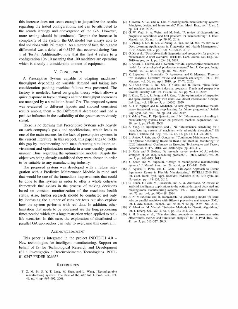
this increase does not seem enough to jeopardize the resultsregarding the tested configurations, and can be attributed tothe search strategy and convergence of the GA. However,more testing should be conducted. Despite the increase incomplexity of the system, the GA model was always able tofind solutions with 1% margin. As a matter of fact, the biggestdifferential was a deficit of 0,542% that occurred during Run1 of Test4a. Additionally, note that the Test 4 refers to aconfiguration 10×10 meaning that 100 machines are operatingwhich is already a considerable amount of equipment.
V. CONCLUSION
A Prescriptive System capable of adapting machines’throughput depending on variable demand and taking intoconsideration pending machine failures was presented. Thefactory is modelled based on graphs theory which allows aquick response in layout changes and the throughput sequencesare managed by a simulation-based GA. The proposed systemwas evaluated to different layouts and showed consistentresults among them – the Differential decreased and had apositive influence in the availability of the system as previouslystated.
There is no denying that Prescriptive Systems rely heavilyon each company’s goals and specifications, which leads toone of the main reasons for the lack of prescriptive systems inthe current literature. In this respect, this paper tries to tacklethis gap by implementing both manufacturing simulation en-vironment and optimization module in a considerably genericmanner. Thus, regarding the optimization module, despite theobjectives being already established they were chosen in orderto be suitable to any manufacturing industry.
The proposed system was developed with a future inte-gration with a Predictive Maintenance Module in mind andthat would be one of the immediate improvements that couldbe done to this system in order to offer a whole cohesiveframework that assists in the process of making decisionsbased on constant monitorization of the machines healthstatus. Also, further research should be conducted not onlyby increasing the number of runs per tests but also explorehow the system performs with real-data. In addition, otherlimitation that needs to be addressed are the long processingtimes needed which are a huge restriction when applied to real-life scenarios. In this case, the exploration of distributed orparallel GA approaches can help to overcame this constraint.
ACKNOWLEDGMENT
This paper is integrated in the project INDTECH 4.0 –New technologies for intelligent manufacturing. Support onbehalf of IS for Technological Research and Development(SI a Investigacao e Desenvolvimento Tecnologico). POCI-01-0247-FEDER-026653.
REFERENCES
[1] Z. M. Bi, S. Y. T. Lang, W. Shen, and L. Wang, “Reconfigurablemanufacturing systems: The state of the art,” Int. J. Prod. Res., vol.46, no. 4, pp. 967–992, 2008.
[2] Y. Koren, X. Gu, and W. Guo, “Reconfigurable manufacturing systems:Principles, design, and future trends,” Front. Mech. Eng., vol. 13, no. 2,pp. 121–136, 2018.
[3] G. W. Vogl, B. A. Weiss, and M. Helu, “A review of diagnostic andprognostic capabilities and best practices for manufacturing,” J. Intell.Manuf., vol. 30, no. 1, pp. 79–95, 2019.
[4] L. Zhang, J. Lin, B. Liu, Z. Zhang, X. Yan, and M. Wei, “A Review onDeep Learning Applications in Prognostics and Health Management,”IEEE Access, vol. 7, pp. 162415–162438, 2019.
[5] G. Xu et al., “Data-driven fault diagnostics and prognostics for predictivemaintenance: A brief overview,” IEEE Int. Conf. Autom. Sci. Eng., vol.2019-Augus, no. 1, pp. 103–108, 2019.
[6] F. Ansari, R. Glawar, and T. Nemeth, “PriMa: a prescriptive maintenancemodel for cyber-physical production systems,” Int. J. Comput. Integr.Manuf., vol. 32, no. 4–5, pp. 482–503, 2019.
[7] K. Lepenioti, A. Bousdekis, D. Apostolou, and G. Mentzas, “Prescrip-tive analytics: Literature review and research challenges,” Int. J. Inf.Manage., vol. 50, no. April 2019, pp. 57–70, 2020.
[8] A. Diez-Olivan, J. Del Ser, D. Galar, and B. Sierra, “Data fusionand machine learning for industrial prognosis: Trends and perspectivestowards Industry 4.0,” Inf. Fusion, vol. 50, pp. 92–111, 2019.
[9] F. Zhao, X. Liu, R. Peng, and J. Kang, “Joint optimization of inspectionand spare ordering policy with multi-level defect information,” Comput.Ind. Eng., vol. 139, no. 3, p. 106205, 2020.
[10] K. T. P. Nguyen and K. Medjaher, “A new dynamic predictive mainte-nance framework using deep learning for failure prognostics,” Reliab.Eng. Syst. Saf., vol. 188, pp. 251–262, 2019.
[11] Z. (Max) Yang, D. Djurdjanovic, and J. Ni, “Maintenance scheduling inmanufacturing systems based on predicted machine degradation,” vol.19, no. 1, pp. 87–98, 2008.
[12] Z. Yang, D. Djurdjanovic, and J. Ni, “Maintenance scheduling for amanufacturing system of machines with adjustable throughput,” IIETrans. (Institute Ind. Eng., vol. 39, no. 12, pp. 1111–1125, 2007.
[13] L. Antao, J. Reis, and G. Goncalves, “Continuous Maintenance Systemfor Optimal Scheduling Based on Real-Time Machine Monitoring,” inIEEE International Conference on Emerging Technologies and FactoryAutomation, ETFA, 2018, vol. 2018-Septe, pp. 410–417.
[14] B. Calis and S. Bulkan, “A research survey: review of AI solutionstrategies of job shop scheduling problem,” J. Intell. Manuf., vol. 26,no. 5, pp. 961–973, 2015.
[15] Y. Koren and M. Shpitalni, “Design of reconfigurable manufacturingsystems,” J. Manuf. Syst., vol. 29, no. 4, pp. 130–141, 2010.
[16] S. Aguiar, R. Pinto, and G. Gonc, “Life-cycle Approach to ExtendEquipment Re-use in Flexible Manufacturing,” INTELLI 2016 FifthInt. Conf. Intell. Syst. Appl. (includes InManEnt 2016) Life-cycle, no.November, pp. 148–153, 2016.
[17] C. Renzi, F. Leali, M. Cavazzuti, and A. O. Andrisano, “A review onartificial intelligence applications to the optimal design of dedicated andreconfigurable manufacturing systems,” Int. J. Adv. Manuf. Technol.,vol. 72, no. 1–4, pp. 403–418, 2014.
[18] S. N. Mirabedini and H. Iranmanesh, “A scheduling model for serialjobs on parallel machines with different preventive maintenance (PM),”Int. J. Adv. Manuf. Technol., vol. 70, no. 9–12, pp. 1579–1589, 2014.
[19] K. Jebari and M. Madiafi, “Selection Methods for Genetic Algorithms,”Int. J. Emerg. Sci., vol. 3, no. 4, pp. 333–344, 2013.
[20] S. H. Huang et al., “Manufacturing productivity improvement usingeffectiveness metrics and simulation analysis,” Int. J. Prod. Res., vol.41, no. 3, pp. 513–527, 2003.
45

A Cross-Platform Communication Mechanismfor ROS-Based Cyber-Physical System
Rui Zhao, Xu Tao, Davide Conzon, Enrico FerreraLINKS Foundation
via Pier Carlo Boggio 61,Turin,Italy
Yenchia YuTongji University
4800 Cao’an Road,Shanghai,
Abstract—Recently, one of the main research topics in thecontext of application of Cyber-Physical System (CPS) in theSmart City and Industry 4.0 scenarios is the one related to theuse of Robot Operating System (ROS)-based CPS. Specifically,one of the main interest is to allow a ROS-based smart robotcommunicating with other heterogeneous Internet of Things (IoT)applications in an intelligent environment to efficiently react tothe system requirements and environment changes. However,the communication between the IoT systems will face manychallenges and increase the cost and risks that lead to therequirement of a cross-platform communication for bridging theROS-based CPS and other heterogeneous IoT applications.
This paper introduces ROS Edge Node for the interoperabilitybetween Robotics domain and other IoT domains, leveragingthe highly modular BRAIN-IoT federation, which allows to de-centralize, compose and dynamically federate the heterogeneousIoT platforms using OSGi specification, thanks to its dynamicmodularity and wide usage in IoT middlewares. Together withthe flexible integration with existing IoT devices/platforms withinBRAIN-IoT platform, the event-driven asynchronous communi-cation mechanism realizes cross-platform interaction with ROS-based CPS and solves the major challenges faced. This commu-nication mechanism allows dynamic deployment of new function-alities for enhancing/extending the behaviour of robots accordingto external events. In addition, some specific behaviours to new”virgin” robots, which might be needed to extend the fleet ofrobots or replace damaged/low batteries ones can be dynamicallydeployed at the setup phase. In BRAIN-IoT platform, EdgeNode behaves as IoT devices/platform adaptors which integratethe existing IoT devices/platforms. The ROS Edge Node is onetype of the Edge Node, which bridges the underlying ROS-based robotics systems and BRAIN-IoT execution environment,thus communicates with various IoT systems connected to theBRAIN-IoT platform. A Service Robotic use case is developed todemonstrate the proposed solution, it shows how the ROS EdgeNode enables the fast adaptivity and interoperability betweenheterogeneous IoT domains in a federated environment.
Index Terms—Brain-IoT, Cyber-Physical System (CPS), Ser-vice Robotics, IoT Middleware, Cross-platform Communication,OSGi
I. INTRODUCTION
Nowadays, CPS are widely used in various aspects in oursociety, including but not limiting in areas such as manufac-turing, energy, health, transportation and intelligent buildings,causing significant socio-economic impacts. CPS are defined
as physical and engineered systems whose operations are mon-itored, coordinated, controlled and integrated by a computingand communication core. To realize such an intelligent system,various technologies need to be involved, including sensor andactuator technology etc. Together with IoT, Cloud computingand Cognitive computing, they become the main technologiesof Industry 4.0 [1]. Specially, CPS and IoT are often discussedtogether, not only because they have many similarities but alsobecause they are the foundations of the intelligent productionenvironment, in another word, the smart factories, which isone of the most important topics of Industry 4.0.
The communication is an important research topic for bothof CPS and IoT. As more and more different devices willbe integrated in an intelligent production environment, therequirement of communication between different CPSs orbetween CPS and IoT devices are becoming more and moresignificant. For example, in a smart factory, different CPSssuch as Autonomous Mobile Robots (AMR) [2] need tocommunicate with each other for cooperation, or an AMRneeds to communicate with IoT devices such as automaticdoors when it needs to cross different zones in the factory.However, such communication is not that easy to realize sinceheterogeneity is a basic property for both CPS and IoT devices.
On the one hand, heterogeneity exists because differentCPS and IoT devices use different technologies in hardware,software, or communication method due to different needs. Onthe other hand, it is because the manufacturers of the devicesare different. Different manufacturers will design the deviceaccording to their own standards. Devices from different man-ufacturers, even if they are using the same technologies, theirprotocol will be different. According to the latest statistics [3],there are officially 620 IoT platform companies in the globalopen market in 2019, in which 50% of the platforms focuson industrial use. From the perspective of communication,devices from these companies could use hundreds of differentcommunication protocols which makes the standardization ofcommunication protocol extremely difficult. In the recent yearsof research, the idea of using middleware to realize cross-platform communication is proposed.
This paper presents a novel adaptor, ROS Edge Node, which
Copyright © 2020 for this paper by its authors. Use permitted under Creative Commons License Attribution 4.0 International (CC BY 4.0).
46

implements an event-driven asynchronous cross-platform com-munication mechanism for ROS-based CPS. The work is apart of the H2020 research project BRAIN-IoT [4] that is afederation enabling the dynamic deployment, orchestration andmonitoring of the distributed IoT applications leveraging theOSGi [5] technology, since OSGi is a series of specificationsfor Java dynamic modular system, it provides the dynamicityfor the life cycle management of software components. Oneof the main functions is to make components as decoupledas possible, and to allow components to dynamically discoverwith each other, so that programmers can develop refinable,reusable, and assistive components in accordance with thesespecifications. Nowadays, OSGi is the widest used technologyto support implementations of IoT abstraction layers. Forexample, Bosch ProSyst and Eurotech are two examplesof companies providing OSGi-based IoT gateways; Oracle®Fusion Middleware [6] is developed for developing JavaEnterprise Edition (EE) management applications for OracleWebLogic Server; SNPS [7] is an OSGi-based middlewarefor Wireless Sensor Networks; The OSGi-based softwareplatform Eclipse SensiNact [8] provides support in technicalaspects (e.g. Connectivity, Interoperability, Data processing,and Developer Tool) related to smart city platforms. BRAIN-IoT platform is implemented with OSGi and it aims integratingwith generic existing IoT devices or IoT platforms or existingIoT middlewares to allow them communicating with eachother. ROS Edge Node is one implementation of the BRAIN-IoT Edge Node mainly focused on the integration of roboticsplatforms in IoT domain allowing to interoperate with otherheterogeneous IoT devices by mapping the ROS servicesto OSGi services, to maximize the connectivity of robotswithin IoT systems. ROS Edge Node is a modular softwarecomponent of the BRAIN-Io platform. It provides four mainfeatures: 1) Interoperability: it provides the connectivity to IoTplatforms connected to BRAIN-IoT solution. 2) Plug & Play:leveraging the OSGi specification, the component followsan event-driven approach and it is developed as a softwaremodule that can be deployed/undeployed at runtime withoutinterrupting other running services. 3) Automatic Adaptation,it provides a code generator to automatically expose the ad-hoc ROS services provided by different ROS-based CPSs andspeeds up the adaptor development process. 4) Standards Com-pliant, it exploits the Web of Things (WoT) Thing Description(TD) [9] describing the services provided by the ROS-basedCPS, making it more portable to the production environment,not restrict to the OSGi implementation.
The rest of this paper is organized as follows. Section IIintroduces the state of the art of the solutions similar to the oneproposed in this paper in multiple domains and the challengesto be addressed typically by these software. It also outlines therelevant technologies used to develop the proposed solution.Section III describes the architecture of the ROS Edge Node,functionalities and development process. Section IV imple-ments a simple robotic application to validate the solution ina distributed environment. Finally, the paper concludes withthe Section V to provide a summary of the cross-platform
communication mechanism for ROS-based CPS and the futurework being undertaken.
II. BACKGROUND
A. State of the Art
One of the most popular example of CPSs is representedby smart industrial robots. This sector is really fragmented,in terms of hardware and software architectures, But in re-cent years, more and more robots have begun adopting onecommon technology, the middleware ROS. According to theannual ROS Metrics Report for 2019 [10], there are near150 types of documented robots available to the communitywith ROS drivers, and in recent years, the total number ofpapers citing “ROS: an opensource Robot Operating System”(Quigley et al.,2009) increase at an annual rate of 20% to 30%.More and more famous robot vendors such as Asea BrownBoveri (ABB) Ltd., Comau Spa. and Kuka AG are starting tosupport ROS in some models of their robots. ROS is the widestused abstraction layer for robotics. However, even the robotsare using ROS middleware, the problems in communicationstill exists. ROS-based CPS are often used to communicatewith other heterogeneous IoT applications to satisfy systemrequirements and react physical environment changes. Thereare two existing middlewares for interacting with ROS-basedCPS.
The ROS–YARP Framework for Middleware Interop-erability [11]: ROS and Yet Another Robot Platform (YARP)[12] are the most popular robotics middlewares. YARP ismore used in the domain of humanoid robots and develop-mental robotics, whereas ROS has higher focus on mobilerobots. They have complementary functions and many roboticplatforms may benefit from using functions from both. Butit’s not an easy task mainly due to fundamental differencesin the communication architecture. This approach generatesthe “bridging gap” code from a configuration file, connectingYARP ports and ROS topics through code-generated YARPbottles. It supports YARP/ROS and viceversa sender/receiverconfigurations. Reading from/sending to ROS topics needs anadditional conversion, which is handled by the existing run-time YARP to ROS converter. The generator abstracts YARPand ROS developers from dealing directly with interoperabilityissues. However, this work is only focusing the interoperabilityamong robotics middlewares.
ROBIN Middleware for CPS [13]: ROBIN is a mid-dleware funded by European H2020 program providing aneffective, bidirectional, reliable and structured data interchangemechanism to address the demand for flexible robotics incontemporary industrial environments and the necessity tointegrate robots and automation equipment in an efficientmanner. ROBIN, the robotics bridge to industrial automation,aims to allow the interoperability between robotics and au-tomation systems by enabling the communication betweenROS and CODESYS [14], which is a softPLC1, a real-timemulti-task control kernel, that can run on embedded devices
1http://www.softplc.com/
47

and that supports a variety of fieldbuses, and other industrialnetwork protocols. CODESYS handles the establishment ofexternal communication with the equipment via a fieldbusand communicates with ROS through the developed roboticsbridge. More specifically, since ROS implementation followsthe publisher–subscriber messaging pattern, which enablesexchanging data between ROS nodes [15], A ROS node isbasically a process that performs computation and it is an exe-cutable program running inside the robotics application. Manynodes can be implemented in ROS packages. The proposedbridging mechanism allows developers to create or includein existing ROS packages the valuable feature of connectingwith an external device via fieldbuses or industrial networkprotocols promoted by the softPLC bridge. Multiple ROSnodes can access and modify the data shared with the softPLCapplication in ROS. The information to be propagated to theexternal devices could be published on a ROS topic, handledby the developed bridge, and then relayed by CODESYS tothe proper industrial network protocol or fieldbus.
B. Problems with State of the Art
ROS allows the communication between heterogeneousdevices, being deployable on heterogeneous platforms. AfterROS is deployed on the device, it can use ROS as communi-cation method to communicate. However, it can only supportcommunication between devices developed based on ROS,it cannot be used to communicate with off-the-shell devicesusing different technologies. Furthermore, the messages usedin ROS are the original data sent by the device, which hasnot been standardized. The receiver must know the contentof the communication in advance, otherwise it will not beable to understand the received data. In State Of The Art(SOTA), one of the limitations of ROS–YARP middleware isthe applicability area, which is limited to ROS and YARPonly, while CPSs are widely used in various aspects. Therobotic bridge provided by ROBIN project allows the com-munication between ROS and the automation applicationthrough the inter-node communication mechanism in ROS,but it requires the developers to directly create or include inexisting ROS packages the valuable features for interactingwith other external devices via fieldbuses or industrial networkprotocols. This requires to the developers to be expert inROS programming. Besides, the direct operation on existingROS packages may bring the risk of the damaging the basicfunctionalities. Moreover, in the real production environment,the robotics applications are significantly sophisticated anddynamic, requiring to the bridge to be flexible enough to reactto the continuously changing production environment; to allowthis the robotic bridge needs to support the update at runtimeand the deployment on demand and this feature is not feasibleusing only native ROS.
Instead, ROS Edge Node bridges ROS and other IoTplatforms using OSGi specification, in such way, the robot’sbehaviours can be developed at the application level usingOSGi instead of ROS. And this allows to have all the advancedOSGi capabilities applied in robotics scenario(i.e., start and
stop atomic behaviours at runtime, deploy new ones, import,update and upgrade behaviours at runtime every time a newmore stable or more secure version is available).
C. Challenges
ROS Edge Node intends to address the gaps mentioned inthe previous section in the current State of The Art (SoTA)and the typical challenges faced in researches on middlewarefor CPS [16], [17]. More specifically, apart from supportingthe interoperability between the ROS-based CPS and otherheterogeneous IoT applications, it also supports adaptivity,security and privacy protection and autonomous operation, asexplained in the following subsections.
Abstraction and Automatic Adaptation: [18] An idealmiddleware for an intelligent environment such as the IoTshould provide abstractions at various levels such as hetero-geneous input and output hardware devices, hardware andsoftware interfaces, data streams, physicality and the de-velopment process. And an Adaptive middleware is usuallymotivated by the need of adapting the middleware to changesin application’s requirements, changes of environmental con-ditions, fixing middleware’s bugs or extending/improving themiddleware functionality. ROS Edge Node solution proposesan approach to create a software component to abstract theROS-based CPS for communicating with other OSGi-basedIoT middlewares/applications through the distributed BRAIN-IoT EventBus. The adaptor can be generated according todifferent ROS platform implementations. For the simplicity,a code generator is provided to speed up the developmentprocess.
Security and Privacy: Automatic communication of real-life objects represents a huge challenge in terms of trust,security and privacy. The security and privacy component isneeded to provide the integrity of the collected data (stream)and to ensure that the user’s privacy is not violated. Thedata can only be able to connect to authenticated/certifiedIoT devices. The management support of security and privacyhas to be considered as a main function of the middle-ware for the IoT. The ROS Edge Node adaptor will beintegrated with the BRAIN-IoT platform, which introducesa holistic end-to-end trust framework and privacy-awarenessand control approach to address the challenge [4]. Currently,the integration between ROS Edge Node and the end-to-endframework guarantees only authenticated ROS-based CPSs canintegrate with BRAIN-IoT platform and communicate withother authenticated IoT systems.
Autonomous Operation: Many CPS applications are con-sidered complex systems which can be in a huge number ofdifferent states at any point of time. It is generally extremelydifficult to develop code to handle all these states effectivelyand in a timely manner. Having middleware that supportsautonomous operations such as self-adaptive, self-resilient, andself-protected services can relax implementing and operatingthese complex CPS applications. The ROS Edge Node ad-dresses this challenge supporting the development of complexIoT solutions for monitoring and controlling physical environ-
48

ments and systems. Specifically, it simplifies the operation ofapplication providing a an event-driven notification method,which allow avoiding to use polling methods to query therobot or mission status, reducing greatly the network traffics.
D. Relevant Technologies
RosJava Open Source Library2: RosJava project providesa pure Java implementation of ROS, and it also can inter-connect to an existing ROS environment through the InternetProtocol (IP) address. It provides a client library for ROScommunications in java that allows Java programmers toquickly interface with ROS topics, services and parametersthrough the eXtensible Markup Language (XML)-RemoteProcedure Call (RPC) [19] protocol. It provides some commonJava API allowing to create new ROS nodes, services, topics innative ROS environment, and the corresponding ROS clients.The library can be fully integrated in OSGi software.
JCodeModel Open Source Library3: JCodeModel is aJava code generation library. It provides common API togenerate Java programs using Java language.
World Wide Web Consortium (W3C) and WoT: In recentyears, W3C organization has developed the WoT [9] standardaiming to achieve interoperability problem between IoT plat-forms and application domains. WoT provides a mechanismfor describing IoT interfaces, allowing IoT devices (physicalor virtual entity) and services to communicate with each other,independent of their underlying implementation, and can spanmultiple network protocols. In addition, WoT also providesa standardized way to define and plan IoT behaviors. WoTArchitecture specification is centered on the scope of W3CWoT standardization, divided into several building blocks.The four core building blocks provided by W3C WoT are:Thing Description, Binding Template, Scripting ApplicationProgramming Interface (API), Security and Privacy Guide-lines. More specifically, The central building block is theWoT TD4, which can describe the metadata of the objectand the network-oriented interfaces and it’s the entry pointof a Thing. TDs are encoded in a JavaScript Object Notation(JSON) format that also allows JSON-based Serialization forLinked Data (JSON-LD) processing, primarily intended tobe a way to use Linked Data in Web-based programmingenvironments. The building blocks allow an application client(a Consumer) to interact with Things that expose diverseprotocols through the three types of Interaction Affordancesdefined by W3C WoT Interaction Model representing the capa-bilities of individual Things: i) Properties (PropertyAffordanceclass) can be used for sensing and controlling parameters,such as getting the current value or setting an operationstate; ii) Actions (ActionAffordance class) model invocation ofphysical (and hence time-consuming) processes, but can alsobe used to abstract RPC-like calls of existing platforms. iii)Events (EventAffordance class) are used for the push model ofcommunication where notifications, discrete events, or streams
2https://github.com/rosjava3https://github.com/phax/jcodemodel4https://w3c.github.io/wot-thing-description/
of values are sent asynchronously to the receiver. TD can beused for flexible implementation and simulation (if required).WoT will break the barrier of interoperability of various IoTplatforms, thereby contributing to the explosive growth of themarket. It doesn’t aim to define a new platform, but to use themetadata to bridge existing platforms and standards.
In this paper, these technologies will be used in the follow-ing aspects. The ROS Edge Node, will be developed as OSGibundles, which can be remotely installed, started, stopped,updated, and uninstalled without requiring a reboot in BRAIN-IoT federation.
RosJava can be considered as the bridge between ROS worldand Java world. It provides an efficient way for the ROS EdgeNode to establish a communication with ROS-based devices.Different ROS functionalities will be mapped into differentOSGi services in the ROS Edge Node. The mapping procedurewill be done automatically through JCodeModel library witha TD of the underlying ROS environment. Anyway, thecorresponding formatting procedure of events and integrationwith BRAIN-IoT framework should be done by developers.
III. ARCHITECTURE
This section details the ROS Edge Node architecture alongwith its role in the overall BRAIN-IoT platform.
A. Overview in BRAIN-IoT Context
ROS Edge Node will be integrated with BRAIN-IoT Fabric[20] infrastructure service, which is composed with a setof the computing resources (physical/virtual machines) andprovides a distributed OSGi execution environment allowingthe interaction between the OSGi services deployed on itthrough events, thanks to the implementation of OSGi Alliancespecifications for Remote Services and Remote Service Admin[5]. Each BRAIN-IoT Fibre is an OSGi R7 framework, anddifferent Brain-IoT OSGi bundles deployed on local andremote Fibres can communicate with each other using somespecific strongly typed BRAIN-IoT events delivered in theasynchronous BRAIN-IoT EventBus [20] according to theBRAIN-IoT approach. The BRAIN-IoT Nodes are the ServiceFabric Fibres with different BRAIN-IoT Services deployedon them, they can be of two types: BRAIN-IoT ProcessingNodes and BRAIN-IoT Edge Nodes. The first ones are asort of Service Fabric Fibres deploying IoT application logicand controlling the CPS behaviours through their adaptorssupported by the machine learning algorithms. The latter onesare Fabric Fibres with the installed edge components deployedon the top of them. BRAIN-IoT Fabric allows users to labelthe BRAIN-IoT nodes, thus to guide where the BRAIN-IoTservice, satifying the required capabilities, should be deployedat runtime. The BRAIN-IoT architecture allows the dynamicredeployment of 1) new functionalities for enhancing/extend-ing the behaviour of robots according to external events. 2)specific behaviours to new ”virgin” robots, which might beneeded to extend the fleet of robots or replace demaged/lowbatteries ones. Each ROS Edge node can be considered asan access point or an adaptor to ROS-based CPS, to allow
49

Fig. 1. ROS Edge Node structure
heterogeneous IoT applications running on the processingnodes to control the robots. In the BRAIN-IoT platform, theauthors’ contribution is to develop the ROS Edge Node asOSGi Declarative Service, so that from the northbound it canreceive the interested BRAIN-IoT events from other differentIoT platforms in a distributed environment, then construct thedata and send to the connected ROS environment. Therefore,any new functionalities for enhancing/extending the behaviourof robots according to external events can be developed usingOSGi instead of ROS. From the southbound, the ROS EdgeNode is able to retrieve the information from ROS and injectto the BRAIN-IoT Fabric as BRAIN-IoT events, which will bereceived by other BRAIN-IoT services. The ROS Edge Nodeaims to achieve the interoperability between heterogeneousIoT applications integrated within BRAIN-IoT platform andthe ROS-based CPSs. It exposes the ROS functionalities asOSGi services.
The architecture of ROS Edge Node is shown in Fig.1. Forits development and validation, the authors have used the ROSsimulation for BRAIN-IoT service robotic use case providedby the Robotnik Automation S.L.L. (see Section IV). TheROS Edge Node has two main requirements: i) to exposeall the relevant ROS functionalities as OSGi services (taskdone by OSGi Service Component). The objective is to makethe adaptor able to interoperate with the ROS environmentleveraging APIs provided by the open source Rosjava project,in this way, the adaptor is able to send/receive the ROSrequest/response messages from/to the ROS services and pub-lish/subscribe to the ROS topics between the OSGi world andROS world. ii) To collect and format of the BRAIN-IoT eventsfrom different sources based on the Publish-Subscribe pattern5
(task done by BRAIN-IoT Robot Service). The adaptor receivesthe events from heterogeneous platforms in the distributedBRAIN-IoT Fabric environment and constructs them as Java
5https://en.wikipedia.org/wiki/Publish\%E2\%80\%93subscribe pattern
objects representing ROS messages, then transforms to ROSenvironment through the exposed OSGi services. In contrast,the adaptor also retrieves the ROS messages from the nativeservices/topics and convert to the BRAIN-IoT events, then de-liver them in the distributed EventBus. The connectivity withROS is configurable through the ROS environment variableROS MASTER URI by default whose value is configurableon-the-fly in order to set up which machine as a ROS masterwhen a new ”virgin” robot join the fleet of robots.
B. ROS Edge Node Approach
The ROS Edge Node adaptor is further explained in thissubsection, detailing its approach, implementation steps andthe addressed challenges.
1) Abstraction of ROS environment: It aims to address theinteroperability challenge when integrating other IoT devicesin BRAIN-IoT platofrm. As Fig.1 shows, the basic function ofROS Edge Node is to map the ROS messages to BRAIN-IoTevents and vice-versa. The BRAIN-IoT services interact witheach other by leveraging the Requirements and Capabilitiesmetadata provided by default by all OSGi Bundles, the eventsissued by a source BRAIN-IoT service contains the sufficientinformation presenting the Requirements of this service, in themeanwhile, the events also identify the Capabilities of the sinkBRAIN-IoT services that will consume them.
The ROS Edge Node simply interconnects to the ROSenvironment thanks to the RosJava library which provides asimple interface enabling the ROS Edge Node to automaticallygenerate a set of Java object classes, which is totally compliantwith native ROS messages’ structure in the ROS environment.The instances of the classes could be transformed to the ROSenvironment. However, it’s not possible to make the BRAIN-IoT events types the same as the names of the native ROSmessages. For a single robot, there could be hundreds of typesof native ROS messages in the ROS environment and theirdata structures are in general very complex, direct mappingbetween the ROS messages types and BRAIN-IoT events isinefficient and will increase the complexity of the usage of theevents for other IoT applications. Also, different robots havingsame functions may use completely different types of ROSmessages as commands. In such case, if directly mapping eachROS message into an event, the difficulty to integrate differentrobots in a system will be increased. Thus, some common datatypes including necessary information need to be defined andshared between diverse IoT applications. So it’s necessary forROS Edge Node to format the received events into the specificJava objects that are compliant with ROS messages.
The ROS Edge Node wraps also the native ROS functionali-ties, exposing them to the OSGi services for heterogeneous IoTapplications’ access, by creating the corresponding ROS ser-vices and publish/subscribe clients in OSGi bundles, throughthe APIs provided by RosJava project. The exposed OSGiservices are a set of java classes containing multiple robotoperations mapped to Java methods. The BRAIN-IoT RobotService in Fig.1 is a wrapper of the exposed OSGi services,with the specific Capabilities information represented by the
50

consumed event types. The ROS Edge Node is responsiblefor communicating with other BRAIN-IoT services usingEvents. When the robot service receives an event from theEventBus, it will construct a ROS message in Java type andperform the corresponding action by calling the exposed ROSfunctionalities. Thanks to the BRAIN-IoT solution, the servicewill be deployed on the BRAIN-IoT Fabric by the event-drivenmechanism. It’s completely de-coupled from the underlyingBRAIN-IoT Fabric runtime.
2) The Autonomous Operation: As mentioned in Sec-tion II-C, supporting autonomous operation is one of thechallenges for a CPS adaptor. In the ROS Edge Node, theautonomous operation is fully supported by a feedback mech-anism: the ROS Edge Node is responsible for continuouslyquerying the execution status of CPS where it is installedand then to issue an response event if the status changes.This allows building services, which leverage the ROS EdgeNode, which are “smarter” and reducing the communicationworkload on the EventBus,(see Fig.6 in Section IV).
3) Automatic Adaptation and Standards Compliant: Thisis a usual task that needs to be supported by such type ofsolutions. For ROS-based devices, this challenge is addressedby ROS Edge Node. As mentioned above, the exposed servicecomponents are a set of java classes containing multiplemethods for robot operations. The operations are done throughROS services/topics clients in Java code via simple APIprovided by RosJava library. Normally, when developers createthe java clients for the used native ROS functionalities, the javaclients could be grouped in one or more Java classes for betterorganization.
Since the services or topics and their related methods in acomponent class have the same structures, the authors achieveto automatically realize the adaption by creating a CodeGenerator to automatically generate the OSGi service classesfrom a predefined configuration file as the input. Since allentities in ROS-based CPS communicate through services andtopics, the authors choose to use the W3C WoT TD, whichis a general standard for both integrating diverse devices andinteroperability of diverse applications to describe the ROSfunctionalities. In the proposed solution, WoT TD describesthe interfaces for OSGi to expose the ROS services and topics.In this way, a standard approach is used to describe the ROSAPI and to generate the corresponding OSGi services, thisallows to have a solution WoT integration-ready and highlyreusable. The ROS functionalities are compliant with TDspecification: 1) the topics are as Properties Interaction Af-fordances 2) the services are described as Actions InteractionAffordances.
For a ROS service, the part of TD file is shown as Fig.2.More specially, there could be a set of ROS services describedin the Actions element, and for each of them, the informa-tion will include serviceClientName, serviceName, service-Type, serviceRequestType, serviceResponseType and Class-Name, which are used by the Code Generator to createservice clients in OSGi world. The Code Generator uses theClassName property to generate multiple component classes
Fig. 2. Thing Description of ROS Environment
Fig. 3. Expose of ROS Environment to OSGI Services Using WoT TD
for different types of robot functionalities, and each componentcan contain multiple service clients and the different operationscould be done through the methods called by each client. Thevalues of other properties will be used as the arguments of thegenerated methods. Similarly, the ROS topics will be describedin the Properties element, including the information aboutRole, ReferenceName, TopicName, TopicType, MessageTypeand ClassName. The value of the Role property could bepublisher or subscriber, so the corresponding client typewill be created with the client name equal to the value ofReferenceName.
To automatically expose relevant ROS functionalities andspeed up the ROS Edge Node development for the ad-hocROS platforms, A code generator is provided to generate theartefacts automatically by taking the TD as a configurationfile, to describe the ROS services and topics, as shown inFig.3, which is demonstrated in Fig.5 in Section IV. Thisapproach greatly reduces the dependence for developers in theprocess of adapting to different ROS-based CPSs, increasingthe development simplicity. Developers can therefore focusmore on the development of BRAIN-IoT services rather thanon adaptation work.
51

Fig. 4. Warehouse simulation
IV. USE CASE DEMONSTRATION
In this section, a brief description of ROS simulationused for the Brain-IoT Service Robotic Use Case and theresult obtained evaluating the cross-platform communicationmechanism using it are presented.
A. Use Case Introduction
Smart warehouse is a popular application of Industry 4.0.The basic elements of a smart warehouse include AMR,heterogeneous IoT devices and cargo carts. To be “smart”,these elements need to interact and cooperate with each other.The use case aims to realize one of the basic function of smartwarehouse: the cart movement. The Fig.4 shows the warehousewith three zones in 3D perspective in Gazebo simulator: adocking area, a unloading area and a storage area. The lasttwo zones are separated by an automatic door, which is anIoT device. There are three rb1 base robots (robot1, robot2 androbot3) in the docking area responsible for moving all carts tothe storage area. In the unloading area there are 3 carts (cart1,cart2 and cart3) and each has a different QR code attached.The storage area is divided into three sub-zones (zone A, zoneB and zone C). The robots need to pick up these carts fromthe unloading area, pass through the door and place them inthe storage area according to the received commands from therobot application.
B. Robot System Design
In order to demonstrate how the adaptor bridges the ROSenvironment and the OSGi environment, the authors imple-mented a simple multi-agent robot system based on OSGi tocontrol the simulated robots.
The system contains three system parts: a Robot BehaviourService, a ROS Edge Node Service and a Door Edge NodeService. There are several tables storing the coordinates ofthe carts and the storage positions will be used as the sharedresources among three robots. In the ROS simulation, the basictask for each robot is that starting from the docking area, itneeds to go to the picking area for picking up a cart, then passthrough a door to the storage area and finally place the cart,the procedure is controlled by the Robot Behaviour Service.
Fig. 5. Method Blocks of Automatically Exposed ROS Services from TD file
The new functionalities for enhancing/extending the behaviourof robots according to external events can be dynamicallyupgraded and redeployed in the BRAIN-IT architecture. Basedon that, the authors define the events in three types: action,query and cancellation. The events in action type includesWriteGoTo, PickCart and PlaceCart, which present the basicfunctions of the robot. There are also other events defined forquerying the execution status of corresponding actions and forcancelling current actions.
In the use case, there are three services related to theWriteGoTo action event, a WoT TD file is defined for the com-munication with the robotic system, the code generator usingthe TD as input will automatically generate the class namedGoToComponent as shown in Fig.5 by using the open sourceJCodeModel library which is a Java code generation library.Specifically, according to the ROS functionalities describedin the TD, there are three ROS service clients (e.g. gotoRun,gotoCancel, gotoQuery) will be created in the generated class.when the ROS Edge Node receives an event, the correspondingconstruct XXX Msg method representing the operation of theclient will be called to construct a Java object representing theROS message as a ROS service request to be sent to the nativeROS environment through the call XXX method of the serviceclient, where the XXX stands for the name of the service client.
The Robot Behaviour Service continuously checks theshared tables to get a task and then it controls the robotsthrough a sequence of BRAIN-IoT events to finish the mission.The events will be received by the ROS Edge Node Serviceand sent to the connected robot. As an example shown in Fig.6,after the ROS Edge Node receives a WriteGoTo event from theController Service containing the coordinates where the robotshould go, with the autonomous operation of the ROS EdgeNode, only twice communications are needed between theController Service and the ROS Edge Node, one for sendingthe action command, while the other one for receiving theaction result. When the robots detected a door on the wayto the storage area, it reports the situation and the RobotBehaviour Service will instruct the Door Edge Node Serviceto open the door.
52

Fig. 6. Communication Procedure of “WriteGoTo” action for ROS Edge Node
Fig. 7. Deployment of Robot System in the distributed BRAIN-IoT Fabric
In the test, the robot system above is deployed on a dis-tributed Fabric environment containing multiple Raspberry Pisand one Linux server running the ROS simulation as BRAIN-IoT nodes in a same network. The Linux server is labeledin advance when BRAIN-IoT Fabric cluster is created and theROS Edge Node Service is automatically deployed on it whenthe label is detected. Since there are three simulated robots,three instances of the ROS Edge Node Service instantiatedby OSGi Configuration Admin Service Specification [5] toconnect to the robots through IP address, the interested eventswill be delivered to the ROS Edge Node through the integratedEventBus. In the multi-agent system, each Robot BehaviourService instance will control one robot to take a task fromthe shared table, after one task is finished, it will start nextiteration. In this case, the deployment of Robot BehaviourService and the ROS Edge Node Service in the real physicalenvironment can be shown as Fig.7. Meanwhile, The doorin the simulation environment is a IoT device controlled bythe Door Edge Node Service, which is simulated in the ROSenvironment.
C. Validation in Simulation Environment
When the multi-agent robot system is activated, each RobotBehavior Service instance will check the shared cart table to
find the pending tasks. When a cart to be moved is found inthe table, Robot Behavior will change the status of the cartto moving and start the moving procedure. Robot behaviorswill deliver a sequence of events to the corresponding ROSEdge Node one by one to command the robot to move to cartposition, pick up the cart, move the cart to specific positionin the storage area and finally drop the cart. When ROS EdgeNode receives an event, it extracts the information containedin the event, constructs a ROS message in Java type, and com-municates with the robot through the exposed OSGi services.ROS Edge Node is responsible for continuously querying theexecution status from the specific ROS service/topic, when theaction of an event is finished or something wrong happened,a feedback event will be issued to inform the Robot Behaviorto ask for the next action. During the moving procedure, ifthe door is closed, it will scan the QR code of the automateddoor, and return a DoorFound event to the Robot Behavior.The Robot Behaviour will send a OpenDoor event to the DoorEdge Node service to open the door.
After finishing the moving procedure, the Robot BehaviorService will change the status of the cart to moved in the tableand search for the next mission. Finally all carts are moved inROS simulation.
D. Validation in Physical Environment
To prove the feasibility of the approach proposed in thepaper, ROS Edge node has been installed on a real rb-1 basemobile robot. Due to the difference of the simulated worldand the physical world, the autonomous robotic system is notused in the physical environment, but authors implementedan Orchestrator service, which provides a simple interfacefor users to manually send a sequence of BRAIN-IoT eventsincluding the coordinates to control the actions of the robots ina physical environment. The Orchestrator is implemented as aOSGi Declarative Service and it injects a sort of commands inthe Apache Felix Gogo 6, which is a subproject of Apache Fe-lix implementing a command line shell for OSGi, which couldbe accessed via its web interface in a distributed BRAIN-IoTFabric environment. When a user enters the command in Gogoshell, the corresponding method in the Orchestrator will issuea specific event to EventBus. The Orchestrator service couldbe installed on any BRAIN-IoT node. Finally, ROS Edge Nodeis able to receive the events and the robot will move towardsto the target positions.
V. CONCLUSION AND FUTURE WORK
The paper has presented the ROS Edge Node, which enablesthe interoperability between the ROS-based CPS applicationsand other heterogeneous IoT platforms in a sophisticated IoTsoftware ecosystem, based on the available services in BRAIN-IoT framework. This solution provides several innovativefeatures, to ease such interaction. Firstly, it can be dynamicallydeployed and flexibly scaled on demand to connect to multipleROS-based CPSs at runtime whenever a new CPS joins the
6https://felix.apache.org/documentation/subprojects/apache-felix-gogo.html
53

cluster. Secondly, it provides an approach to automaticallyexpose the ROS functionalities as OSGi services for bridgingthe ROS world and OSGi world. Thirdly, ROS Edge Nodemaximizes the flexibility of the mechanism by supportingcustomized autonomous operation to detect the changes ofaction status and issue feedback events, thus greatly reducesthe communication load on EventBus and its dependenceon other system components. Finally, the use of WoT TDstandardizes the description of the ROS functionalities.
Compared with the existing CPS middleware or IoT middle-ware, the proposed solution presents several advantages, butsome further developments are still ongoing. The integrationwith the BRAIN-IoT End-to-End Security Framework arestill under development. Besides, its functionalities will beenriched more, such as the graphical monitoring of robot statusand the warehouse coordinates at runtime by integrating withother BRAIN-IoT monitoring tools. ROS Edge Node will betested on the real robots with a more complex Robotics usecase and the performance will be compared with other existingsolutions, in the future work.
ACKNOWLEDGMENT
The work presented here was part of the project ”Brain-IoT-model-Based fRamework for dependable sensing and Actua-tion in iNtelligent decentralized IoT systems” and receivedfunding from the European Union’s Horizon 2020 researchand innovation programme under grant agreement No 780089.
The simulation environment is provided by Robotnik Au-tomation S.L.L.
REFERENCES
[1] N. Boulila, “Cyber-physical systems and industry 4.0: Properties, struc-ture, communication, and behavior,” 04 2019.
[2] S. Barai, M. K. Kundu, and B. Sau, “Path following of autonomousmobile robot with distance measurement using rfid tags,” in 2019 IEEEInternational Symposium on Measurement and Control in Robotics(ISMCR), 2019, pp. A3–4–1–A3–4–4.
[3] nud Lasse Lueth, “Iot platform companies landscape2019/2020: 620 iot platforms globally,” https://iot-analytics.com/iot-platform-companies-landscape-2020/, December 2019.
[4] D. Conzon, M. R. A. Rashid, X. Tao, A. Soriano, R. Nicholson, andE. Ferrera, “Brain-iot: Model-based framework for dependable sensingand actuation in intelligent decentralized iot systems,” in 2019 4thInternational Conference on Computing, Communications and Security(ICCCS), 2019, pp. 1–8.
[5] O. Alliance, “Osgi core release 7,” OSGi Alliance, Tech. Rep., Apr.2018.
[6] https://docs.oracle.com/middleware/1212/wls/WLPRG/overview.htm#WLPRG107.
[7] G. Di Modica, F. Pantano, and O. Tomarchio, “Snps: An osgi-basedmiddleware for wireless sensor networks,” 09 2013, pp. 1–12.
[8] https://projects.eclipse.org/proposals/eclipse-sensinact.[9] https://www.w3.org/TR/wot-architecture/.
[10] “Community metrics report,” http://download.ros.org/downloads/metrics/metrics-report-2019-07.pdf, July 2019.
[11] M. Aragao, P. Moreno, and A. Bernardino, “Middleware interoperabilityfor robotics: A ros–yarp framework,” Frontiers Robotics AI, vol. 3, p. 64,2016.
[12] G. Metta, P. Fitzpatrick, and L. Natale, “Yarp: Yet another robotplatform,” International Journal of Advanced Robotic Systems, vol. 3,03 2006.
[13] R. Arrais, P. Ribeiro, H. Domingos, and G. Veiga, “Robin:An open-source middleware for plug‘n’produce of cyber-physicalsystems,” International Journal of Advanced Robotic Systems, vol. 17,no. 3, p. 1729881420910316, 2020. [Online]. Available: https://doi.org/10.1177/1729881420910316
[14] A. Pletsch, “Codesys eases programming for multiple controls hard-ware,” vol. 50, pp. 34–35, 06 2004.
[15] A. Santos, A. Cunha, N. Macedo, R. Arrais, and F. N. dos Santos,“Mining the usage patterns of ros primitives,” in 2017 IEEE/RSJInternational Conference on Intelligent Robots and Systems (IROS),2017, pp. 3855–3860.
[16] N. Mohamed, J. Al-Jaroodi, S. Lazarova-Molnar, and I. Jawhar, “Mid-dleware challenges for cyber-physical systems,” Scalable Computing.Practice and Experience, vol. 18, no. 4, pp. 331–346, 2017.
[17] M. A. Chaqfeh and N. Mohamed, “Challenges in middleware solutionsfor the internet of things,” pp. 21–26, 2012.
[18] N. Rosa, D. Cavalcanti, G. Campos, and A. Silva, “Adaptive middlewarein go - a software architecture-based approach,” J Internet Serv Appl 11,3 (2020), 05 2020.
[19] T. Tomlinson and J. VanDyk, “Xml-rpc,” 01 2010.[20] R.Nicholson, T.Ward, D.Baum, X.Tao, D.Conzon, and E.Ferrera, “Dy-
namic fog computing platform for event-driven deployment and orches-tration of distributed internet of things applications,” pp. 239–246, 2019.
54

REPLICA: A Solution for Next Generation IoT andDigital Twin Based Fault Diagnosis and Predictive
MaintenanceRosaria Rossini, Davide Conzon, Gianluca Prato,
Claudio PastroneIoT and Pervasive Technology Area
LINKS FoundationTurin, Italy
{name.surname}@linksfoundation.com
Joao Reis, Gil GoncalvesSYSTEC, Research Center for Systems and Technologies
Faculty of Engineering, University of PortoPorto, Portugal
{jpcreis , gil}@fe.up.pt
Abstract—Nowadays competitiveness goes through several as-pects: digitalization, productivity and environmental impact.Technology is advancing fast and helping industries to obtainmore and more detailed data about their processes and equip-ment. In fact, the possibility to monitor and control each partof the process is a strong base on which a more intelligentand focused control can be built. Technology advance bringsinnovation and the possibility to manage the production interms of ”near future” through AI prediction and decision-making support. Forecasting demands and planning production,optimizing process by reducing costs and improving efficiencywithout corrupting the quality of the product is a big challengeat the plant level. In this paper, a flexible, scalable architecturefor intelligent digital twin realization called REPLICA has beenproposed to cope with such problem and help industries toadvance and discover possible optimizations. This architecturesits on top of two European projects, namely CPSwarm andRECLAIM, where their contribution focus on distributed sim-ulation and optimization, and Adaptive Sensorial Networks,correspondingly. As a validation process, a hypothetical use caseis presented, detailing the key differentiating points and benefitsof the proposed architecture.
Index Terms—IoT, Digital Twin, AI, Fault Diagnosis, PredictiveMaintenance
I. INTRODUCTION
In the era of Industrial Internet of Things (IIoT) and Industry4.0, complex electromechanical systems can be equipped witha variety of sensors providing new opportunities for thedevelopment of Health Monitoring and Management Systems.These new opportunities target an optimum exploitation ofavailable information in order to maximize the performanceof the machinery and optimize the process. Focusing on theincrease of production reliability and safety, as well as on thereduction of costs, there is an ever increasing industrial neednot only for accurate and on time online diagnostics, but alsofor a robust and early estimation of the Remaining Useful Life(RUL) of the defected components, within a high confidenceinterval, independent of the operating conditions.
For this reason, and many others, a new concept of ’inter-action’ with the process arose; a concept of controlling and
monitoring a replica instead of the real object, a perfect virtualreplica that interacts with both humans and machines: a DigitalTwin. The concept of “twin” is originally derived from Na-tional Aeronautics and Space Administration (NASA)’s ApolloProject when the aircraft’s twin body was a real physicalsystem [1]. Twin models help astronauts and staffs makedecisions under emergency situations. Digital twin integratesthe life cycle of a machine [2], and achieves a closed loopand optimisation of the machine design, production, operation,and maintenance, etc. In Magargle et al. [3], a multi-physicaltwin model is built to monitor the status of the brake systemthrough multiple angles. NASA hopes to realise the healthmanagement and residual life prediction of the aircraft bybuilding a multi-physical, multi-scale Digital Twin model [4],furthermore serveral roles are envisioned for Digital Twin inthe industry 4.0 scenario [5].
The present paper focuses on the proposition of an intel-ligent digital twin architecture called REclaim oPtimizationand simuLatIon Cooperation in digitAl twin (REPLICA), thatfocuses on two important aspects: 1) plug’n’play of modelson demand and 2) Workflow design to orchestrate the modelsused in the Digital Twin itself. Aspect (1) aims to easethe integration and removal of models into digital twins,whenever a new version of the software is available or itperforms any necessary correction in the used models. Thegoal of the latter aspect is dedicated to the creation of apipeline that can manage the flow of data among all theavailable models. These models might be from pure dataprocessing and decision making, from sensor and actuatorintegration, to third party synchronization with informationsystems such as Manufacturing Execution Systems (MES)or Enterprise Resource Planning (ERP). Most digital twins,and in particular intelligent digital twin architectures focuson providing the best set of models that one should haveto accomplish, e.g. predictive maintenance, from the type ofsimulation required to machine learning models that should berefined based on newly acquired data. Furthermore, REPLICAcan allow a flexible and distributed deployment in such a
Copyright © 2020 for this paper by its authors. Use permitted under Creative Commons License Attribution 4.0 International (CC BY 4.0).
55

way that both completely cloud or mixed edge/cloud solutionsdeployment are accepted, with respect to the need of thespecific application.
However, these architectures are normally rigid and do notsupport changing software models or even easily set up theorchestration of those resources. Fixed data flows are generallyhardcoded, meaning that if an implementation needs to bemodified, changes in code are required. This is often notrecommended since these changes might negatively influencethe stability of the system. To this intent, an architecture thataddresses these challenges is presented.
The paper is organized as follows: in Section II, the authorsintroduce a literature review about predictive maintenance andfault diagnosis based on digital twin. Complementary, SectionIII presents the core technologies of the solution presentedin this paper. Section IV describes the architecture of thesolution proposed and Section V presents a first prototypeimplementation followed by Section VI in which a possibleapplication is described. Finally, Section VII concludes thepaper by summarizing and discussing the work.
II. LITERATURE REVIEW
With the rapid advancement of Cyber-Physical ProductionSystems, Artificial Intelligence (AI) and IIoT, Digital Twin(DT) has gained increasing attention due to its capability toadapt and replicate the industry processes. Accordingly tothese changes, many different DT architectures have been pro-posed to realize several use cases in an intelligent and complexproduction system. Industrial AI [6] brings to the processesself-aware, self-adapt, and self-configure functionalities andfacilitates the integration of the DT.
In [7], the authors propose to insert an intelligent DT inthe Cyber Layer architecture. The concept has been partiallyrealized with two industrial use cases, namely a modular pro-duction system as well as a metal forming industrial processto show its potential and gains over the challenges in Cyber-Physical System (CPS), i.e., synchronization throughout thelifecycle of a cyber-physical production system; developmentof the DT, which can contain different models; the interac-tion between DT, both for the purpose of co-simulation andoperation data exchange; and the active data acquisition.
In [8], the authors present a methodology for enablingDT using advanced physics-based modelling in predictivemaintenance. This methodology for advanced physics-basedmodeling aims to enable the DT concept in predictive main-tenance application and consists of two main points: digitalmodel creation and DT enabling. Then, the user is able todefine, create and utilize the digital model of a resource, aswell as its DT. The integration of DT and deep learning in CPSenvironment has been also proposed in [9] for the developmentand realization of smart manufacturing.
In [10], the authors present solutions for fault diagnosisbased on DT. The paper includes an experiment and interestingresults obtained with the software proposed. Compared tothe solution presented in this paper, this work has a limitedflexibility since it is only suitable for fault diagnosis.
In [11], [12] and [13], the authors show how it is possibleto build a DT of machines and systems of systems to allowautonomous smart manufacturing, but these works, whileinteresting, are not specifically presenting a solution for faultdiagnosis and predictive maintenance.
The authors of [14] introduce a solution for predictive main-tenance of computer numerical controlled machines, basedon DT. They demonstrate how the exploitation of a DT forpredictive maintenance can provide better results compared tomore traditional approaches. Even if this work provides a goodexample of application of DT for predictive maintenance, itdoesn’t aim to present a solution that can be leveraged in otherscenarios.
In this paper, the authors intend to propose a novel ar-chitecture that supports several features missing in the othersolutions presented above. Specifically, the proposed solutionis not based on a set of fixed components but it can integrateheterogeneous modules, in terms of Internet of Things (IoT)sensors, AI algorithms and simulation tools, easing its cus-tomization in different use-cases. Furthermore, thanks to theflexibility guaranteed by the distributed nature of the system,the setting-up of the platform can easily be adapted to the eachspecific industrial infrastructure, selecting the most suitablemix of edge/cloud deployed components.
Moreover, the proposed architecture can support the creationat runtime of workflows both among the AI modules as wellas between the IoT sensors and the models. This drasticallyreduces the time needed to run and collect results from theAI algorithms. In these terms, a possible process optimizationcan be quickly evaluated and eventually discarded if notappropriate. Finally, all the entities (sensors, AI modules andsimulators) can be substituted following a plug&play approachthat ease the adaption of the system to the changes in thephysical world.
III. CORE TECHNOLOGIES
A. RECLAIM platform
Following the industry 4.0 paradigm, the business modelsof manufacturing companies need to be transformed, resettingtheir strategies to improve productivity and quality. The currentmaintenance strategies often require the user to manuallyanalyse data collected to extract useful information from themand, furthermore, periodic human inspection is required toassess the real condition of the assets monitored.
Currently, the lack of continuous operation and health statusmonitoring tools and predictive maintenance solutions leadto unpredictable situations in industry like sudden machineoperation failures. In this case, the current common procedureis to ask the intervention of technicians, which then try torepair and solve the problem. This causes several problems:it is time-consuming; it leads to production delays since themachine is stopped until it is not repaired; it doesn’t supportresources distribution. The industry 4.0 paradigm goes in thedirection to address such problems through different actions: 1)re-manufacturing systems for material and resource efficiency,2) increased flexibility in changing machine operation purpose,
56

3) application of big data analytics techniques, and 4) pre-dictive analytics and model-based forecasts and optimizationprocedures, based on completely data-driven processes.
These four suggestions have been the funding principlesof the RE-manufaCturing and Refurbishment LArge IndustrialequipMent (RECLAIM) concept definition. The main objec-tive of the project is to increase productivity, extending thelifetime of the machines and reducing the time and cost ofmachinery refurbishment and/or re-manufacturing. This objec-tive will be achieved designing and developing a set of toolssupporting several activities: from the monitor of machines’health status, to the implementation of adequate recoverystrategy (e.g., refurbishment, re-manufacturing, upgrade, main-tenance, repair, recycle, etc.). To achieve this, the RECLAIMoutcomes will include two main components: an AdaptiveSensorial Network used to collect data and a Decision SupportFramework (DSF) for optimization based on different criteria.Specifically one of the technologies supporting the DSF is theproposed REPLICA where simulation and optimization is usedfor fault diagnosis. The Adaptive Sensorial Network is one ofthe key elements to be used in the proposed architecture andis seen as an entry point for the essential data to be used.
B. CPSwarm Simulation and Optimization Environment
As indicated in [15], the CPSwarm Workbench - the setof tools released by the project for the development of CPSswarms applications - includes also a Simulation and Opti-mization Environment, used to evaluate the performance ofa swarm solution. Such solution is composed mainly by: theSimulation and Optimization Orchestrator (SOO), which over-sees the simulation and optimization tasks; a set of SimulationManagers (SMs), which provide common Application Pro-gramming Interface (API) to control heterogeneous SimulationTools (STs); and an Optimization Tool (OT) used to performthe optimization processes. The network-based architecture isdepicted in Fig. 1.
Fig. 1. Network-based Architecture from CPSwarm for Distributed Optimiza-tion and Simulation.
Such environment is useful both to simulate the behaviourof a designed swarm solution in a ST, leveraging the ST’sGraphical User Interface (GUI) to evaluate its behaviour; and,on the other side, to optimize the controller parameters ofalgorithm/module, and possible aspects of the problem, i.e., the
number of CPSs used, leveraging evolutionary design method-ologies. In the latter case, candidate parameter sets are rankedbased on a fitness score computed after the controller wasexecuted with those parameters in a predefined environment.Successful parameter sets are then adapted to produce a newgeneration of candidates to be tested. This is a high time- andresource-consuming process, which requires a high number ofsimulation runs. To address this, the CPSwarm solution allowsto parallelize the execution of these simulations, reducing thetimes required to complete an optimization. For this objective,the Simulation and Optimization Environment has a network-based architecture, allowing to parallely use a set of STsdistributed on different machines [16]. This architecture hasbeen implemented leveraging the eXtensible Messaging andPresence Protocol (XMPP) protocol, already tested executingmultiple simulations on Robot Operating System (ROS)-basedSTs, i.e., Stage, Gazebo and Virtual Robot ExperimentationPlatform (V-REP). In the last release of the software (availableas open-source on github1), a set of technologies have beenintegrated to improve its scalability and easy-to-use, i.e.,docker and Kubernetes. Such final release has been tested,showing that it is able to scale till 128 SMs and that the timerequired to complete one optimization is inversely proportionalto the number of STs used. Finally, a proof of concept hasdemonstrated the ability to deploy the controller with theoptimized parameters onto CPSs.
The concept of distributed simulation and optimizationis brought to the proposed REPLICA architecture by theCPSwarm results and the whole orchestration process andmain building blocks are inspired by this project.
IV. ARCHITECTURE
This section introduces the REclaim oPtimization and sim-uLatIon Cooperation in digitAl twin (REPLICA) architecturethat has been designed to provide an infrastructure and beused for Digital Twin-based fault diagnostics and predictivemaintenance solutions, which can be easily deployed andcustomize in different Industrial IoT environments.
REPLICA is composed by several modules (shown inFigure 2), mainly subdivided in two blocks: Backend andFrontend. The first one contains three main components:Artificial Intelligence (AI) Environment that hosts the AImodules, Digital Twin Orchestrator (DTO) that is used toorchestrate the operations done by the REPLICA and the Sim-ulation Environment that is a distributed environment includ-ing several heterogeneous simulators deployed into differentmachines. The latter one instead contains two applications:one devoted to show the results obtained and another one forthe configuration of the component. These modules will bedescribed in the remainder of this section.
As explained in Section I, the DT concept concerns theintegration of three main components: the data collected byIoT sensors; the realistic models of the real devices and the
1https://github.com/cpswarm/SimulationOrchestrator/wiki/Simulation-and-Optimization-Environment
57

Fig. 2. REPLICA Architecture.
synchronization with those using the data collected; and a setof AI modules connected to these models. REPLICA fullysupports this concept, providing the infrastructure to integratethese technologies.
In REPLICA, the Digital Twin Orchestrator (DTO) is themodule in charge to manage all the IoT data flow coming fromthe field: machinery data, historical data and other data fromlegacy systems already present in the shop-floor. As describedin Section III, these data are flowing through a componentof the RECLAIM platform, the Adaptive Sensorial Network.Furthermore, the DTO is in charge to create the correct flowamong the AI modules running in the AI environment andthe machine models running in the Simulation Environment.Finally, the DTO oversees the storing and organization ofthe processed and simulated data, which are saved in a localdatabase.
In REPLICA every machinery of interest has a corre-sponding realistic model running in one of the simulatorsintegrated in the Simulation Environment. Specifically, theSimulation Environment is a distributed environment based onthe one presented in Section III-B. Similar to what has beenpresented for the original solution about swarm intelligence,the environment supports a set of heterogeneous simulatorsdistributed in different machines. Each of these simulatorsis wrapped by a Simulation Manager, and the role of thiscomponent is to abstract the functionalities provided by thesimulators using the standard API exported by the DTO. Inthis way, the DTO can: 1) control the simulators to run therequired simulations; 2) inject the data needed to keep themodels synchronized with the real machines; 3) inject in the
simulators data produced by the AI algorithms (for example tosimulate failures); 4) receive from the simulators the producedresults. Finally, the Simulation Environment supports for eachintegrated simulator one advanced Simulator GUI that allowsto monitor the simulated device. This GUI is the one integratedin the simulator, which provides a graphical representation(also 3D) of the simulated device.
Finally, in REPLICA the AI algorithms are hosted andexecuted in the AI Environment. This environment allows tohost and run heterogeneous algorithms for fault diagnosis andpredictive maintenance. Besides the algorithms, the environ-ment also hosts a module called AI engine. This module hasthe objective to orchestrate the algorithms creating the neededworkflows among them. Furthermore, the AI Engine uses theAPI provided by the DTO to interconnect the AI modules withthe machine models and the data coming from the shop-floor.
The architecture is completed by the two interfaces in theFrontend: the OutputMonitor GUI is used to monitor in realtime the results produced by the running solutions in a userfriendly interface. Instead, the Configuration GUI is leveragedby the users of the system to configure the AI engine for theneeded tasks.
The proposed architecture aims to provide the following keyfeatures: 1) Allowing the integration of heterogeneous compo-nents in terms of sensors data collected from the field, AI algo-rithms and simulators running accurate machine models in theshop-floor; 2) Supporting the creation at runtime of workflowsnot only among both AI modules and the IoT sensors, but alsoamong themselves; 3) Supporting the plug&play at runtimeof the IoT sensors, the AI modules and machine models,without the need to restart the system; 4) Easing the adaptationof the digital twin to the changes in the physical world; 5)Enabling a flexible and distributed deployment: supportingboth completely cloud or mixed edge/cloud solutions, basedon the need of the specific application.
A first partial implementation of the proposed architectureand a set of possible future works for the part not yetimplemented is presented in the next section.
V. PRELIMINARY IMPLEMENTATION AND FUTUREPROSPECTS
This section presents the first prototype of the proposedarchitecture. The solution is a combination of newly developedcomponents and the evolved version of components alreadydeveloped in previous European Union (EU) projects. Forthe new components, this section will introduce only somepossible technologies that the authors are evaluating andtesting so far to leverage and implement the architecture, whilefor the existing components a more concrete implementation ispresented. More specifically, the software already implementedis one algorithm for predictive maintenance, one for faultdiagnosis and a distributed simulation environment alreadydeveloped in CPSwarm, while the components yet to beimplemented are the AI environment, the AI engine, the DTO,the Configuration GUI and the OutputMonitor GUI.
58

The authors have chosen to base the AI environment on adocker container based solution. Each predictive maintenanceand fault diagnosis algorithm will be wrapped in one container.In this way the AI environment will support the integration ofAI modules based on different technologies.
Two examples of solutions currently supported in the AIenvironment are the fault diagnosis and predictive maintenancemodules presented in Fig. 3 and 4. The fault diagnosis moduleis composed by techniques to find abnormal behaviors thatdeviate from normal process conditions to raise warningsand find root causes for the problem. This algorithm will befed directly with sensor data (when possible and pertinent)or transformed data from the field in order to be moreinterpretable. Based on the analysis of data streaming, thealgorithm should indicate if a warning should be sent to thekey personnel to check the system. This algorithm is the firstfront-line of analysis from shop-floor components in order tounderstand machine’s health.
Additionally, the predictive maintenance module is com-posed of 1) a component failure prediction in the future(e.g. 48h and which maintenance action should take place);2) Optimization module for scheduling future maintenanceactions based on the existing scheduling; 3) Simulation modulethat aims at assessing the impact of changes in the machineand shop-floor [17]. The main idea of this method is to predictwhat kind of maintenance and when it will be required basedon the failing component in the machine. With this, it will bepossible to understand what changes need to be done in orderto compensate the downtime of the failing machine.
As can be seen from Figure 3, the implementation alreadyfollows a block based approach which allows a better flexibil-ity once building the required data workflows among models.For this particular case, the Dynamic INtelligent Architecturefor Software MOdular REconfiguration (DINASORE) [18]platform was used, which is a run-time environment devel-oped in python language for the International Electrotech-nical Commission (IEC) 61499 standard [19] and integratedwith the Eclipse based Framework for Distrubeted IndustrialAutomation and Control (4DIAC) Integrated DevelopmentEnvironment (IDE) [20]. Moreover, this implementation doesnot only allow for the orchestration of models, but also theplug&play of such models in a distributed system, wheresoftware can be reconfigured on-demand. This supports bothcompletely cloud or mixed edge/cloud systems, depending onthe required application and the number of machines availablefor execution. Finally, since DINASORE is implemented inpython, the state of the art implementations of AI can bepromptly used.
For the implementation of the AI Engine that interconnectsthe AI modules, the authors have already evaluated severalsolutions. One is the possibility to run the modules in adocker environment, making them read and write from textfiles located in specific folders and then interconnect themthrough a software that allows to handle the workflow, e.g.,Node-red or NiFi. Another evaluated solution is the possibilityto use Acumos AI to implement the AI environment; in this
case, the deployment of the containers, the interconnection ofthe components and the workflow will be handled by toolsincluded in the framework. At the moment of writing, thefinal solution to be used is still under evaluation and theauthors are investigating if Acumos AI satisfies all the neededrequirements of the AI environment, particularly focusing onthe possibility to add and remove AI modules at run-time andthe dynamic change of their interconnections to create newworkflows.
For the implementation of the DTO and the Simulation En-vironment, the Simulation and Optimization Environment so-lutions provided by CPSwarm will be leveraged and extended.Specifically, REPLICA will incorporate the communicationAPI based on XMPP and the deployment system, based ondocker and Kubernetes [21]. The use of these technologies willallow to integrate heterogeneous simulators, to simply deployand run the simulations needed on distributed machines, addand remove at run-time the simulators running different mod-els. More specifically, in the Simulation Environment, consid-ering that the solutions proposed in CPSwarm was integratingonly ROS based simulators, new types of simulators, e.g.,java based simulators, will be included during the RECLAIMproject. For this scope, a specific SM will be developed for therequired simulators and the API will be refactored to supportalso these new simulators. Beside the SM, also docker contain-ers to easily deploy such simulators will be created. Instead,for the implementation of the DTO, the authors have definedthat the SOO implemented in CPSwarm will be completelyrefactored and extended to support the functionalities requiredby REPLICA. Additionally, only some of the functionalitiesof the SOO will be leveraged, extending them to supportdata storage and data analysis features. Finally the DTO willprovide a set of API based on some standard technologies,e.g., Message Queue Telemetry Transport (MQTT), which willallow to collect data to be used by the algorithms and to keepthe models updated and synchronized with the physical world.Thanks to these API, the DTO will be able to collect datafrom heterogeneous devices that, in the RECLAIM platform,are integrated through the IoT Gateway (see Section II). Alsoin this case, it will be possible to add and remove devicesat run-time, without the need to restart the system. The newdevices can be immediately used by the solution developed,just after they have registered themselves.
Finally, for the implementation of the GUI included in thearchitecture, the presented modules are in different phasesof development. Specifically, for the Configuration GUI, theauthors have not yet chosen how to implement it and differentsolutions will be evaluated, keeping in consideration a thor-ough integration with the rest of the platform. Instead, for theOutput/Monitor GUI, for the monitoring and assessment of theresults of the algorithms, a simple implementation based onthe work done in CPSwarm is already available. Specifically,this solution is based on Thingsboard, which has been usedto develop two different GUI: one for process monitoring andanother one for the assessment of results. The first one showslive data in a chart and allows the monitoring of the process;
59

Fig. 3. Fault Diagnosis algorithm.
Fig. 4. Predictive Maintenance algorithm [17].
the latter one, instead, shows the data in a table, where it can besorted by column (one column for each data). These GUIs havebeen used in this first implementation, but the possibility toenhance or completely replace them with something different,based on the requirements of the solution proposed, will beevaluated in the future.
VI. RECLAIM USE CASE
The aim of this section is to present a possible applicationof the solution presented in this paper, focusing on the predic-tive maintenance and refurbishment of a large WoodworkingProduction Line. The main objective of such use case will beto show the benefits of the adoption of advanced maintenancestrategies in a large scale industrial scenario.
The selected scenario presents different challenges: firstly,the need to integrate in a single environment both heteroge-neous data collected by installed sensors at the shop-floorand AI modules; together with the realistic models of themachines, enabling and easing the construction of a shop-floor’s digital twin. Moreover, the proposed solution will haveto optimize the use of a large industrial equipment providingnovel machine learning solutions able to monitor the currentsystem status and predict possible failures. In particular, the
exploitation of fault diagnosis and predictive maintenancetechniques based on the use of digital twin will increasethe efficiency of the maintenance activity with respect to theperformance obtained with the traditional methods based on afixed schedule and a simple telemetry analysis.
The flexibility and adaptability of REPLICA can be welldemonstrated both during the system setup in the industrialsite and in case of replacement of one machine in the Wood-working Production Line.
In the first case, when the platform is going to be deployed,the data collected by the Adaptive Sensorial Network and aset of AI algorithms for fault diagnosis and predictive main-tenance developed by different analysts have to be integrated.Furthermore, to allow the simulation of different operativescenarios, the realistic models of different machines have tobe imported and executed in one simulator.
Using REPLICA, the effort to make all these componentsprovided by heterogeneous vendors working together is signif-icantly reduced, allowing their integration by simply exposingtheir inputs/outputs through the REPLICA defined interfaces.In particular, for the machine simulation, if the simulator usedto execute it is already supported by REPLICA, no furtherdevelopments are needed; otherwise only the SM for thatsimulator needs to be developed to allow its integration withthe rest of the solution. The same advantage can be consideredalso for the AI algorithms: if the ones already integratedin the AI environment are suitable for the specific case, nodevelopments are necessary and the platform should be justconfigured to enable the correct flow of data among differentcomponents. Otherwise, to integrate a new algorithms, the onlyrequirement is to implement the inputs/outputs API defined inREPLICA.
Once all the components are connected, the AI modules canbe trained using the data coming from the Adaptive SensorialNetwork (as it is usually done), but also with data producedby the simulated machines. The integration of this secondarysource of data not only allows to speed up the training process(more data available means less time to learn) but also to addthe possibility of using data that are generally more difficult tocollect, such as the one associated with specific failures that,
60

for obvious reasons, are not so common in a real industrialplant.
The advantages of the REPLICA solution can be furtherdemonstrated taking into consideration the scenario of amachines part replacement in the production line which isalready monitored by the system. In this case, the administratorof the platform needs to update the components used forthe fault diagnosis and predictive maintenance to reflect thenew situation on the field. In a traditional system, this is aprocess that requires a complete shutdown of the system inorder to setup and reconfigure it; instead, by using REPLICAthe process is fast and mainly automatic. Indeed, for thereplacement of the simulation models, this can be done justremoving the old simulator and instantiating a new one withthe updated model, taking advantage of the integration ofthe solution with Kubernetes. Once the updated simulatoris instantiated, the same process can be applied to the AIalgorithms, which can replace the previous ones. All theseupdates can be done without the need to interrupt the executionof the system. Obviously, if this change requires the integrationof some new AI modules or the development of a new SM,these have to be implemented in advance. Also the workflowof the components need to be updated to interconnect the newones, and can be done simply by using the tools providedby AI engine and DTO. These will automatically update theworkflow to reflect the status of the components available inthe system and that allow the administrator to easily create thenew workflows. Finally as for the previous use-case, REPLICAcan also be used to speed up the training time needed to havethe new algorithms ready to be used, supporting the use ofsimulated data, instead of using the actual devices.
VII. CONCLUSION
The paper has presented REPLICA, a solution that enablesthe application of innovative fault diagnosis and predictivemaintenance techniques based on DT. The software proposedis part of a more complex platform developed by the RE-CLAIM project that provides a complete software solutionfor both extending machinery lifetime while also improvingproductivity and performance.
The paper shows the main key innovations introduced byREPLICA in terms of fault diagnosis and predictive mainte-nance techniques based on DT. Specifically, one of the basicconcepts of REPLICA is to build the solution not as uniquesuite of technologies, but as a run-time environment with APIsthat allow the integration of heterogeneous AI modules andsimulators. In this way, the solution can be easily customizedto be used in different industrial sites, integrating componentsprovided by different vendors, without requiring the devel-opment of new components, but just adapting the existingones. Furthermore, using REPLICA the user can integrateand replace AI modules and simulation models at run-time,without the necessity to stop the system and reconfigure it.REPLICA provides tools to interconnect among each otherthe different modules with the data collected from the field.This allows the creation and the modification at run-time
of the workflows needed for fault diagnosis and predictivemaintenance, adding/removing/replacing entities to reflect thesituation of the components available in the system.
In this work, the authors introduced the details of thefirst implementation of the proposed architecture; since thedevelopment currently is only in a preliminary phase, SectionV presents the implementations of the modules that wereevolved from previous EU projects’ outcomes. Instead, forthe new components only some initial design choices arepresented. In particular, the AI environment and the DTO havebeen just designed and will be developed in next phases of theproject, while the Simulation Environment is already availableand only some SMs for new simulators will be developed.In the same way, a dashboard for monitoring and resultsassessment is ready, while the GUI for configuration has stillto be implemented.
Finally, the authors have provided in Section VI two usecases based on one realistic industrial scenario, which showthe advantages of using the proposed solution to apply faultdiagnosis and predictive maintenance techniques based ondigital twin.
ACKNOWLEDGMENT
The work presented here was part of the project”RECLAIM- RE-manufaCturing and Refurbishment LArgeIndustrial equipMent” and received funding from the EuropeanUnion’s Horizon 2020 research and innovation programmeunder grant agreement No 869884.
REFERENCES
[1] R. Rosen, G. [von Wichert], G. Lo, and K. D. Bettenhausen, “About theimportance of autonomy and digital twins for the future of manufac-turing,” IFAC-PapersOnLine, vol. 48, no. 3, pp. 567 – 572, 2015, 15thIFAC Symposium onInformation Control Problems inManufacturing.
[2] F. Tao, J. Cheng, Q. Qi, M. Zhang, H. Zhang, and F. Sui, “Digital twin-driven product design, manufacturing and service with big data,” TheInternational Journal of Advanced Manufacturing Technology, vol. 94,02 2018.
[3] R. Magargle, L. Johnson, P. Mandloi, P. Davoudabadi, O. Kesarkar,S. Krishnaswamy, J. Batteh, and A. Pitchaikani, “A simulation-baseddigital twin for model-driven health monitoring and predictive main-tenance of an automotive braking system,” in Proceedings of the 12thInternational Modelica Conference, Prague, Czech Republic, May 15-17, 2017, 07 2017, pp. 35–46.
[4] E. Negri, L. Fumagalli, and M. Macchi, “A review of the roles of digitaltwin in cps-based production systems,” Procedia Manufacturing, vol. 11,pp. 939–948, 12 2017.
[5] ——, “A review of the roles of digital twin in cps-based productionsystems,” Procedia Manufacturing, vol. 11, pp. 939–948, 12 2017.
[6] J. Lee, H. Davari, J. Singh, and V. Pandhare, “Industrialartificial intelligence for industry 4.0-based manufacturing systems,”Manufacturing Letters, vol. 18, pp. 20 – 23, 2018. [Online]. Available:http://www.sciencedirect.com/science/article/pii/S2213846318301081
[7] B. A. Talkhestani, T. Jung, B. Lindemann, N. Sahlab, N. Jazdi,W. Schloegl, and M. Weyrich, “An architecture of an intel-ligent digital twin in a cyber-physical production system,” at-Automatisierungstechnik, vol. 67, no. 9, pp. 762–782, 2019.
[8] P. Aivaliotis, K. Georgoulias, Z. Arkouli, and S. Makris, “Methodologyfor enabling digital twin using advanced physics-based modelling inpredictive maintenance,” Procedia CIRP, vol. 81, pp. 417–422, 2019.
[9] J. Lee, M. Azamfar, J. Singh, and S. Siahpour, “Integration of digitaltwin and deep learning in cyber-physical systems: towards smart man-ufacturing,” IET Collaborative Intelligent Manufacturing, vol. 2, no. 1,pp. 34–36, 2020.
61

[10] Y. Xu, Y. Sun, X. Liu, and Y. Zheng, “A digital-twin-assisted faultdiagnosis using deep transfer learning,” IEEE Access, vol. PP, pp. 1–1, 01 2019.
[11] K. Ding, F. T. Chan, X. Zhang, G. Zhou, and F. Zhang, “Defininga digital twin-based cyber-physical production system for autonomousmanufacturing in smart shop floors,” International Journal of ProductionResearch, vol. 57, no. 20, pp. 6315–6334, 2019. [Online]. Available:https://doi.org/10.1080/00207543.2019.1566661
[12] G. Zhou, Z. Chao, L. Zi, K. Ding, and C. Wang, “Knowledge-drivendigital twin manufacturing cell towards intelligent manufacturing,” In-ternational Journal of Production Research, 04 2019.
[13] M. Borth, J. Verriet, and G. Muller, “Digital twin strategies for sos 4challenges and 4 architecture setups for digital twins of sos,” 05 2019,pp. 164–169.
[14] W. Luo, T. Hu, Y. Ye, C. Zhang, and Y. Wei, “A hybrid predictivemaintenance approach for cnc machine tool driven by digital twin,”Robotics and Computer-Integrated Manufacturing, vol. 65, p. 101974,10 2020.
[15] M. Jdeed, M. Schranz, A. Bagnato, S. Suleri, G. Prato, D. Conzon,M. Sende, E. Brosse, C. Pastrone, and W. Elmenreich, “The cpswarmtechnology for designing swarms of cyber-physical systems,” in Proc.Int. Conf. on The Research Project Showcase of Software Technologies:Applications and Foundations (STAF), Jul. 2019.
[16] M. Rappaport, D. Conzon, M. Jdeed, M. Schranz, E. Ferrera, and W. El-menreich, “Distributed simulation for evolutionary design of swarmsof cyber-physical systems,” in Proc. Int. Conf. on Adaptive and Self-Adaptive Systems and Applications (ADAPTIVE). IARIA, Feb. 2018,pp. 60–65, ISBN: 978-1-61208-610-1.
[17] L. Antao, J. Reis, and G. Goncalves, “Continuous maintenance systemfor optimal scheduling based on real-time machine monitoring,” in 2018IEEE 23rd International Conference on Emerging Technologies andFactory Automation (ETFA), vol. 1. IEEE, 2018, pp. 410–417.
[18] Digital and I. I. Lab. Dinasore - dynamic intelligent architecturefor software and modular reconfiguration. [Online]. Available: https://digi2-feup.github.io/dinasore/
[19] G. Cengic, O. Ljungkrantz, and K. Akesson, “Formal modeling offunction block applications running in iec 61499 execution runtime,”in 2006 IEEE Conference on Emerging Technologies and FactoryAutomation, Sep. 2006, pp. 1269–1276.
[20] T. Strasser, M. Rooker, G. Ebenhofer, A. Zoitl, C. Sunder, A. Valentini,and A. Martel, “Framework for distributed industrial automation andcontrol (4diac),” in 2008 6th IEEE International Conference on Indus-trial Informatics, July 2008, pp. 283–288.
[21] C. Consortium, “Finalintegration of external simulators, d6.7,” Deliver-able of the CPSwarm Project, 2020.
62

DINASORE: A Dynamic Intelligent ReconfigurationTool for Cyber-Physical Production Systems
Eliseu Pereira, Joao Reis, Gil Goncalves
SYSTEC - Research Center for Systems and TecnologiesFaculty of Engineering, University of Porto
Rua Dr. Roberto Frias, 4200-465 Porto, PortugalEmail: {eliseu, jpcreis, gil}@fe.up.pt
Abstract—The nowadays industrial digital revolution demandsfor software driven solutions where reconfiguration is one of thekey enablers to achieve smart manufacturing by easy deploymentand code reuse. Despite existing several tools and platforms thatallow for software reconfiguration at the digital twin / edgelevel, it is most of the times difficult to make use of state ofthe art algorithms developed in the most popular programminglanguages due to software incompatibility. This paper presentsa novel framework named Dynamic INtelligent Architecture forSoftware MOdular REconfiguration (DINASORE) that imple-ments the industrial standard IEC 61499 based in FunctionBlocks (FB) in Python language for Cyber-Physical ProductionSystems’ implementation. It adopts the 4DIAC-IDE as graphicaluser interface (GUI) to ease the design and deployment ofFBs to quickly and on-demand reconfigure target equipment.The proposed framework provides data integration to thirdparty platforms through the use of OPC-UA. The test scenariosdemonstrate that the proposed framework 1) is flexible andreliable for different applications and 2) the CPU and memoryworkload linearly increases for a large amount of FBs.
Index Terms—Cyber-Physical Systems, IEC 61499, SmartManufacturing, Machine Learning
I. INTRODUCTION
One of the key aspects of the nowadays fourth indus-trial revolution is the digitization of shop-floor entities likeprocesses, equipment and components to increase their in-teroperability with users and information systems. In orderto achieve digitization, an increased effort of standardizationis required to create uniformed interfaces that promote atransparent communication among a set of heterogeneousentities. This standardization is often attained with the conceptof digital twin (DT), and is often seen as a wrapper usedto integrate any device or process into a network, whereinformation can be easily accessed and shared [1]. In industry4.0 context, a Cyber-Physical Production System (CPPS) isa distributed system of networked digital twins representingindustrial processes, controllers, components, and any sort ofinformation technology (IT) software. These CPPSs shouldallow for dynamic reconfigurability, software reusability andan external service orchestration [2]. On the one hand, byimproving the accessibility via DTs, users can have a bettergrasp of the holistic shop-floor dynamics through the inte-gration with information systems (vertical integration) suchas Manufacturing Execution Systems (MES) or Enterprise
Resource Planning (ERP). On the other hand, it is possible toexplore new ways of data sharing among shop-floor entities(horizontal integration) promoting a distributed control systemfor continuous monitoring and process optimization.
With a change in paradigm from closed programmablelogic controller (PLC) implementations to industrial PCs thatallow a more flexible information sharing and storage, newopportunities taking advantage of this transparency can beexplored. From multi-agent systems to artificial intelligenceapplications, democratizing data storage and sharing is key forthe new advances in manufacturing systems, where machinelearning is one of the key enablers of industry 4.0. This way,applications like artificial vision to detect production defects,predict when and why a certain component will fail or evenexplore new energy efficiency solutions are some examplesof the well established importance of artificial intelligence inmanufacturing.
Albeit not specific for manufacturing applications, there areseveral platforms developed in order to ease the developmentof such intelligent systems in a modular fashion, where themain idea is to accelerate the implementation of an end-to-end solution without the need to know the technical detailsof certain techniques. Some examples of this modular designand execution are Rapidminer Studio [3], Microsoft AzureMachine Learning Studio [4], Cloud AI from Google Cloud[5]. All these platforms have a strong graphical user interface(GUI) based in components that, through drag and drop, acomplex machine learning system is possible to be built.
However, the use of such platforms in industrial applica-tions, mainly at the level of control systems, is not straight-forward. On the one hand, some of these are Cloud-based solu-tions, which is still an obstacle for specific industries nowadaysdue to the industry’s policy, restricting the data access only tolocal network components. On the other hand, these modulardesigns do not implement any industrial standard, such as IEC61499 adopted in 2005 and based in the function block (FB)definition that abstracts both software and hardware modulessuitable for manufacturing requirements.
Based on this, the present paper proposes a frameworkcalled DINASORE for the execution of digital twins inCyber-Physical Production Systems that is able to supportthe latest advances in machine learning. DINASORE stands
Copyright © 2020 for this paper by its authors. Use permitted under Creative Commons License Attribution 4.0 International (CC BY 4.0).
63

for Dynamic INtelligent Architecture for Software MOdularREconfiguration and is compliant with the 4DIAC platform[6] that implements the standard IEC 61499 [7]. The proposedframework is a Python environment for any system (embeddedor not) that is able to run Python 3.6, or above, for the execu-tion of function blocks (FBs) developed in Python language.The same way FORTE is used together with 4DIAC for thelow level interaction and execution of C/C++ applications inindustrial equipment, DINASORE is a similar implementationbut for Python FBs, which makes possible the use of importantmachine learning packages such as TensorFlow, PyTorch,Keras and Theano.
From this perspective, with DINASORE it is possible todevelop a distributed control system for industrial applicationswhich is machine learning-enabled. This framework allows toovercome the difficulty to use and develop state of the art algo-rithms due to the C/C++ (FORTE) requirement. Therefore, allthe latest developments in the Python community, from deeplearning to optimization, can be used in industrial applicationswith DINASORE. It is capable of online-reconfiguration ofPython FBs, where an easy to understand Python FB templateis provided for customized developments. On top of that, anddue to industrial requirements, each DINASORE environmenthas an embedded Open Platform Communications - UnifiedArchitecture (OPC-UA) server with a data model to facilitatethe integration with third-party platforms. The OPC-UA datamodel abstracts the concepts of equipment and device forfully industrial integration with other devices or informationsystems. In sum, the main contributions and differentiation ofthis work lie in:
1) A Python implementation of a digital twin that is inte-grated with 4DIAC and compliant with IEC 61499;
2) A Python template to build FBs compliant with DINA-SORE;
3) OPC-UA data availability using an OPC-UA server;
The remainder of the present work is organized in five moresections. A literature review is made in Section II, and theDINASORE implementation explained in Section III, from itsarchitecture to the Python template definition to develop newFBs. The following section presents the test case scenariosdefined and the main results obtained. Finally, Section V willdiscuss the results obtained and draw some conclusions andfuture work for the current implementation.
II. RELATED WORK
One of the most widely used platforms for component-baseddesign and execution of distributed control systems is 4DIAC[6], an Eclispe-based IDE that implements the standard IEC61499 [7] based in function blocks (FBs). This platform hasa vast set of functionalities, from FB design, system designbased on a pipeline of FBs, to the deployment of this systemin a distributed environment. From CNC applications [8],Distributed Time-Critical Systems (DTCSs) such as aerospaceapplications [9], to Smart Grids [10], the use of 4DIAC for theimplementation of IEC 61499 is becoming well established
due to its easiness of system design and execution for dis-tributed environments.
There is already a great motivation in using these ap-proaches, mainly the development of CPPSs using the IEC61499 standard, as can be seen in literature. A use case thatimplements such an approach is presented in aluminum coldrolling mill plant demonstrator where the authors design andtest an event-driven process based on IEC 61499 standardusing OPC-UA [11]. Another similar use case that used thesame philosophy is about Oil&Gas production where theauthors have implemented a CPPS to deal with the complexityof equipment data on existing production processes, based onIEC 61499 and OPC-UA [12].
In [13] the authors implement a CPPS based in FORTE, anddeployed the configuration system into a couple of RaspberryPi 3 Model B that mimics an industrial process composed ofa human-machine interface, a handling system and a conveyorbelt. Further, the authors have integrated the OPC-UA into amore complex system [14], with the aforementioned scenario,plus a stack station. The major difference from the proposedframework is the use of FORTE and OPC-UA data modelthrough a Service Interface Function Block (SIFB). In the caseof DINASORE there is no SIFB since OPC-UA is embeddedin specific FBs and automatically provides data in a OPC-UAserver with no effort to the final user.
Regarding the technologies used to support the developmentof CPPS based on the IEC 61499, there are a set of plat-forms already available that can be used. Some examples arethe Archimedes [15], FBDK [16] and FUBER [17] in Javalanguage (Archimedes also supports C++); FBBeam [18] inErlang; FORTE and nxtIECRT in C++; ISaGRAF [19] usingIEC 61131-3 standard; Icaru-FB [20] and RTFM-RT in C [21].Demonstrating the relevance of OPC-UA in such approaches,there’s a work that presents an implementation of a ServiceInterface Function Block (SIFB) for OPC-UA communicationsin 4DIAC [22]. For a more comprehensive understanding ofthese platforms, there’s also a small review about the topic[23].
Some effort has been applied to the integration of UMLwith the IEC 61499, where a case scenario composed bya distributing and sorting process using FESTO FMS-200FORTE platform was built resulting in a CPPS [24]. Portabilityamong NxtStudio, FBDK and 4DIAC platforms was alsoalready explored [25] to have a cross-platform implementationof a CPPS, and increase the integration capabilities whenbuilding a CPPS.
Regarding all the works previously presented, the DINA-SORE framework presents an additional, but important, steptowards the implementation of the IEC 61499 standard usingPython language, and consequently, the use of state of theart machine learning algorithms in CPPSs. Together with theOPC-UA for vertical integration, DINASORE can be seen asa powerful framework that can accelerate and strengthen thenext generation of smart industry.
64

III. IMPLEMENTATION
Similar to FORTE (4DIAC-RTE) portable implementationin C++ of IEC 61499, DINASORE1 shares the same phi-losophy but in Python language. With all the latest artificialintelligence advances and current implementations in Python,DINASORE can be seen as a tool that enables advancedmachine learning systems to execute as close to shop-floorequipment as possible. The further integration with OPC-UAfor sharing a simple and intuitive data model allows for eachdigital twin DINASORE implementation easy to integrate withmost information systems.
A. 4DIAC-IDE
The graphical user interface (GUI) integrated with the DI-NASORE is the 4DIAC-IDE, which enables drawing and de-ploying distributed configurations, based in FBs. The 4DIAC-IDE uses the Eclipse Project as a core development framework,providing a GUI based in a desktop application, with thetypical Eclipse IDE appearance. The process of developmentof a new CPPS based in FBs has as main steps: 1) thedefinition of CPPS network configuration, specifying for eachdevice its IP address and port used for 4DIAC communica-tion, 2) the drawing of the FB pipeline, drag&dropping FBsand linking them through specific connections, modeling therequired software architecture, 3) the mapping of specific FBto devices, and 4) the deployment of the FB pipeline to thecorresponding DINASORE devices. Therefore, the 4DIAC-IDE GUI has several views directed to the user to implementdifferent steps, e.g. the network configuration, the developmentand the deployment views. After the development and deploy-ment of the FB pipeline, 4DIAC-IDE enables to monitoring(watch) the whole system for real-time visualization of thecurrent state of each data and event inputs and outputs inthe configuration. Additionally, the 4DIAC-IDE allows theinteraction with the actual pipeline, triggering events, stoppingthe configuration, or cleaning the actual DINASORE runtimeenvironment resources.
The standard IEC 61499 defines several rules at the industrylevel, including the composition and structure of FBs, whichis the graphical representation of a set of functionalities. EachFB contains events and variables to communicate with otherFBs, where each event allows to trigger the execution of acertain FB, while each variable stores the data (e.g. sensormeasurements, algorithm outputs). The 4DIAC-IDE uses FBsas elementary components that connect among themselves,using both events and variables forming a functional pipeline.Considering that, there are three types of FBs defined by IEC61499, namely:
1) Basic Function Blocks (BFBs): In simplistic terms, theyare state machines that according to specific events areable to execute the corresponding algorithms;
2) Composite Function Blocks (CFBs): It is a compositionof BFBs making up a network of FBs to model morecomplex system behaviors;
1Available Online: github.com/DIGI2-FEUP/dinasore
3) Service Interface Function Blocks (SIFBs): It allowsto specify how FBs should interface in terms of bothevents and data connectors to other FBs that execute(mainly) in different physical platforms (Machine-2-Machine communication).
Additionally, the developer has the autonomy to implementtheir own FBs and integrate them in both 4DIAC-IDE andDINASORE runtime environment. The main type of FBsadopted in the DINASORE is the Basic Function Block (BFB),characterized by two files, an XML metadata file containingthe FB structural information and a Python file implementingthe code functionalities.
B. DINASORE
The main goal of DINASORE is to serve a gateway tomachine learning into distributed control systems based onIEC 61499. As we believe the future design and deploymentof CPPSs will definitely pass through the use of block-basedtechnologies, such as 4DIAC-IDE and IEC 61499 as depictedin the related work, DINASORE can be seen as a key comple-mentary technology to enrich the area of CPPS with artificialintelligence algorithms. Although integrated with 4DIAC-IDE,DINASORE is not designed in its root to execute in embeddedsystems, complying with real-time constraints as FORTE. Theidea behind using Python language is to enable the latestadvances in machine learning to integrate at the edge levelwith existing shop-floor equipment, without the need for cloudbased processing. With the embedded implementation of OPC-UA in the DINASORE function blocks (FBs), any externaldata is automatically provided in a OPC-UA server for furthersystem integration.
As for DINASORE implementation, there’s the need toclassify the used execution model type framing the technologyinto the IEC 61499 guidelines. One of the most well knowncategorization of Execution Control Chart (ECC) executionmodel was proposed by Ferrarini in [26], where 7 differ-ent classes were defined, from A0 to A6, exploring twodimensions, namely scan order and multitasking. The scanorder refers to execution models that can have either fixed(predefined order), or dynamically (order calculated on-the-fly) FB execution during the ECC, while the multitaskingdimension refers to no controlled ways of multitasking, whereFBs execute in a multi-threading fashion; done by time sliceallocation to each FB execution (preemptive scheduling) anddone by FB slice, where each FB executes at a time (non-preemptive scheduling).
Additionally, there’s a small and brief survey of run-timeenvironment (RTE) platforms for IEC 61499 where 4 types ofexecution models are introduced [23]: 1) Buffered SequentialExecution Model (BSEM) [27]; 2) Cyclic Buffered ExecutionModel (CBEM) [16]; [26]; 3) Non-Preemptive MultithreadedResource (NPMTR) [28]; 4) Preemptive Multithreaded Re-source (PMTR) [23]. For a more formal definition of theBSEM, CBEM and NPMTR please refer to [29]. Despite theauthors in the survey present a table that integrates RTE plat-forms with Ferrarini model and execution models, there’s not
65

a one-to-one correspondence of Ferrarini model to executionmodels. This happens because there are some categories inthe Ferrarini model without a corresponding execution model.This way, it is important to first fill this gap in terms of formaldefinition, and only then use it to frame the DINASORE.Hence, the complete set of Ferrarini categories is presented inthe following list, with the corresponding execution models:
• A0: The execution of each FB is calculated on-the-fly depending on the input events of each one. Oneformalized execution model that meets this category isthe BSEM;
• A1: The execution of each FB as a thread-object is madein parallel, like in a multi-threading fashion. We namethis execution model as Multithreaded Resource (MTR);
• A2: To each of the executing FBs as a thread-objectis given a small time slice of execution, where theallocation of time slice to FB is dynamically done. Themost similar execution model is PMTR, briefly definedin [23]. However, due a dynamic scan order, we namethis execution model as Buffered Sequential-PreemptiveMultithreaded Resource (BS-PMTR);
• A3: Each FB as a thread-object should execute one at atime, and executed dynamically as soon as a notificationis created. One formalized execution model that meetsthis category is the NPMTR. However, due a dynamicscan order, we name this execution model as BufferedSequential-Non-Preemptive Multithreaded Resource (BS-NPMTR);
• A4: The execution of each FB is predefined beforehand.One formalized execution model that meets this categoryis CBEM;
• A5: To each of the active (that requires execution due toan event input) FBs as a thread-object is given a smalltime slice of execution according to a fixed order thatfollows a list or active FBs. This can be viewed as aPMTR, however, due to fixed scan order, we name thisexecution model as Cyclic Buffered-Preemptive Multi-threaded Resource (CB-PMTR);
• A6: Each FB as a thread-object should execute one at atime according to a fixed order that follows a list or activeFBs. This can be viewed as a special case of the NPMTR,however, due to fixed scan order, we name this executionmodel as Cyclic Buffered-Non-Preemptive MultithreadedResource (CB-NPMTR);
TABLE IAGGREGATION OF FERRARINI MODEL [26] WITH EXISTING [23] AND NEW
EXECUTION MODELS FOR IEC 61499.
Multitasking ImplementationNot Used Not Controlled Time Slice FB Slice
DynamicOrder
BSEM(A0)
MTR(A1)
BS-PMTR(A2)
BS-NPMTR(A3)
FixedOrder
CBEM(A4) x CB-PMTR
(A5)CB-NPMTR
(A6)
As for the DINASORE, the closest category is A2, where we
have a thread-object per FB with all threads executing usinga time slice scheduling and the execution order for all FBsis dynamically calculated by the received event inputs. SincePython language is used together with threading package, oncewe have multiple FBs thread-objects executing at the sametime, a time slice scheduling strategy is used. This packageuses an implementation called Global Interpreter Lock (GIL)that manages the execution time per thread, being around 5ms.This way, this implementation is not truly multithreaded (A1),but A2 using a similar approach as BS-PMTR.
The DINASORE execution model implementation, Fig-ure 1, uses a producer-consumer pattern, where each FBperforms in a different thread, which is both producer andconsumer. The data transmitted between FBs addresses bothevents and variables, where the FB object stores the inputevents in a queue and the variables in register attributes. Thus,each FB object has an internal queue for the input events,waiting until it receives an input event in the data struc-ture, reading after the variables’ actual value, and processingthe event’s functionality. After completing the functionalityexecution, the FB object pushes the corresponding outputevents in the queue of the following connected FBs. The samething happens to the variables where the FB updates theiroutput variables and consequentially the input variables of thefollowing linked FBs. The actual value of each FB event andvariable is available through the monitoring/communicationinterfaces, i.e., using the OPC-UA server or 4DIAC-IDE watchoption.
Fig. 1. DINASORE Architecture.
The FB thread-object requires two external files to executethat compose the FB itself. The first file is XML-based andcontains the meta-information about the FB, e.g. the FB type,the FB class and the FB structure composed by input/outputevents and variables, and their details, including the data type
66

and the OPC-UA role (variable, method or none). Besides theDINASORE usage, the metadata file enables the 4DIAC-IDEto render the FB with their events and variables in the GUI.The second file composing the FB is a Python script encodingthe FB functionalities, which requires the implementation ofa class, assuming the Object-Oriented (OO) paradigm. Thatclass requires the implementation of the schedule method,which receives as arguments the event name and respectivevalue, triggering the FB execution, with the current inputvariable values. Then, according to the event received, themethod selects the functionality to execute. After executingthe functionality, the schedule method returns a list of outputevents and variables. Both schedule method arguments andoutput variables should follow the order specified in themetadata file.
Concerning the need for external communication betweenthe DINASORE and other applications, e.g. 4DIAC-IDE andthird party information systems, there are two different andindependent communication interfaces integrated in the DI-NASORE, 1) the 4DIAC interface, which uses TCP/IP, and2) the OPC-UA interface, which uses a data model XMLfile as a reconfiguration file. These two interfaces allow thereconfiguration of the current runtime workflows and themonitoring of each FB. The 4DIAC interface communicateswith the 4DIAC-IDE using a TCP/IP connection, where theDINASORE interface executes a TCP server, receiving thecommands from the 4DIAC-IDE enabling the creation, stop,and deletion of the configuration workflow and the runtimeconfiguration monitorization. The interaction between 4DIAC-IDE and DINASORE for the configuration creation starts withseveral messages instantiating every FB (Create FB); eachmessage contains the FB type and instance name. Then the4DIAC-IDE sends the commands to create the connections(events and variables) between FBs (Create Connection andWrite Connection), and finally the IDE requests the start of theFB threads (Start Configuration). After starting the workflow,the DINASORE enables the monitoring of each FB variableand event, through the watch option (the Create Watch mes-sage to activate the subscription; the Read Watch message torequest the variable/event current value; and the Delete Watchmessage to unsubscribe). Additionally, the DINASORE allowsfrom the 4DIAC-IDE to stop and reset (Stop Configuration)the configuration workflow, terminating the respective workingthreads and the remote trigger of an event (Trigger Event),performing a FB functionality in the DINASORE.
As an alternative, the DINASORE can use the OPC-UAData Model as reconfiguration channel. This way, the DI-NASORE stores the configuration locally in the Data ModelXML file, where registers all the used FBs, and their respec-tive connections (events and variables). The FB XML meta-information classifies each FB in different sets, grouping themin 1) devices, 2) equipment, 3) services, 4) endpoints, and 5)start-points:
1) The device abstraction represents sensors, like sensorsintegrated using Modbus protocol;
2) The equipment representation uses a more complex
structure allowing the aggregation of sensors and ac-tuators, using events as relational connections;
3) The service type maps to FBs as a method and whenan event is received, its execution is triggered. This issuitable for machine learning algorithms (e.g., RandomForest, SVM) or statistical operations (e.g., movingaverage, moving standard deviation);
4) The start-point type represents protocols interfaces thatreceive data, e.g. subscribing a MQTT topic or request-ing TCP/IP data;
5) The endpoint type provides data through the definedinterface, e.g. publishing in a MQTT topic and replyingto a TCP/IP request.
Those representations make the development of new FBseasier by providing templates and specific behaviors to max-imize the effectiveness of the Python code written in eachFB. The (1) device, (2) equipment, and (4) start-point scriptsadopt a loop template, which enables a cyclic execution ofthe FB. The (3) service and (5) endpoint types use the typicalasynchronous approach executing when triggered.
Both OPC-UA and TPC/IP (4DIAC-IDE) interfaces areessential to DINASORE operation, enabling different featuresand capabilities. The 4DIAC communication interface allowsthe combination with a graphical user interface (GUI) forthe development of workflows based on FBs. The OPC-UAData Model, besides enabling the workflow reconfiguration,the primary purpose is to monitor the execution of a specificpipeline monitoring using the OPC-UA industrial protocol andthe storage of the device configuration in an XML format. Theconfiguration storage transforms the DINASORE in a morereliable and fault-tolerant platform, enabling the memorizationof the current state of the workflow, being tolerant of powercuts restarting the runtime environment in the previous state.The Data Model XML file updates every time, when theDINASORE receives commands from the 4DIAC-IDE, for thecreation, stop, and removal of configuration workflows.
IV. TEST CASE SCENARIOS
The DINASORE evaluation focuses on the validation ofthe tool in different scenarios. Those scenarios point out theplatform advantages and disadvantages, besides establishingthe most suitable applications, like sensing, control, or dataprocessing. The first scenario focuses on the use of machinelearning (ML) algorithms, in particular classification methods,for the detection of collisions in a real mini-robotic arm basedin servo motors. The second example consists of a typicaldistributed control architecture composed of two components(gripper and robotic arm) that have to synchronize betweenthem to perform the required operation. The third case showsthe simulation of a manufacturing production line. Based onthe simulation scenario, several experiments with increasingamounts of FBs allow to assess the scalability of the frame-work in terms of processing and memory usage.
67

A. Collision detection based on servo motors analysis
The main goal of the collision detection implementation isto transform a typical robotic arm into a collaborative one.That scenario uses a robotic arm based in servo motors thatprovide load metrics able to infer about possible collisionswith obstacles. Based on this, the process 1) monitors eachservo motor, 2) detects when one servo motor is in overload,and 3) stops the robotic arm if it collides with an obstacle. Thenetwork architecture contains two devices, both Raspberry’sPi: 1) responsible for monitoring the servo motors and checkthe motors overload (Figure 2 rose FBs), and 2) controlling therobotic arm, sending instructions to perform a particular task,and waiting to receive an overload alert to stop its execution(Figure 2 green FB).
Fig. 2. Collaborative Robot Workflow.
The servo motors sensing component uses as hardware anArduino Uno board (ATMega328P microcontroller), whichcollects data of the voltage and current for each motor, usinga potential divider to measure the voltage and an amplifierto obtain the current. The Root Mean Squared (RMS) usesthe last 250 samples to calculate the voltage and currentRMS value, which allows the computation of the real andapparent power. This data processing is performed at themicrocontroller level, transmitting the eight features (4 metricsof 2 servo motors) through the serial port to the RaspberryPi, which uses a FB, implementing the device template, toread and parse the data. After parsing the data and calculatingthe respective lag features (moving average and standarddeviation) for the last 10 samples, the overall features (total of24 variables) feed a classification method. The model predictsif the robotic arm is performing with regular efforts (output atzero) or in overload/collision situations (output at one). Theclassification model training uses an offline dataset, collectedfrom the serial port, containing the robotic arm performingdifferent operations with and without collisions. Several classi-fication algorithms, including Support Vector Machine (SVM),Random Forrest (RF), and Artificial Neural Networks (ANN),were validated using the precision, the recall, and the f1-scoreas performance metrics. The more accurate model was theRF, exported to perform online on the second pipeline FB, thatimplements the service template. The model output predictionsgenerate a stop event sent, through multicast sockets, to thesecond Raspberry Pi, which controls the robotic arm. Thecommunication between the two Raspberry Pis, due to theusage of UDP multicast sockets, adopts a paradigm producer-subscriber, where the collision detection component produces
stop events when in overload, sent to the robotic arm controlcomponent. The robotic arm control component (green FB,using the device template), in a different Raspberry Pi, readsfrom a text file, the sequence of motor positions to perform,and sends them sequentially through the serial port to theembedded controller. The robotic arm performs, in a cycle,the list of instructions until it receives a stop event from themonitoring component; then, it freezes, waiting to receive acontinue event from the user, using the 4DIAC-IDE, to restartthe operation.
B. UR5 Collaborative Robotic Arm and Gripper Control
The synchronized control between a Universal Robots 5(UR5) robotic arm and a 3D printed gripper requires theusage of a CPPS composed of two Raspberry Pi, similarto the previous scenario. Considering that architecture, onecomponent controls the servo motor that opens and closes thegripper (Figure 3 blue FBs), and the other sends commandsto the UR5 robotic arm (Figure 3 purple FBs). The operationperformed by both devices consists in 1) catch one object atposition A, 2) go with the piece to position B, 3) go back toposition A, 4) leave the object in position A, 5) go withoutthe item to position B, 6) go without the object to position A,and restarts the cycle.
Fig. 3. UR5 Robotic Arm and Gripper Workflow.
The UR5 robotic arm uses an API to send commandsthrough a TCP/IP communication channel with the physicalcontroller, which enables the continuous flow of instructions(X, Y, Z positions and Rx, Ry, Rz rotations) to the UR5 roboticarm. The FB, using the service template, wraps the API func-tion to move the robotic arm to a specific location (X, Y, andZ) with the rotation of the joints (Rx, Ry, and Rz). The gripperdeveloped to pick up objects contains three different parts 1)a Raspberry Pi, 2) a servo motor that opens and closes thegripper, and 3) a 3D printed Polylactic Acid (PLA) casing. Themovement of the servo motor opens and closes the 3D printedfingers, according to the instruction sent from the RaspberryPi interface using the General Purpose Input/Output (GPIO).Thus, a FB, adopting the service template, encapsulates thecontrol of GPIO pins using an input variable to establish theoperation to perform (open or close). The communication in
68

the CPPS uses multicast sockets to send events between FBsthat are in different devices (different colors), as used in theprevious scenario.
C. Manufacturing Applications
The simulation of a manufacturing production line addressesseveral challenges, like the material tracking on the shop-floor or equipment sensorization. Regarding the flow of ma-terials along the production line, the developed simulationincludes each station of the process, with its attributes, like thecurrent manufactured material and the respective transporter,the sensors associated, and the operation time. The simulatedrepresentation mainly serves as an advantage for the processindustries, which have a sequential set of productive steps, be-ing able to simulate different layouts to optimize productivity.
Fig. 4. Manufacturing Scenario.
Figure 4 presents partially the FB pipeline of the simulationimplementation, where each simulated station uses three FBsto model its behavior. The main FB, that adopts the equip-ment template, represents a station and implements a statemachine with the following states: 1) unscheduled, waitingfor new material to produce; 2) standby, arrives a materialand transporter associated and waits to start the operation; 3)productive, working in the operation of the station; and 4)error, a stochastic state to simulate an extra time producingthe material. The additional two FBs, implemented using theservice template, allow to simulate the production time anderror time (if any). All the series of three FBs representthe entire production line with its characteristic sequential Ushape and bifurcations. Additionally, this approach enablesthe integration of real components with in this simulationenvironment, turning the pipeline more accurate.
D. Performance Evaluation
The manufacturing line simulation scenario serves as a basisfor performance and workload evaluation for the DINASOREframework. By using a series of three FBs that represent astation it is possible to assess the CPU and memory usagewith a varying number of FBs. The htop monitoring tool(linux) was used enabling the profiling of each process in theoperating system. Typically, the memory usage has a constantvalue for the same input parameters; however, the CPU usagehas high variability, which requires more samples to obtain anaccurate estimation. The higher number of collected samplesfor the same scenario, generates a more substantial variability,computed in the form of standard deviation. Figure 5 considersboth metrics, representing the collected samples for the mem-ory and the average and standard deviation for the processingusage.
Fig. 5. DINASORE Performance Results.
The main property to evaluate on the DINASORE is howan increasing number of FBs influences the framework usageof computational resources. This kind of test requires a largenumber of FBs (up to 200) focusing on the DINASOREmanagement of the runtime environment. The hardware spec-ifications of the host machine are 16GB of RAM and anIntel Core i7 processor, with 12 cores and a frequency of2.20GHz. The analysis of the results indicates a growing trendin both metrics with an increasing number of FBs. That trendfollows the natural behavior of computational systems: morecomplexity causes more resources consumed, with the CPUcurve following a rate of approximately 18 FBs per 1% of CPUusage. Those values prove the reliability and scalability of thedeveloped solutions, considering the target hardware, whichvaries from low computational power devices (e.g., Raspberry
69

Pi) to high performance machines (e.g., servers). Such experi-ments’ main intention is solely to validate the performance ofDINASORE, not considering CPU and memory usage in termsof FB functionality (e.g., training a deep neural network).
V. CONCLUSION
Looking in perspective, the DINASORE framework enablesthe deployment of powerful Python algorithms for CPPSs,following industrial standards globally adopted, like the IEC61499 and OPC-UA protocol. The proposed framework in-creases the flexibility of the traditionally closed and hard tore-configure industrial systems, being a step forward the high-mix low-volume paradigm. The validation scenarios provethe flexibility and reliability of the DINASORE, giving thenecessary freedom to developers for a multitude of differentapplication implementations, like sensor integration, equip-ment control, data processing, or communication protocols.The performance evaluation demonstrates the scalability in aDINASORE runtime environment with an increasing amountof FBs. Nevertheless, the DINASORE transforms a heavy-weight local application into a distributed solution performingin a clusters of devices. Considering that, the platform providescapabilities to scale up the solutions for a larger amount of de-vices, isolating the applications into FBs, and communicationthrough popular IoT protocols, like MQTT or OPC-UA.
As for the future work, and assuming that DINASOREenables the use of computation-intensive machine learningsolutions, the exploration of speculative computation con-cept, as implemented in [30] for FB-based systems, will beexplored. The central idea is to implement this concept asa background process in DINASORE so the execution canbe accelerated transparently. An additional objective is thecontinuous implementation of new methods using the FBstructure to easily experiment with them in different industrialapplications due to the FB portability between systems.
ACKNOWLEDGMENT
INDTECH 4.0 - New technologies for intelligent manufac-turing. Support on behalf of IS for Technological Researchand Development (SI a Investigacao e Desenvolvimento Tec-nologico). POCI-01-0247-FEDER-026653
REFERENCES
[1] G. Goncalves, J. Reis, R. Pinto, M. Alves, and J. Correia, “A stepforward on intelligent factories: A smart sensor-oriented approach,”in Proceedings of the 2014 IEEE Emerging Technology and FactoryAutomation (ETFA). IEEE, 2014, pp. 1–8.
[2] S. Wang, J. Wan, D. Li, and C. Zhang, “Implementing smart factory ofindustrie 4.0: an outlook,” International Journal of Distributed SensorNetworks, vol. 12, no. 1, p. 3159805, 2016.
[3] O. Rittho, R. Klinkenberg, S. Fischer, I. Mierswa, and S. Felske, “Yale:Yet another learning environment,” in LLWA 01-Tagungsband der GI-Workshop-Woche Lernen-Lehren-Wissen-Adaptivitat, no. 763. Citeseer,2001, pp. 84–92.
[4] M. Corporation. (2018) Microsoft azure machine learning studio.[Online]. Available: https://azure.microsoft.com/pt-pt/services/machine-learning-studio/
[5] G. AI. (2017) Google cloud ai. [Online]. Available:https://cloud.google.com/products/ai/
[6] T. Strasser, M. Rooker, G. Ebenhofer, A. Zoitl, C. Sunder, A. Valentini,and A. Martel, “Framework for distributed industrial automation andcontrol (4diac),” in 2008 6th IEEE International Conference on Indus-trial Informatics, July 2008, pp. 283–288.
[7] G. Cengic, O. Ljungkrantz, and K. Akesson, “Formal modeling offunction block applications running in iec 61499 execution runtime,”in 2006 IEEE Conference on Emerging Technologies and FactoryAutomation, Sep. 2006, pp. 1269–1276.
[8] M. Minhat, V. Vyatkin, X. Xu, S. Wong, and Z. Al-Bayaa, “A novel opencnc architecture based on step-nc data model and iec 61499 functionblocks,” Robotics and Computer-Integrated Manufacturing, vol. 25,no. 3, pp. 560–569, 2009.
[9] C. C. Insaurralde, “Modeling standard for distributed control systems:Iec 61499 from industrial automation to aerospace,” in 2016 IEEE/AIAA35th Digital Avionics Systems Conference (DASC). IEEE, 2016, pp.1–8.
[10] F. Andren, T. Strasser, and W. Kastner, “Model-driven engineeringapplied to smart grid automation using iec 61850 and iec 61499,” in2014 Power Systems Computation Conference. IEEE, 2014, pp. 1–7.
[11] T. Terzimehic, M. Wenger, A. Zoitl, A. Bayha, K. Becker, T. Muller,and H. Schauerte, “Towards an industry 4.0 compliant control softwarearchitecture using iec 61499 & opc ua,” in 2017 22nd IEEE InternationalConference on Emerging Technologies and Factory Automation (ETFA).IEEE, 2017, pp. 1–4.
[12] M. V. Garcıa, E. Irisarri, F. Perez, M. Marcos, and E. Estevez, “En-gineering tool to develop cpps based on iec-61499 and opc ua foroil&gas process,” in 2017 IEEE 13th International Workshop on FactoryCommunication Systems (WFCS). IEEE, 2017, pp. 1–9.
[13] M. V. Garcıa, F. Perez, I. Calvo, and G. Moran, “Building industrialcps with the iec 61499 standard on low-cost hardware platforms,”in Proceedings of the 2014 IEEE Emerging Technology and FactoryAutomation (ETFA). IEEE, 2014, pp. 1–4.
[14] M. V. Garcıa, F. Perez, I. Calvo, and G. Moran, “Developing cpps withiniec-61499 based on low cost devices,” in 2015 IEEE World Conferenceon Factory Communication Systems (WFCS). IEEE, 2015, pp. 1–4.
[15] K. Thramboulidis and A. Zoupas, “Real-time java in control and automa-tion: a model driven development approach,” in 2005 IEEE Conferenceon Emerging Technologies and Factory Automation, vol. 1. IEEE, 2005,pp. 8–pp.
[16] V. Vyatkin and J. Chouinard, “On comparisons of the isagraf implemen-tation of iec 61499 with fbdk and other implementations,” in 2008 6thIEEE International Conference on Industrial Informatics. IEEE, 2008,pp. 289–294.
[17] G. Cengic, O. Ljungkrantz, and K. Akesson, “Formal modeling offunction block applications running in iec 61499 execution runtime,”in 2006 IEEE Conference on Emerging Technologies and FactoryAutomation. IEEE, 2006, pp. 1269–1276.
[18] L. Prenzel and J. Provost, “Fbbeam: An erlang-based iec˜ 61499 imple-mentation,” in IEEE International Conference on Industrial Informatics(INDIN’19), 2019.
[19] J. H. Christensen, T. Strasser, A. Valentini, V. Vyatkin, A. Zoitl,J. Chouinard, H. Mayer, and A. Kopitar, “The iec 61499 function blockstandard: Software tools and runtime platforms,” ISA Automation Week,vol. 2012, 2012.
[20] L. I. Pinto, C. D. Vasconcellos, R. S. U. Rosso, and G. H. Negri, “Icaru-fb: An iec 61499 compliant multiplatform software infrastructure,” IEEETransactions on Industrial Informatics, vol. 12, no. 3, pp. 1074–1083,2016.
[21] P. Lindgren, M. Lindner, A. Lindner, D. Pereira, and L. M. Pinho, “Rtfm-core: Language and implementation,” in 2015 IEEE 10th Conference onIndustrial Electronics and Applications (ICIEA). IEEE, 2015, pp. 990–995.
[22] S. Kozar and P. Kadera, “Integration of iec 61499 with opc ua,” in2016 IEEE 21st International Conference on Emerging Technologiesand Factory Automation (ETFA). IEEE, 2016, pp. 1–7.
[23] L. Prenzel, A. Zoitl, and J. Provost, “Iec 61499 runtime environments:A state of the art comparison,” in 17th International Conference onComputer Aided Systems Theory (EUROCAST 2019), 2019.
[24] E. X. Castellanos, C. A. Garcia, C. Rosero, C. Sanchez, and M. V.Garcia, “Enabling an automation architecture of cpps based on umlcombined with iec-61499,” in 2017 17th International Conference onControl, Automation and Systems (ICCAS). IEEE, 2017, pp. 471–476.
[25] A. Hopsu, U. D. Atmojo, and V. Vyatkin, “On portability of iec 61499compliant structures and systems,” in 2019 IEEE 28th International
70

Symposium on Industrial Electronics (ISIE). IEEE, 2019, pp. 1306–1311.
[26] L. Ferrarini and C. Veber, “Implementation approaches for the executionmodel of iec 61499 applications,” in 2nd IEEE International Conferenceon Industrial Informatics, 2004. INDIN’04. 2004. IEEE, 2004, pp. 612–617.
[27] G. Cengic and K. Akesson, “Definition of the execution model usedin the fuber iec 61499 runtime environment.[in:] industrial informatics,2008. indin 2008,” in 6th IEEE International Conference on, 2008, p.301.
[28] C. Sunder, A. Zoitl, J. H. Christensen, V. Vyatkin, R. W. Brennan,A. Valentini, L. Ferrarini, T. Strasser, J. L. Martinez-Lastra, andF. Auinger, “Usability and interoperability of iec 61499 based distributedautomation systems,” in 2006 4th IEEE International Conference onIndustrial Informatics. IEEE, 2006, pp. 31–37.
[29] G. Cengic and K. Akesson, “On formal analysis of iec 61499 appli-cations, part b: Execution semantics,” IEEE Transactions on IndustrialInformatics, vol. 6, no. 2, pp. 145–154, 2010.
[30] D. Drozdov, V. Dubinin, and V. Vyatkin, “Speculative computation iniec 61499 function blocks execution—modeling and simulation,” in 2016IEEE 14th International Conference on Industrial Informatics (INDIN).IEEE, 2016, pp. 748–755.
71

Bringing Clouds Down to Earth: ModelingArrowhead Deployments via Eclipse Vorto
Geza KulcsarIncQuery Labs Ltd.Budapest, Hungary
Sven Erik Jeroschewski, Kevin Olotu, Johannes KristanBosch.IO GmbHBerlin, Germany
{name.surname}@bosch.io
Abstract—The design and development of interconnected in-dustrial production facilities, which integrate aspects of theInternet of Things (IoT) or, more specifically, the Industrial IoT(IIoT), often deals with complex scenarios involving dynamicSystem of Systems (SoS), resulting in immense development anddeployment efforts. The Arrowhead community aims at deliv-ering mechanisms and technologies to cope with such complexscenarios. In particular, the concept of local clouds constitutes aservice-oriented architecture (SOA) framework for IIoT. Here,a central challenge is the conceptual modeling of such use-cases. SysML is widely established as a standardized modelinglanguage and framework for large-scale systems engineering and,thus, for Arrowhead local cloud designs. However, SysML andits Arrowhead profile lack a canonical way to support actualplatform modeling and device involvement in heavily distributedIIoT scenarios. The Eclipse Vorto project is ideal for fillingthis gap: it provides a modeling language for IoT devices, aset of modeling tools, and already existing reusable templatesof device models. In this paper, we propose an approach tointegrating Eclipse Vorto models into Arrowhead SysML models.We illustrate the concept with a realistic yet comprehensibleindustrial scenario and also present a prototype to emphasizethe benefits of our novel integration platform.
Index Terms—System Modeling, SysML, Eclipse Vorto, EclipseArrowhead, IoT, IIoT
I. INTRODUCTION
Many IoT and, especially, industrial IoT (IIoT) scenariosintroduce high complexity in all phases of their life cycle.Reasons for this are, among others, the use of multiplehardware and software platforms or heterogeneous protocolsand data formats. With the recent trends of the increasingvolume and complexity of such scenarios, it becomes moredifficult and more expensive to model, operate, and managesuch complex Systems of Systems (SoS) [1]. The Arrowheadinitiative aims at overcoming these issues using a holistic,comprehensive methodology and mindset. One of the centralfacets of Arrowhead, also being highly relevant for the presentpaper, is the application of the concepts of Service-OrientedArchitectures (SOA). In turn, Arrowhead introduces localclouds for service-providing and service-consuming systemresources that can be grouped logically or geographically.
In turn, a novel kind of architectural and design challengesarises in this context of SoS design combined with dynamic,service-oriented orchestration principles, calling for new meth-ods to cope with them. However, established techniques withinmodel-based systems engineering (MBSE) [2] serve as a
convenient baseline for introducing a new level of dynamicityfor system (of system) architectures. MBSE arguably providesa great compromise between domain-specific expectations andrigorous design on the one hand, and a flexible, accessiblemodeling approach on the other hand. Besides, SysML isan excellent base for formulating and validating the well-formedness of complex systems.
Consequently, the Arrowhead approach to IIoT modelingrelies on SysML for specifying local cloud architectures. Amajor challenge of such a modeling scenario is to integratethe abstract architecture models created in design-time with theactual IoT deployments, more precisely, with their digital twinrepresentations. Naturally, the device-specific and deployment-specific details of these representations are out of scope inabstract SoS (local cloud) models. The very metaphor in thetitle of the paper, bringing clouds down to earth, unites twokey points of this conceptual hiatus: (1) while those platform-and hardware-independent local cloud plans lack a connectionto their future embodiment, and thus, still have to be broughtdown to earth, (2) such a device-oriented addition allows theexpression of those real communication channels which haveto be established between the systems taking part in a givencloud architecture.
As for existing approaches to IoT deployment modeling,VORTOLANG from the Eclipse Vorto1 project is one ofthe most relevant and prevalent examples. Other benefits ofEclipse Vorto are that it allows the reuse of existing modelsthrough shared repositories and provides plugins for codegeneration to integrate with other projects and platforms. As aconsequence, it seems promising to use Eclipse Vorto to easethe modeling of local clouds by mapping those resources intoSysML models. In this paper, we investigate this approachfurther. In particular, the main contribution of this work,with potential industrial relevance, is an integration conceptfor coping with the design complexity of industry-scale IoTinstallations through an integrated modeling approach. Asan additional benefit, a baseline arises for a bilateral cross-fertilization: we extend Eclipse Vorto towards functional andarchitectural design, and systems modeling towards detaileddevice platform specifications.
Therefore, we first introduce the Eclipse Vorto project and
1https://www.eclipse.org/vorto/
Copyright © 2020 for this paper by its authors. Use permitted under Creative Commons License Attribution 4.0 International (CC BY 4.0).
72

its VORTOLANG in Sect. II and give an example use casein Sect. III to which we later apply our modeling approach.Sect. IV introduces the Arrowhead Framework while Sect. Vpresents the current model-based system engineering processin the Arrowhead Framework with SysML. In Sect. VI, weexplain our approach for a mapping between SysML andEclipse Vorto. This mapping is then illustrated in Sect. VII.
II. ECLIPSE VORTO
Eclipse Vorto [3] is an open-source project for modelingdigital twins. The goal of the project is to provide platform-independent and vendor-neutral tools to model digital twinsand to make use of the models by supplying plugins to easethe integration in existing IoT ecosystems. The project consistsof 4 main components:
• VORTOLANG: a domain specific language (DSL) to de-scribe digital twins
• Repository: a repository to create, manage and distributemodels
• Plugins: transform Vorto models into source code, requesttemplates or other representations
• Telemetry Payload Mapping: maps the telemetry data sentby a device using a mapping specification based on aVorto model
A. VORTOLANG - The Vorto LanguageVORTOLANG is the domain specific language used to de-
scribe digital twins. It consists of four different kinds ofelements:
• Information Model (IM): describes a digital twin and itscapabilities
• Function Block (FB): describes a set of capabilities thatare implemented by the digital twin. Function Blocks canbe designed hierarchically by extending other FunctionBlocks. The individual capabilities are grouped into thefollowing property groups:
– Status: contains properties of the digital twin that canonly be read (read-only)
– Configuration: contains properties of the digital twinthat can be both read and set (read-write)
– Event: contains events that can be emitted by thedigital twin
– Operation: contains functions that can be invoked onthe digital twin
– Fault: contains fault states that can occur on thedigital twin
• Data Type (DT): describe complex data types or enumer-ations that can be assigned to Function Block properties
• Mapping: describes platform-specific or implementation-specific information that can be added to a genericInformation Model or Function Block.
B. Vorto RepositoryThe committers of Eclipse Vorto host an official public
instance of the repository2. The official repository is an
2https://vorto.eclipse.org
Fig. 1. A simplified model of VORTOLANG
offering for device manufacturers and IoT solution developersto develop and publish re-usable models of their devices /digital twins in a standardized way. However, it is also possibleto self-host a Vorto repository (e.g. for on-premise solutionswithout internet access). The repository offers several featuresto interact with the Vorto models:
• UI and APIs to interact with the repository and the models• A web editor to create and edit models• A review and release process for models• Different levels of visibility (private / public)• Import and export functionality of models• Direct integration with Vorto plugins• Java client that can interact directly with the APIs of the
repository
Fig. 2. Screenshot of the landing page of the public Eclipse Vorto repository(https://vorto.eclipse.org/#/, accessed 04.08.2020)
73

C. Vorto Plugins
Vorto Plugins can be used to process Vorto models totransform them into different formats, representations, sourcecode, and request templates. Currently, there are five officiallysupported plugins:
• Eclipse Hono Plugin: transforms Vorto models intosource code to connect devices to Eclipse Hono viaMQTT
• Eclipse Ditto Plugin: transforms Vorto models intoEclipse Ditto Digital Twin representations (JSON orOpenAPI)
• JSON Schema Plugin: transforms Vorto models into aJSON Schema representation
• OpenAPI Plugin: transforms Vorto models into an Ope-nAPI YML representation
• Bosch IoT Suite Plugin: transforms Vorto models intosource code to connect to the Bosch IoT Suite or into arequest template to provision devices
In addition to the officially supported plugins, several ex-perimental plugins offer other transformations. Experimentalplugins are managed in a separate Github repository.3 Allplugins can be used either as local run applications or as AWSLambda functions. The public Vorto repository is integratedwith the official plugins as AWS Lambda functions and canthus be used directly from the Vorto Repository UI. One canalso use the plugin API to develop custom plugins.
D. Vorto Telemetry Payload Mapping
The Vorto Telemetry Payload Mapping engine is a stan-dalone application to map telemetry data that is sent by adevice. To use the mapping application, one needs to createa payload mapping configuration, to understand the sourceformat used by the device and the desired normalized targetformat. The payload mapping engine offers a canonical JSONtarget format and the Eclipse Ditto JSON format. The normal-ized payload data can then be used to build applications withnormalized APIs based on the Vorto models.
III. EXAMPLE MODELS
In the following, we define an artificial example use case toshowcase the capabilities of the Eclipse Vorto models. Later inthis paper, we use these models for an example mapping of theVorto meta-model to an Arrowhead SysML Profile. Figure 3gives an overview of the use case. In the depicted setup, weassume a production facility with several units like conveyorsand an assembly robot. A server back end system allowsthe collection of production data by providing connectivity,a digital twin device abstraction, and storage e.g. throughinstances of Eclipse Hono4, Eclipse Ditto5 and a database.The back-end server also hosts Arrowhead core services toprovide the infrastructure for a local cloud with the mentionedmachines and software systems. The objective of the use case
3https://github.com/eclipse/vorto-examples/tree/master/vorto-generators4https://www.eclipse.org/hono/5https://www.eclipse.org/ditto/
/offset
/currentItem/opshours
/distance
Local Cloud
Arrowhead mandatory core services
Demo Machine
Distance Measurement Machine
Off-Setter Machine
Fig. 3. Demo Setup
is to collect and centrally store data from the various units andto perform basic control operations between the machines.
The local cloud has three machines. One of them is a demomachine for which we created a custom Vorto model. Thestarting point of the modeling approach is the informationmodel in Listing 1.
Listing 1. Information model for demo machine1 vortolang 1.0
3 namespace org.arrowhead.demo4 version 1.0.05 displayname "demo-machine"6 using org.arrowhead.demo.CurrentItem ; 1.0.07 using org.arrowhead.demo.OpsHours ; 1.0.0
9 infomodel DemoMachine {
11 functionblocks {12 currentItem as CurrentItem13 opsHours as OpsHours14 }15 }
In our case, this machine tracks its operation hours and whichitem it currently processes. For both aspects, we definedseparate function blocks. Listing 2 shows the function blockfor the operational hours. Here the assumption is that themachine tracks it operational hours and produces events whenit reaches a maintenance window (line 19 to 21) or requiresthat it gets moved (line 15 to 18) depending on the operationtime. We assume that one needs to move the demo machine toavoid it from wearing out when operating in the same positionfor too long. The operator can further set the duration of themaintenance window and the window until the next movement,which we model with the configuration block in lines 9 to 12.
Listing 2. Function block for operation hours1 vortolang 1.0
3 namespace com.eclipse.arrowhead4 version 1.0.05 displayname "Operation Hours"6 description "Operating hours"
8 functionblock OpsHours {9 configuration {
74
10 turnWindow as long11 mandatory largeMaintanceWindows as long12 }
14 events {15 moveTimeReached {16 mandatory timestamp as long17 mandatory offset as long18 }19 maintenanceReached {20 mandatory timestamp as long21 }22 }23 }
Then there is also a function block for the currently processeditem depicted in Listing 3. Here the item is identified by anid. Since one can only read but not write this value from theitem we modeled this as status.
Listing 3. Function block for the currently processed item1 vortolang 1.0
3 namespace com.eclipse.arrowhead4 version 1.0.05 displayname "Current Item"
7 functionblock CurrentItem {8 status {9 mandatory id as string
10 }11 }
Another machine can move the first machine to a givenoffset. The capability of this off-setter machine can be modeledas an operation in a function block corresponding to Listing 4.We do not show the information model for the second machinebecause it has strong similarities with the information modelof the demo machine.
Listing 4. Model for offset movement1 vortolang 1.0
3 namespace com.eclipse.arrowhead4 version 1.0.05 displayname "Offset Movement"
7 functionblock Offset {8 operations {9 moveToOffset(offset as long)
10 }11 }
One had to describe the already mentioned machines inparticular models. However, as shown in Figure 6 the modeledArrowhead local cloud shall also contain a third machine,which measures distances e.g. between objects on a conveyor.For this machine, it is possible to reuse the distance sensormodel obtainable from the public Vorto repository [4] and thusintegrate the distance measurement machine into the model ofthe local cloud with minimal additional effort. This integrationalso highlights the benefit of having a central source for moreor less generic models to foster reuse and adoption of existingmodels to decrease overall engineering overhead.
IV. ECLIPSE ARROWHEAD
Eclipse Arrowhead 6 is a newly founded open-source projectin incubation at the Eclipse Foundation, which offers methodsand tools to bring concepts of service orientation to theIndustrial Internet of Things. The Arrowhead initiative hasa strong focus on fostering interoperability via service andinterface descriptions between systems and components [5].The Arrowhead community originated from a joint Europeaneffort of more than 80 industrial and academical partners tobridge the interoperability gaps for applications and tools inIoT-based automated industrial scenarios. Currently, there aremultiple projects following up on the promising results, thetwo most important, large-scale consortial endeavors beingProductive 4.0 and Arrowhead Tools. Productive 4.0 explicitlyaims at putting Arrowhead concepts into industrial productionin the context of Industry 4.0 [6]. In contrast, the goal ofthe Arrowhead Tools project, started in 2019, is to establish amature software and tooling landscape around the Arrowheadcore to foster even broader and more efficient adoption ofArrowhead technology in the industry. It is in the contextof Arrowhead Tools that the initially proposed ArrowheadFramework has started its journey in the Eclipse universe.
As for its principles, the whole Arrowhead ecosystem baseson a service-oriented architecture (SOA) [7]. However, incontrast to classical SOA, the Arrowhead Framework doesnot explicitly employ an enterprise service bus (ESB) as acentral messaging point. Instead, it uses service-to-servicecommunication as proposed for micro-services instead. TheArrowhead Framework introduces the concept of local clouds,which encapsulate geographically connected processes, suchas production facilities. Delsing et al. [5] define five substantialrequirements, which local clouds have to meet: (i) Low latencyguarantee for real-time use cases; (ii) a high degree of scalabil-ity of automation systems; (iii) multi-stakeholder integrationand operations agility; (iv) security and safety measures; and(v) ease of application engineering. As long as the listedcriteria are met, the Arrowhead local cloud concept does notdefine the underlying architecture. However, especially latencyand security requirements, depending on how important theyare for the respective use-case, might require a complete IoTsetup involving edge deployments [5]. The local clouds containall necessary components to operate on their own. Generally,each local cloud consists of three kinds of entities:
1) Devices are the hardware foundation of each local cloudand are hosts to one or multiple systems. A device is notbound to a specific performance threshold. Hence, smalland constrained hardware can be part of the local cloud,as well as more powerful machines.
2) Systems are the software artifacts executed on the un-derlying devices, forming a logical unit of semanticallycoherent tasks. These systems autonomously registerthemselves and their provided services at a serviceregistry. Besides service provision, a system is alsocapable of consuming services of other systems.
6https://projects.eclipse.org/projects/iot.arrowhead
75

3) Services are functional representations of systems to-wards the outside world. They are the primary artifactsin connecting services according to SOA principles:provided services get consumed by other systems (whichmight, e.g., depend on specific inputs for their opera-tion). There is no technical specification concerning thechoice of protocol or payload format. Since this is partof the interface definition of each service and beyond thescope of the Arrowhead specification. For instance, thesystem might employ web technology or broker-basedcommunication patterns.
In the following section, we turn ourselves to a founded ap-proach of capturing such local cloud architectures via systemsmodeling techniques.
V. MODELING A CLOUD: ARROWHEAD TOOLS ANDSYSTEMS MODELING
The notion of model-based systems engineering (MBSE)plays an important, even crucial role in holistic engineer-ing workflows involving large-scale, complex, dynamic sys-tems [2]. However, MBSE and its primary modeling language,SysML [8] are arguably recognized for capturing monolithicsystems with a more fixed (though probably complex) archi-tecture. Recently, there has been a growing interest around thebest ways to employ systems modeling in modern, dynamic,even cloud-based scenarios.
As for modeling Arrowhead local clouds, we rely on theaforementioned established systems modeling language andmethodology, SysML. SysML is a dialect of the well-knownUnified Modeling Language (UML), tailored to meet the spe-cific needs of systems engineering activities. In turn, modelingArrowhead local clouds requires a custom-tailored approachwith a considerable amount of flexibility to adequately capturethe diverse set of entities as introduced above. SysML is thecanonical language of choice for such endeavors. Also, SysMLexcels at language extensibility (being a primary concern) andhas mature, feature-rich tooling and an active community. Thelanguage provides several different diagram types to representthe facets of the system to be modeled, from requirementsto static structures to communication protocols. For furthergeneral details, there is a large variety of textbooks available— e.g., for practical information of SysML, refer to thecomprehensive book of Friedenthal et al. [8].
Recently, there has been a proposal for a concrete,Arrowhead-centered approach for modeling service-orientedapplications, i.e., Arrowhead Systems of Systems [9], extendingand refining the Arrowhead documentation approach proposedearlier [10]. The solution is a standard UML/SysML mecha-nism to enlarge and tailor the modeling language for a specificdomain. In short, a profile is an organized collection of stereo-types, i.e., domain-oriented specializations of generic SysMLlanguage concepts. We refer the interested reader to [9]; here,we focus on those parts which have direct relevance to thepresent integration approach:
• The so-called interface design descriptions (IDD) can beconceived as the realization blueprints for certain services
on certain systems (cf. Sect. IV). In particular, IDDscontain operation signatures representing service func-tionality. A single IDD can be used as a service “type”for modeling both provider and consumer behavior.
• A central Arrowhead notion is that of devices; thus,there is a corresponding stereotype, serving as a mereplaceholder (better said, a canonical integration point) inthe original version of the profile. The present paper is, infact, an actualization of such an integration, which resultsin filling that stereotype with life and details.
• A local cloud configuration is modeled via deployed en-titites, represented as specialized SysML part properties.This part configuration is the place where platform mod-eling gets realized on a (conceptual) deployment level—the next section demonstrates this through examples.
This profile and modeling approach is referred to asSoSysML in the rest of the paper. Figure 4 shows an overviewof the SoSysML representation of our example local cloud(cf. Sect. III); in particular, the upper row of the diagramconsists of system design descriptions (SysDDs), representingdesign templates for the three system kinds involved in theuse-case. SysDDs also play a significant role as the hosts foractual interfaces. This is materialized by their ports (the smallrectangles at the edge of the SysDD boxes). The essentiallogical structure of SoSysML lies here: SysDDs are broughttogether with IDDs (abstract service and interface descriptionsnot explicitly depicted here) by using IDDs as types of ports onSysDDs. Thus, a SysDD represents an object (a system) whileits ports express its behavior (via the typing IDDs). Details onIDDs are out of scope here—for the present paper, it sufficesto conceive of them as operation collections.
The bottom row, in turn, contains the SysML representationsof those device kinds, whose instances the actual systeminstances will be allocated to. These device templates comein two fashions: in some cases like the distance sensor in ourrunning example, an already modeled device can be readilyused and, thus, directly imported from the Eclipse Vortorepository, while in other cases, the design process mightnecessitate the modeling of new devices. The next sectioncovers details of this instantiation and allocation.
Fig. 4. SoSysML Overview: The Smart Assembly Use-Case (Sect. III)
Note that the above figure is an excerpt from an actual
76

model realization as available in MagicDraw, an industriallyestablished and widely used systems modeling tool. Thus,the integration presented as the essential contribution of thispaper in the following Section VI also reveals an industrialpotential w.r.t. base technologies involved here: it seems thatwhile IoT device/deployment models are addressed in theEclipse ecosystems, abstract systems modeling and platform-independent design have a home in the NoMagic7 (Magic-Draw, Cameo Systems Modeler, Teamwork Cloud, ...) toolinfrastructure. The prototype serving as the practical baselinefor the present contribution constitutes an important steptowards integrating these two platforms/ecosystems (havingsome conceptual touching points which we can rely on) and,thus, we find that this “mismatch” is more a benefit thanan impediment. Moreover, the underlying implementation ofour MagicDraw plugin is based on VIATRA, an establishedEclipse model transformation engine.8 We will continue tobuild upon this combined ground in the future. As for thefuture potential of the current approach, we also remark thatthis approach is very likely to play a leading role in the futureof systems modeling as well. Currently, the upcoming newmajor release of the systems modeling standard, SysML v2,considers the Arrowhead SoS profile mentioned as a candidatefor SOA modeling standardization.
VI. VORTO, SYSML, ARROWHEAD: THE INTEGRATIONAPPROACH
As a culmination and summary of the ideas introducedabove, we turn ourselves to the primary concept of this paper:the integration of Eclipse Vorto device models with SoSysML,i.e., our Arrowhead-specific SysML-based design approach todevice-independent SoS (local cloud) modeling.
On a conceptual level, Table I summarizes the essenceof the integration approach. As it has already been hintedat in the previous section, the main observation behind theintegration is a direct correspondence, i.e., a mapping, betweenconcepts from SoSysML and VORTOLANG. In particular,Device in SoSysML serves as a topmost container for anydevice descriptions, thus corresponding to the topmost VOR-TOLANG elements, Information Models. The IDDs correspondto the actual functional specifications, the Function Blocks ofVORTOLANG. This concise table also indicates that below thislevel, the two modeling languages become equivalent: theirOperation concept represents the same abstraction level.
TABLE ISOSYSML TO VORTOLANG CONCEPT MAPPING
SoSysML VORTOLANGIDD Function Block
Device Information ModelOperation Operation
The essence of our contribution, i.e., the actual integrationof SoSysML local cloud models and Vorto digital twins is
7https://www.nomagic.com/8https://www.eclipse.org/viatra/
Fig. 5. Example Use-Case: SoSysML-Vorto Integration
illustrated through our example in Fig. 5. The upper regionabove the horizontal dashed line (Deployed systems) is theway to organize non-allocated, abstract, platform-independentsystem instances into a local cloud in SoSysML: each boxrepresents a system instance to be deployed, where the stringbefore the colon is its proper name, while the string after thecolon indicates its type, which is, in turn, a SysDD (cf. Fig. 4).This typing provides each system with an interface (port)structure. The structure is turned into an abstract, design-time local cloud representation by the connectors (solid lines)attaching provided interfaces to consumed interfaces (the latterdenoted by the same type name depicted with a tilde prefix).Notice the resemblance of this part of the figure to the intuitivescenario depiction in Fig. 3.
The extended, integrated local cloud representation (includ-ing the lower region of Fig. 5) now contains Vorto devicesas well. These are represented, again, by boxes with typed in-stances (using the same label convention)—but here, the typescome from a set of Vorto device descriptions (represented asInformation Models, cf. Table I). In turn, these informationmodels might originate from two different sources (cf. alsothe bottom line of Fig. 4), both considered by our MagicDrawVorto Importer module:
• they either directly come from the Vorto repository itself;to this end, the importer browses the online catalog andthe user can automatically create a SysML representationof such information models, if she or he thinks thatone of them would fit their design (the case of theDistanceSensor in our example); or
• if the desired functionality is not yet represented by any“stock” solution, the user can choose to write his or herown Vorto specification with any preferred local workflowconforming to VORTOLANG. For example, they can usethe Vorto IDE or the web modeler, and might even reusealready predefined function blocks.
Based on the Vorto models users may also use one of thevarious code generators and plugins to generate integrationcode for different back-end systems. We implemented both ofthe aforementioned model input sources in our implementationof the MagicDraw Vorto Importer, a plugin of the established
77

systems modeling tool MagicDraw9 (or its SysML-equippeddistribution Cameo Systems Modeler, the difference beingimmaterial for our purposes). The prototype features a user-friendly manner, where the built-in Import menu is extendedby two further options one for browsing the Vorto repositoryand choosing information models to import, the others tobrowse locally for user-created Vorto model packages. Fromthis point on, the usage of the imported information modelsis the same regardless of the source, as detailed above.
VII. APPLYING THE INTEGRATION APPROACH
In the previous section, we presented our integration ap-proach. Now we demonstrate its use in an engineering work-flow using our running example from Sect. III. As ourmetaphor in the title suggests, our integration approach fillsSoSysML models of Arrowhead local clouds with devicedetails, i.e., relates the cloud model with the bare metal devices(or their abstractions).
To realize the scenario described in Sect. III, the followingsteps have to be carried out.
a) Model System of Systems Model: Here the initialModel of the SoS scenario, i.e. the Arrowhead local cloud,has to be modeled. In the example case depicted in Fig. 6,one has to create a SysML model for the three Systems andtheir relationships, as shown in Fig. 4. This step is not uniqueto our mapping approach but is more a prerequisite.
b) Select Devices in Repository: With the SoSysMLmodel available, the modeler can turn to fill the modeledabstract devices with life. As the Vorto repository alreadycontains a considerable number of different models, the firststep should be to browse it and check if an information modelof the required device already exists. In our example, this isthe case for the distance sensor modeled for machine three.
c) Model Device: If a model does not already exist in therepository, the modeler can still use VORTOLANG to modelthe device capabilities. In our example, this is done withthe devices described in Listings 1–4. Those models can beimported into the SoSysML as well. Using VORTOLANG hasthe advantage that the whole infrastructure provided by theEclipse Vorto project can still be applied. For example, one canintegrate existing function blocks into an information model.It is then possible to publish the models later on in the Vortorepository if they are stable and of broader use.
d) Import Device Models: With the device models athand, the modeler can now import the Information models intothe SoSysML models (upper part of Fig 6). The device modelsprovide the SoSysML model with the concrete capabilities ofthe devices, which in turn allows for fine-grained modelingof processes and procedures. An example is the conveyormaintenance procedure described in Sec. III.
With that step, the actual integration of Eclipse Vorto andSysML is complete but there are some further steps possible.
9https://www.nomagic.com/products/magicdraw
e) Generate Connectivity Code: As the device modelsare available as Vorto information models also the code gener-ators of Eclipse Vorto can be used to generate the connectivitycode (lower part of Fig 6). In our example, the machinesconnect to an Eclipse Hono instance. So we need code for theconnectivity with Eclipse Hono. The Vorto generator pluginfor Hono directly generates connectivity code stubs in C(Arduino), Java, and Python that can be integrated into theconnectivity stack of the machine or an attached gateway.
f) Perform Arrowhead Wiring: As the SoSysML modelhas all the required data, the actual Arrowhead wiring, i.e.,registration of the services at the Service Registry and con-figuration of the Arrowhead Orchestrator can happen semi-automatically utilizing another plugin.10
Fig. 6. Applying Vorto models in an engineering process
VIII. RELATED WORK
The integration approach pursued in the paper touches onvarious industrial concepts and frameworks of high relevance;however, due to the rising interest around such topics, it is nottypical in IIoT and Industry 4.0 to have widely establishedindustrial solutions. We perceive an abundance of often non-public domain-specific architectural solutions. The EU hasstarted to establish an industrial reference architecture frame-work, RAMI4.0 [11], which represents a much higher abstrac-tion than our present contribution, and a direct comparisonis, therefore, out of scope here. We mention some relatedapproaches in the most relevant fields in the following.
First, service-oriented architectures already have a standardmodeling language called SoaML [12] which is also a dialectof UML (just as SysML). The concepts which SoaML relies onare more orthogonal to the SysML-based design pursued here.However, our flexible setup allows an integration of variousfurther diagram and representation types, even SoaML. SoaMLalso lacks a device modeling aspect and one therefore wouldhave to refactor the Vorto integration in that case too. For anoverview of other SOA standards, refer to [13].
The topic of platform modeling and the clear distinctionbetween a platform-independent and a platform-specific model(PIM/PSM) is a fundamental concept in the OMG standard
10https://github.com/IncQueryLabs/arrowhead-tools
78

Model-Driven Architecture [14]. Arguably, our integrationapproach embodies this concept, SoSysML models beingrepresenting the PIM, and their Vorto mapping the PSM partof a comprehensive platform model. Other European industrialdigitalization projects have investigated well-founded platformmodeling, such as the OpenCPS11 endeavor.
As for IoT architecture design, there is no industriallyaccepted general solution, framework, or workflow yet; i.e.,every domain builds its specific modeling solution. However,the Eclipse IoT Working Group aims at providing generictechnologies to enable end-to-end IoT solutions [15]. As forother European approaches, Krco et al. [16] had a look into thevarious IoT endeavors within Europe. They identified severalprojects and organizations, which either define different IoTreference architectures or provide reference implementationsfor IoT core systems. Further, they describe a landscape of IoTactivities in Europe in which the Arrowhead framework fitsquite well and for which the described integration approach,with adjustments, could be of use, too.
As for combining Vorto with SysML, Pfenning and Roth[17] present an approach to generate Vorto Information Modelsfrom existing SysML models. The objective is to generatedigital twin implementations from existing SysML models ofthe Product Lifecycle Management (PLM) via model trans-formation techniques. The authors make use of the existinggenerator implementations of Eclipse Vorto to obtain digitaltwin implementations for different IoT-Platforms. Thus, theirapproach is the inverse of our method described in this paper.
IX. CONCLUSION AND FUTURE WORK
In this paper, we have presented a novel integration ap-proach to combine System-of-Systems modeling and a devicemodeling ecosystem into a comprehensive industrial IoT plat-form design solution. In particular, building on ongoing workin Arrowhead Tools, we extend the SysML-based modelingapproach SoSysML with a capacity to represent deviceswithin the models in a tightly integrated fashion, resultingin full-fledged, compact platform models. Moreover, we havecreated and presented an importer tool prototype, not only todemonstrate feasibility, but also to emphasize the integrationpotential between the NoMagic modeling ecosystem on theone hand, and the Eclipse Vorto ecosystem on the other hand.
An immediate item for future work is to investigate toolingextensions by reaching deeper into both main ecosystemsinvolved here. On the one hand, we might consider theEclipse-native, but little less SysML centered modeling toolEclipse Papyrus.12 On the other hand, the NoMagic modelingecosystem has built-in model repository features that resemblethe shape of the Eclipse Vorto offering; such features couldallow for building a repository system for IIoT.
ACKNOWLEDGMENT
The research has received funding from the EU ECSELJU under the H2020 Framework Programme, JU grant nr.
11https://www.opencps.eu/12https://www.eclipse.org/papyrus/
826452 (Arrowhead Tools project, https://www.arrowhead.eu)and from the partners’ national funding authorities.
Project no. 2019-2.1.3-NEMZ ECSEL-2019-00003 hasbeen implemented with the support provided from the NationalResearch, Development and Innovation Fund of Hungary, fi-nanced under the 2019-2.1.3-NEMZ ECSEL funding scheme.
Project no. 16ESE0367 has been implemented with thesupport from the Federal Ministry of Education and Researchof Germany.
REFERENCES
[1] M. Jamshidi, System of systems engineering: innovations for the twenty-first century. John Wiley & Sons Incorporated, 2009, vol. 58.
[2] P. Micouin, Model Based Systems Engineering: Fundamentals andMethods. John Wiley & Sons, 2014.
[3] The Eclipse Vorto project, “Eclipse Vorto,” accessed: 2020-07-17.[Online]. Available: https://www.eclipse.org/vorto/
[4] A. Edelmann, “Distance Sensor - Informationmodel,” 2019, accessed:2020-07-17. [Online]. Available: https://vorto.eclipse.org/#/details/org.eclipse.vorto.tutorial:DistanceSensor:1.0.0
[5] J. Delsing, P. Varga, L. Ferreira, M. Albano, P. P. Pereira, J. Eliasson,O. Carlsson, and H. Derhamy, “The arrowhead framework architecture,”in IoT Automation. CRC Press, 2017.
[6] D. Kozma, P. Varga, and G. Soos, “Supporting digital production,product lifecycle and supply chain management in industry 4.0 bythe arrowhead framework–a survey,” in 2019 IEEE 17th InternationalConference on Industrial Informatics (INDIN), vol. 1. IEEE, 2019, pp.126–131.
[7] M. Bell, SOA Modeling patterns for service-oriented discovery andanalysis. John Wiley & Sons, 2009.
[8] S. Friedenthal, A. Moore, and R. Steiner, A practical guide to SysML:the systems modeling language. Morgan Kaufmann, 2014.
[9] G. Kulcsar, K. Kadosa, T. Szvetlin, B. Peceli, A. Horvath, Z. Micskei,and P. Varga, “From models to management and back: Towards a system-of-systems engineering toolchain,” in Proc. of IEEE NOMS Workshopon Management for Industry 4.0, 2020.
[10] F. Blomstedt, L. L. Ferreira, M. Klisics, C. Chrysoulas, I. M. de Soria,B. Morin, A. Zabasta, J. Eliasson, M. Johansson, and P. Varga, “TheArrowhead approach for SOA application development and documenta-tion,” in IECON 2014 - 40th Annual Conference of the IEEE IndustrialElectronics Society, 2014, pp. 2631–2637.
[11] T. Bangemann, M. Riedl, M. Thron, and C. Diedrich, “Integration ofclassical components into industrial cyber–physical systems,” Proceed-ings of the IEEE, vol. 104, no. 5, pp. 947–959, 2016.
[12] B. Elvesæter, C. Carrez, P. Mohagheghi, A.-J. Berre, S. G. Johnsen, andA. Solberg, “Model-driven service engineering with soaml,” in ServiceEngineering. Springer, 2011, pp. 25–54.
[13] H. Kreger and J. Estefan, “Navigating the SOA open standards landscapearound architecture,” Joint Paper, The Open Group, OASIS, and OMG,2009.
[14] J. Bezivin and O. Gerbe, “Towards a precise definition of the omg/mdaframework,” in Proceedings 16th Annual International Conference onAutomated Software Engineering (ASE 2001). IEEE, 2001, pp. 273–280.
[15] The Eclipse IoT Working Group, “The three softwarestacks required for iot architectures,” Eclipse Foun-dation, https://iot.eclipse.org/community/resources/white-papers/pdf/EclipseTech. Rep., 2017.
[16] S. Krco, B. Pokric, and F. Carrez, “Designing iot architecture (s): Aeuropean perspective,” in 2014 IEEE World Forum on Internet of Things(WF-IoT). IEEE, 2014, pp. 79–84.
[17] M. Pfenning and A. Roth, “Systemmodellierung fur das internet derdinge – transformation von systemmodell in iot-plattform im kontextspater produktlebenszyklusphasen,” in Tag des Systems Engineering, S.-O. Schulze and C. Muggeo, Eds., GfSE. Hanser, 2016, in German.
79

Model Based Methodology and Framework forDesign and Management of Next-Gen IoT SystemsXu Tao, Davide Conzon, Enrico Ferrera
LINKS FoundationTurin, Italy
{name.surname}@linksfoundation.com
Laurent Maillet-Contoz,Emmanuel Michel, Mario Diaz-Nava
STMicroelectronicsGrenoble, France
{firstname.lastname}@st.com
Shuai LiCEA, LIST
Paris-Saclay, France{name.surname}@cea.fr
AbdelHakim Baouya, Salim ChehidaUniv. Grenoble Alpes
Grenoble, France{name.surname}@univ-grenoble-alpes.fr
Juergen GoetzSiemens AG Corporate Technology
Munich, Bavaria, [email protected]
Abstract—Internet of Things (IoT) is a pervasive technologycovering many applications areas (Smart Mobility, Smart Indus-try, Smart Healthcare, Smart Building, etc.). Its success and thetechnology evolution allow targeting more complex and criticalapplications such as the management of critical infrastructuresand cooperative service robotics, which requires real time oper-ation and a higher level of intelligence in the monitoring-controlcommand for decision-making. Furthermore, these applicationstype need to be fully validated in advance considering thatbugs discovered during real operation could cause significantdamages. In order to avoid these drawbacks, IoT developers andsystem integrators need advanced tools and methodologies. Thispaper presents a methodology and a set of tools, defined anddeveloped in the context of the BRAIN-IoT European Union (EU)project. The overall framework includes both Open semanticmodels to enforce interoperable operations and exchange of dataand control features; and Model-based development tools toimplement Digital Twin solutions to facilitate the prototyping andintegration of interoperable and reliable IoT system solutions.After describing the solution developed, this paper also presentsconcrete use cases based on the two critical systems mentionedabove, leveraging the application scenarios used to validate theconcepts developed and results obtained by the BRAIN-IoTproject.
Index Terms—Model-Based System Engineering, Internet ofThings, Digital Twin, Brain-IoT
I. INTRODUCTION
Nowadays, the IoT concept is adopted in new applicationdomains, allowing fast digitalization of contemporary society[1]. The application of IoT in innovative scenarios such ascritical infrastructures management, and cooperative servicerobotics demand to satisfy a set of strict requirements in termof low latency, high reliability, adaptability, heterogeneity andscalability, highly more challenging than the ones required bythe traditional (e.g., domotics) environments. To satisfy theserequirements, the IoT developers needs to introduce in theirsolutions next generation Internet of Things (next-gen IoT)technologies, e.g., Edge Computing, Artificial Intelligence(AI), Digital Twin, among others [2], thus leading them tobecome more complex to design and manage and requiring
the introduction of methodologies and tools that ease the userstheir development and runtime management.
Recently, several approaches have been proposed to easethe development of IoT systems (see section III-A). However,these solutions do not generally support all the functionalitiesrequired by next-gen IoT applications and focus only ondevelopment, not supporting the other phases of the appli-cation life-cycle, e.g., deployment, validation, monitoring andadaptation at runtime. Currently, the market asks for IoT so-lutions supporting business critical tasks that can be deployedrapidly and with low costs. Such solutions need to allowthe design of applications involving several interconnectedheterogeneous platforms and smart things and, at the sametime, be able to deploy, monitor and evolve the designedcomplex solution adapting automatically and at runtime toenvironmental changes.
This paper is organized as follow: Section II presents themotivation and the requirements that has led to the devel-opment of the BRAIN-IoT Modeling & Verification Frame-work presented in this work. In Section III-A, some existingmodel-based system engineering approaches are discussed.Then, the BRAIN-IoT modeling methodology is introducedin Section IV and the implementation of the methodology isillustrated in Section V. Next, two use cases, in Section VI,are exploited to demonstrate the functionalities provided bythe BRAIN-IoT Modeling & Verification Framework. Finally,Section VII concludes the paper.
II. MOTIVATION AND REQUIREMENTS
The design of an IoT system today presents considerablecomplexity. Several factors contribute to this complexity: first,an understanding of IoT is still too focused on IoT tech-nologies and objects (device types, communication protocols,cloud, database type, etc.). Such a vision loses sight of thetrue purpose of the system to develop and leads most of thetime to unsatisfactory solutions. Then, the wide variety ofIoT systems, in terms of their deployment, is a technological
Copyright © 2020 for this paper by its authors. Use permitted under Creative Commons License Attribution 4.0 International (CC BY 4.0).
80

source of complexity: IoT systems can be considered with a”local” deployment such as an automatic lighting system ofa house (measurement, storage, data analysis and executionof the application on a single ”device” connected to theowner’s smartphone), or systems with a ”highly distributed”architecture such as a weather forecasting system (sensornetworks for data capture capabilities, plus a cloud for storing,analyzing data and running the end-user application). Anotheraspect concerns the need to integrate legacy systems, i.e.,IoT systems not designed from “zero”, the problem is thento create new innovative services on the basis of existinginfrastructures. In this case, it is necessary to ”connect” whatexists and then develop / integrate supporting components(authentication, monitoring, data distribution, data analysis,etc.). The objective of this work is to develop a framework thatsupports the designer of complex next-gen IoT applications,easing the use of disruptive technologies, e.g., Digital Twins.
For this scope, the solution proposed needs to allow i)modelling several aspects of an IoT system: the physicallayer, the IoT devices, the system layer, the system behaviorsand the interactions among the components. ii) ComposingIoT services also provided by different IoT platforms, usinga model-based design approach and semantically annotateddata formats to support interoperability among heterogeneoussystems. iii) Formally verifying and validating the modelsdesigned with the framework. iv) The automatic generationof code from the models to be deployed on real devices. v)Supporting the co-simulation approach, with the creation ofa mixed reality environment, where virtual and real entitiescan interact with each other. vi) Monitoring the IoT applica-tions at run-time, keeping the models and the physical worldsynchronized with each other. The next section will provide astate-of-the-art (sota) of the solutions available to design andmanage next-gen IoT applications.
III. BACKGROUND
A. SOTA
A system design process that adheres to the principles andmethods related to ”system engineering” allows to understandthe design phase of a complex system w.r.t. expected function-ality, cost, time, and quality. In the area of critical systems,system engineering is in full development and benefits fromdomain-specific and often user-specific solutions. Model-basedsystem engineering is a strong trend, and recent projects suchas AGeSys [3] and Connexion [4] highlight its importance andhave provided an important foundation for the developmentof tooled solutions. This work places particular emphasis onthe importance of having interoperable, open, and scalablesolutions.
In the field of IoT, however, the offer has not yet reachedthis level of maturity, even though stakeholders are investingheavily in the implementation of model-based design solutionsfor distributed software architectures, such as Ericsson fornetwork software through its development solution based onthe Papyrus [5] open source tool; or THALES through the
establishment of its Capella [6] engineering chain; or DassaultSystem with its Delmia [7] solution.
More specifically, in the field of IoT system engineering,the Internet of Things - Architecture (IoT-A) project [8]proposes a methodological framework of design based on theelaboration of a set of models for the specification of thesystem according to different views. It is important to note thatthe reference models proposed by IoT-A are independent ofmodeling languages that could be used to represent them, eventhough different case studies applying this methodology havebeen developed using Unified Modelling Language (UML)models.
In the world of standards, the international standardizationorganization Object Management Group (OMG) has developedthe System Modeling Language (SysML) [9] with the aimof treating software systems, CPS or organizational systemsalike. The generality of SysML requires that it be specializedand, like any language, it must also be accompanied by aspecific methodology for each application domain so that itsuse is best adapted to a given field of application and reacha level of maximum efficiency. This is for example what hasbeen achieved for the field of critical embedded systems inthe AGeSys project, or for the field of nuclear power plantscontrol-command systems in the project Connexion.
Like embedded real-time systems, execution platforms area prime concern for IoT systems. The problem of platformmodeling and application allocation on the execution plat-forms, in the field of embedded real-time systems, has beenaddressed by the OMG in the context of the Modeling andAnalysis of Real-Time and Embedded systems (MARTE) [9]standard, which complements SysML on this aspect. However,MARTE needs to be taken up for two aspects: the first isrelated to its richness which makes it a complex languageto handle and requires to be supported by a methodologicalapproach targeting the essential elements to the modeling ofIoT systems; the second point is that it remains very focusedon the embedded concerns, and only addresses very little dis-tributed system aspects, in particular the aspects related to thecommunications and the interactions between the distributedcomponents. The link between the system / platform model,and the component / communication standards, needs to berefined and even developed for some new cases, e.g., OMGCORBA Component Model (CCM) [10], DDS for LightweightCCM (DDS4CCM) [11], Service oriented Architecture Mod-eling Language (SoAML) [12] and more recently UnifiedComponent Model (UCM) [13]).
The authors have identified that no one of the approachesdescribed above is able to satisfy all the requirements listedin Section II. Besides, methodologies proposed for the IoTdomain today do not benefit from dedicated model-baseddevelopment tools. Indeed, either these methodologies targetclosed systems (e.g. critical embedded systems) or their onlygoal is to only establish a guideline for the design process. Inthe latter case, neither languages, nor development techniques,are defined. However, the choice of a modelling language, andits dedicated tools that will exploit the models, is imperative
81

for the development of well-suited integrated developmentenvironment for the specific needs of the IoT domain.
B. Progrees Beyond SOTA
In this paper, the authors propose system engineering so-lution for the IoT domain. The proposed solution combinesstandard languages with methodologies, while remaining opento domain-specific practices. Furthermore, the approach fosterstools related to the modelling languages and methodologies.The authors of this work believe this solution aims at fillingthe gaps in the current system engineering offering for IoTsystems, while not omitting current developer practices.
The solution provides such main features: i) Modellingmethodology: A lightweight methodology accompanies IoTModelling Language (IoT-ML). Using the language’s capacityto describe different levels of abstraction, the methodologyproposes to model entities representing system, software, andhardware components. By relating such components amongthem, and by linking them to their domain-specific represen-tation and tools, the authors of this paper promote a systemholistic view of the whole IoT solution. ii) System behaviormodeling: It is based on IoT-ML and integrated with WorldWide Web Consortium (W3C) Web of Things (WoT) ThingDescription (TD), thus the service provided by the IoT devices,communication protocol and its data structure can be modeledas well. iii) IoT physical layer modeling and validation: Itmodels the IoT devices, BRAIN-IoT adopted the digital twinconcept to provide the ability for system application validationon the modeled IoT devices before deploying in the productionenvironment. iv) Models@Runtime: One particular aspect thatis not well explored in the IoT domain, and critical embeddedsystems domain altogether, is the human-friendly monitoringof system state at runtime, directly through the system models.A model-based runtime monitoring approach usually helpsidentify and fix deviations observed at runtime, compared toformal specifications defined in the models. In the BRAIN-IoT solution, not only is runtime formal validation a priority,but the authors also wish to benefit from monitoring to enablebehavior explanations friendly to humans. v) Code generation:The code to be deployed is automatically generated from themodels.
As mentioned, the core of the system engineering solutionproposed for IoT is based on IoT-ML and its Papyrus tooling.However, as a reminder, this work wishes to promote integra-tion of domain practices through linking artefacts or refiningmodels. The following sections describe some domain-specificlanguages and tools that refine entities in the system model.
IV. BRAIN-IOT MODELING METHODOLOGY
This section will present the modelling methodology pro-posed BRAIN-IoT. As the primary objective, BRAIN-IoT aimsto allow modeling in different abstraction layers. Firstly, itdesigns the system-level model composed by the involvedcomponents’ functionalities and interactions based on thesystem requirements. The system model also eases the linking
towards real devices and external services through meta-data generation, and human-friendly monitoring of devicebehaviors. Then, the system-level model will be refined asa formal software-level model whose correctness will bechecked by using the statistic modeling checking and formalverification. The obtained correct software model is used by acode generator to generate the software artefacts. Finally, IoTdevices can be modeled as the refined physical-level modelsto validate and test the IoT applications before deploying tothe real physical infrastructure. Hence, it allows to have threedifferent abstraction level models, including the system-levelarchitecture models, software-level components models, andphysical-level IoT devices, the focus of each abstraction levelis as follows: i) system-level models focuses on composabilityof services provided by the IoT devices/platforms and theoverall system behaviors. The system model also serves as anaggregator of blocks that are refined in lower level models, i.e.,the software and device described further. Finally, the authorsof this paper promote exploitation of the system model, notjust for design, but also to help deployment, fast prototyping,and human-friendly monitoring of behaviors at runtime. ii)software-level models are the formal models of computationwith their formal validation capabilities, and their runtime toguarantee execution conformity to formal specifications, areobtained from the system-level models through the syntacticaltransformation. iii) IoT physical device models allow thevirtual representation of the edge domain of an IoT systemfollowing a Digital Twin approach, i.e., the possibility tocombine a virtual world with a physical one to validate thebehavior and performances of a complete system or a systemof systems in various steps. This is necessary when the systemis complex (the number of devices is high, from 100’s to1000’s) and/or in the case of critical systems. These modelsallow the modeling and simulation of the components perform-ing the sensing / actuating, computing and communicationfunctions, which are the fundamental functions of an IoTsystem. This approach could also facilitate the carry-out ofdata analysis. However, to design and validate the physicaldevice, the digital twin model must be refined. This paperdescribes the additional modeling levels required to performsuch design. The additional models will allow designing andvalidating both the hardware components and the embeddedsoftware them. The main expected benefits are twofold: first,the elimination of the main bugs impacting the behavior andthe performances of the end devices (e.g., power consumption,reach) and the whole system; second, the increase of thesystem robustness to facilitate and accelerate the completesystem deployment in a more secure manner.
V. BRAIN-IOT MODELLING & VALIDATION FRAMEWORK
This section presents the BRAIN-IoT modelling & Vali-dation framework developed to implement the methodologydescribed in Section IV. BRIAN-IoT Modelling & ValidationFramework defines a domain-specific Modelling Languagedescribing IoT devices capabilities and system-level behaviors;it also provides toolset supporting the syntax of the modelling
82

Fig. 1. BRAIN-IoT Modelling & Validation Framework Components
language, allowing model verification, model checking, auto-matic code generation to provide rapid model-based devel-opment approach, and Models@Runtime monitoring features.The components in the BRAIN-IoT modeling & Validationframework are shown as in Fig. 1.
There are four main components in the BRAIN-IoT Mod-elling & Validation Framework: BRAIN-IoT Modelling Lan-guages and Modelling Tools, BRAIN-IoT Code Generators,and BRAIN-IoT Repository. The detailed introduction for eachcomponent are presented in the following subsections.
A. BRAIN-IoT Modelling Language
The BRAIN-IoT Modelling Language is decomposed forthree purposes: the system modelling language, the softwaremodelling language, and the physical layer modelling lan-guage. Each of these modelling languages suits a differentconcern according to the abstraction layer. As a reminder, theseabstraction layers are the system behavior, the software, andthe physical layer. The authors of this paper believe usinga domain-specific language, and de-facto common practice,suits the needs and habits of the domain-specific developer.Relationships are manually input to relate elements of each ab-straction layer. This allows to have a holistic view of the wholearchitecture. Each of the following sub-sections describe aparticular modelling language for a particular abstraction layer.
1) System Modelling Languages and Tools:a) System Modelling Language: The IoT-ML is the
system modelling language of BRAIN-IoT. It federates thespecifications of heterogeneous sub-systems within a globalIoT system. The language provides the necessary constructsto design the structural and behavioural system architectureof the system, entities abstracting the software, and entitiesabstracting the execution platform. At its conceptual core, IoT-ML integrates the concepts present in the IoT-A architecturereference model. Such a model is shown in Fig.2, extractedfrom the standard.
Fig. 2. IoT-A concepts in IoT-ML
IoT-ML is implemented as a UML profile. The UML is ageneric modelling language with heavy roots in the object-oriented community. A UML profile is an extension of UML.It is composed of stereotypes that give additional syntax andsemantics to the base UML elements that the stereotype ex-tends. IoT-ML aggregates syntax and semantics from standardUML profiles to benefit from the languages they implement.SysML is used to benefit from its ability to describe and tracerequirements. MARTE is used not only for the design of real-time embedded systems design, but also because it fosters theconstruction of models that may be used to make quantitativepredictions taking into account IoT characteristics. IoT-MLtakes a subset of stereotypes from such standards, and addsnew stereotypes of its own representing concepts of IoT-A thatare not present in MARTE or SysML. For example VirtualEntity, that can be both software and hardware, is a conceptthat does not exist in the UML standard profiles.
As a UML-based model, IoT-ML is a graphical modellinglanguage. The language focuses on structural modelling. Suchmodels are represented in UML composite structure diagrams.Components have internal structures that show parts exposingtheir interfaces through ports that are then connected together.
IoT-ML also focuses on behavioral modelling in the form ofUML state-machines. In such models, the behavior representsthe component’s different states. States can pass from oneto the other, based on captured events. Events may be dueto operation calls or signalling. Specific behaviors may be
83

executed upon transitioning across states, or entering / exiting/ staying in a state.
While IoT-ML can already be used for domain-generic IoTsystems modeling, within BRAIN-IoT, the authors of thispaper have showcased that the core of IoT-ML (based onMARTE, SysML, extended with IoT-A concepts) is genericand rich enough to build domain-specific extensions for bothIoT standards and IoT technologies. Indeed, IoT-ML has beenextended with new concepts for the W3C TD standard. Forexample, the main concept of the W3C TD is the Thing,which can be either software or hardware or both. To showcaseIoT-ML for a particular IoT technology, the authors of thiswork chose to integrate sensiNact [14] concepts into IoT-ML. The sensiNact platform interoperates several differentmiddleware and communication protocols common to the IoTdomain, e.g., Message Queue Telemetry Transport (MQTT),Constrained Application Protocol (CoAP). Its particularity isthat it has a common data model to represent all devicesconnected to different protocols. It is then possible monitorsuch devices’ variables through common sensiNact API. Thecommon API are also used in behaviors, described with thesensiNact domain-specific textual language, to prototype be-haviors actuating the devices according to monitored variables.
Thanks to the profile mechanism of UML, all these domain-specific stereotypes can co-exist with the core IoT-ML stereo-types on the same UML base elements. Otherwise said, a samestructural or behavioral element, of an IoT-ML architecturemodel, can be annotated with information specific to W3CTD or sensiNact. This fosters model re-use, separation ofconcerns, and model consistency through annotating the samebase elements.
The mission of W3C WoT (Web of Things) is to counterthe fragmentation in the IoT world through standardized com-plementing building blocks - e.g., metadata and ApplicationProgramming Interfaces (APIs) - based on Web technology.WoT enables easy integration and interoperability across IoTplatforms and application domains. Therefore, the goal ofWoT is to preserve and complement existing IoT standardsand solutions like for the BRAIN-IoT domains Robotics andCritical Water Infrastructure. In this context, the usage of WoT-compliant Thing Descriptions (TDs) lays the foundation ofinteroperable standardized solutions for the various BRAIN-IoT domains and avoids their silo-like separation in order toovercome the problematic diversity of IoT systems.
There are several prominent W3C standard recommenda-tions for WoT based on the W3C WoT architecture1; the WoTArchitecture specification describes the abstract architecturefor the W3C WoT. This abstract architecture is based ona set of requirements that were derived from use cases formultiple application domains. A set of modular building blocksis also identified whose detailed specifications are given inother documents. The architecture document describes howthese building blocks are related and work together. Systems
1https://w3c.github.io/wot-architecture/
based on WoT architecture may cross different domains andintegrate several vocabularies and ontologies.
The WoT Thing Description (TD)2 can be considered asthe entry point of a Thing (much like the index.html of aWeb site). Its specification is the core enabling technology.Different application layer protocols and media types can bedescribed in a TD .
A TD abstracts the capabilities of individual Things into3 categories called Interaction Affordances: Properties forsensing and controlling parameters, Actions for invocation ofphysical (and hence time-consuming) processes, and Eventsfor the push model of asynchronous communication. A TDincludes information models representing functions, transportprotocol description for operating on information models,security information and general metadata about the device.
In summary, a WoT TD comprises the application logicrequirements (e.g., values and alerts of a Thing). Devices arerequired to put a TD either inside them or at locations externalto the devices, and to make the TD accessible so that othercomponents can find and access them. As soon as available fora Thing, its TD can be used for flexible implementation andsimulation (if required). To support the implementation, WoTScripting API 3 specifies a common programming interfacefor Thing implementations as well as Consumer applicationsimplemented by different programming languages.
b) System Modelling Tools and Relationship with Run-time: While IoT-ML is expressive enough to encompass IoTdesign, only with its modelling tools can exploit the fullbenefits of this formalism. One of the main goals of the IoT-ML modelling tools is to help deployment and connect it todeployed devices at runtime. This is accomplished throughmodel transformation. Since IoT-ML, in BRAIN-IoT, hasextensions specific to other IoT standards and technologies,the modelling tool offers transformation tools to go from oneformalism to the other. The goal of such transformations is tobridge the gap between the runtime and the system model.
The IoT-ML models are made in the Papyrus modeller tool.The modelling tool is a typical Eclipse Eclipse ModelingFramework (EMF) [15] environment. It offers graphical ed-itors, palettes to populate diagrams, and tree views to visit thehierarchical UML-based models.
An IoT-ML model, with TD stereotypes annotating its baseelements, can be transformed to a TD in the JSON-basedSerialization for Linked Data (JSON-LD) physical format. Asa reminder, the TD files in JSON-LD are embedded on thereal devices and polled at runtime. The authors of this paperbelieve this accelerates deployment of interfaces described inthe system model. Furthermore, it bridges the gap between anatural way of describing architecture by the system engineers,and the text-based interface description by the developer. Theimportance to foster such a collaboration is explained in [16].
Using the same shared architecture model, the authors ofthis work can also transform the structure of the architecture
2https://w3c.github.io/wot-thing-description/3https://w3c.github.io/wot-scripting-api/
84

into a sensiNact data model. The behaviors in the architecture,represented as state-machines, are transformed to equivalentsensiNact domain-specific language scripts. By then connect-ing to the sensiNact gateway, the data model and its sensiNactscripts can be run to monitor devices variables, and prototypesystem-level behaviors w.r.t. the runtime devices that shouldcomply to the system model.
One last feature of the IoT-ML modelling tool is its ability tomonitor its state machines. Although the connection betweenIoT-ML and sensiNact allows us to monitor variables andactuate devices, and therefore validate that the runtime isconsistent with the system model, it is not always sufficient tounderstand the internal behaviors of the devices. For example,actuating a device, and noticing a variable change, may not besufficient to understand what’s happening for the human being.Therefore to provide human-friendly behavior explanations, itis possible to monitor state machines in an IoT-ML model. Thestate machines are animated and they mirror what’s happeningin the device state machines. What triggers the animationsare messages that are sent to the IoT-ML modelling tool.Such messages are either sent by automatically generated codeinstrumentation points (i.e., during code generation itself of thestate machine), or by any source that builds a string respectingthe message format of the state machine monitoring tool.
The system model in IoT-ML, although connectable toexisting runtimes, is not sufficient to develop the actual blocksthat are to be deployed to form the runtime. Therefore itsentities that represent software and hardware, must be refined,respectively, into a software architecture model and a physicalarchitecture model. The next sections describe such models.
2) Physical Layer Modelling Approach: The BRAIN-IoTPhysical Layer Modeling Approach allows the refinement ofthe digital twin model to an architectural model of the physicaldesign including its functional and extra-functional properties.This model can be directly used by the device as well as theIntegrated Circuits (ICs) designers as a reference model. Thisproposal follows a top-down model-based design approachcomposed of black box and white box models, called virtualtwins. They are functionally equivalent to the physical IoTdevices and can be used to serve different purposes. One modelcan be seamlessly replaced by the other, as they all share thesame functional specification that represents faithfully the IoTdevice at its boundaries. They feature the functional and extra-functional properties of the IoT device (behavior, security,energy efficiency, reach, etc.).
a) Black box model: The black box (BB) model isan abstract representation of the IoT device. It is a sim-ple service-oriented model that represents its functionality,regardless of the internal architecture that implements itsbehavior. The BB model can be considered as the functionalreference of the end-device. It can be reused whatever theimplementation choices, or even in case of replacement ofthe physical device by another one, as long as the functionalspecification and interfaces remain unchanged. It provides thefunctional contract, the other models or the physical deviceshall comply to. Executable, it is a non-ambiguous, repeatable
and deterministic model of the end-device specifications. Itabstracts the internal architecture of the end-device, as well asthe embedded software. The BB model takes as input a filecontaining the data values that would be obtained from a realsensor operating in real conditions.
b) White box model: The second step of the top-downmethodology is the creation of a white box (WB) model of theend-device representing the internal architecture of the device.
This architecture is composed of one or several sensorsor actuators, a micro-controller, and one or several con-nectivity elements. Sensors are typically exposing an Inter-integrated-circuit (I2C) interface for digital data (or I/Os foranalogue one), to let the microcontroller (MCU) read andwrite into registers to gather the data from the sensor, whilethe connectivity Internet Protocols (IPs) can be programmedthrough a Serial Peripheral interface (SPI) bus or through aUniversal Asynchronous Reception and Transmission (UART)connection. The Hardware Abstraction Layer (HAL) of theMCU provides an API to access the hardware resources fromthe embedded software.
The White-box model represents this typical architecturethat is described using the SystemC/TLM IEEE 1666 modelinglanguage [17]. The model of the micro-controller typicallyincludes a model of the embedded processor, such as QuickEMUlator (QEMU) or Instruction Set Simulators, and themodels of all the peripheral blocks. This list obviously varieswith each micro-controller, but usually includes the timers, thereset / clock / power controllers, the interrupt controller, andthe hardware accelerators available for the part number. It alsoincludes I/O models - UART, GPIO, I2C or SPI controllers- that are used to interact with the other elements of theend-device. The MCU is modelled to accurately representthe bus transactions initiated by the processor. The sensormodel serves I2C requests issued by the micro-controller,and implements the behavior of the block, to react to theprogramming sequences. The connectivity model serves SPIor UART requests issued by the micro-controller, and imple-ments the behavior of the block, to react to the programmingsequences. In the current developments, the authors havedecided to perform the communication as an abstraction ofall the communication data path by issuing Hypertext TransferProtocol (HTTP) requests to the network. When detailed com-munication protocol information is needed, the connectivitymodels can be connected to an elaborated communicationmodel including communication medium such as LoRaWAN,serving protocol-specific commands. The WB model conformsto the functional contract of the end-device, as prescribed bythe BB model.
c) Benefits of the Physical Layer Modelling Approach:The benefits BRAIN-IoT physical modeling language bringsto the IoT domain are 1) Early verification of the embeddedsoftware, in charge of: data gathering from sensors; localprocessing (data formatting, data analysis, power management,payload construction, encryption, etc.); transmission of theencrypted data or metadata using the device connectivitycapabilities (Bluetooth, LoRa, SigFox, etc.). 2) A system
85

verification can be achieved in advance without the debuglimitations inherent to physical devices, the models offer fullinspection and observabilicould yty capabilities for debug andanalysis; 3) The complexity of large-scale systems (from tensto thousands of end-devices) can be addressed by instantiatingthe appropriate number of models in the simulation platform;4) The system reliability is increased, as the validation strategyof the end-device is strengthened by adding scenarios focusingon device robustness considering its interaction with systemenvironment.
3) Formal Software Modelling Language and BRAIN-IoTCode Generator: The Behaviour, Interaction, Priority (BIP)Modeling language, introduced in [18], is the software model-ing language in BRAIN-IoT. It supports the methodology forbuilding systems from atomic components. It uses connectors,to specify possible interactions between components, andpriorities, to select amongst possible interactions.
BIP is a highly expressive component-based language thatsupports the specification of composite, hierarchically struc-tured components starting from the atomic ones. In BIP, theatomic components are finite-state automata having transitionslabeled with ports and states that denote control locationswhere component waits for interactions. Ports are actionsthat can be associated with data stored in local variables andused for interactions with other components. Connectors relateports from components by assigning them to a synchroniza-tion attribute, which may be either trigger or synchronous.A compound type defines a level of the hierarchy. It con-tains instances of component and connectors types (i.e., sub-components) with connection definitions and also prioritiesto schedule the interactions between these components. Acompound component offers the same interface as an atom,so, externally, there is no difference between a compound andan atom. Inner ports from sub-components can be exported.
The BIP formalisms allow the rigorous specification andanalysis of IoT systems components behavior. Moreover, thecomponent-based approach supported by BIP facilitates por-traying behavior with reusability, and maintainability features.
The BRAIN-IoT Code Generator relies on BIP language todescribe the system behavior. It accepts as an input a formalspecification of system architecture and system behavior usingthe BIP language, then it translates the system model into aset Java code artifacts. The generated Vanilla code could besimulated independently to the BRAIN-IoT execution platformcalled Fabric [19], and thus, the user could check the validityof the behavior specified at the BIP level. When the codeis simulated and validated by designers, the code is wrappedin an envelope called bundles that fit the Brain-IoT executionplatform. BRAIN-IoT Code Generator is an Eclipse plugin thatincludes two modules: (i) BIP language processor with the fullsupport of BIP grammar and syntax checking, (ii) Java codegenerator of BIP model.
Using BRAIN-IoT Code Generator, the mapping of a formalBIP language integrates all the structures related to com-ponents development engineering such as composability andreusability. Moreover, the target language is independent of
any technology; all the existing operating systems embed theprocessing ability of JAVA language.
The information flow of the components described abovewithin the BRAIN-IoT modeling & validation framework isshown in Fig. 1. It is firstly responsible for designing IoTsystem application, which is going to be constructed, basedon the actions and relations between the available devices -e.g., sensors, actuators, Cyber Physical Systems (CPSs) - andexternal services, e.g., weather forecast, open data, third-partyIoT platforms, databases. The system level application is mod-elled along with the relevant IoT environment using BRAIN-IoT System Modeling Language (IoT-ML) through BRAIN-IoT modeling tool, representing the system-level behaviormodels and describing its self-adaptive behavior. Then, theIoT-ML model is refined to BIP model representing functionalsoftware-level components model. Finally, the BIP model isconverted in source code as system behavior OSGi bundlesthrough BRAIN-IoT Code Generator. The generated bundlesare then released and stored in BRAIN-IoT repository, tobe deployed and executed in the production environment.Furthermore, it also offers the ability to use development-time models to supervise running execution platform states.This solution enables monitoring the IoT devices’ status andsystem configurations. This is possible, because BRAIN-IoTmodeling tool supports the Models@runtime paradigm, allow-ing to synchronize the system’s behavior and the real system.In addition, the generated OSGi bundles can be validatedleveraging IoT device models developed with BRAIN-IoTphysical layer modeling language to validate the correctness ofthe system behavior, before deploying in the physical world. Inthe BRAIN-IoT repository, stores the public/private modelinglibrary that contains the system level models, BIP behaviormodels, and WoT TD for the IoT device/platform. In theBRAIN-IoT Service Artifacts library, there are System Behav-ior Artefacts generated from the BRAIN-IoT Code Generator.
VI. BRAIN-IOT USE CASE
In this section, the methodology and the modeling frame-work proposed has been evaluated using BRAIN-IoT usecases [20].
A. Service Robotic
In a warehouse there are two zones: a loading area and astorage area. These zones are divided by an automatic door.This door has a QR code attached on each side which is legibleonly when the door is closed. In the loading area there are 3carts each with a QR code attached (different for each case)and three robots responsible for warehouse management arealso located. The robots are equipped with vision cameras thatallow reading the QR codes they find. The model of the robotsis a RB1 base from Robotnik company. They are capable ofdetecting and raising carts and also transport them from onepoint to another in an autonomous way. The warehouse iscontrolled through an Orchestrator that assigns the carts to thestorage areas and orchestrates the robots. On the other hand,the storage area is divided into 3 sub-zones (A, B, C) where
86

Fig. 3. Simulation environment of the Use Case
Fig. 4. Example of Composite Structure Diagram in IoT-ML DescribingRobot, Door, and Orchestrator
carts can be stored. The Fig. 3 shows the scenario of the usecase in the simulation environment. The logic of the system isthat the robot takes the cart from the loading area and placesit in the storage area, on the way, it detects an elevator door.The robot scans the QR code of the door. It then sends theQR code to a Fleet Management System (FMS) with a dooropen request, FMS opens the door. After the door opened, therobot will send again the QR code to the FMS with a doorclose request.
Firstly, the authors modeled the system level componentsand the interaction interfaces using IoT-ML with the BRAIN-IoT as shown in Fig. 4, in which, the FMS is representedby an Orchestrator, with a robot and door connected to an Or-chestrator that sends commands to both devices. Moreover, thebehavior of the FMS is modeled using BRAIN-IoT modelinglanguage with BRAIN-IoT modeling tool as shown in Fig. 6,and the behavior of the door in Fig. 5
Then the system models are refined as BIP software modelsand as the inputs of the code generator, the generated artefactsare deployed in the robot. While the robot is running, its statusand warehouse coordinates configurations will be monitoredthrough the monitoring tools. The software architecture is asshown in Fig. 7. As a reminder, the EventBus is a serviceprovided in BRAIN-IoT for the communication in a distributedenvironment and the Robotic Operating System (ROS) EdgeNode is an adaptor deployed in the robot for communicatingwith other applications deployed in the BRAIN-IoT Fabricthrough the EventBus. Orchestrator Behavior represents the
Fig. 5. Door Behavior
Fig. 6. Fleeet Management System Behavior
system level behavior and orchestrates the robot and the door.ROS Edge Node provides the adaptor for ROS environmentto communicate with other components via eventBus, the cur-rent version is extended with Behavior Translator to connectPapyrus using User Datagram Protocol (UDP). Papyrus willprovide the visual realtime monitoring of the robot state tran-sitions with the state machine, it is integrated with ROS EdgeNode. To demonstrate the Models@Runtime feature, here theauthors monitored two aspects: one is the configuration of thewarehouse coordinates, another is the runtime status of therobot.
a) Runtime Robot Status Monitoring: The sequence ofthe workflow is as following: 1) ROS Edge Node receivesthe command events from Orchestrator. 2) ROS Edge Nodesends the command to the robot, meanwhile, it converts the
Fig. 7. Service Robotic Monitoring
87

command to the messages can be received by Papyrus. 3)When Papyrus receives the command transition message, itwill dynamically display the state change.
b) Runtime Warehouse coordinates monitoring: Beforethe application is deployed, the end-user will configure thewarehouse through SensiNact studio, these values will bedelivered to warehouse manager through SensiNact Gatewayand EventBus, then stored in three tables, which are pickingpoints table storing the coordinates in the loading area, storagepoints table storing the coordinates in the storage area, andcartStorage points table storing the corresponding place pointin the storage area of each cart. On the other side, duringruntime, whenever a robot changes the attribute value in thetable due to the mission of moving a cart, the warehousemanager will send an update event to sensiNact Gateway, thenbe delivered to sensiNact studio. Hence, the updates will bereflected in the sensiNact studio.
B. Critical Water infrastructure management
The services of water supply are associated to a seriesof infrastructures that are considered, in accordance withEuropean norms, as critical, and therefore, they are bound toa series of conditions for their development, especially in thetechnological aspect.
In the water management sector, most of the processesare associated to disperse infrastructures in large and variedgeographical sites, with numerous interactions with otherelements and services related to the human activities. Thesharing of information in a safe and efficient manner is achallenge to optimize the actions in urban surroundings tosimplify and improve the citizen’s life. The development ofmodels and their implementation in multi-access platforms(internal usage, clients, responsible entities, etc.), constitutesa knowledge and technological challenge for the sector. Theyrequire development for the correlation of data, its analysisand the creation of indicators and processes for a better usageof the infrastructure’s maximum potential.
In the water management use case, the scenarios aim toleverage prediction models (based on the collected data),to: increase the security of water supplies, optimize theunderlying costs, enhance the services for end-users andconnect the infrastructure to other urban services. Analyzinggathered data will help to create more accurate indicatorsfor decision-making, and for real-time, smart and adaptivecontrol procedure and generally more efficient and automatedbusiness processes. For evaluating scenarios and developmentscarried on during the project, a mock-up called MEDUSAwas built in the facilities. In the Critical Infrastructure ofWater Management System, four use cases have been definedto evaluate the main features, concepts and developments ofthe BRAIN-IoT project. In this paper for space reasons, onlythe Resilience Use Case is described. The objective of thisUse Case is to validate the resilience of the system in caseof hydraulic failures. Normally, the hydraulic system worksaccording to a defined consumption curves at the entranceof the water meters sections. These curves represent the real
Fig. 8. Model of critical water infrastructure
consumption in various points of Coruna city (Elevado, Colaand Cabecera). The curves are obtained with the openingand closure of the electric valves of every section of watermeter, simulating the real consumption of the customers. Theresilience of the system is validated in terms of guarantee thatthe consumption can be ensured in those points. One scenariois to simulate the failure of an electric valve in a pipe and toensure that BRAIN-IoT platform can recirculate the water foranother pipe, controlling the electric valves that allows that,and according to the Detection and Responsive System (DRS)that have been trained for these real failures. Another possiblescenario is to simulate the failure of a flow meter and to ensurethat BRAIN-IoT platform can recirculate the water for anothersection with the same goal of ensuring the consumption curves.DRS uses Machine Learning techniques for the detection offailures. The responsive part is based on defined rules, actingas expert system. In the scenario described above, there arethree main parts involved: 1) data gathering from the IoTdevices 2) An algorithm for detecting the anomalies/failure3) Control system for reacting the abnormal situation. Point 2and 3 will be the main components of DRS.
In the critical water infrastructure architecture (see Fig. 8),heterogeneous sensors are placed in various remote locationsto collect and transmit data through a LoRaWAN network,obtaining a huge amount of data to be used for training anoma-lies detection algorithm with the limited number of physicaldevices. The authors have developed the simulated IoT devicesmodels to generate the data. The system model performsdata gathering (from an input table), data encapsulation andencryption, and data transmission to the network throughHTTP requests, as an abstraction of the complete LoRaWANcommunication data path: gateway + LoRa server / MQTT.Then, the data are processed and stored in the edge database.System security and robustness against vulnerabilities andattacks are guaranteed.
Fig. 9 shows an example of the simulation results, atthe system level, obtained by the data transmission, datarecovery, processing and display in the EMALCSA applicationdashboard of a water meter end device. The curves represent,for each device: i) the percentage of valve openness, ii) thewater flow measured as output of the valve, iii) the saturation
88
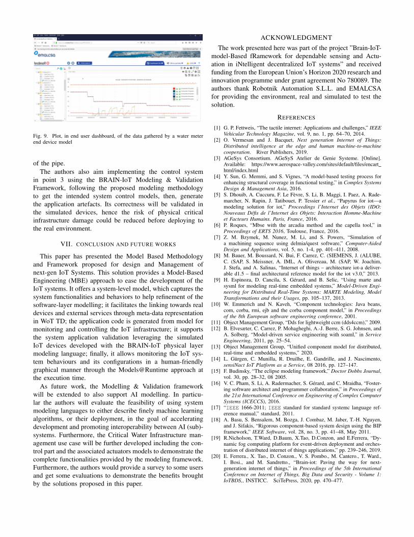
Fig. 9. Plot, in end user dashboard, of the data gathered by a water meterend device model
of the pipe.The authors also aim implementing the control system
in point 3 using the BRAIN-IoT Modeling & ValidationFramework, following the proposed modeling methodologyto get the intended system control models, then, generatethe application artefacts. Its correctness will be validated inthe simulated devices, hence the risk of physical criticalinfrastructure damage could be reduced before deploying tothe real environment.
VII. CONCLUSION AND FUTURE WORKS
This paper has presented the Model Based Methodologyand Framework proposed for design and Management ofnext-gen IoT Systems. This solution provides a Model-BasedEngineering (MBE) approach to ease the development of theIoT systems. It offers a system-level model, which captures thesystem functionalities and behaviors to help refinement of thesoftware-layer modelling; it facilitates the linking towards realdevices and external services through meta-data representationin WoT TD; the application code is generated from model formonitoring and controlling the IoT infrastructure; it supportsthe system application validation leveraging the simulatedIoT devices developed with the BRAIN-IoT physical layermodeling language; finally, it allows monitoring the IoT sys-tem behaviours and its configurations in a human-friendlygraphical manner through the Models@Runtime approach atthe execution time.
As future work, the Modelling & Validation frameworkwill be extended to also support AI modelling. In particu-lar the authors will evaluate the feasibility of using systemmodeling languages to either describe finely machine learningalgorithms, or their deployment, in the goal of acceleratingdevelopment and promoting interoperability between AI (sub)-systems. Furthermore, the Critical Water Infrastructure man-agement use case will be further developed including the con-trol part and the associated actuators models to demonstrate thecomplete functionalities provided by the modeling framework.Furthermore, the authors would provide a survey to some usersand get some evaluations to demonstrate the benefits broughtby the solutions proposed in this paper.
ACKNOWLEDGMENT
The work presented here was part of the project ”Brain-IoT-model-Based fRamework for dependable sensing and Actu-ation in iNtelligent decentralized IoT systems” and receivedfunding from the European Union’s Horizon 2020 research andinnovation programme under grant agreement No 780089. Theauthors thank Robotnik Automation S.L.L. and EMALCSAfor providing the environment, real and simulated to test thesolution.
REFERENCES
[1] G. P. Fettweis, “The tactile internet: Applications and challenges,” IEEEVehicular Technology Magazine, vol. 9, no. 1, pp. 64–70, 2014.
[2] O. Vermesan and J. Bacquet, Next generation Internet of Things:Distributed intelligence at the edge and human machine-to-machinecooperation. River Publishers, 2019.
[3] AGeSys Consortium. AGeSyS Atelier de Genie Systeme. [Online].Available: https://www.aerospace-valley.com/sites/default/files/encarthtml/index.html
[4] Y. Sun, G. Memmi, and S. Vignes, “A model-based testing process forenhancing structural coverage in functional testing,” in Complex SystemsDesign & Management Asia, 2016.
[5] S. Dhouib, A. Cuccuru, F. Le Fevre, S. Li, B. Maggi, I. Paez, A. Rade-marcher, N. Rapin, J. Tatibouet, P. Tessier et al., “Papyrus for iot—amodeling solution for iot,” Proceedings l’Internet des Objets (IDO:Nouveaux Defis de l’Internet des Objets: Interaction Homme-Machineet Facteurs Humains. Paris, France, 2016.
[6] P. Roques, “Mbse with the arcadia method and the capella tool,” inProceedings of ERTS 2016, Toulouse, France, 2016.
[7] Z. M. Bzymek, M. Nunez, M. Li, and S. Powers, “Simulation ofa machining sequence using delmia/quest software,” Computer-AidedDesign and Applications, vol. 5, no. 1-4, pp. 401–411, 2008.
[8] M. Bauer, M. Boussard, N. Bui, F. Carrez, C. (SIEMENS, J. (ALUBE,C. (SAP, S. Meissner, A. IML, A. Olivereau, M. (SAP, W. Joachim,J. Stefa, and A. Salinas, “Internet of things – architecture iot-a deliver-able d1.5 – final architectural reference model for the iot v3.0,” 2013.
[9] H. Espinoza, D. Cancila, S. Gerard, and B. Selic, “Using marte andsysml for modeling real-time embedded systems,” Model-Driven Engi-neering for Distributed Real-Time Systems: MARTE Modeling, ModelTransformations and their Usages, pp. 105–137, 2013.
[10] W. Emmerich and N. Kaveh, “Component technologies: Java beans,com, corba, rmi, ejb and the corba component model,” in Proceedingsof the 8th European software engineering conference, 2001.
[11] Object Management Group, “Dds for lightweight ccm (dds4ccm),” 2009.[12] B. Elvesæter, C. Carrez, P. Mohagheghi, A.-J. Berre, S. G. Johnsen, and
A. Solberg, “Model-driven service engineering with soaml,” in ServiceEngineering, 2011, pp. 25–54.
[13] Object Management Group, “Unified component model for distributed,real-time and embedded systems,” 2020.
[14] L. Gurgen, C. Munilla, R. Druilhe, E. Gandrille, and J. Nascimento,sensiNact IoT Platform as a Service, 08 2016, pp. 127–147.
[15] F. Budinsky, “The eclipse modeling framework,” Doctor Dobbs Journal,vol. 30, pp. 28–32, 08 2005.
[16] V. C. Pham, S. Li, A. Radermacher, S. Gerard, and C. Mraidha, “Foster-ing software architect and programmer collaboration,” in Proceedings ofthe 21st International Conference on Engineering of Complex ComputerSystems (ICECCS), 2016.
[17] “IEEE 1666-2011; IEEE standard for standard systemc language ref-erence manual,” standard, 2011.
[18] A. Basu, S. Bensalem, M. Bozga, J. Combaz, M. Jaber, T.-H. Nguyen,and J. Sifakis, “Rigorous component-based system design using the BIPframework,” IEEE Software, vol. 28, no. 3, pp. 41–48, May 2011.
[19] R.Nicholson, T.Ward, D.Baum, X.Tao, D.Conzon, and E.Ferrera, “Dy-namic fog computing platform for event-driven deployment and orches-tration of distributed internet of things applications,” pp. 239–246, 2019.
[20] E. Ferrera., X. Tao., D. Conzon., V. S. Pombo., M. Cantero., T. Ward.,I. Bosi., and M. Sandretto., “Brain-iot: Paving the way for next-generation internet of things,” in Proceedings of the 5th InternationalConference on Internet of Things, Big Data and Security - Volume 1:IoTBDS,, INSTICC. SciTePress, 2020, pp. 470–477.
89

AUTHOR INDEX
Annicchino, P. ............................................................ 19
Avgoustidis, H. .......................................................... 11
Baltazar, C. ................................................................ 38
Baouya, A. ............................................................. 3, 80
Battaglia, A. ............................................................... 11
Bednar, P. ................................................................... 25
Brun, P-E. ................................................................ 1, 3
Cantero, M. .................................................................. 2
Capparelli, F. .............................................................. 19
Cavallo, J. .................................................................. 11
Chehida, S. ............................................................. 3, 80
Chiappetta, A. ............................................................ 11
Christofi, S. ................................................................ 11
Conzon, D. ..................................................... 46, 55, 80
Diaz-Nava, M. ............................................................ 80
Ferrera, E. ............................................................ 46, 80
Goetz, J. ..................................................................... 80
Gonçalves, G. ................................................. 38, 55, 63
Hadjioannou,V. .......................................................... 11
Halas, P. ..................................................................... 25
Jeroschewski, S.E....................................................... 72
Kacmajor, M. ............................................................. 11
Kalompatsos, V. ......................................................... 11
Kristan, J. ................................................................... 72
Krousarlis, T. ............................................................. 11
Kulcsàr, G. ................................................................. 72
Loupos, K. ................................................................. 11
Maillet-Contoz, L. ..................................................... 80
Marcello, F................................................................. 31
Massot, G. .................................................................... 3
Michel, E. .................................................................. 80
Mygiakis, A. .............................................................. 11
Olotu, K. .................................................................... 72
Papageorgiou, A. ....................................................... 11
Pastrone, C. ................................................................ 55
Pereira, E. .................................................................. 63
Pilloni, V. ................................................................... 31
Plate, H. ....................................................................... 1
Prato, G. ..................................................................... 55
Reis, J............................................................. 38, 55, 63
Rossini, R................................................................... 55
Sarnovsky, M. ............................................................ 25
Seminara, S. ............................................................... 19
Skoufis, C. ................................................................. 11
Starynkevitch, B. ....................................................... 11
Tao, X. ................................................................. 46, 80
Theofilis, G. ............................................................... 11
Vedrine, F. ................................................................. 11
Yu, Y. ........................................................................ 46
Zavitsas, K. ................................................................ 11
Zemouri, S. ................................................................ 11
Zhao, R. ..................................................................... 46
90