ecn implementations in the ns simulator - icir · ecn implementations in the ns simulator sally...
TRANSCRIPT

ECN Implementations in the NS Simulator
Sally Floyd and Kevin Fall
Lawrence Berkeley National LaboratoryOne Cyclotron Road, Berkeley, CA 94720
[email protected], [email protected]
December 30, 1998
1 Introduction
This document illustrates the validation test for ECN (Explicit Congestion Notification) in the NS simulator [NS95].Figure 1 shows a single simulation with two-way traffic, showing the use of the CE (Congestion Experienced) bit
in the IP packet header, and the CWR (Congestion Window Reduction) and ECN-Echo bits in the TCP header. Werefer to a packet with the CE bit marked as a CE packet. Similarly, a CWR packet denotes a packet carrying a CWRnotification, and an ECN-Echo ACK packet denotes an ACK packet with the ECN-Echo bit set.
Figures 2 and 3 show that multiple CE packets in a window of data are considered as a single instance of congestion.Figures 4, 5, 6, and 7 show that interspersed dropped packets and CE packets are treated as a single instance of
congestion. While the behavior in these simulations is specific to Tahoe TCP, similar simulations in the test suiteshow that the same property holds for the Reno, NewReno, and Sack TCP implementations. Figures 8 and 9 are aseparate simulation scenario showing that interspersed dropped packets and CE packets are treated as a single instanceof congestion.
Figures 10, 11, and 12 show that interspersed dropped packets and CE packets are treated as a single instance ofcongestion even when the packet drops are sufficiently severe to result in a retransmit timeout. Figure 13 shows thatretransmitted packets with the CE bit set are interpreted as a new instance of congestion.
2 Running the tests in NS
All of the tests in this document can be run in the NS simulator with the commands “test-all-ecn” and “test-all-ecn-ack”in the tcl/test directory.
To run only a single simulation from the file “test-suite-ecn.tcl”, use the command:ns test-suite-ecn.tcl ecn nodrop tahoe
in the directory tcl/test. For each simulation, more detailed information about the simulation scenario can be found inthe simulation files “test-suite-ecn.tcl” and “test-suite-ecn-ack.tcl”
3 Interpreting the diagrams
The top diagram in each figure shows the data packets transmitted in a single TCP session. For each packet, there is amark when the packet arrives at the congested gateway, and a separate mark, possibly later, when the packet leaves thecongested gateway. For each mark, the x-axis shows the time, and the y-axis shows the packet number mod 90. Thereis an “X” for each dropped packet, an “X” enclosed in a box for each CE packet, and a solid diamond for each CWRpacket.
This work was supported by DARPA under DARPA grant DABT63-96-C-0105. This is a revised version of a document that was first madeavailable in October 1998.
1

Time
Pac
ket N
umbe
r (m
od 9
0)
0.0 0.5 1.0 1.5 2.0
020
4060
80
: data
.
.. .... ........ ....
..................................................................................................................................................................
....................................................................................................................................................................................
....................................................................................................................................................................................
........................................................................................................................................................................... : acks
: drops: CE: ECN-echo: CWR
Time
Con
gest
ion
Win
dow
0.0 0.5 1.0 1.5 2.0
1030
Figure 1: The test “ecn ack in the file “test-suite-ecn-ack.tcl”.
In addition, Figure 1 includes ACK packets. There is a small dot for each ACK packet arriving at the congestedgateway in the reverse direction, and a small open square for each ECN-Echo ACK packet.
The bottom diagram shows the TCP congestion window as a function of time.
4 An illustration of ECN-Echo packets
This test shows the data and ACK packets for an ECN-capable TCP connection. There are no packets dropped in thissimulation. Three separate packets have the CE bit, at times 1.2, 1.4, and 1.7. The bottom diagram shows that the TCPsender cuts the congestion window in half after each CE packet.
When the TCP receiver receives a data packet with the CE bit set, the receiver sets the ECN-Echo bit on returningACK packets. The receiver continues to set the ECN-Echo bit until it receives a data packet with the CWR bit set,indicating that the TCP sender has responded to congestion.
Test 1 uses Sack TCP, but Tahoe, Reno, and NewReno TCP show identical behavior for this scenario.
2

Time
Pac
ket N
umbe
r (m
od 9
0)
0.0 0.5 1.0 1.5 2.0 2.5 3.0
020
4060
80
: data: drops: CE: CWR
Time
Con
gest
ion
Win
dow
0.0 0.5 1.0 1.5 2.0 2.5 3.0
1030
Figure 2: The test “ecn nodrop tahoe”.
5 Multiple CE packets
This test shows TCP in an environment with no packet drops but with occasional ECN packets with the CE bit set.Tests 2 and 3 use Tahoe TCP, but for each test Reno, NewReno, and Sack TCP show identical behavior.
For this simulation, when the first packet has its CE bit set at time 1.2, there is a substantial queueing delay, asillustrated by the time between that packet's arrival and departure from the congested gateway. At time 1.5, a CWRpacket arrives at the congested gateway, indicating that the TCP sender has reduced its congestion window. Thisreduction in the congestion window can be seen in the bottom graph, and can also be seen visually in the reduction ofthe queueing delay at the congested gateway. For simplicity, these figures do not show the ACK packets.
3
Time
Pac
ket N
umbe
r (m
od 9
0)
0.0 0.5 1.0 1.5 2.0 2.5 3.0
020
4060
80
: data: drops: CE: CWR
Time
Con
gest
ion
Win
dow
0.0 0.5 1.0 1.5 2.0 2.5 3.0
1030
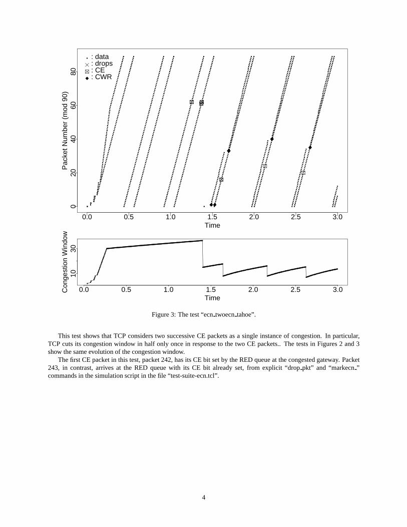
Figure 3: The test “ecn twoecn tahoe”.
This test shows that TCP considers two successive CE packets as a single instance of congestion. In particular,TCP cuts its congestion window in half only once in response to the two CE packets.. The tests in Figures 2 and 3show the same evolution of the congestion window.
The first CE packet in this test, packet 242, has its CE bit set by the RED queue at the congested gateway. Packet243, in contrast, arrives at the RED queue with its CE bit already set, from explicit “drop pkt” and “markecn ”commands in the simulation script in the file “test-suite-ecn.tcl”.
4

Time
Pac
ket N
umbe
r (m
od 9
0)
0.0 0.5 1.0 1.5 2.0 2.5 3.0
020
4060
80
: data: drops: CE: CWR
Time
Con
gest
ion
Win
dow
0.0 0.5 1.0 1.5 2.0 2.5 3.0
010
30
Figure 4: The test “ecn drop tahoe”.
6 Interspersed dropped packets and CE packets
This test shows that TCP considers a CE packet followed by a dropped packet as a single instance of congestion.Figures 4 through 6 all show the same evolution of the congestion window, with a single Slow-Start to recover froma combination of CE packets and dropped packets at time 1.3. Figures 4 through 9 show behavior specific to TahoeTCP. Similar simulations in the test suite show that Reno, NewReno, and Sack TCP implementations also respond tointerspersed packet drops and CE packets as a single instance of congestion.
For this scenario, the TCP sender reduces the Slow-Start threshold ssthresh and cuts its congestion window inhalf when it receives notification of the CE packet. The TCP sender subsequently Slow-Starts when it infers a packetloss from the receipt of three dup ACKs (duplicate acknowledgements). However, the Slow-Start is not accompaniedby a second reduction ssthresh.
The TCP sender reduces ssthresh to half the current congestion window or half the receiver's advertised window, whichever is smaller.
5
Time
Pac
ket N
umbe
r (m
od 9
0)
0.0 0.5 1.0 1.5 2.0 2.5 3.0
020
4060
80
: data: drops: CE: CWR
Time
Con
gest
ion
Win
dow
0.0 0.5 1.0 1.5 2.0 2.5 3.0
010
30
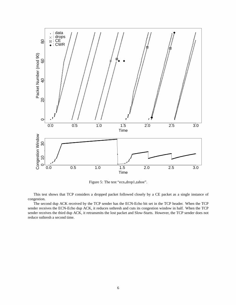
Figure 5: The test “ecn drop1 tahoe”.
This test shows that TCP considers a dropped packet followed closely by a CE packet as a single instance ofcongestion.
The second dup ACK received by the TCP sender has the ECN-Echo bit set in the TCP header. When the TCPsender receives the ECN-Echo dup ACK, it reduces ssthresh and cuts its congestion window in half. When the TCPsender receives the third dup ACK, it retransmits the lost packet and Slow-Starts. However, the TCP sender does notreduce ssthresh a second time.
6

Time
Pac
ket N
umbe
r (m
od 9
0)
0.0 0.5 1.0 1.5 2.0 2.5 3.0
020
4060
80
: data: drops: CE: CWR
Time
Con
gest
ion
Win
dow
0.0 0.5 1.0 1.5 2.0 2.5 3.0
010
30
Figure 6: The test “ecn drop2 tahoe”.
This test shows that even when the dropped packet and the CE packet are separated by a number of interveningpackets, Tahoe TCP considers the dropped packet and the following CE packet as a single instance of congestion. Inthis test the TCP sender learns of the CE packet after it has initiated Fast Recovery and Slow-Start.
The dropped packet and the CE packet in this scenario occur within a single window of data.
7

Time
Pac
ket N
umbe
r (m
od 9
0)
0.0 0.5 1.0 1.5 2.0 2.5 3.0
020
4060
80
: data: drops: CE: CWR
Time
Con
gest
ion
Win
dow
0.0 0.5 1.0 1.5 2.0 2.5 3.0
010
30
Figure 7: The test “ecn noecn tahoe”.
This test shows a single dropped packet, without any accompanying CE packet. In this test RED queue manage-ment has been disabled, to show the test without any CE packets. Up until time 2.0, Figure 7 shows the same evolutionof the congestion window as in Figures 4 through 6.
8

Time
Pac
ket N
umbe
r (m
od 9
0)
0.0 0.5 1.0 1.5 2.0 2.5 3.0
020
4060
80
: data: drops: CE: CWR
Time
Con
gest
ion
Win
dow
0.0 0.5 1.0 1.5 2.0 2.5 3.0
010
30
Figure 8: The test “ecn bursty tahoe”.
Figures 8 and 9 show that interspersed dropped packets and CE packets are treated as a single instance of conges-tion. Again, while the behavior in these simulations is specific to Tahoe TCP, similar simulations in the test suite showthat the same property holds for the Reno, NewReno, and Sack TCP implementations.
This test shows a burst of packet drops with no CE packets. The TCP sender recovers with a Fast Retransmit afterreceiving three dup ACKs. The Tahoe TCP sender reduces ssthresh and sets the congestion window to the defaultinitial value (in this case, one packet) to enter Slow-Start. The burst of back-to-back packets sent at time 1.6, when thesender receives an ACK packet sharply advancing the cumulative acknowledgement number, is allowed because theexperimental “maxburst” parameter to be turned off by default in NS.
9

Time
Pac
ket N
umbe
r (m
od 9
0)
0.0 0.5 1.0 1.5 2.0 2.5 3.0
020
4060
80
: data: drops: CE: CWR
Time
Con
gest
ion
Win
dow
0.0 0.5 1.0 1.5 2.0 2.5 3.0
010
30
Figure 9: The test “ecn burstyEcn tahoe”.
This test shows a CE packet followed by the same burst of packet drops as in Figure 8. When the TCP senderreceives the ECN-Echo ACK acknowledging the data in the CE packet, it resets ssthresh to half of the old congestion(or to half of the receiver's advertised window, whichever is smaller), and cuts its congestion window in half. There-fore, when the TCP sender receives three dup ACKS, it does not reduce ssthresh again, but only resets the congestionwindow to one to initiate Slow-Start.
10

Time
Pac
ket N
umbe
r (m
od 9
0)
0.0 0.5 1.0 1.5 2.0 2.5 3.0
020
4060
80
: data: drops: CE: CWR
Time
Con
gest
ion
Win
dow
0.0 0.5 1.0 1.5 2.0 2.5 3.0
010
30
Figure 10: The test “ecn timeout2 tahoe”.
7 Simulations with retreansmit timeouts
This test shows a large burst of packets being dropped, so that the TCP sender is forced to wait for a retransmit timeout.Tests 10, 11, and 12 use Tahoe TCP, but in each case tests with Reno, NewReno, and Sack TCP show identical
behavior.
11

Time
Pac
ket N
umbe
r (m
od 9
0)
0.0 0.5 1.0 1.5 2.0 2.5 3.0
020
4060
80
: data: drops: CE: CWR
Time
Con
gest
ion
Win
dow
0.0 0.5 1.0 1.5 2.0 2.5 3.0
010
30
Figure 11: The test “ecn timeout tahoe”.
This test is similar to Figure 10 except that a CE packet immediately precedes the burst of packet drops. Thecongestion window has a slightly different evolution from Figure 10 between times 1.4 and 1.9, but the two figuresshow the same evolution of the congestion window after time 1.9.
In this simulation, in response to an ACK packet with the ECN-Echo bit set that acknowledges the CE packet, TCPreduces ssthresh and reduces its congestion window by half. After the retransmit timeout, instead of reducing ssthreshagain, the TCP sender sets ssthresh to the current congestion window. Thus, TCP is not penalized twice for the CEpacket and the retransmit timeout.
12

Time
Pac
ket N
umbe
r (m
od 9
0)
0.0 0.5 1.0 1.5 2.0 2.5 3.0
020
4060
80
: data: drops: CE: CWR
Time
Con
gest
ion
Win
dow
0.0 0.5 1.0 1.5 2.0 2.5 3.0
010
30
Figure 12: The test “ecn timeout3 tahoe”.
This test is similar to Figure 10 except that a CE packet is interspersed among the burst of packet drops. Note thatthe congestion window has the same evolution as in Figure 11.
In this simulation, TCP reduces its congestion window by half in response to a duplicate ACK packet with theECN-Echo bit set, sent in response to the CE packet. After the retransmit timeout, instead of setting the variablessthresh to half the congestion window, the TCP sender sets ssthresh to the current congestion window.
13

Time
Pac
ket N
umbe
r (m
od 9
0)
0.0 0.5 1.0 1.5 2.0 2.5 3.0
020
4060
80
: data: drops: CE: CWR
Time
Con
gest
ion
Win
dow
0.0 0.5 1.0 1.5 2.0 2.5 3.0
010
30
Figure 13: The test “ecn timeout1 reno.
This test shows that a retransmitted packet with its CE bit set is interpreted by the TCP sender as a new instanceof congestion. This test uses Reno TCP.
This test contains a second TCP connection whose packets are not shown in this figure. Because of congestioncaused by the second TCP connection, a retransmitted packet from this TCP connection has its CE bit set at time 2.0.
14

Time
Pac
ket N
umbe
r (m
od 9
0)
0 1 2 3 4 5 6
020
4060
80
: data: drops: CE: CWR
Time
Con
gest
ion
Win
dow
0 1 2 3 4 5 6
510
15
Figure 14: The test “ecn smallwin tahoe.
8 ECN with small congestion windows
This test shows Tahoe TCP when successive packets are dropped while the congestion window equals one packet. Forthe first such drop, a retransmit timeout is required for recovery (because the sender does not receive three duplicateacknowledgements to initiate Fast Retransmit). In successive drops, the retransmit timeout is backed-off, using ex-ponential backoff. This exponential backoff of the retransmit timer is an essential component of TCP's congestioncontrol procedures, allowing robust operation in environments where the available bandwidth is less than one packetper roundtrip time.
15

Time
Pac
ket N
umbe
r (m
od 9
0)
0 2 4 6 8 10
020
4060
80
: data: drops: CE: CWR
Time
Con
gest
ion
Win
dow
0 2 4 6 8 10
010
20
Figure 15: The test “ecn smallwinEcn tahoe.
This test is similar to that in Figure 14, except that no packets are actually dropped. Successive packets have theCE bit set while the congestion window equals only one MSS-sized packet. TCP's congestion window is boundedbelow by one MSS. When the TCP sender receives an ECN-Echo packet and the congestion window is already onlyone MSS-sized packet, the TCP sender refrains from sending a new packet, and sets the retransmit timer. This figureshows the exponential backoff of the retransmit timer with successive CE packets.
An alternative implementation would be simply to allow the congestion window to be smaller than one MSS andto send smaller packets, and not to set the retransmit timer unless the congestion window is small relative to the packetheader size. While this approach merits investigation, we do not recommend it at this time, because this would allowECN-Capable TCP to be substantially more aggressive than non-ECN TCP during times of high congestion.
16
Time
Pac
ket N
umbe
r (m
od 9
0)
0.0 0.5 1.0 1.5 2.0
020
4060
80
: data: drops: CE: CWR
Time
Con
gest
ion
Win
dow
0.0 0.5 1.0 1.5 2.0
510
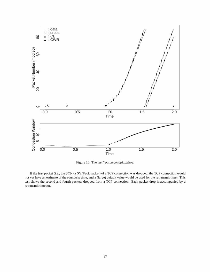
Figure 16: The test “ecn secondpkt tahoe.
If the first packet (i.e., the SYN or SYN/ack packet) of a TCP connection was dropped, the TCP connection wouldnot yet have an estimate of the roundtrip time, and a (large) default value would be used for the retransmit timer. Thistest shows the second and fourth packets dropped from a TCP connection. Each packet drop is accompanied by aretransmit timeout.
17

Time
Pac
ket N
umbe
r (m
od 9
0)
0.0 0.5 1.0 1.5 2.0
020
4060
80
: data: drops: CE: CWR
Time
Con
gest
ion
Win
dow
0.0 0.5 1.0 1.5 2.0
05
15
Figure 17: The test “ecn secondpktEcn tahoe.
In contrast to Figure 16, this test shows a TCP connection when the second and fourth packets have the CE bitset. After the first CE packet, there is no retransmit timeout, and the sender simply reduces the congestion windowfrom two to one packets. Therefore, when congestion is encountered while the congestion window is small, an ECN-Capable TCP connection can have a significant advantage over a non-ECN-Capable connection.
If the router decides to indicate congestion by dropping or marking a packet that is the first packet (i.e., the SYNor SYN/ack packet) of the TCP connection, the TCP end-nodes would not yet have negotiated ECN-Capability, andthat packet would not have the ECT bit set. Therefore, the router would have to drop rather than mark the packet, andthe TCP sender would have to wait for the retransmit timer to expire. Thus, ECN-capability does not help responsetimes for congestion encountered by the first packet of a TCP connection.
18

9 Conclusions
This note illustrates TCP's detailed response to ECN in the NS simulator. The response of TCP to ECN is describedmore generally in [ECN] and [Flo94].
References
[ECN] “The ECN Web Page,”. URL http://www-nrg.ee.lbl.gov/floyd/ecn.html.
[Flo94] S. Floyd. “TCP and Explicit Congestion Notification,”. ACM Computer Communication Review, 24(5):10–23, Oct. 1994.
[NS95] “NS (Network Simulator),”, 1995. URL http://www-mash.cs.berkeley.edu/ns/.
19