econoheat manual for vegetable oil heater
DESCRIPTION
EconoHeat Manual for Vegetable Oil HeaterTRANSCRIPT

Econo Heat♦5714 1st Avenue♦Spokane Washington 99212.♦(509)534-1022♦www.econoheat.com 100269 Rev A1
By
WASTE OIL FIRED BURNER WOB Series
Installation, Operation, And Service Instructions Manual
Thank you and congratulations on your purchase of an Omni Waste Oil Fired Burner. You have selected a high quality, precision-engineered piece of equipment, designed to give you many benefits as well as years
of outstanding performance.

2 Installation, Operation, And Service Instructions
PRECAUTIONS
Waste oil may contain many foreign materials. Waste oil may also contain gasoline. Therefore, specific precautions on the handling and storage of waste oils are to be observed when using, cleaning and maintaining this heater. Use a screen in a funnel when pouring oil into storage tank to catch foreign material, i.e., gasket material and sealant fibers, etc. WARNING: This appliance is not designated for use in hazardous atmospheres containing flammable vapors or combustible dust, or atmospheres containing chlorinated or halogenated hydrocarbons. Do not expose this unit to rain or moisture. If installed in high moisture atmosphere, a special cover for the integrated air compressor must be obtained from factory to avoid rusting of internal raw metals. If this occurs, see trouble-shooting guide for remedy. Uses only crank case oil, gear oil, hydraulic oils, auto trans. Fluid or #1 and #2 furnace oil. Do not use old, contaminated oils that have been stored in underground tanks or outside barrels for long periods. Excessive water and sludge may be present, causing quick filter plugging. NOTES: The instructions contained in this manual apply to the installation, operation, and service of Omni Waste oil fired burner. The following instructions should be carefully followed for obtaining the best possible installation, operation and service conditions. Specifications are subject to change without notice. This unit was designed to provide an economical disposal of waste oil. Proper operation depends on the consistency of the oil. Any water or foreign material in the oil may cause the unit to shut down. UNCRATING: Immediately upon uncrating units, check rating plate for certainty of electrical and mechanical characteristics. Also check the unit for any damage that may have been incurred in shipment, if any damage is found, file a claim with the transporting agency. The unit has been tested and inspected at the factory prior to crating and was in perfect condition at that time. If anything is missing check packing slip for indications of possible backorder of those parts or components. Otherwise a claim must be for those missing parts.
IMPORTANT NOTICE TO OWNER
AND INSTALLER To enjoy the long term benefits of burning your used oil in an Omni Waste Oil Burner, it is necessary to become familiar with the correct installation operation and maintenance of your new burner. Before installing or operating this appliance, make sure you read and understand this manual.
IMPROPER INSTALLATION OR LACK OF MAINTENANCE
WILL VOID THE WARRANTY
The most critical sections of this manual are in order of importance as follows: • Basic Operation Knowledge • Oil Suction Line Installation • Correct Draft Over Fire • General Maintenance Requirements Identical to any gas or oil burning appliance, without adequate draft over the fire, the combustion gases cannot escape the appliance. The flame will lengthen resulting in an overheated combustion chamber. Even if the heater is installed correctly and adequate draft achieved, a flue passage blockage will affect the draft. Burning used oil is similar to burning wood. A fine gray ash accumulates in the chamber and flue passage. This accumulation of ash will eventually affect the draft. It is important to remove this ash before the draft is affected. These topics are discussed in detail on the pages listed above. Please familiarize yourself with these sections of your manual. Spending a few minutes to review this material will assure that you receive the return on investment that you expect from your Omni heater.
Note: All illustrations and specifications contained herein are based on the latest information available at time of publication approval. Econo Heat reserves the right to make changes at any time without notice, in material and specifications.
Installation, Operation, And Service Instructions 3
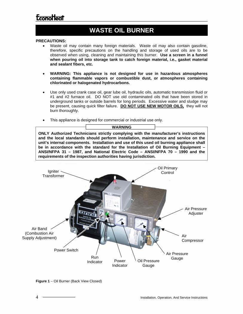
WASTE OIL BURNER PRECAUTIONS:
• Waste oil may contain many foreign materials. Waste oil may also contain gasoline, therefore, specific precautions on the handling and storage of used oils are to be observed when using, cleaning and maintaining this burner. Use a screen in a funnel when pouring oil into storage tank to catch foreign material, i.e., gasket material and sealant fibers, etc.
• WARNING: This appliance is not designed for use in hazardous atmospheres
containing flammable vapors or combustible dust, or atmospheres containing chlorinated or halogenated hydrocarbons.
• Use only used crank case oil, gear lube oil, hydraulic oils, automatic transmission fluid or
#1 and #2 furnace oil. DO NOT use old contaminated oils that have been stored in underground tanks or outside barrels for long periods. Excessive water and sludge may be present, causing quick filter failure. DO NOT USE NEW MOTOR OILS, they will not burn thoroughly.
• This appliance is designed for commercial or industrial use only.
ONLY Authorized Technicians strictly complying with the manufacturer’s instructions and the local standards should perform installation, maintenance and service on the unit’s internal components. Installation and use of this used oil burning appliance shall be in accordance with the standard for the Installation of Oil Burning Equipment – ANSI/NFPA 31 – 1987, and National Electric Code – ANSI/NFPA 70 – 1990 and the requirements of the inspection authorities having jurisdiction.
WARNING
Oil Primary Control Igniter
Transformer
Air Pressure Adjuster
Air Band (Combustion Air
Supply Adjustment)
h
Air Compressor
Air Pressure
Figure 1 –
4
Power Switc
Power Indicator
Run Indicator
Gauge Oil Pressure Gauge
Oil Burner (Back View Closed)
Installation, Operation, And Service Instructions
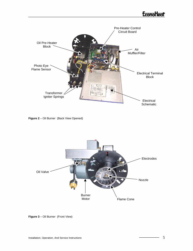
Air Muffler/Filter
Pre-Heater Control Circuit Board
Oil Pre-Heater Block
Photo Eye Flame Sensor
Electrical Terminal Block
Transformer Igniter Springs
Electrical Schematic
Figure 2 – Oil Burner (Back View Opened)
s
e
Figu
Instal
Oil Valv
e
Burner Motor
re 3 – Oil Burner (Front View)
lation, Operation, And Service Instructions
Flame Cone
Nozzl
Electrode
5

t
t
Figure 4 –Oil Pump Diagram
Figure 5 –Oil Pump Assembly
6 Installation, Operation, And Service Instructions
Oil Inle
Oil Outle

OIL BURNER TECHNOLOGY
Omni’s patented burner technology improves the efficiency of the oil burn process by continuous stabilization of the oil viscosity. Optimum atomization (spray) is accomplished by precisely pre-heating the oil and air prior to introduction to the combustion chamber. The waste oil enters into the Oil Pre-Heater Block (figure2) and is pre-heated to operating thermo setpoint, then compressed air from the air compressor (figure1) is mixed with the oil prior to spraying out the nozzle similar to fuel injection, by breaking up the oil droplets into a finer mist or spray (atomization). Electrodes mounted just above the nozzle (figure3) provides continuous electrical arc across electrode to electrode igniting the fine oil mist as it sprays out of the nozzle. Once ignited the flame is forced into a swirl caused by the burners blower and specially designed flame cone (figure3) providing a very efficient and thorough burn of the waste oil.
Burner Components
• Igniter Transformer: (figure1) Supplies high voltage to the electrodes generating electrical arc igniting the oil.
• Oil Valve: (figure3) energizes when burner is running and de-energizes when burner is not running eliminating bleed back of oil out of the Pre-heater block.
• Air Band: (figure1) Adjusts amount of air introduced into the combustion chamber.
• Oil Primary Control: (figure1) Controls the oil burner ignition. Checks for flame in the combustion chamber, if no flame is detected within 45 seconds, the oil primary will shutdown the oil burner. To restart the unit, reset the red button on the oil primary.
• Oil Pre-Heater Block: (figure2) Pre-heats the oil and air before entering combustion chamber.
• Photo Eye: (figure2) Senses flame in combustion chamber and signals oil primary when no flame is present.
• Igniter Springs: (figure2) Transfers the high voltage from the igniter transformer to the electrodes (when door is closed)
• Air Pressure Gauge: (figure1) Displays air pressure supplied by onboard air compressor.
• Air Compressor: (figure1) Supplies air used within pre-heater block to aid in atomization of the oil.
• Air Muffler/Filter: (figure2) Filters air and muffles the sound generated by the compressor.
• Pre-Heater Control Circuit Board: (figure2) Precisely controls temperature of the Oil Pre-Heater Block and controls safety feature of not allowing burner to energize until oil has established operating thermo setpoint or shutdown burner if Pre-Heater Block temperature falls below shutdown thermo setpoint.
• Electrodes: (figure3) Provides continuous high voltage electrical arc from electrode to electrode igniting the waste oil as it is being sprayed out of the nozzle.
• Nozzle: (figure3) Low pressure nozzle for oil spray pattern.
• Flame Cone: (figure3) Specially engineered flame cone forces the flame into a swirl pattern improving the burn thoroughness.
• Burner Motor: (figure3) Multitask motor turns the burner blower and integrated air compressor.
Installation, Operation, And Service Instructions 7

• Air Pressure Adjuster: (figure1) Adjusts the air pressure going to the pre-heater block. Should be adjusted between 12 PSI and 13PSI as indicated on the Air Pressure Gauge on the burner for thorough burn of the waste oil.
Note: In order to insure proper air adjustment, air gauge must read 0 when burner is cycled off or powered down.
• Oil Pressure Gauge: (figure1) Displays oil pressure at the burner. Adjustment at the Oil Pump must be made to achieve oil pressure readings at the burner as indicated below.
OMNI Model Oil Pressure Reading At Burner
OWB-9 1 PSI OWB-15 & OWH-150 2 PSI OWB-25 & OWH-250 4 PSI OWB-35 & OWH-350 6 PSI OWB-50 & OWH-500 11 PSI
• Power Indicator: (figure1) Indicates when power is present at the burner.
• Run Indicator: (figure1) Indicates that the burner is ready for operation after the initial pre-heat time of approx. 5 minutes from initial power up.
• Power Switch: (figure1) Switches power off and on to the burner. NOTE: Not applicable on OWH Series Furnaces.
8 Installation, Operation, And Service Instructions

TECHNICAL DATA
BURNER ASSEMBLY Performance Ratings Voltage - 115 VAC Cycles - 60Hz Total Operating Amperage (Burner Only) Amp 8.4 Total Operating Amperage (Burner and Oil Pump) Amp 10.5 Electrical Operating Consumption (Burner Only) Watts 970 Electrical Operating Consumption (Burner and Oil Pump) Watts 1,212 Weight Lbs 36.5 Oil Primary Amp 0.2 Oil Valve Amp 0.075 Pre-Heater Block Amp 4.2 Pre-Heater Controller Board Amp 0.011 Igniter Transformer Amp 0.3 Burner Motor Amp 3.6 PUMP ASSEMBLY Performance Ratings Voltage - 115Vac Cycles - 60Hz Total Operating Amperage (Pump Assy Only) Amps 2.1 Electrical Operating Consumption (Pump Assy Only) Watts 241.5 Weight Lbs 16 Oil Valve Amps 0.075 Pump Motor Amps 2.0
Installation, Operation, And Service Instructions 9
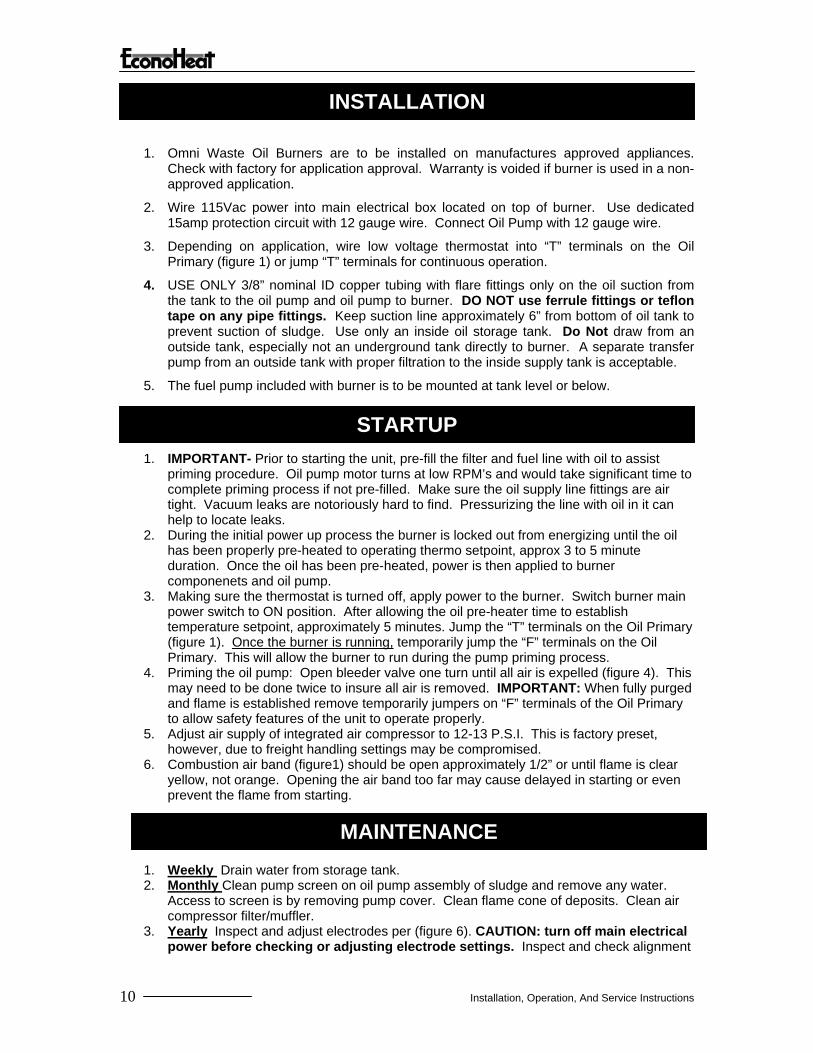
INSTALLATION
1. Omni Waste Oil Burners are to be installed on manufactures approved appliances. Check with factory for application approval. Warranty is voided if burner is used in a non-approved application.
2. Wire 115Vac power into main electrical box located on top of burner. Use dedicated 15amp protection circuit with 12 gauge wire. Connect Oil Pump with 12 gauge wire.
3. Depending on application, wire low voltage thermostat into “T” terminals on the Oil Primary (figure 1) or jump “T” terminals for continuous operation.
4. USE ONLY 3/8” nominal ID copper tubing with flare fittings only on the oil suction from the tank to the oil pump and oil pump to burner. DO NOT use ferrule fittings or teflon tape on any pipe fittings. Keep suction line approximately 6” from bottom of oil tank to prevent suction of sludge. Use only an inside oil storage tank. Do Not draw from an outside tank, especially not an underground tank directly to burner. A separate transfer pump from an outside tank with proper filtration to the inside supply tank is acceptable.
5. The fuel pump included with burner is to be mounted at tank level or below.
STARTUP 1. IMPORTANT- Prior to starting the unit, pre-fill the filter and fuel line with oil to assist
priming procedure. Oil pump motor turns at low RPM’s and would take significant time to complete priming process if not pre-filled. Make sure the oil supply line fittings are air tight. Vacuum leaks are notoriously hard to find. Pressurizing the line with oil in it can help to locate leaks.
2. During the initial power up process the burner is locked out from energizing until the oil has been properly pre-heated to operating thermo setpoint, approx 3 to 5 minute duration. Once the oil has been pre-heated, power is then applied to burner componenets and oil pump.
3. Making sure the thermostat is turned off, apply power to the burner. Switch burner main power switch to ON position. After allowing the oil pre-heater time to establish temperature setpoint, approximately 5 minutes. Jump the “T” terminals on the Oil Primary (figure 1). Once the burner is running, temporarily jump the “F” terminals on the Oil Primary. This will allow the burner to run during the pump priming process.
4. Priming the oil pump: Open bleeder valve one turn until all air is expelled (figure 4). This may need to be done twice to insure all air is removed. IMPORTANT: When fully purged and flame is established remove temporarily jumpers on “F” terminals of the Oil Primary to allow safety features of the unit to operate properly.
5. Adjust air supply of integrated air compressor to 12-13 P.S.I. This is factory preset, however, due to freight handling settings may be compromised.
6. Combustion air band (figure1) should be open approximately 1/2” or until flame is clear yellow, not orange. Opening the air band too far may cause delayed in starting or even prevent the flame from starting.
MAINTENANCE 1. Weekly Drain water from storage tank. 2. Monthly Clean pump screen on oil pump assembly of sludge and remove any water.
Access to screen is by removing pump cover. Clean flame cone of deposits. Clean air compressor filter/muffler.
3. Yearly Inspect and adjust electrodes per (figure 6). CAUTION: turn off main electrical power before checking or adjusting electrode settings. Inspect and check alignment
10 Installation, Operation, And Service Instructions

of nozzle in relation to flame cone/burner tube (figure 6). Tip of nozzle must be 1/4” forward of inside radius of flame cone. If nozzle is behind inside radius of flame cone, coking will occur and flame cone can clog. To adjust, loosen Pre-Heater block securing nut and set screw, push fore or aft as needed then retighten securing nut and set screw.
Figure 6 –Electrode Adjusment Diagram
When cleaning, inspect all three pieces thoroughly. When disassembling and reassembling nozzle, keep facing up as shown.
Figure 7 –Nozzle Assembly Detail
Installation, Operation, And Service Instructions 11

BLK
BLU
WHT
RE
D
YE
L
BLK
OR
N
BLK
OIL PREHEATER BLOCK
CONTROLLER WHT
RED
HTR
PR
I
L2
L1
BLOWER MOTOR
WH
T
GRN
HIGH VOLTAGE TRANS-
FORMER
BLK
PHOTO EYE FLAME SENSOR
OIL PRIMARY CONTROL (IE, Honeywell, etc.)
BLK
OR
N
WH
T
THERMOSTAT CONNECTION
BURNER DOOR
SAFETY PLUG
500W HEAT ROD
Bi METAL HIGH LIMIT SWITCH
THERMO-COUPLE
OIL PREHEATER
BLOCK
Fuse Power Switch
BLK
BLK
WH
T
WH
T
RE
D
WH
T
WH
T
WH
T
RE
D
BLU
Figure 8 –Burner Wiring Diagram
12 Installation, Operation, And Service Instructions

Omni Burner Assembly
Limited Warranty Econo Heat (manufacturer) warrants to the purchaser of Burner Assembly will be free from
defects in materials and workmanship for the durations specified below, which duration begins on the date of purchase by the customer. Customer is responsible for maintaining proof of date of
purchase. If return is deemed necessary for repair or replacement, unit is to be sent to the factory freight prepaid for evaluation and warranty determination. Econo Heat reserves the right
to determine appropriate action for repair or replacement.
1. Oil Heater Block, twenty (20) years. (Parts Only) 2. Oil Heater Block Controller PCB, three (3) years. (Parts Only) 3. All other components, one (1) year. (Parts Only)
This warranty is void if:
1. Warranty registration card is not returned within thirty (30) days of purchase. 2. Any part or component subject to abuse or altered from original manufactures specifications. 3. Installation not in accordance with instructions or has not been properly maintained. 4. Wiring not in accordance with diagram furnished with burner. 5. Burner is operated in the presence of chlorinated vapors.
Warranty is limited to the original purchaser. The above warranty is in lieu of all other warranties expressed or implied. Econo Heat does not authorize any person or representative to make or assume any other obligation or liability that is not in accordance with above warranty. Econo Heat is not responsible for any labor cost unless prior authorization in writing has been obtained.
No parts will be accepted by Econo Heat without RA# (return authorization number) clearly marked on outside of shipping package. Obtaining RA# requires model and serial numbers, description of part being replaced and nature of defect.
WARRANTY CARD Please fill our, tear off and return to manufacturer
Return following warranty information to manufacturer within thirty (30) days of purchase or warranty will not be valid. (Please print or type). Date of Purchase_____________________________________________________________________ Serial #__________________________ Model ____________________________________________ Customer Name_____________________________________________________________________ Address____________________________________________________________________________ City _________________________ State ________________ Zip Code ________________________ Dealer ____________________________________________________________________________ Address ___________________________________________________________________________ City_________________________ State _________________ Zip Code _______________________ Installed at ________________________________________________________________________
Installation, Operation, And Service Instructions 13