economic dispatch by secondary distributed control in
TRANSCRIPT

Economic Dispatch by Secondary Distributed Control in Microgrids
Jacqueline Llanos1 2, Juan Gomez1, Doris Saez1, Daniel Olivares3 and John Simpson-Porco4
1 University of Chile, Santiago, Chile.2 Universidad de las Fuerzas Armadas ESPE, Sangolquı, Ecuador.
3 Pontificia Universidad Catolica de Chile, Santiago, Chile.4 University of Waterloo, Waterloo, Canada
Email: [email protected], [email protected]
AcknowledgmentsThis study was supported by FONDECYT Project 1170683, FONDECYT Project 1181517, the Com-plex Engineering Systems Institute (CONICYT/FB0816), the Solar Energy Research Center SERC-Chile(CONICYT/FONDAP/15110019) and Ph.D. scholarship from CONICYT Doctorado para Extranjeros/2015-21150555/2014-63140113.
KeywordsSmart microgrids,Microgrid,Energy system management,Smart grids,Distributedpower,Power management
AbstractThis paper proposes a distributed controller in order to achieve the economic dispatch (ED) of a micro-grid, which complies with the Karush-Kuhn-Tucker optimality conditions for a linear optimal power flowformulation. The consensus over the Lagrange multipliers allows an optimal dispatch without consider-ing an electrical microgrid model, preserving the frequency and voltage restoration into the secondarycontrol level for isolated microgrids.
IntroductionWith the increased penetration of Distributed Generation (DG) units based on renewable energy resourcesand distributed energy storage (DES) units, the microgrids have emerged as systems that allow the inte-gration of these units. A microgrid is described as a cluster of DG units, DES units, and distributed loads,coordinated to supply electricity in order to fulfill economic, technical, and environmental requirements.The microgrids can operate in a grid-connected mode using a Point of Common Coupling (PCC) or inan isolated mode [1].
The microgrid, in general, assumes three critical functions: the control of the DG units, the energymanagement, and the protections of the microgrid [2]. A three level hierarchical control structure is used.The primary control maintain voltage and frequency stability, deviating the operation values when thepower demanded changes, this level includes the inner control loops and droop control. The secondarycontrol restores the frequency and the voltage to their nominal values, and the tertiary control achievesthe optimal dispatch of the microgrid, and it manages the power flow between the microgrid and themain grid in grid-connected mode [1] [3] [4]. In the hierarchical architecture, the primary control isperformed within a shorter time scale compared to the secondary control; while the optimal dispatchrequires several minutes depending on the complexity of the optimization problem to be solved [5].
The existing secondary control strategies can be classified into three control approaches: centralized,decentralized, and distributed control. In the first approach, the central controller uses measurementsfrom the whole microgrid to compensate the frequency and voltage deviations, however if the centralcontroller fails the frequency/voltage restoration are not achieved.

The decentralized and distributed approaches are usually based on PI controllers in order to restorethe frequency and the voltage [4] [7]. Decentralized approach uses just local measurements to achievethe regulation, whereas distributed approach uses information from neighbors DG units, requiring acommunication network and increasing reliability and security in isolated microgrids [3] [6]. Nowadaysa consensus algorithm is included to the distributed approach improving the real and reactive powersharing [5] [8].
The optimal operation is a tertiary control level task, and it is achieved by solving an economic dispatchproblem. This controller is often formulated under a centralized approach, and requires several minutesto solve an optimization problem. However, in microgrids, the disturbances can be produced at seconds,then the optimal dispatch is not updated for this time scale. In order to solve the optimal dispatch atshorter times, it can be analyzed with decentralized or distributed control approaches.
The adaptive droop controller is a common technique used to achieve minimal operation cost basedon decentralized schemes [9] and [10]. In this scheme, the DGs controllers are tuned according to itsgeneration cost. However, due the DGs do not share information, the global minimum generation cost isnot achieved in the microgrid.
Some techniques used for minimal cost based on distributed control approach are the following: incre-mental cost consensus estimated (ICC) [11], [12], and gradient consensus [13], [14]. The ICC is usedin Multi-Agent System (MAS) [11], and it is based on consensus algorithm and incremental cost (IC).IC and global supply-demand mismatch are estimated for each generator [16], however, these works donot consider the generating power limits. In [11], [12], [17] external controllers are added in order toconsider the power generating limits applying ICC approach, in these cases a pseudo generating cost forDG neighbors is estimated. Unlike ICC, the distributed gradient approach computes the incremental cost[13], [18]. All these works include the IC as the consensus variable.
Unlike the works above mentioned, our controller includes the Karush-Kuhn-Tucker (KKT) conditionsfrom a centralized linear optimal power flow (OPF) formulation considering the generating power limits,using a distributed scheme. Our proposal is based on the distributed-averaging proportional-integral(DAPI) controller for frequency and voltage restoration proposed in [8]. We add an additional controllerto the DAPI frequency loop to achieve the optimal economic dispatch of the microgrid. Notice that thedesign of this additional controller is a contribution itself. In order to the whole microgrid satisfy the KKTconditions, the DG units exchange information with their respective neighbors using a communicationnetwork.
The experimental results validate the adequate performance of the controller against sudden changesin the load and communication failures, the microgrid performance when a DG unit is disconnected istested as well.
The contributions of this paper are as follow: i) the optimal dispatch and frequency restoration areconsidered in the same time scale in order to archive the optimal dispatch when fast disturbances occur,ii) the KKT optimality conditions of the linear centralized OPF problem are satisfied, iii) the microgridtopology is not required for achieve the optimal dispatch, iv) the proposed controller was tested in aexperimental microgrid.
Economic Dispatch by Secondary Distributed Control in MicrogridsThe design of the proposed distributed controller is based on a centralized optimal economic dispatchformulation and the KKT optimal conditions. A consensus algorithm over the Lagrange multipliersrelated to real power balance is considered as well. The proposed approach is described in detail below.
Average Consensus Algorithm
Consider the graph G = (N ,E ,A), where N = 1, ..,n is the vertex set that represents the DG unitsin the microgrid, E ⊂ N ×N represents the edge set of communication links between DGs, and Ais the n× n adjacency matrix of the graph. If DG i ∈ N exchanges information with DG j ∈ N , then

ai j = a ji = 1, otherwise ai j = 0. It is said that the consensus over variable x is achieved if xi(t)−x j(t)→ 0for all vertices i, j ∈N . If G is connected, consensus is achieved via the first-order consensus algorithmxi =−∑ j∈N , j 6=i ai j(xi− x j); see [8].
Centralized Optimal Economic Dispatch
Prior to the distributed controller proposal design, a centralized optimal economic dispatch and its KKToptimality conditions are presented, which are used in the design of the controller proposed. We considera balanced-load microgrid, with a set of DGs N = 1, . . . ,n, each one with a different operation costdefined as a function of its real power Ci(Pi). In order to achieve the optimal economic dispatch a linearpower flow formulation, based on a single-bus system, is designed as is shown in (1). The objectivefunction (1a) is defined to minimize the operation cost of the microgrid; where Ci(Pi) is a convex costfunction defined by Ci(Pi) = aiP2
i +biPi+ci, Pi is the real power dispatched for the generator i, and ai, bi,and ci, are the parameters function cost. The optimization problem is subject to power balance constraintby (1b), where PD is the power demanded. The power limits of DGs constraint are defined in (1c).
minimize ∑i∈N Ci(Pi) (1a)
subject to PD = ∑i∈N Pi (1b)
Pmini ≤ Pi ≤ Pmax
i ∀ i ∈N (1c)
The Lagrangian function of optimal dispatch problem (1) is shown in (2)
L(Pi,λ,σ+i ,σ
−i ) = ∑
i∈NCi(Pi)+λ
(PD− ∑
i∈NPi
)+ ∑
i∈Nσ+i (Pi−Pmax
i )+ ∑i∈N
σ−i (P
mini −Pi) (2)
Where λ represents the Lagrange multiplier associated to power balance constraint (1b), σ−i and σ
+i are
the Lagrange multipliers associated to minimum and maximum power constraints (1c).
Notice that in the distributed proposal design, we consider the Lagrange multipliers σ+i as the control
action related to the maximum power limits of the DG unit, and Lagrange multipliers σ−i represents the
control action related to the minimum power limits of the generating unit.
The KKT optimality conditions of the optimization problem (1) are defined as follow:
∂L∂Pi
= ∇Ci(Pi)−λ+σ+i −σ
−i = 0 i ∈N (3a)
σ+i (Pi−Pmax
i ) = 0 i ∈N (3b)
σ−i (P
mini −Pi) = 0 i ∈N (3c)
σ+i , σ
−i ≥ 0 i ∈N (3d)
The primal feasibility conditions are defined by (1b) (1c).
Distributed Control Design
The proposed controllers have the following features: i) The secondary control and the optimal economicdispatch are solved in the same time scale, ii) The distributed control approach is used, iii) The optimaldispatch is achieved using PI controllers, iv) The real-time measurements are used in order to obtainthe economic optimal dispatch, v) The control actions for frequency regulation and optimal dispatchare added to the droop controller, vi) The communication network is connected, bidirectional and ideal(without large time-delays). vii) The communication topology is different from the electrical networktopology.
Secondary control and the optimal economic dispatch need to be solved in the same time scale. The firststage comprises the design of secondary control for frequency and voltage restoration, then in the secondstage a new term is added in order to achieve the economic dispatch.

Distributed Secondary Control
The frequency restoration is achieved using the DAPI controller proposed in [8], it is shown in (4)–(5), where mi is P−ω droop coefficient, Pi is the real power injection, ω∗ is the nominal frequency andωi corresponds to frequency regulated in the ith DG. The DAPI control action Ωi is obtained from (5),where the terms ai j are the entries of the adjacency matrix; thus, the control action Ω j is shared withgenerator i only if ai j is nonzero.
ωi =ω∗−miPi +Ωi (4)
kiΩi =− (ωi−ω∗)−∑ j∈N , j 6=i ai j(Ωi−Ω j) (5)
Also, DAPI voltage-regulation and reactive-power-sharing controllers are implemented based on [8].The control law of this controller is represented by equations (6) and (7), where ei is the control actionfor voltage regulation, Ei is the voltage of the ith DG, ni represents the Q-E droop coefficient, E∗ is themicrogrid nominal voltage, Q∗i is the reactive power rating of unit i, βi and ki are positive gains, andai j is an element of the adjacency matrix of communication between DGs. In this case ei establishes atrade-off between voltage regulation and reactive power sharing.
Ei = E∗−niQi + ei (6)
kiei =−βi (Ei−E∗)−bi ∑ j∈N ,, j 6=i ai j
(Qi
Q∗i−
Q j
Q∗j
)(7)
Distributed Secondary and Economic Dispatch ControlIn order to achieve the optimal economic dispatch the droop frequency ωi in (4) is modified. As is shownin (8) the term ρi is added, and its design is based on the centralized optimal economic dispatch (1).
ωi = ω∗−mi(Pi)+Ωi +ρi (8)
We include the first KKT optimality condition (3a) in the proposed controller obtaining the λi multiplieras is shown in (9).
λi = ∇Ci(Pi)+σ+i −σ
−i (9)
Notice that λi is related to the power balance in the microgrid and it should be equal to λ multiplier on(3a) in order to achieve a global balance. Then in the distributed scheme, a consensus algorithm overwhole λi multipliers is defined in (10), where ρi is considered as the consensus control action.
k1i ρi =−∑ j∈N , j 6=i ai j(λi−λ j) (10)
The Lagrange multipliers from the centralized optimal economic dispatch are represented as controlactions in the proposed distributed controllers. In this context the σ
+i distributed controller shown in (11)
is designed to ensure the operation below the maximum limit of real power generation. This controlleris activated if the active power in the DGi is greater than its maximum limit, and the term k3
i σ+i is added
in order to guarantee that σ+i = 0, achieving the same performance of the multipliers in the centralized
problem, if this constraint is not activated. σ−i distributed controller shown in (12) is designed to ensure
the operation over the minimum limits of real power generation in all DG units, this controller is designedin the same way than σ
+i controller.
k2i σ
+i = µ2
i max
Pi +1µ2
ik3
i σ+i −Pmax
i ,0− k3
i σ+i (11)
k4i σ−i = µ3
i max
Pmini +
1µ3
ik5
i σ−i −Pi,0
− k5
i σ−i (12)

The stationarity centralized KKT condition (3a) is satisfied through (9) in the distributed controller, thecomplementary slackness constraints (3b) and (3c) are satisfied by (11) and (12) respectively. The dualfeasibility contraints (3d) are satisfied by (11) and (12). Finally the primal feasibility condition definedby (1b) is satisfied by (5), and the primal feasibility condition defined by (1c) is satisfied by (11) and(12).
Distributed Secondary and Economic Dispatch Control SchemeFig. 1 shows the architecture of the local controller implemented in each DG that enables the distributedcontrol strategy. The first layer corresponds to voltage and current control, also a virtual impedance isadded for microgrids with resistive lines [15]. The second layer correspond to primary control droop,where the terms of the equations (8) and (6) are calculated using local measurements. The equation(6) and (8) are modified by the third control layer. This layer includes the distributed controllers forfrequency and voltage restoration and economic dispatch. We added the term Ωi from (5) in order toachieve frequency restoration, and ρi in order to achieve the economic dispatch of the microgrid, this isobtained from (9), (10), (11) and (12).
The proposed controller receives from each neighbor j the following information: Ω j,λ j,Q j and Q∗j ,while it sends Ωi,λi,Qi and Q∗i . The exchange of information between local DG controllers occursthrough the communication network.
Fig. 1: Distributed control scheme
Experimental ResultsIn order to validate the proposed controllers, experimental tests were performed in the Laboratory of Mi-crogrids Control at the University of Chile shown in Fig. 2. The microgrid topology is composed of threeconverters, two local loads and two power lines. The characteristics of DG units and network parametersare given in Table I and Table II, respectively. Ethernet communication network is implemented to shareinformation among DGs, as is shown at left side of Fig. 2, and it is able to emulate a communicationfailure. The topologies, as well as the adjacency matrix A, with and without failure, are shown in Fig. 3.
In this work different operating costs of each DG are considered, DG 2 has the lowest operating cost andDG 3 is the more expensive, the generating cost function (13) of each DG unit is assumed quadratic, the

Table I: DG characteristics
Parameter Symbol DG1-DG3Max Active Power Pmax
i 2kWMin Active Power Pmin
i 0kWP-W Droop Coefficient mi 2.5·10−3 rad
W·sQ-E Droop Coefficient ni 1.5·10−3 V
varFrequency Control Gain ki 0.5s
Voltage Control Gain ki 1sOD Control Gain k1
i 0.5sMax Power Control Gain k2
i 0.1sMin Power Control Gain k4
i 0.1s
Return to Zero Gain k3i
u2i, k5
iu3
i0.01s
Table II: Microgrid parameters
Parameter Symbol ValueNominal Frequency ω∗/2π 50 Hz
Nominal Voltage E∗ 150 VFilter Capacitance C 25µFFilter Inductance L f 1.8mH
Coupling Inductance Lo 2.5mHSampling Period TSP 1/16E3 S
Load 1 L1 11Ω
Load 2 L2 22Ω
Line Impedance Li j 2.5mHCutoff f−Droop filter ωc 1*2π rad/S
parameters used in this work are shown in Table III.
Ci(Pi) = aiP2i +biPi + ci (13)
Three operating scenarios are evaluated. i) Load impacts scenario. ii) Communication links failuresscenario, where a failure of the communication link between DG 1 and DG 3 is produced (See Fig. 3b).iii) Controller performance when the DG 3 is disconnected of the microgrid.
1
Converter 1 Converter 2
Converter 3
𝐿12
𝐿23
Z1
Z2
𝐿0
Communication Controller 1
Controller 2
Controller 3
Loads
DG 1
DG 2
DG 3
𝐿0
𝐿0
Fig. 2: Microgrid experimental setup
Fig. 3: Microgrid communication topology a) Original topology b) Topology with communication linksfailure
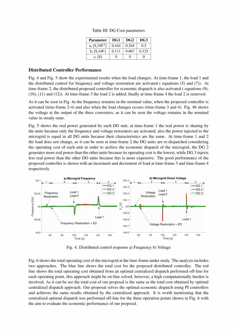
Table III: DG Cost parameters
Parameter DG1 DG2 DG3ai [$/kW 2] 0.444 0.264 0.5bi [$/kW ] 0.111 0.067 0.125
ci [$] 0 0 0
Distributed Controller Performance
Fig. 4 and Fig. 5 show the experimental results when the load changes. At time-frame 1, the load 1 andthe distributed control for frequency and voltage restoration are activated ( equations (5) and (7)). Attime-frame 2, the distributed proposed controller for economic dispatch is also activated ( equations (9),(10), (11) and (12)). At time-frame 3 the load 2 is added, finally at time-frame 4 the load 2 is removed.
As it can be seen in Fig. 4a the frequency remains in the nominal value, when the proposed controller isactivated (time-frame 2-4) and also when the load changes occurs (time-frame 3 and 4). Fig. 4b showsthe voltage at the output of the three converters, as it can be seen the voltage remains in the nominalvalue in steady-state.
Fig. 5 shows the real power generated by each DG unit, at time-frame 1 the real power is sharing bythe units because only the frequency and voltage restorators are activated, also the power injected to themicrogrid is equal in all DG units because their characteristics are the same. At time-frame 1 and 2the load does not change, as it can be seen at time-frame 2 the DG units are re-dispatched consideringthe operating cost of each unit in order to archive the economic dispatch of the microgrid, the DG 2generates more real power than the other units because its operating cost is the lowest, while DG 3 injectsless real power than the other DG units because this is more expensive. The good performance of theproposed controller is shown with an increment and decrement of load at time-frame 3 and time-frame 4respectively.
60 80 100 120 140 160
Time [s]
49.9
49.95
50
50.05
50.1
Fre
qu
en
cy [
Hz]
a) Microgrid Frequency
DG 1
DG 2
DG 3
60 80 100 120 140 160
Time [s]
149.6
149.7
149.8
149.9
150
150.1
150.2
150.3
150.4
Vd [
V]
b) Microgrid Direct Voltage
DG 1
DG 2
DG 3
2 3 41 2 3 4 1
Frequency
Restoration
Load 1
Load 2
Frequency Restoration + ED Voltage Restoration + ED
Load 1
Load 2Voltage
Restoration
Load 1Load 1
Fig. 4: Distributed control response a) Frequency b) Voltage
Fig. 6 shows the total operating cost of the microgrid at the time-frame under study. The analysis includestwo approaches. The blue line shows the total cost for the proposed distributed controller. The redline shows the total operating cost obtained from an optimal centralized dispatch performed off-line foreach operating point, this approach might be on-line solved, however, a high computationally burden isinvolved. As it can be see the total cost of our proposal is the same as the total cost obtained by optimalcentralized dispatch approach. Our proposal solves the optimal economic dispatch using PI controllersand achieves the same results obtained by the centralized approach. It is worth mentioning that thecentralized optimal dispatch was performed off-line for the three operation points shown in Fig. 6 withthe aim to evaluate the economic performance of our proposal.

60 80 100 120 140 160Time [s]400
600
800
1000
1200
1400
1600
1800
2000
Re
al P
ow
er
[W]
Microgrid Real Power
DG 1
DG 2
DG 3
Load 1
DG 1=691 W
DG 2=691 W
DG 3=691 W
Total=2073 W
1 2 3 4
Load 1
Load 2DG 1=581 W
DG 2=976 W
DG 3=516 W
Total=2073 W
Load 1
Fig. 5: Distributed control response - Real Power
70 80 90 100 110 120 130 140 150 160 170
Time[s]
2
3
4
Op
era
tin
g C
ost
[$]
×10-4 Operating Cost
Distributed ED
Centralized ED
Fig. 6: Operating cost
Communication link failure
Fig. 7 and Fig. 8 show the performance of the proposed distributed controller when a communication linkfailure occurs. At time-frame 1, load 1, and all controller proposed (frequency and voltage restorationand economic dispatch) are activated, at time-frame 2 the communication link between DG 1 and DG 2fails (Fig. 3b). Finally at time-frame 3 an incremental of load is produced (load 1 and load 2). As it can beseen the frequency ( Fig. 7a) and voltage ( Fig. 7b) remain in the nominal value when the communicationlink failure is produced.
In Fig. 8, the real power does not change when a communication link failure is produced (time-frame 2),because the controller detects the change in the communication network topology through the adjacencymatrix, which is included in the consensus algorithm of the controller. Notice that the communicationnetwork topology is connected when the fail is produced.
Disconnection of a DG unit
In this scenario the DG 3 is disconnected, the results are shown in Fig. 9 and Fig. 10. During the time-frame 1 the proposed controllers (frequency and voltage restoration and economic dispatch) are activated,at time-frame 2 the DG 3 is disconnected, finally at time-frame 3 the load is increased.
In Fig. 9a and Fig. 9b the frequency and voltage are restored respectively to the nominal value whenthe disconnection of DG 3 is produced (time-frame 2 and time-frame 3). Fig. 10 shows the results ofthe real power injected, at time-frame 2 when the DG 3 is disconnected the real power is re-dispatchedconsidering the operating cost of each DG, thus the DG 2 supplies more real power than DG 1 becausethe operating cost of DG 2 unit is lower. In order to validate the controller performance when a DGunit is disconnected an incremental load is produced (time-frame 3). As it can be seen the frequencyand voltage are restored to their nominal values, at the same time the operating cost of DG units areconsidered.

60 80 100 120 140 160
Time [s]
49.9
49.95
50
50.05
50.1
Fre
qu
en
cy [
Hz]
a) Microgrid Frequency
DG 1
DG 2
DG 3
60 80 100 120 140 160
Time [s]
149.6
149.7
149.8
149.9
150
150.1
150.2
150.3
150.4
Vd [
V]
b) Microgrid Direct Voltage
DG 1
DG 2
DG 3
1 32 2 31
Communication link failureLoad 1
Load 2Load 1
Load 2
Communication link failure
Fig. 7: Distributed control response test by communication link failure a) Frequency b) Voltage
60 80 100 120 140 160
Time [s]
0
500
1000
1500
2000
Re
al P
ow
er
[W]
Microgrid Real Power
DG 1
DG 2
DG 3
21 3
Load 1
Load 2Communication link failure
Fig. 8: Distributed control response test by communication link failure - Real Power
60 80 100 120 140 160
Time [s]
49.9
49.95
50
50.05
50.1
Fre
qu
en
cy [
Hz]
a) Microgrid Frequency
DG 1
DG 2
DG 3
60 80 100 120 140 160
Time [s]
149.6
149.7
149.8
149.9
150
150.1
150.2
150.3
150.4
Vd [
V]
b) Microgrid Direct Voltage
DG 1
DG 2
DG 3
DG 3 Disconnection
DG 3 Disconnection
Load 2Load 1
Load 2
1 2 1 2 33
Load 1
Load 2
Fig. 9: Distributed control response test by disconnecting DG3 a) Frequency b) Voltage
ConclusionThe experimental results validate the good performance of the distributed controller proposed againstsudden changes in the load, failures in the communications links as well as plug-and-play operation ofDG units. The distributed controller proposed achieves the minimum operating cost at the same timethat the frequency and voltage are restored. The controller of each DG uses its local measurementsand information exchanged among neighboring DG units through a communication network. In orderto address economic dispatch, the controller includes the first KKT condition in the formulation, and itdoes not need to know the topology of the microgrid.

50 60 70 80 90 100 110 120 130 140 150 160
Time [s]
0
500
1000
1500
2000
2500
3000
Rea
l P
ow
er
[W]
Microgrid Real Power
DG 1
DG 2
DG 3
DG 3 DisconnectionDG 1=581 W
DG 2=976 W
DG 3=526 W
Total=2073 W
DG 1=773 W
DG 2=1300 W
DG 3=0 W
Total=2073 W
Load 1
Load 2
1 2 3
Fig. 10: Distributed control response test by disconnecting DG3 - Real Power
References[1] Olivares D.E., Mehrizi-Sani A., Etemadi A. H. and Caizares C., “Trends in microgrid control”, IEEE Trans-
actions on Smart Grid., Vol 5, no 4, pp. 1905- 1919, 2014.[2] Katiraei F., Iravani R., Hatziargyriou N., and Dimeas A., “Microgrids management”, IEEE power and energy
magazine, Vol 6, no 3, pp. 54-65, 2008.[3] Bidram A., and Davoudi A., “Hierarchical structure of microgrids control system”, IEEE Transactions on
Smart Grid, Vol 3, no 4, pp. 1963-1976, 2012.[4] Guerrero J.,Vasquez J, Matas J., Garcia L., Castilla M., “Hierarchical control of droop-controlled AC and
DC microgridsA general approach toward standardization”, IEEE Transactions on Industrial Electronics, Vol58, no 1, pp. 1158-172, 2011.
[5] Feng X.,Shekhar A., Yang F., Hebner R., and Bauer P., “Comparison of hierarchical control and distributedcontrol for microgrid”, Electric Power Components and Systems, Vol 55, no 10, pp. 1043-1056, 2017.
[6] Yazdanian M., and Mehrizi-Sani A., “Distributed control techniques in microgrids”, IEEE Transactions onSmart Grid, Vol 5, no 6, pp. 2901-2909, 2014.
[7] Shafiee Q., Guerrero J., and Vasquez J., “Distributed secondary control for islanded microgrids A novelapproach”, IEEE Transactions on Power Electronics,Vol 29, no 2, pp. 1018-1031, 2014.
[8] Simpson-Porco J., Shafiee Q., Dorfler F., Vasquez J., Guerrero J., and Bullo F., “Secondary Frequency andVoltage Control of Islanded Microgrids via Distributed Averaging”, IEEE Transaction Industrial Electronics,Vol 62, no 11, pp. 1430-1441, 2015.
[9] Nutkani I. U., Loh P. C., and Blaabjerg F., “Autonomous Droop Scheme With Reduced Generation Cost,IEEE Transaction Industrial Electronics, Vol 61, no 12, pp. 6803-6811, 2014.
[10] Nutkani I. U., Loh P. C., and Blaabjerg F., “ Cost-prioritized droop schemes for autonomous AC microgrids”,IEEE Trans. Power Electron., Vol. 30, no. 2, pp. 11091119, 2015.
[11] Li C., Savaghebi M., J.C. Vasquez, and Guerrero J.M., “Multiagent based distributed control for operationcost minimization of droop controlled AC microgrid using incremental cost consensus, 2015 17th Eur. Conf.Power Electron. Appl. EPE-ECCE Eur, 2015.
[12] Li C., Vasquez J.C., and Guerrero J.M., “Convergence Analysis of Distributed Control for Operation CostMinimization of Droop Controlled DC Microgrid Based on Multiagent, in 2016 IEEE Applied Power Elec-tronics Conference and Exposition (APEC),pp. 3459 3464, 2016.
[13] Chen G. and Feng E., “Distributed secondary control and optimal power sharing in microgrids, IEEE/CAAJ. Autom. Sin., Vol. 2, no. 3, pp. 304 312, 2015.
[14] Chen G. and Zhao Z., “Distributed optimal active power control in microgrid with communication delays, inChinese Control Conference, CCC, pp. 7515 7520, 2016.
[15] Micallef A., Apap M., Spiteri-Staines C. and Guerrero J. and Vasquez J., “Reactive power sharing and voltageharmonic distortion compensation of droop controlled single phase islanded microgrids, IEEE Transactionson Smart Grid, Vol. 5, no. 3, pp. 1149–1158, 2014.
[16] Gang C., Ren J. and Feng N. E., “Distributed Finite-Time Economic Dispatch of a Network of EnergyResources, IEEE Transactions on Smart Grid, Vol. 8, no. 2, pp. 822-832, 2017.
[17] Chengcheng Z., Jianping H.,Peng C. and Jiming C., ., “Consensus-based energy management in smart gridwith transmission losses and directed communication, IEEE Transactions on Smart Grid, Vol. 8, no. 5, pp.20492061, 2017.
[18] Chen G. and Guo Z., “Distributed Secondary and Optimal Active Power Sharing Control for Islanded Mi-crogrids With Communication Delays, IEEE Transactions on Smart Grid, Vol. 10, no. 2, pp. 2002-2014,2019.