economics of alternative structural schemes of prestressed ... · pdf filethe main advantage...
TRANSCRIPT

INTERNATIONAL JOURNAL OF CIVIL AND STRUCTURAL ENGINEERING Volume 1, No 3, 2010
© Copyright 2010 All rights reserved Integrated Publishing services Review article ISSN 0976 – 4399
425
Economics of Alternative Structural Schemes of Prestressed Concrete Bridges : Few Case Studies
Kishore kumar.M 1 ,Ch Hanumantha Rao 2 1 –M Kishore Kumar, Executive Engineer (Civil), Border Roads Organisation, HQ
CE (P) Vartak, C/O 99 APO, India 2 –Professor and Head, Dept of Civil Engineering, KL University, Green Fields,
Vaddeswaram, Guntur District, Andhra Pradesh [email protected]
ABSTRACT
The main advantage of employing prestressed concrete for bridges lies in attaining longer span lengths giving the bridge designers a great leverage in choosing bridge schemes duly accounting for site conditions. A thorough understanding of various design parameters and codal provisions is a absolute necessity for design of these prestressed concrete structures. This paper highlights the numerous design & constructional aspects on prestressed concrete bridges with case studies for better appreciation by learned readers from the practical application point of view.
Key words: Prestressed concrete, span, design, section
1. Prestressed Concrete Construction
Prestressed concrete construction has become extremely useful in the construction of large span bridges. Except for employing concrete & steel in their construction, prestressed concrete structures are totally different from reinforced concrete ones in their structural behaviour. In a reinforced concrete structure, steel is an integral part whereas in prestressed concrete structure steel is primarily a means of inducing prestressing force applied at ends. The tensile forces develop in steel when concrete begins to crack in a reinforced structure and the strains of concrete are transferred to steel through bond. The greatest disadvantage in reinforced concrete structure lies in limiting the stress in steel in order to limit or control cracking, thus steel is grossly underutilised. On the other hand there is no bond between a prestressing steel & concrete and stress in steel does not depend on the strain in concrete. There is practically no variation in the stress in steel along the length of a beam. There is no need to limit the stress in steel along the length of a beam, thus no need to limit the stress in steel in order to control cracking of concrete. Unlike reinforced concrete where steel acts as a tension flange, in prestressed concrete steel does not act as a tension flange of a beam as shown at Figure 1. Following are some of the advantages of prestressing:
• Crack free structure under service loads since the entire section is in compression. • Enables the entire section to take part in resisting moments. • Eliminates corrosion of steel when the structure is exposed to weather. • Once concrete cracks the behaviour of reinforced concrete structure becomes quite
complex, whereas behaviour of prestressed concrete can be explained on a more rational basis due to absence of cracks.
• In prestressed concrete structures sections are much smaller than those in reinforced concrete structures because dead load moments are neutralised by the prestressing moments and shear stresses are reduced. The reduced self weight of the structure further

INTERNATIONAL JOURNAL OF CIVIL AND STRUCTURAL ENGINEERING Volume 1, No 3, 2010
© Copyright 2010 All rights reserved Integrated Publishing services Review article ISSN 0976 – 4399
426
saves the cost of foundation. • Higher impact strength, greater fatigue resistance and increased load carrying capacity.
Figure 1: Loading Mechanism & stress diagram on prestressed concrete structure
However requirement of high strength concrete & steel, end anchors & bearing plates, complicated form work, skilled & costly labour and better quality control etc. can be stated to be some of the limitations of prestressed concrete construction.
2. Design Criteria
• Load Balancing Concept The prestressing tendons are placed so that eccentricity of prestressing force varies in the same fashion as moments from applied loads. The flexural stresses would be zero, if this could be exactly achieved & section would then be subjected to axial stress P/A. Thus suitable cable profiles as parabolic which is most common when selected balance the external loads and flexural stresses are totally eliminated as shown in Figure 2.
• Shear Considerations The prestressed concrete members are designed for web shear cracks due to principal tensile stresses and flexural shear cracks associated with flexural stresses. Since the maximum principal tensile stress occurs at the centroid of the cross section, it is generally sufficient to check at this point only. This type of cracking occurs near the supports of highly prestressed concrete beams that have thin webs whereas flexural shear would be maximum at mid span where flexural stresses are maximum. Shear stirrups are provided to resist both web shear & flexural shear and design of shear reinforcement for prestressed concrete beams is similar to that of reinforced concrete beams. Spacing of shear stirrups from minimum shear reinforcement consideration point of view is worked out as 0.87 σy Asv/0.4 b
where σy = permissible tensile stresses in stirrup reinforcement
Asv = Area of shear reinforcement

INTERNATIONAL JOURNAL OF CIVIL AND STRUCTURAL ENGINEERING Volume 1, No 3, 2010
© Copyright 2010 All rights reserved Integrated Publishing services Review article ISSN 0976 – 4399
427
b = width of beam/slab.
Figure 2: Profile of prestressing cables in prestressed concrete box girder bridge
• Serviceability Criteria – In case of reinforced concrete structure (RCC), IRC : 21 1987 Standard Specifications & Code of Practice for Road Bridges stipulates the permissible crack widths under sustained loads (DL + 50% LL) not to exceed 0.2 mm for severe conditions of exposure & 0.3 mm for moderate conditions. The idealised no cracks scenario is adopted in the design of prestressed concrete structures. From limiting deflection point of view, the Span/depth ratio (L/d) < or = α β where α = 7, 20 & 26 for cantilever, simply supported & continuous spans respectively; and β = 1 for spans upto 10 m and 10/L for spans > 10 m. In any case the maximum permissible deflection should range in between L/350 to L/250 or 20 mm whichever is less.
• Maximum Compression At the time of transfer of prestress, it should always be ensured that maximum permissible compressive stresses due to bending & direct forces be less than 50% of characteristic compressive strength fck (after deducting all losses in prestressing due to creep of concrete, elastic shortening of concrete, shrinkage of concrete, relaxation of prestressing steel, friction losses in post tensioned members). Except in parts immediately behind the anchorages, the maximum permissible stress in direct compression can go up to 80% fck.
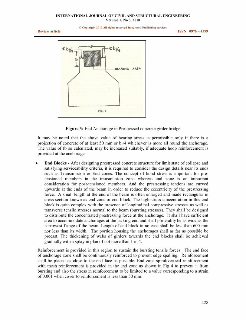
• Permissible Bearing Stress Behind Anchorage The maximum allowable stress, immediately behind the anchorages in adequately reinforced end blocks (as shown in Fig 3) may be calculated by the equation fb = 0.48 fcj √(A2/A1) or 0.8 fcj whichever is smaller;
where fb = Permissible compressive contact stress in concrete including any prevailing
stress as in the case of intermediate anchorages.
A1 = Bearing area of the anchorage concerned in shape to a square of equivalent area A2 = Maximum area of the square that can be contained within the member without overlapping the corresponding area of adjacent anchorages and concentric with the bearing area A1
fcj = Concrete strength at that time subject to a max value of fck.
INTERNATIONAL JOURNAL OF CIVIL AND STRUCTURAL ENGINEERING Volume 1, No 3, 2010
© Copyright 2010 All rights reserved Integrated Publishing services Review article ISSN 0976 – 4399
428
Figure 3: End Anchorage in Prestressed concrete girder bridge
It may be noted that the above value of bearing stress is permissible only if there is a projection of concrete of at least 50 mm or b1/4 whichever is more all round the anchorage. The value of fb so calculated, may be increased suitably, if adequate hoop reinforcement is provided at the anchorage.
• End Blocks After designing prestressed concrete structure for limit state of collapse and satisfying serviceability criteria, it is required to consider the design details near its ends such as Transmission & End zones. The concept of bond stress is important for pre tensioned members in the transmission zone whereas end zone is an important consideration for posttensioned members. And the prestressing tendons are curved upwards at the ends of the beam in order to reduce the eccentricity of the prestressing force. A small length at the end of the beam is often enlarged and made rectangular in crosssection known as end zone or end block. The high stress concentration in this end block is quite complex with the presence of longitudinal compressive stresses as well as transverse tensile stresses normal to the beam (bursting stresses). They shall be designed to distribute the concentrated prestressing force at the anchorage. It shall have sufficient area to accommodate anchorages at the jacking end and shall preferably be as wide as the narrowest flange of the beam. Length of end block in no case shall be less than 600 mm nor less than its width. The portion housing the anchorages shall as far as possible be precast. The thickening of webs of girders towards the end blocks shall be achieved gradually with a splay in plan of not more than 1 in 4.
Reinforcement is provided in this region to sustain the bursting tensile forces. The end face of anchorage zone shall be continuously reinforced to prevent edge spalling. Reinforcement shall be placed as close to the end face as possible. End zone spiral/vertical reinforcement with mesh reinforcement is provided in the end zone as shown in Fig 4 to prevent it from bursting and also the stress in reinforcement to be limited to a value corresponding to a strain of 0.001 when cover to reinforcement is less than 50 mm.

INTERNATIONAL JOURNAL OF CIVIL AND STRUCTURAL ENGINEERING Volume 1, No 3, 2010
© Copyright 2010 All rights reserved Integrated Publishing services Review article ISSN 0976 – 4399
429
Figure 4:Mesh reinforcement in End Anchorages
Figure 5: General Arrangement Diagram (GAD) of Tidding Bridge
3. Design Economics
• Sectional Dimensions For prestressed concrete structure to be most economical, the prestressing force should be minimum and eccentricity should be maximum so as to counter the moments from the load causing flexural stresses. Further the shape of the crosssection should be such that the distance between the kern points is maximum so that it can resist maximum moment. Flanged sections have larger kern distance and are therefore economical to use. For greater dead loads as compared to live load, Tsection or unsymmetrical Isection with heavier top flange is desirable. In the case of smaller dead load moments, unsymmetrical Isection with heavier bottom flange is desirable. For prestressed concrete flange beams span/depth (L/D) ratio may range from 16 to 24. The width of flange may be kept between 0.5 to 0.8 D, whereas thickness can be taken as 0.2 to 0.3 D. The web should be as thin as possible for greater efficiency but minimum thickness is necessary for proper concreting and

INTERNATIONAL JOURNAL OF CIVIL AND STRUCTURAL ENGINEERING Volume 1, No 3, 2010
© Copyright 2010 All rights reserved Integrated Publishing services Review article ISSN 0976 – 4399
430
placing of PC strands. The web thickness may be taken as 0.2 to 0.3 times the flange width subject to minimum thickness of 50 to 125 mm depending on the span length.
Box type section is economical for spans larger than 45 m and at sites with restricted depths/deck levels for safe passage of flood discharge since L/D ratio can be as high as 25 to 30. The main advantage of box section is that it facilitates placement of cables with maximum eccentricity, offers resolute section for sagging as well as hogging moments and is rigid for efficient transverse load distribution and torsion. For continuous decks, box section is very good from elastic as well as safety point of view. General Arrangement Diagram (GAD) and cross section of box girder employed at Tidding bridge in far flung Arunachal Pradesh are shown in Fig 5 & 6 respectively.
Figure 6: Cross Section of Box Girder at Tidding Bridge
In almost all the prestressed concrete constructed by BRO, single cell Box Section (trapezoidal or rectangular in shape) has been adopted. The various design considerations of box girder as stipulated in IRC : 18 –1985 are reproduced as under :
• The thickness of bottom flange of box girder should not be less than 1/30 th of the clear web spacing at the junction with bottom flange or 150 mm which ever is more.
• The minimum thickness of top flange (deck slab) shall be 150 mm for normal exposure conditions and 180 mm for severe exposure. Beyond the outer webs, thickness may be gradually reduced to have a minimum thickness of 150 mm at the tip of the cantilever.
• For top & bottom flange having prestressing cables, the thickness of such flange shall not be less than 150 mm plus diameter of duct hole.
• The thickness of diaphragms shall not be less than the minimum web thickness. The thickness of the web shall not be less than d/36 + twice the clear cover to the reinforcement + diameter of the duct hole, where d = overall depth of the beam measured from the top of the deckslab to the bottom of the beam (or) 150 mm + dia of duct holes whichever is greater.
• In box girders, effective and adequate bond & shear resistance shall be provided at the

INTERNATIONAL JOURNAL OF CIVIL AND STRUCTURAL ENGINEERING Volume 1, No 3, 2010
© Copyright 2010 All rights reserved Integrated Publishing services Review article ISSN 0976 – 4399
431
junction of the web and the slabs. The slabs may be considered as an integral part of the girder and the entire width may be assumed to be effective in compression. Haunches of minimum size of 300 mm (horizontal) and 150 mm (vertical) shall be provided at the four extreme inner corners of the box sections.
• Beam/Box section to be designed for flexure & shear and checked for torsion. Adequate control of any torsional cracking being provided by the required nominal shear reinforcement as given at Table 1.
Table 1: Requirement of nominal shear reinforcement in Box Girders for Bridges
S/No Section Minimum Reinforcement (as % of Gross c/s area)
Remarks
1. Web (vertical direction) 0.18 2. Web (Longitudinal reinf) 0.15 3. Deck slab (Top slab) 0.18 (Both ways) 4. Deck slab (Bottom slab) 0.18 (Longitudinal)
0.30 (Transverse)
HYSD bars
Figure 7: Cross section of PSC Girder bridge at Marua Bridge on Dirak Chowkham road
• Spanning Arrangement For river crossings the span lengths may be dictated by foundation requirements, height of piers, waterway area & other hydraulic considerations, navigation requirements, type of debris expected during flood stages, facility of construction and economy. Long spans with few supports make most graceful composition, constitute the least obstruction and aesthetically create sensations that are very satisfying. For spans ranging from 30 m to 35 m, prestressed concrete girder bridge with RCC slab would be economical. The same was adopted for 35 m span Marua bridge on road Dirak – Chowkham as shown at Fig 7, where three 3.15 m deep girders were placed at 2.5 m c/c. Shear connectors were used to achieve composite action between the main girder (either precast or earlier castinsitu)

INTERNATIONAL JOURNAL OF CIVIL AND STRUCTURAL ENGINEERING Volume 1, No 3, 2010
© Copyright 2010 All rights reserved Integrated Publishing services Review article ISSN 0976 – 4399
432
and infilling concrete of top slab and cross girders) as shown at Figure 8.
Figure 8: Details of Shear Connectors between main girders and top slab at Marua Bridge
Irrespective of sectional dimensions, unit cost (per metre length) of a bridge increases with span length but at the same time reduces the requirements of piers thus overall cost may remain more or less same. In any case longer spans would be economical where piers are tall and foundations deep enough. The salient features of few important multispan bridges constructed by BRO in this region are given at Table 2.
Table 2: Salient Features of few important bridges constructed by BRO
Feature Lohit Passighat Noadhing Siku Total length (m) 410 703.50 635 480 Largest Span (m) 112 117 45 60 Well foundation Twin wells Single Single Single Outer Dia of Well (m) 10.50 11.70 8.75 10.50 Steining thickness (m) 1.65 2.50 1.25 2.00 Height of Piers (m) 25 20 10 8 Superstructure Continuous Cantilever
with hinge Simply
Supported Simply
Supported Box girder depth (m) 6.35/2.75 6.5/2.5 3 3 Completion time (Years) 16 20 6 6 Cost/m (Rs. in Lacs) 4.65 3.80 4.12 3.82
• Constructional Aspects For prestressed concrete girder bridge at Marua (cross sectional details shown at Fig 9), the construction sequence adopted is given at Table 3.
Practical considerations regarding access for form work eliminate box sections of less than 1.2 m depth. Simply supported spanning arrangement was adopted at Noadhing & Siku bridges with conventional staging/shuttering system whereas for Passighat bridge (Balanced Cantilever with central hinges as shown at Fig 10) and Lohit (Continuous Superstructure with continuity/riding slab as shown at Fig 11), segmental deck/cantilever construction was used with the help of CLC Gantry eliminating the requirement of steel pipe staging system.

INTERNATIONAL JOURNAL OF CIVIL AND STRUCTURAL ENGINEERING Volume 1, No 3, 2010
© Copyright 2010 All rights reserved Integrated Publishing services Review article ISSN 0976 – 4399
433
Table 3: Construction Sequence adopted at Marua Bridge
Day Activity ‘0’ ( Zero) Casting of main Girders
14 (or on attaining 35 MPa strength whichever is earlier)
Stressing of 1 st stage cables (cable No. 1, 2, 3, 5 & 8).
21 Casting of Deck Slab & Cross Girders 56 (or 35 days after casting of deck slab
whichever is later) Stressing of 2 nd stage cables (cable No. 6 and 7)
After 56 Installation of expansion joint & casting/laying of foot path (where applicable), kerb, wearing coat & railing.
Figure 9: Cross sectional details of PSC girder at Marua Bridge
Figure 10: Balanced Cantilever spans with central hinges at Passighat Bridge

INTERNATIONAL JOURNAL OF CIVIL AND STRUCTURAL ENGINEERING Volume 1, No 3, 2010
© Copyright 2010 All rights reserved Integrated Publishing services Review article ISSN 0976 – 4399
434
Figure 11: Continuous superstructure at Lohit bridge in Arunachal Pradesh
The relative merits & demerits of continuous type superstructures are tabulated at Table 4.
Table 4: Relative Merits & Demerits of Continuous type superstructures
Advantages Disadvantages • Longer spans are possible because of
lesser span moments • Require much smaller ratio of the
deck depth at the centre of span to the span length.
• Require fewer Piers, bearings and expansion joints.
• Smaller deflections and vibrations. • Better riding quality, particularly
because of lesser joints.
• Sensitivity to the secondary stresses (settlement of supports, differential temperature, shrinkage & creep effects).
• Continuous bridges require much greater skill in construction.
• Prestressed concrete beams must be designed with concordant cables.
Balanced cantilever with central hinges is being adopted at Passighat bridge and is found advantageous visàvis simply supported decks and compare well with fully continuous decks. Hinges are positioned in the vicinity of low and zero bending moment (point of contra flexure) under dead load. By convenient location of hinges, the distribution of dead load bending moments can be made almost identical to that in continuous decks of the same shape and similar loading. However the variation of live load bending moments in cantilever decks is not as favourable as in continuous decks in which even spans away from the live load contribute in carrying this load. In the case of longer spans, however it is not the variation,

INTERNATIONAL JOURNAL OF CIVIL AND STRUCTURAL ENGINEERING Volume 1, No 3, 2010
© Copyright 2010 All rights reserved Integrated Publishing services Review article ISSN 0976 – 4399
435
but maximum value of moments which matters. For long balanced cantilever spans the general arrangement is almost the same as for fully continuous decks, and hence so also the quantities of materials. Thus is so because in long spans, dead load effect is more than live load effect. The advantages of cantilever structures are : • Unaffected by differential settlement of supports, by hogging or sagging due to
temperature differential between extreme fibers and by shrinkage or creep of deck concrete.
• No development of parasitic prestress reactions. • Conveniently allow segmental construction in certain zones which can require less form
work and scale folding and thus equally economical as continuous bridges.
However the following disadvantages sometimes outweigh the above advantages and forces the designers in abandoning cantilever schemes in favour of continuous spans.
• Poor riding quality due to more expansion joints at hinge locations. • Variation is bending moments is less favourable than in continuous spans. • Requires more number of bearings, anchorages and expansion joints. • Shear stresses can be very high at hinges which are very congested with steel and
anchorages. • Joints are generally not pleasing to eye.
4. Segmental Deck Construction
At deep gorges where erection of conventional staging/scaffolding system is not feasible and for long spans avoiding tall piers and uncertain foundations in the middle river course, cantilever construction can be conveniently employed. Cantilever construction is a method of progressive construction of a cantilever in segments and stitching them to the segments already completed by prestressing. In the insitu construction technique being followed at Lohit as well as Passighat, Pier head unit (portion of deck immediately above Pier) is first of all constructed for erecting a pair of gantry system (CLC Gantry) on the top of pier head. The gantries project beyond the pier head to support the hanging shuttering required for casting the next segment of about 2.5 m to 3 m on either side of the pier as shown at Fig 12.
Figure 12: Segmental Deck Construction
The traveling gantry (Form Traveller used at Lohit bridge) system is counterweighted for supporting the shuttering system when it is moving from completed section to forward section. In addition to this, the reaction required to take up the weight and constructional loads of the unit to be cast by the cantilever shuttering is realised by means of suspenders passed through the decking and bottom slab and anchored at the base of the previous unit.

INTERNATIONAL JOURNAL OF CIVIL AND STRUCTURAL ENGINEERING Volume 1, No 3, 2010
© Copyright 2010 All rights reserved Integrated Publishing services Review article ISSN 0976 – 4399
436
The gantry systems proceed in a systematic manner from section to section on either side of the pier after prestressing of the segment last cast. The gantry system also supports suspended scaffolding for constructional convenience and labour safety. For cantilever construction of superstructure, Box section is the most ideal deck section from the structural analysis/design point of view (flow of stresses) as well as constructional considerations. Depending on the crosssection and the extent of cantilevering portion, the entire box section is found effective in resisting the loads. The end cross girders at supports are of full depth, whereas cross girders at intermediate locations whose spacing not to exceed 45 to 55 mm need not be of full depth. At Lohit bridge the box section provided is 6.35 m deep at support locations and gradually tapered to 2.75 m at mid span location. For most of the departmentally constructed bridges, prismatic section of 3 m depth was adopted and 4.4 m deep box section for central span (65 m) of Tidding bridge is an exception.
• Soffit Surfacing Soffit surface is generally a series of “straights” segment to segment while the soffit points at segment ends may lie along a parabola if desired. Instead of threadingin/encasing of the longer prestressing cables right from the first segment onwards and keeping them dangling, it is enough to provide a cable duct alone (sometimes filled with sand) for these cables all the way until their profile commences bending. It is only then that these cables need to be threaded in (as subsequent cable threading may be difficult through a bent profile). However the maximum dangling projection of a cable at any time may be limited to about 10 to 15 m ahead of the preceding segment.
Air vents should be provided in the cable ducts over the pier and at points of change of curvature and at intervals of about 30 m as shown at Fig 13. Neat cement grout (sometimes mixed with very fine sand and aluminum powder to give body and expansion to the grout) with about 0.5 w/c ratio should be injected simultaneously from both ends of the cable, against gravity under about 7 Kg/cm 2 pressure. The vents should be plugged when full grout issues through them. Care should be taken to see that grout from either side reaches the central vent by alternate pumping.
Figure 13: Air vents in prestressing cable ducts
• Deflection & Pre Camber Generally the order of deflection of a well designed long span prestressed cantilever is about 1 in 600, which is very low. To counter the long term creep ‘dipping’ effect of deflection under all dead loads and final prestress, it is necessary to calculate the deflection at various section under this loading (based on the reduced modulus of elasticity of concrete due to creep) and give equal and opposite

INTERNATIONAL JOURNAL OF CIVIL AND STRUCTURAL ENGINEERING Volume 1, No 3, 2010
© Copyright 2010 All rights reserved Integrated Publishing services Review article ISSN 0976 – 4399
437
cambers at the soffit of these sections at the very time of construction. With this it is hoped that the structure will within about 3 years (by when majority of losses due to creep would have occurred) finally take the intended profile, thus countering the dipping effect. These pre cambers to be given during construction should be specified at the soffit level at each section. These cambers may be laid out over the decking with theodolite located over the piers always at the same time immediately after the day break, if only to somewhat offset the effect of temperature difference through the decking.
• Cables & their Profiling Generally 12 T 13 or 19 T 13 cables are used for prestressing and at least one cable pier web (preferably two) are required to stitch a segment. Generally cables to be anchored at the end of a particular segment should be anchored at about ¾ th depth of the segment below its top. Behind their anchorages these cables should raise ‘straight inclined’ through two or three segments. Placement of cables or ducts and the order of stressing and grouting shall be so arranged that the prestressing steel, when tensioned and grouted, does not adversely affect the adjoining ducts.
5. Cable Stayed/Suspension Bridges
Cable stayed bridge as shown at Fig 14 or Suspension bridge as depicted at Fig 15 are best suited for spans longer than 150 m. The inordinate delay in completion of both Passighat & Lohit bridges can be solely attributed to difficulties encountered in well sinking of pier wells located in the midstream.
Figure 14: Cable Stayed Bridge
As a result both these bridges are still under construction as against their planned completion by 1992 causing severe embarrassment at higherups as Army HQs, state Govts etc. Initially feasibility for construction a 600 m long cable stayed bridge with 360 m main span and 4 x 60 m viaduct spans on Mebo side at Passighat was carried out along with balanced cantilever bridge now being constructed. The cable stayed bridge was ruled out at that stage considering the high level technology and expertise required for construction, remoteness and inaccessibility of the area. It is now being discussed at various forums/high level meetings on

INTERNATIONAL JOURNAL OF CIVIL AND STRUCTURAL ENGINEERING Volume 1, No 3, 2010
© Copyright 2010 All rights reserved Integrated Publishing services Review article ISSN 0976 – 4399
438
the possibility for reversion to cable stayed bridge in order to expedite the construction by avoiding the ongoing well sinking at P3 & P4 pier locations. Unfortunately the solution is not so simple due contractual complications & design considerations in modifying the partly completed superstructure at Pier wells P1 & P6.
Figure 15: Cable Suspension Bridge
In the span ranges of 300 to 500 m (457 m cable stayed bridge at Hoogly), the cable stayed bridge offers far more beautiful and economical substitute for the traditional truss bridge. Comparisons have often been made between the suspension bridge and the cable stayed bridge for such large spans with the result that the cable stayed bridge is much superior to the suspension bridge as far as deformations and dynamic behaviour are concerned and also considerably cheaper.
Though the cable stayed bridge needs more steel for the deck structure and about 25% more concrete for the higher towers, it does not need very expensive anchorage blocks for anchoring the enormous cable forces of such a suspension bridge which are decisive for the cost difference thus overall cheaper & commercial than suspension bridge.
6. Conclusion
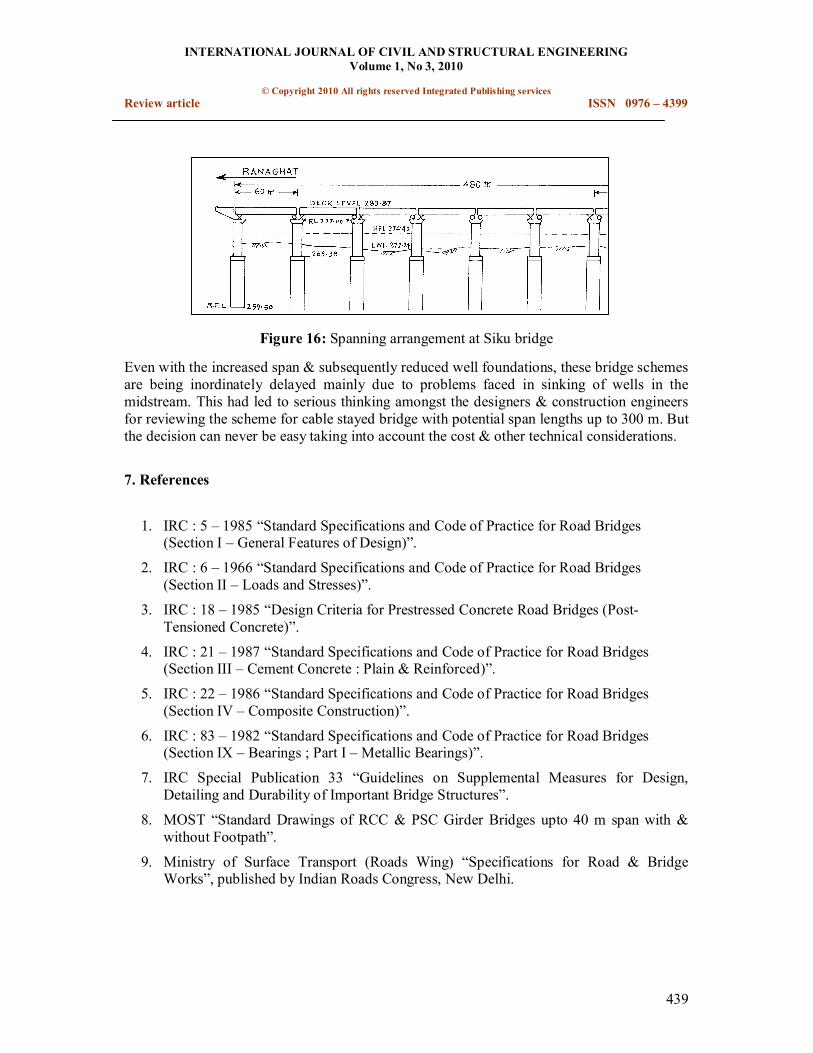
The structural scheme of the bridge as regards to spanning arrangement forms the basic & most important aspect to start with in any design of major bridge project. Simply supported spanning arrangement though simple as the name suggests is limited by span length. In order to have increased span lengths with a sole motto of reducing the number of foundations, continuous spans or balanced cantilever arrangements have been tried at Lohit & Passighat with span length up to 117 m as against mere 60 m in simply supported arrangement adopted at Siku bridge as shown in Fig 16.
INTERNATIONAL JOURNAL OF CIVIL AND STRUCTURAL ENGINEERING Volume 1, No 3, 2010
© Copyright 2010 All rights reserved Integrated Publishing services Review article ISSN 0976 – 4399
439
Figure 16: Spanning arrangement at Siku bridge
Even with the increased span & subsequently reduced well foundations, these bridge schemes are being inordinately delayed mainly due to problems faced in sinking of wells in the midstream. This had led to serious thinking amongst the designers & construction engineers for reviewing the scheme for cable stayed bridge with potential span lengths up to 300 m. But the decision can never be easy taking into account the cost & other technical considerations.
7. References
1. IRC : 5 – 1985 “Standard Specifications and Code of Practice for Road Bridges (Section I – General Features of Design)”.
2. IRC : 6 – 1966 “Standard Specifications and Code of Practice for Road Bridges (Section II – Loads and Stresses)”.
3. IRC : 18 – 1985 “Design Criteria for Prestressed Concrete Road Bridges (Post Tensioned Concrete)”.
4. IRC : 21 – 1987 “Standard Specifications and Code of Practice for Road Bridges (Section III – Cement Concrete : Plain & Reinforced)”.
5. IRC : 22 – 1986 “Standard Specifications and Code of Practice for Road Bridges (Section IV – Composite Construction)”.
6. IRC : 83 – 1982 “Standard Specifications and Code of Practice for Road Bridges (Section IX – Bearings ; Part I – Metallic Bearings)”.
7. IRC Special Publication 33 “Guidelines on Supplemental Measures for Design, Detailing and Durability of Important Bridge Structures”.
8. MOST “Standard Drawings of RCC & PSC Girder Bridges upto 40 m span with & without Footpath”.
9. Ministry of Surface Transport (Roads Wing) “Specifications for Road & Bridge Works”, published by Indian Roads Congress, New Delhi.