economizers - allied commercial7.5-12.5... · 3 figure 5 - wiring detail install mixed air sensor...
TRANSCRIPT
1
WARNINGImproper installation, adjustment, alteration, service or maintenance can cause property damage, personal injury or loss of life. Installation and service must be performed by a qualified installer, service agency or the gas supplier
CAUTIONDanger of sharp metallic edges. Can cause injury.Take care when servicing unit to avoid accidental contact with sharp edges.
INSTALLATION INSTRUCTIONS FOR ECONOMIZERS USED WITH ZC,ZG,ZH 092-150 UNITS
Z1ECON30B-1 ECONOMIZER(Cat No. 10Z29)
ECONOMIZERS
!
!
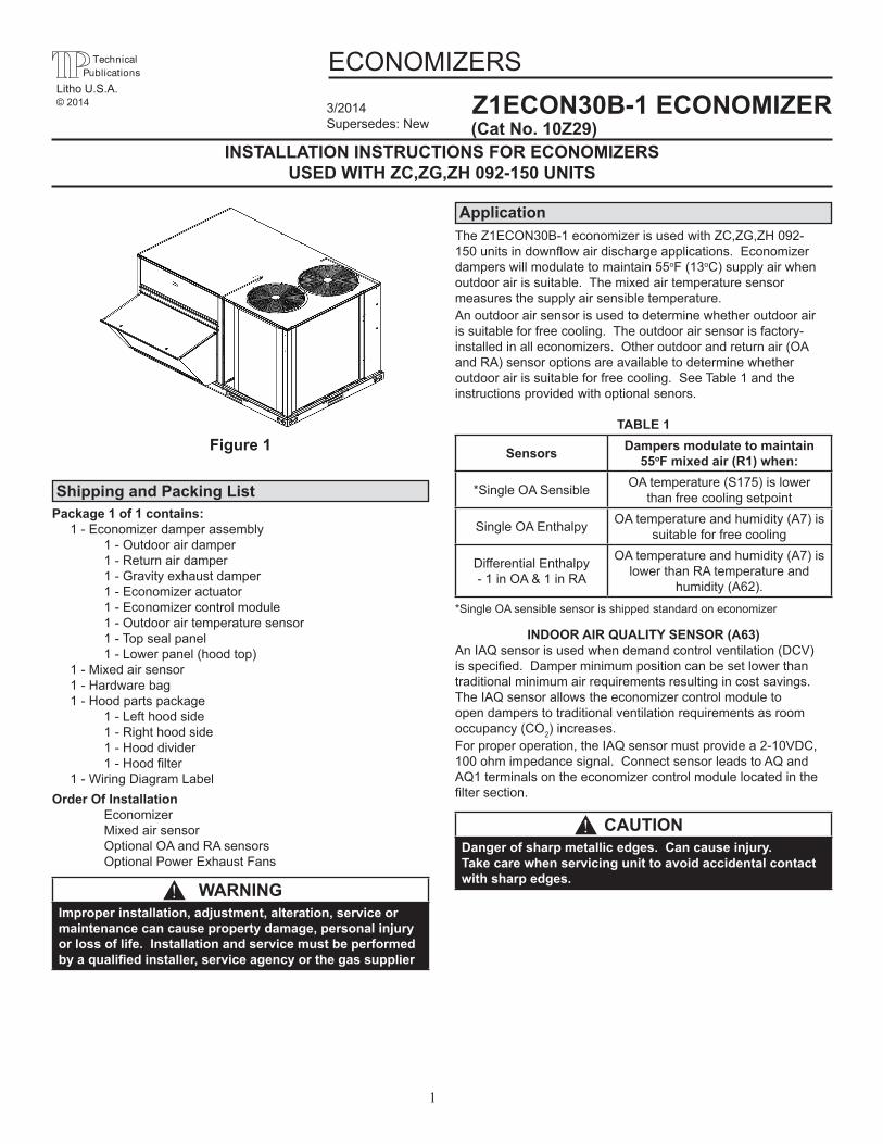
Package 1 of 1 contains: 1 - Economizer damper assembly 1 - Outdoor air damper 1 - Return air damper 1 - Gravity exhaust damper 1 - Economizer actuator 1 - Economizer control module 1 - Outdoor air temperature sensor 1 - Top seal panel 1 - Lower panel (hood top) 1 - Mixed air sensor 1 - Hardware bag 1 - Hood parts package 1 - Left hood side 1 - Right hood side 1 - Hood divider 1-Hoodfilter 1 - Wiring Diagram LabelOrder Of Installation Economizer Mixed air sensor Optional OA and RA sensors Optional Power Exhaust Fans
Shipping and Packing List
ApplicationThe Z1ECON30B-1 economizer is used with ZC,ZG,ZH 092-150unitsindownflowairdischargeapplications.Economizerdampers will modulate to maintain 55oF (13oC) supply air when outdoorairissuitable.Themixedairtemperaturesensormeasuresthesupplyairsensibletemperature.An outdoor air sensor is used to determine whether outdoor air issuitableforfreecooling.Theoutdoorairsensorisfactory-installedinalleconomizers.Otheroutdoorandreturnair(OAand RA) sensor options are available to determine whether outdoorairissuitableforfreecooling.SeeTable1andtheinstructionsprovidedwithoptionalsenors.
INDOOR AIR QUALITY SENSOR (A63)An IAQ sensor is used when demand control ventilation (DCV) isspecified.Damperminimumpositioncanbesetlowerthantraditionalminimumairrequirementsresultingincostsavings.The IAQ sensor allows the economizer control module to open dampers to traditional ventilation requirements as room occupancy (CO2)increases.For proper operation, the IAQ sensor must provide a 2-10VDC, 100ohmimpedancesignal.ConnectsensorleadstoAQandAQ1 terminals on the economizer control module located in the filtersection.
TABLE 1
Sensors Dampers modulate to maintain55oF mixed air (R1) when:
*Single OA Sensible OA temperature (S175) is lowerthan free cooling setpoint
Single OA Enthalpy OA temperature and humidity (A7) is suitable for free cooling
Differential Enthalpy- 1 in OA & 1 in RA
OA temperature and humidity (A7) is lower than RA temperature and
humidity(A62).
Figure 1
*Single OA sensible sensor is shipped standard on economizer
Litho U.S.A.© 2014 3/2014
Supersedes: New

2
Figure 2
Install Economizer1. Disconnect all power sources to the unit2. Remove the following panels from the unit; - Filter door panel - Return chamber panel - Blower access panel - Control panelWhenfilterdoorandreturnchamberareremovedtherewill be a cross support still in the unit streatching from side to side of the return chamber
3. Removehoodpartspackage.4. Installdamperassemblyintounitunderthecrosssupport.
Fit opening in bottom of damper assembly over the return air opening.SeeFigure3.
5. The upper panel of the economizer will screw into the cross supportthroughpre-punchedholes.
6. Securetheeconomizertounitbasepanwithfivescrews.
Blower access panel (backside)Filter door
Return chamber panel
Figure 4
Filter doorTop seal panel
Outside air temperature sensor
Outsideair damper
Plug for optional power
exhaust
See note 5above
Grommet for high voltagepower exhaust wires 9 pin economizer/
mixed air sensorplug (J142)
Gravityexhaust damper
Figure 3 - Economizer Installtion
EconomizerJ10, P10 Plug
3
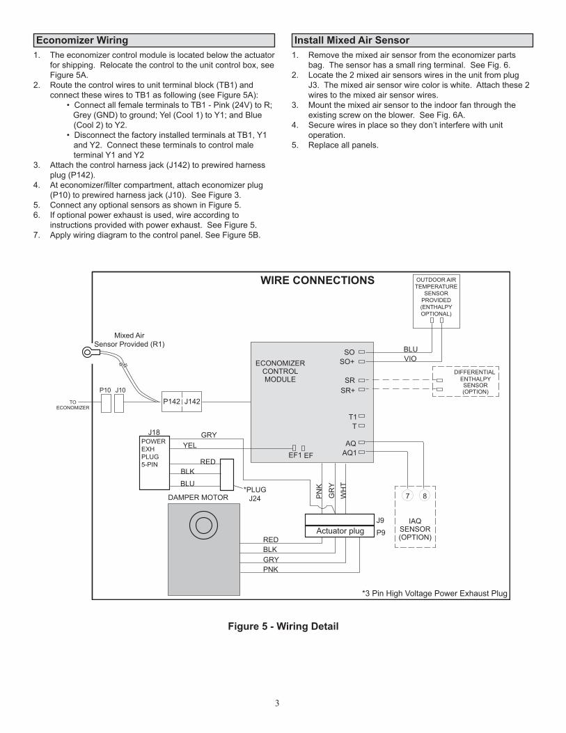
Figure 5 - Wiring Detail
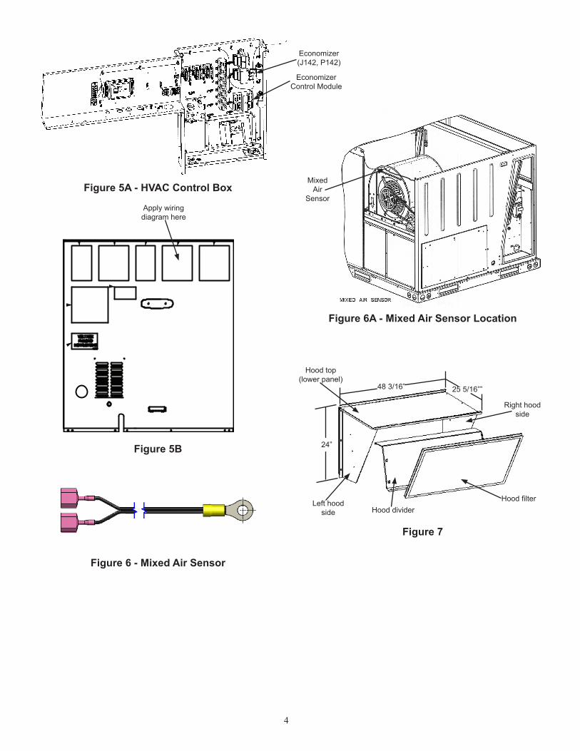
Install Mixed Air Sensor 1. Remove the mixed air sensor from the economizer parts
bag.Thesensorhasasmallringterminal.SeeFig.6.2. Locate the 2 mixed air sensors wires in the unit from plug
J3.Themixedairsensorwirecoloriswhite.Attachthese2wirestothemixedairsensorwires.
3. Mount the mixed air sensor to the indoor fan through the existingscrewontheblower.SeeFig.6A.
4. Secure wires in place so they don’t interfere with unit operation.
5. Replaceallpanels.
Economizer Wiring1. Theeconomizercontrolmoduleislocatedbelowtheactuator
forshipping.Relocatethecontroltotheunitcontrolbox,seeFigure5A.
2. Routethecontrolwirestounitterminalblock(TB1)andconnect these wires to TB1 as following (see Figure 5A):
• Connect all female terminals to TB1 - Pink (24V) to R; Grey (GND) to ground; Yel (Cool 1) to Y1; and Blue (Cool2)toY2. • Disconnect the factory installed terminals at TB1, Y1 andY2.Connecttheseterminalstocontrolmale terminal Y1 and Y23. Attachthecontrolharnessjack(J142)toprewiredharness
plug(P142).4. Ateconomizer/filtercompartment,attacheconomizerplug
(P10)toprewiredharnessjack(J10).SeeFigure3.5. ConnectanyoptionalsensorsasshowninFigure5.6. Ifoptionalpowerexhaustisused,wireaccordingto
instructionsprovidedwithpowerexhaust.SeeFigure5.7. Applywiringdiagramtothecontrolpanel.SeeFigure5B.
P142TO
P10 J10
J142
ECONOMIZERCONTROLMODULE
RED
RED
GRYYEL
J18
PN
K
GR
YW
HT
BLK
BLK
BLUVIO
GRY
*PLUGJ24
PNK
DAMPER MOTOR
BLU
8
IAQSENSOR(OPTION)
7
J9
P9
DIFFERENTIAL ENTHALPYSENSOR(OPTION)
SRSR+
SO+SO
TT1
EF1 EF AQ1AQ
Actuator plug
*3 Pin High Voltage Power Exhaust Plug
POWER EXHPLUG5-PIN
OUTDOOR AIRTEMPERATURE
SENSORPROVIDED(ENTHALPYOPTIONAL)
ECONOMIZER
Mixed AirSensor Provided (R1)
WIRE CONNECTIONS
4
Figure 7
Right hoodside
HoodfilterHood divider
Left hoodside
Hood top(lower panel)
24”
48 3/16” 25 5/16””
Figure 6A - Mixed Air Sensor Location
Mixed Air
Sensor
Figure 6 - Mixed Air Sensor
Figure 5A - HVAC Control Box
Figure 5B
Economizer(J142, P142)
Apply wiring diagram here
EconomizerControl Module
5
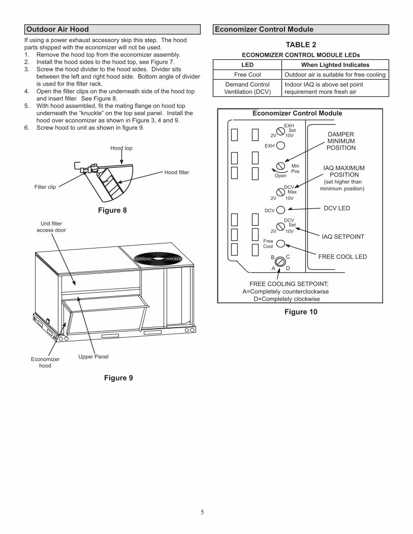
Outdoor Air Hood Economizer Control ModuleIfusingapowerexhaustaccessoryskipthisstep.Thehoodpartsshippedwiththeeconomizerwillnotbeused.1. Removethehoodtopfromtheeconomizerassembly.2. Installthehoodsidestothehoodtop,seeFigure7.3. Screwthehooddividertothehoodsides.Dividersits
betweentheleftandrighthoodside.Bottomangleofdividerisusedforthefilterrack.
Figure 8
Figure 9
Figure 10
4. Openthefilterclipsontheunderneathsideofthehoodtopandinsertfilter.SeeFigure8.
5. Withhoodassembled,fitthematingflangeonhoodtopunderneaththe“knuckle”onthetopsealpanel.InstallthehoodovereconomizerasshowninFigure3,4and9.
6. Screwhoodtounitasshowninfigure9.
TABLE 2ECONOMIZER CONTROL MODULE LEDsLED When Lighted Indicates
Free Cool Outdoor air is suitable for free coolingDemand ControlVentilation (DCV)
Indoor IAQ is above set point requirement more fresh air
A6 ENTHALPY CONTROL
A
B C
D
Open
MinPos
FREE COOLING SETPOINT;A=Completely counterclockwise
D=Completely clockwise
FREE COOL LED
FreeCool
DCV
EXH
EXHSet
2V 10V
DCVMax
2V 10V
DCVSet
2V 10VIAQ SETPOINT
DCV LED
DAMPERMINIMUMPOSITION
IAQ MAXIMUMPOSITION
(set higher thanminimum position)
Unitfilteraccess door
Upper PanelEconomizerhood
Hood top
Hoodfilter
Filter clip
Economizer Control Module
6
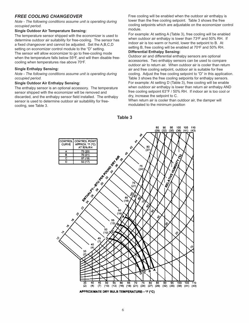
Table 3
FREE COOLING CHANGEOVERNote - The following conditions assume unit is operating during occupied period.Single Outdoor Air Temperature Sensing:The temperature sensor shipped with the economizer is used to determineoutdoorairsuitabilityforfree-cooling.Thesensorhasafixedchangeoverandcannotbeadjusted.SettheA,B,C,Dsettingoneconomizercontrolmoduletothe“D”setting.The sensor will allow economizer to go to free-cooling mode when the temperature falls below 55oF, and will then disable free-cooling when temperatures rise above 70oF.
Free cooling will be enabled when the outdoor air enthalpy is lowerthanthefreecoolingsetpoint.Table3showsthefreecoolingsetpointswhichareadjustableontheeconomizercontrolmodule.For example: At setting A (Table 3), free cooling will be enabled when outdoor air enthalpy is lower than 73oFand50%RH.Ifindoorairistoowarmorhumid,lowerthesetpointtoB.Atsetting B, free cooling will be enabled at 70oFand50%RH.Differential Enthalpy Sensing:Outdoor air and differential enthalpy sensors are optional accessories.Twoenthalpysensorscanbeusedtocompareoutdoorairtoreturnair.Whenoutdoorairiscoolerthanreturnair and free cooling setpoint, outdoor air is suitable for free cooling.Adjustthefreecoolingsetpointto“D”inthisapplication.Table3showsthefreecoolingsetpointsforenthalpysensors.For example: At setting D (Table 3), free cooling will be enable when outdoor air enthalpy is lower than return air enthalpy AND freecoolingsetpoint63°F/50%RH.Ifindoorairistoocoolordry,increasethesetpointtoC.When return air is cooler than outdoor air, the damper will modulated to the minimum position
Single Enthalpy Sensing:Note - The following conditions assume unit is operating during occupied period.Single Outdoor Air Enthalpy Sensing:Theenthalpysensorisanoptionalaccessory.Thetemperaturesensor shipped with the economizer will be removed and discarded,andtheenthalpysensorfieldinstalled.Theenthalpysensor is used to determine outdoor air suitablility for free-cooling,seeTable3.

7
DAMPER MINIMUM POSITION SETTINGNOTE - 24 volts must be provided at unit 24 volt leads R and OC to enable economizer operation (allowing minimum fresh air). Typically a separately ordered thermostat or energy management system with an occupied/unoccupied output is connected between R and OC leads. The thermostat will provide 24 volts to the economizer control during the occupied time period to enable the economizer. If a device is not used to enable the economizer, install a jumper between R and OC leads R and OC to maintain minimum position continuously.Make wire connections to leads R and OC as shown in literature provided with thermostat or energy management system.1. Setthermostattooccupiedmodeifthefeatureisavailable.
MakesurejumperisinplacebetweenleadsRandOCifusingathermostatwhichdoesnothavethefeature.
2. Rotate MIN POS SET potentiometer to approximate desired freshairpercentage.Usecarewhenadjustingminimumpotentiometertoavoiddamagingpotentiometer.
Note - Damper minimum position can be set lower than traditional minimum air requirements when an IAQ sensor is specified.
3. Measureoutdoorairtemperature.Markthepointonthebottom line of chart 1 and label the point “A” (40oF, 4oC shown).
4. Measurereturnairtemperature.Markthatpointonthetopline of chart 1 and label the point “B” (74oF, 23oCshown).
5. Measuremixedair(outdoorandreturnair)temperature.Mark that point on the top line of chart 1 and label point “C” (70oF, 21oCshown).
6. DrawastraightlinebetweenpointAandB.7. DrawaverticallinethroughpointC.8. Drawahorizontallinewherethetwolinesmeet.Readthe
percentoffreshairintakeontheside.9. Iffreshairpercentageislessthandesired,adjustMIN
POSSETpotentiometerclockwise(furtheropen).Iffreshairpercentageismorethandesired,adjustMINPOSSETpotentiometercounterclockwise(lessopen).Repeatsteps 3 through 8 until calculation reads desired fresh air percentage.
−20−29
−10−23
0−18
10−12
20−7
30−1
404
5010
6016
7021
8027
9032
10038
0
10
30
40
50
60
70
80
90
100
20
OUTDOOR AIR TEMPERATURE
0
10
30
40
50
60
70
80
90
100
20
MIXED AND RETURN AIR TEMPERATURE
CHART 1CALCULATE MINIMUM FRESH AIR PERCENTAGE
A
BC
FC
FC
−20−29
−10−23
0−18
10−12
20−7
30−1
404
5010
6016
7021
8027
9032
10038
FC
FC
8
DCV SET AND DCV MAX SETTINGThe DCV SET potentiometer is factory-set at approximately 50% ofthepotentiometerrange.Usingastandard1-2000ppmCO2 sensor, dampers will start to open when the IAQ sensor reads approximately1000ppm.AdjusttheDCVSETpotentiometertotheapproximatesettingspecifiedbythecontrolscontractor.Refertofigure10.The DCV MAX potentiometer is factory-set at approximately 50%ofthepotentiometerrangeor6VDC.Damperswillopenapproximately half way when CO2risesabovesetpoint.AdjusttheDCVMAXpotentiometertotheapproximatesettingspecifiedbythecontrolcontractor.Refertofigure10.Note - DCV Max must be set higher than economizer minimum position setting for proper demand control ventilation.
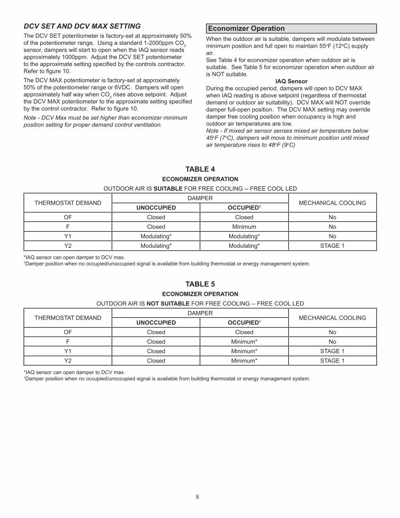
Economizer OperationWhen the outdoor air is suitable, dampers will modulate between minimum position and full open to maintain 55oF (12oC) supply air.See Table 4 for economizer operation when outdoor air is suitable.SeeTable5foreconomizeroperationwhenoutdoorairisNOTsuitable.
IAQ SensorDuring the occupied period, dampers will open to DCV MAX when IAQ reading is above setpoint (regardless of thermostat demandoroutdoorairsuitability).DCVMAXwillNOToverridedamperfull-openposition.TheDCVMAXsettingmayoverridedamper free cooling position when occupancy is high and outdoorairtemperaturesarelow.Note - If mixed air sensor senses mixed air temperature below 45oF (7oC), dampers will move to minimum position until mixed air temperature rises to 48oF (9oC)
TABLE 4ECONOMIZER OPERATION
OUTDOOR AIR IS SUITABLE FOR FREE COOLING -- FREE COOL LED
THERMOSTAT DEMANDDAMPER
MECHANICAL COOLINGUNOCCUPIED OCCUPIED1
OF Closed Closed NoF Closed Minimum No
Y1 Modulating* Modulating* NoY2 Modulating* Modulating* STAGE 1
TABLE 5ECONOMIZER OPERATION
OUTDOOR AIR IS NOT SUITABLE FOR FREE COOLING -- FREE COOL LED
THERMOSTAT DEMANDDAMPER
MECHANICAL COOLINGUNOCCUPIED OCCUPIED1
OF Closed Closed NoF Closed Minimum* No
Y1 Closed Minimum* STAGE 1Y2 Closed Minimum* STAGE 1
*IAQsensorcanopendampertoDCVmax.1Damperpositionwhennooccupied/unoccupiedsignalisavailablefrombuildingthermostatorenergymanagementsystem.
*IAQsensorcanopendampertoDCVmax.1Damperpositionwhennooccupied/unoccupiedsignalisavailablefrombuildingthermostatorenergymanagementsystem.
FormNo.1-1P